the brihan mumbai electric supply & transport undertaking · pdf filethe brihan mumbai...
TRANSCRIPT
THE BRIHAN MUMBAI ELECTRIC SUPPLY & TRANSPORT UNDERTAKING (OF THE BRIHANMUMBAI MAHANAGARPALIKA)
Specification No.1390117-H
SECTION 1: GENERAL
1.1 Tender Document : 1.1.1 This tender document shall be read and understood as a whole inclusive of all
Annexures, drawings etc. and every section or sub-section of this document shall be incorporated in proper context with other sections contained herein.
1.1.2 This specification covers the basic requirements in respect of 11kV, 250 MVA, Indoor,
VCB Switchgears integrated with associated indoor control and relay panels for installation at various Distribution Sub-stations in Mumbai.
1.1.3 All work covered by this specification shall be carried out in accordance with the
‘General Conditions of Contract’. 1.1.4 Wherever the directions to the tenderers embodied herein conflict with those specified in
the General Conditions of Contract, the former shall be binding in preference to the latter.
1.2 Legislation: 1.2.1 The whole of the equipment shall comply in every respect with the provisions of relevant
Government Legislations and/or Rules and Regulations governing manufacture, installation, operation and maintenance of the equipment.
1.2.2 Tenderers shall ensure that all safety measures are provided in the equipment against
hazards to life and property and that the proper installation and use of the equipment shall not contravene any enactments, rules and by-laws of the Government and the Local Authority.
1.3 Departure from Specification :
1.3.1 If due to any reason tenderers find it necessary to depart from the provisions of any
section of the specification such departures shall be clearly stated and underlined giving full reasons.
1.3.2 If the departures from the provisions of any section of this specification are not notified in
writing it will be presumed that tenderers will abide by this specification. 1.3.3 Any suggestion, comment or advice to include in this document additional provisions in
respect of any special device or attachment/necessary but not already specified herein, may be put forward by the tenderers giving full details of the special/additional features of the equipment together with the justification for its inclusion.
1.4 Technical Data : 1.4.1 Tenderers shall give full specifications of the equipment/materials offered and shall
supply technical literature and descriptive particulars together with drawing and illustrations to indicate the type and design of the equipment/material offered.
1.4.2 Tenderers shall supply such technical data, characteristics and statistical information as
required to study the comparative merits and performance of different types and design of the equipments/materials.
1.5 Materials and Workmanship : 1.5.1 The equipment/materials shall conform to the best engineering practice in design,
materials and construction so as to ensure reliability, economy and safe and convenient operation.
1.5.2 Tenderers shall supply all incidental items necessary or usual for such equipment for
efficient working and for erection/installation purpose. 1.5.3 Manufacturers shall give details of the experience in the supply of similar equipment. A
list of important customers who have been supplied with similar equipment with details of order executed shall be furnished. Details shall include rating of the equipment, quantity, purchase order reference etc.
1.5.4 Guarantee : 1.5.4.1 All switchgears supplied against this specification shall be guaranteed for a period of 66
months from the date of acceptance or 60 months from the date of installation, whichever is earlier for satisfactory operation of the operation of switchgear. However, any engineering error, omission, wrong provisions, etc. which do not have any effect on the time period, shall be attended / rectified by supplier as and when observed / pointed out without any price implication to the entire satisfaction of the Undertaking.
1.5.5 The successful tenderer shall make good at his own expense all necessary alterations
replacement to prevent any recurrence of such defects on all the equipment/materials supplied by him.
1.5.6 All corresponding similar materials and removable parts shall be made to guage and
shall be interchangeable with each other. 1.5.7 The equipment/materials may be rejected at discretion of the General Manager if the test
results are not satisfactory and the permissible tolerances are exceeded. 1.6 Instructions for Erection / Installation/ Periodic maintenance :
Tenderers shall furnish the necessary instruction manual for erection/installation of the equipment/materials and shall also state precautions/provisions if any to be made for proper use afterwards.
SECTION 2 : DESCRIPTION OF THE POWER SYSTEM
2.1 Grid :
2.1.1 The Tata Power Co. Ltd. (TPCL) and the Maharashtra State Electricity Generation Co.
Ltd. have their generating stations located in different parts of Maharashtra State and form an interconnected transmission system in the Mumbai-Pune Region.
2.1.2 Power from this system is transmitted at 220kV/110kV through overhead conductors and
underground cables amongst others to TPCL’s five main receiving stations at Backbay, Carnac, Parel, Dharavi and Mahalaxmi situated in the island of Mumbai, where they have installed either delta/star or star/zigzag step down transformers with star point effectively earthed for making power available to their consumers at 110/33/22kV.
2.2 Existing B.E.S.T. System : 2.2.1 The B.E.S. & T. Undertaking on behalf of Brihanmumbai Mahanagarpalika (who are the
licensee for the distribution of electric power within the City Limits of Mumbai) receives power in bulk from the Tata Power Co. Ltd. at 110/33/22kV, 3 Phase, 50 Hz.
2.2.2 Bulk power at 110/33/22kV is transmitted from TPCL’s f ive main receiving stations
through effectively earthed underground cables to B.E.S.T.’s receiving substations situated at different localities in Mumbai where the B.E.S. & T. Undertaking has installed 110/33kV, 110/11kV, 33/11kV, 22/11kV, Star-zigzag, star/star, delta/star power transformers of Vector group Ynzn11, Ynyno, 31 Dyn1 with neutral earth. Where the transformation is 110/11kV or 110/33kV, 22/11kV or 33/11kV the star point of the transformers has been effectively earthed. The power transformers are provided with OLTC gear to regulate and maintain the 11kV voltage fairly constant.
2.2.3 Underground 11kV (effectively earthed) feeder cables radiate from the B.E.S.T.
receiving substations to supply power to a large number of distribution substations and to certain consumer’s substations. These feeders form a radial network under which each feeder supplies approximately 4 to 5 substations in the series.
2.2.4 Power at 11kV is stepped down to 415/240V at the distribution substations where the various sizes of 11kV/415-240 Volt delta/star transformers of vector group 41 Dyn11 are installed. The star point of this transformer is solidly earthed and is also brought out to an insulated terminal for the 3 phase, 4 wire distribution system.
2.2.5 The 415/240V secondary distribution system comprises of a vast network of
underground four core cables, suitably sectionalized by means of distribution pillars, to which service lines are teed off to supply power to medium and low voltage consumers.
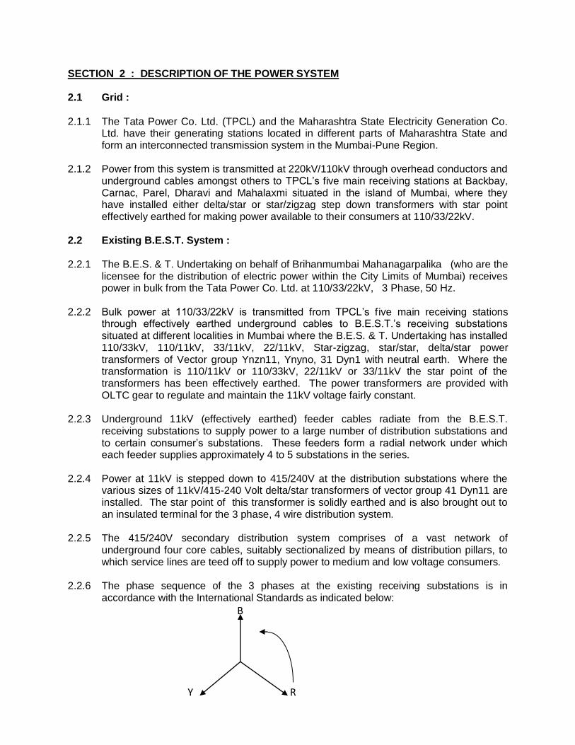
2.2.6 The phase sequence of the 3 phases at the existing receiving substations is in
accordance with the International Standards as indicated below:
B
Y R
SECTION 3 : SCOPE OF SUPPLY
3.1.1 The equipment offered shall be complete with all parts necessary for their effective and
trouble-free operation, such p a r t s will be deemed to be within the scope of the supply irrespective of whether they are specifically indicated in the commercial order or not.
3.1.2 The respective drawing along with notes and specification attached hereto form an
integral part of this specification for all purposes. 3.1.3 It is not the intent to specify herein complete details of design and construction.
The equipment offered shall conform to the relevant standards and be of high quality, sturdy, robust and of good design and workmanship complete in all respects and capable to perform continuous and satisfactory operations in the actual service conditions at site and shall have sufficiently long life in service as per statutory requirements. In actual practice, not withstanding any anomalies, discrepancies, omissions, in-completeness, etc. in these specifications and attached drawings, the design and constructional aspects, including materials and dimensions, will be subject to good engineering practice in conformity with the required quality of the product by virtue of various stipulations in that respect in the relevant Indian Standards, IEC standards, I.E. Rules, I.E. Act and other statutory provisions.
3.1.4 The Tenderer/supplier shall bind himself to abide by these considerations to the
entire satisfaction of the purchaser and wil l be required to adjust such details at no extra cost to the purchaser over and above the tendered rates and prices.
3.2.0 SERVICE CONDITIONS :
3.2.1 System particulars :
a. Nominal system voltage --- 11 kV
b. Corresponding highest system voltage --- 12 kV
c. Frequency --- 50 Hz ± 3%
d. Number of phases --- 3
e.
Neutral earthing --- Solidly
grounded
f. Short Circuit Current Rating ...
--- 13.2 kA
3.2.2 Equipment supplied against the specification shall be suitable for satisfactory operation under the following tropical conditions:-
a) Air Temperature in Shade
Highest temperature recorded : 40.6 C
Lowest temperature recorded : 11.7 C
24 Hours daily average : 26.0 C
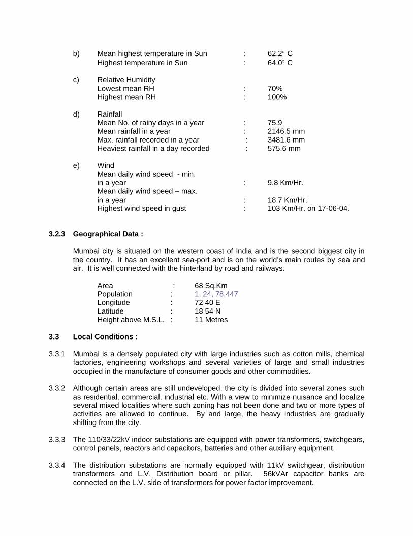
b) Mean highest temperature in Sun : 62.2 C
Highest temperature in Sun : 64.0 C c) Relative Humidity
Lowest mean RH : 70% Highest mean RH : 100%
d) Rainfall
Mean No. of rainy days in a year : 75.9 Mean rainfall in a year : 2146.5 mm Max. rainfall recorded in a year : 3481.6 mm Heaviest rainfall in a day recorded : 575.6 mm
e) Wind
Mean daily wind speed - min. in a year : 9.8 Km/Hr. Mean daily wind speed – max. in a year : 18.7 Km/Hr. Highest wind speed in gust : 103 Km/Hr. on 17-06-04.
3.2.3 Geographical Data :
Mumbai city is situated on the western coast of India and is the second biggest city in the country. It has an excellent sea-port and is on the world’s main routes by sea and air. It is well connected with the hinterland by road and railways.
Area : 68 Sq.Km Population : 1, 24, 78,447 Longitude : 72 40 E Latitude : 18 54 N Height above M.S.L. : 11 Metres 3.3 Local Conditions :
3.3.1 Mumbai is a densely populated city with large industries such as cotton mills, chemical
factories, engineering workshops and several varieties of large and small industries occupied in the manufacture of consumer goods and other commodities.
3.3.2 Although certain areas are still undeveloped, the city is divided into several zones such
as residential, commercial, industrial etc. With a view to minimize nuisance and localize several mixed localities where such zoning has not been done and two or more types of activities are allowed to continue. By and large, the heavy industries are gradually shifting from the city.
3.3.3 The 110/33/22kV indoor substations are equipped with power transformers, switchgears,
control panels, reactors and capacitors, batteries and other auxiliary equipment. 3.3.4 The distribution substations are normally equipped with 11kV switchgear, distribution
transformers and L.V. Distribution board or pillar. 56kVAr capacitor banks are connected on the L.V. side of transformers for power factor improvement.
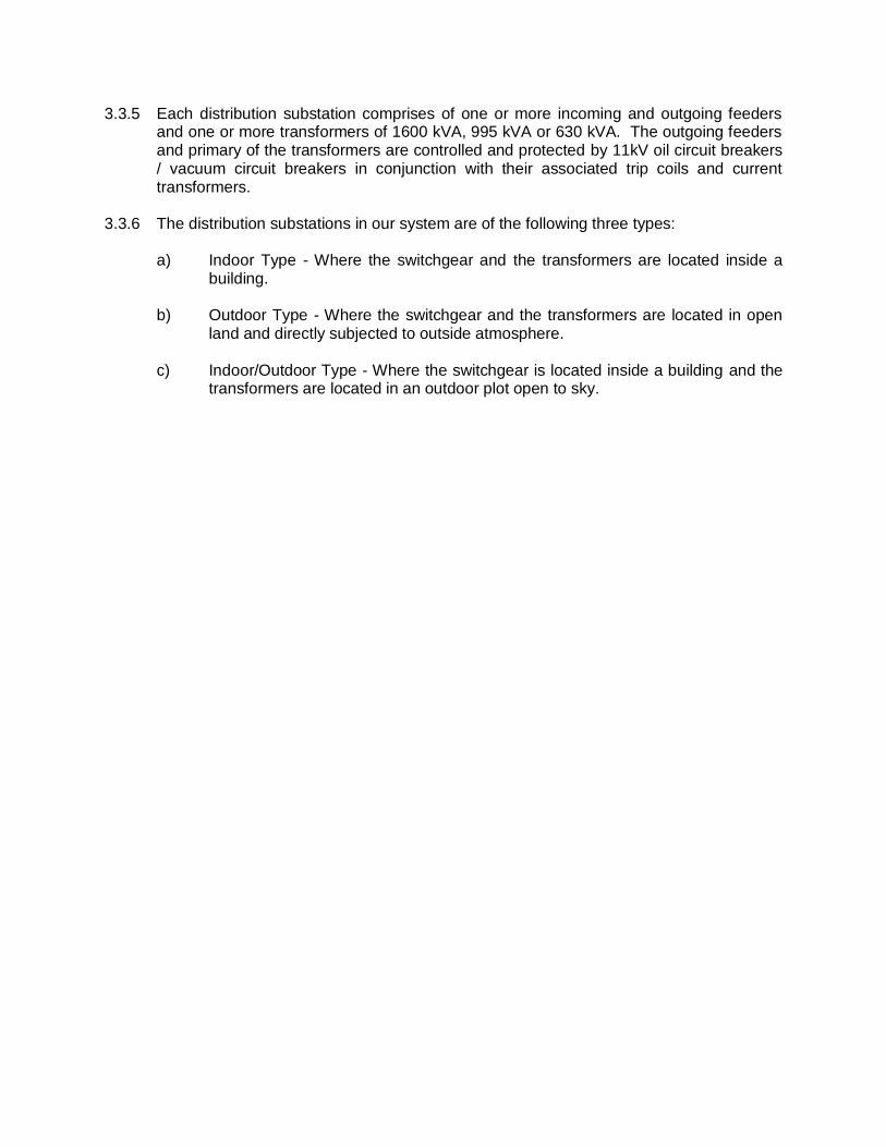
3.3.5 Each distribution substation comprises of one or more incoming and outgoing feeders and one or more transformers of 1600 kVA, 995 kVA or 630 kVA. The outgoing feeders and primary of the transformers are controlled and protected by 11kV oil circuit breakers / vacuum circuit breakers in conjunction with their associated trip coils and current transformers.
3.3.6 The distribution substations in our system are of the following three types:
a) Indoor Type - Where the switchgear and the transformers are located inside a building.
b) Outdoor Type - Where the switchgear and the transformers are located in open
land and directly subjected to outside atmosphere. c) Indoor/Outdoor Type - Where the switchgear is located inside a building and the
transformers are located in an outdoor plot open to sky.
SECTION 4 : CODES AND STANDARDS
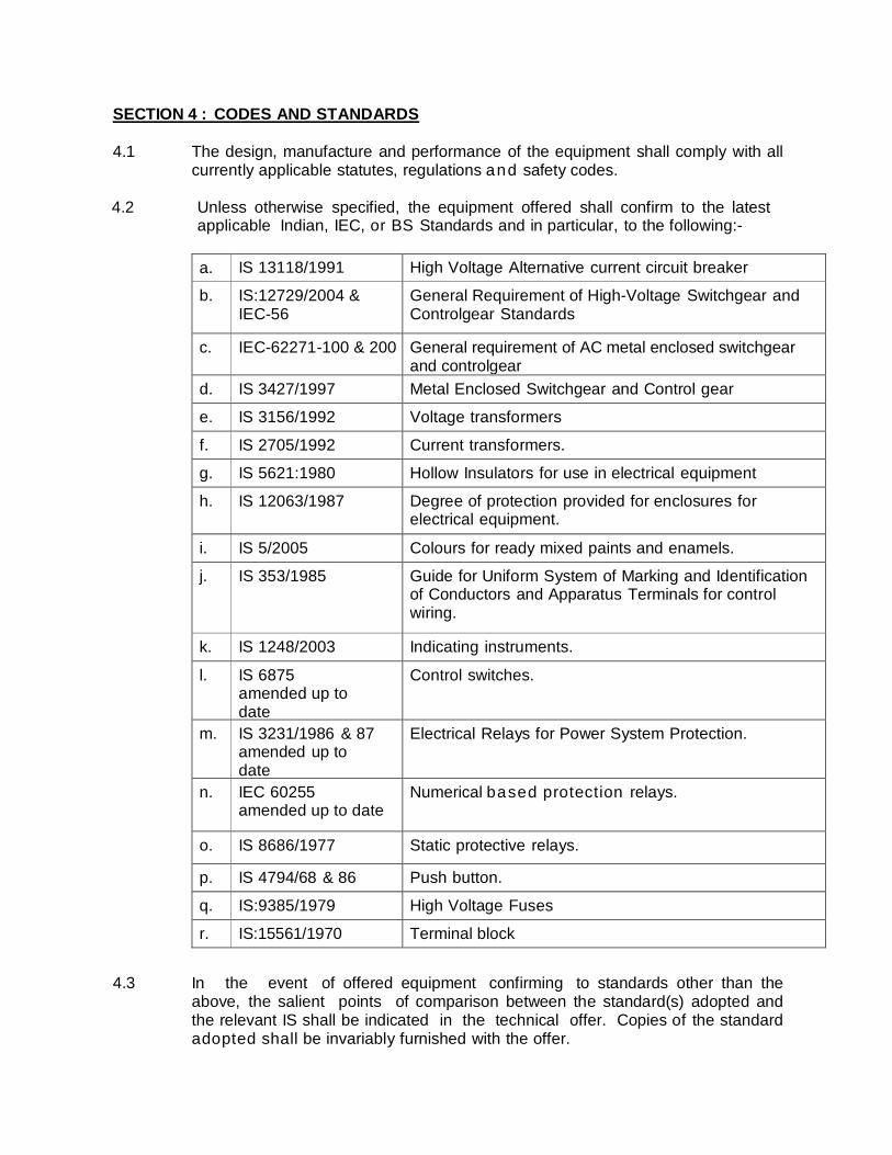
4.1 The design, manufacture and performance of the equipment shall comply with all
currently applicable statutes, regulations and safety codes. 4.2 Unless otherwise specified, the equipment offered shall confirm to the latest
applicable Indian, IEC, or BS Standards and in particular, to the following:-
a. IS 13118/1991 High Voltage Alternative current circuit breaker
b. IS:12729/2004 & IEC-56
General Requirement of High-Voltage Switchgear and Controlgear Standards
c. IEC-62271-100 & 200 General requirement of AC metal enclosed switchgear and controlgear
d. IS 3427/1997 Metal Enclosed Switchgear and Control gear
e. IS 3156/1992 Voltage transformers
f. IS 2705/1992 Current transformers.
g. IS 5621:1980 Hollow Insulators for use in electrical equipment
h. IS 12063/1987 Degree of protection provided for enclosures for electrical equipment.
i. IS 5/2005 Colours for ready mixed paints and enamels.
j. IS 353/1985 Guide for Uniform System of Marking and Identification of Conductors and Apparatus Terminals for control wiring.
k. IS 1248/2003 Indicating instruments.
l. IS 6875 amended up to date
Control switches.
m. IS 3231/1986 & 87 amended up to date
Electrical Relays for Power System Protection.
n. IEC 60255 amended up to date
Numerical based protection relays.
o. IS 8686/1977 Static protective relays.
p. IS 4794/68 & 86 Push button.
q. IS:9385/1979 High Voltage Fuses
r. IS:15561/1970 Terminal block
4.3 In the event of offered equipment confirming to standards other than the above, the salient points of comparison between the standard(s) adopted and the relevant IS shall be indicated in the technical offer. Copies of the standard adopted shall be invariably furnished with the offer.
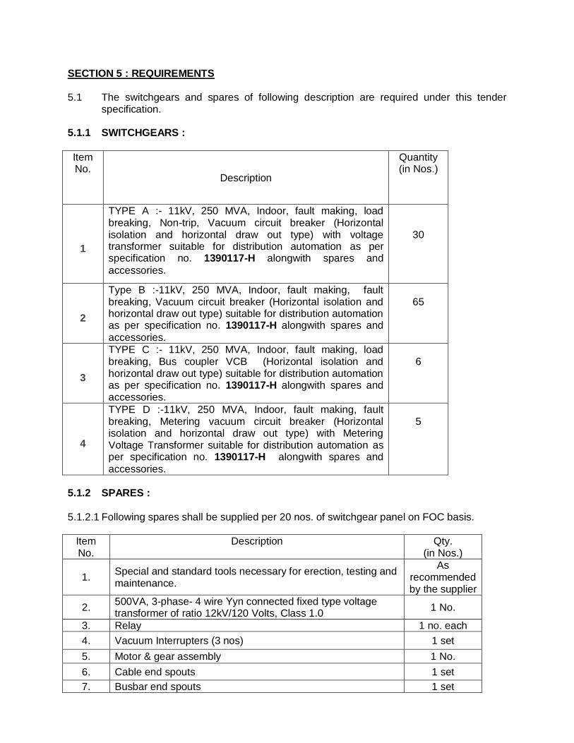
SECTION 5 : REQUIREMENTS 5.1 The switchgears and spares of following description are required under this tender
specification. 5.1.1 SWITCHGEARS :
Item No.
Description
Quantity (in Nos.)
1
TYPE A :- 11kV, 250 MVA, Indoor, fault making, load breaking, Non-trip, Vacuum circuit breaker (Horizontal isolation and horizontal draw out type) with voltage transformer suitable for distribution automation as per specification no. 1390117-H alongwith spares and
accessories.
30
2
Type B :-11kV, 250 MVA, Indoor, fault making, fault breaking, Vacuum circuit breaker (Horizontal isolation and horizontal draw out type) suitable for distribution automation as per specification no. 1390117-H alongwith spares and
accessories.
65
3
TYPE C :- 11kV, 250 MVA, Indoor, fault making, load breaking, Bus coupler VCB (Horizontal isolation and horizontal draw out type) suitable for distribution automation as per specification no. 1390117-H alongwith spares and accessories.
6
4
TYPE D :-11kV, 250 MVA, Indoor, fault making, fault breaking, Metering vacuum circuit breaker (Horizontal isolation and horizontal draw out type) with Metering Voltage Transformer suitable for distribution automation as per specification no. 1390117-H alongwith spares and
accessories.
5
5.1.2 SPARES :
5.1.2.1 Following spares shall be supplied per 20 nos. of switchgear panel on FOC basis.
Item No.
Description Qty. (in Nos.)
1. Special and standard tools necessary for erection, testing and maintenance.
As recommended by the supplier
2. 500VA, 3-phase- 4 wire Yyn connected fixed type voltage transformer of ratio 12kV/120 Volts, Class 1.0
1 No.
3. Relay 1 no. each
4. Vacuum Interrupters (3 nos) 1 set
5. Motor & gear assembly 1 No.
6. Cable end spouts 1 set
7. Busbar end spouts 1 set
Item No.
Description Qty. (in Nos.)
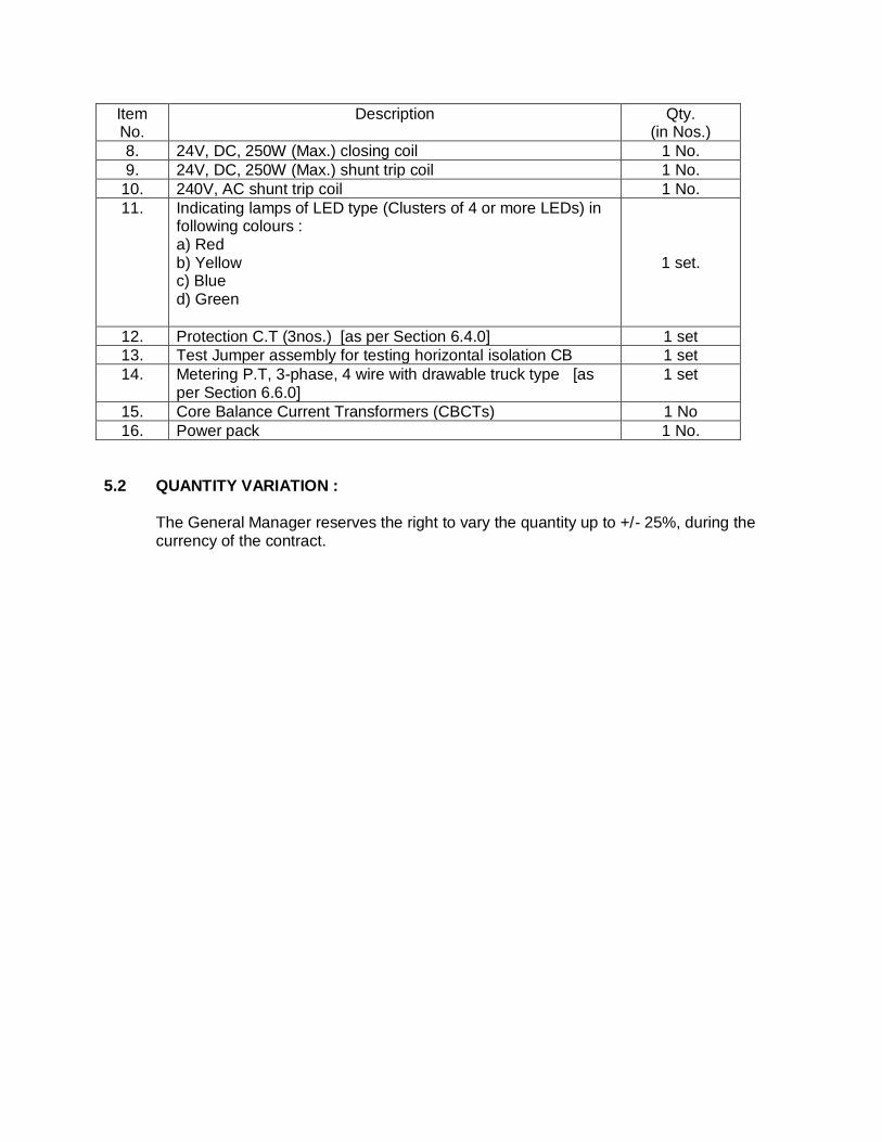
8. 24V, DC, 250W (Max.) closing coil 1 No.
9. 24V, DC, 250W (Max.) shunt trip coil 1 No.
10. 240V, AC shunt trip coil 1 No.
11. Indicating lamps of LED type (Clusters of 4 or more LEDs) in following colours : a) Red b) Yellow c) Blue d) Green
1 set.
12. Protection C.T (3nos.) [as per Section 6.4.0] 1 set
13. Test Jumper assembly for testing horizontal isolation CB 1 set
14. Metering P.T, 3-phase, 4 wire with drawable truck type [as per Section 6.6.0]
1 set
15. Core Balance Current Transformers (CBCTs) 1 No
16. Power pack 1 No.
5.2 QUANTITY VARIATION : The General Manager reserves the right to vary the quantity up to +/- 25%, during the
currency of the contract.
SECTION 6 : SPECIFICATIONS
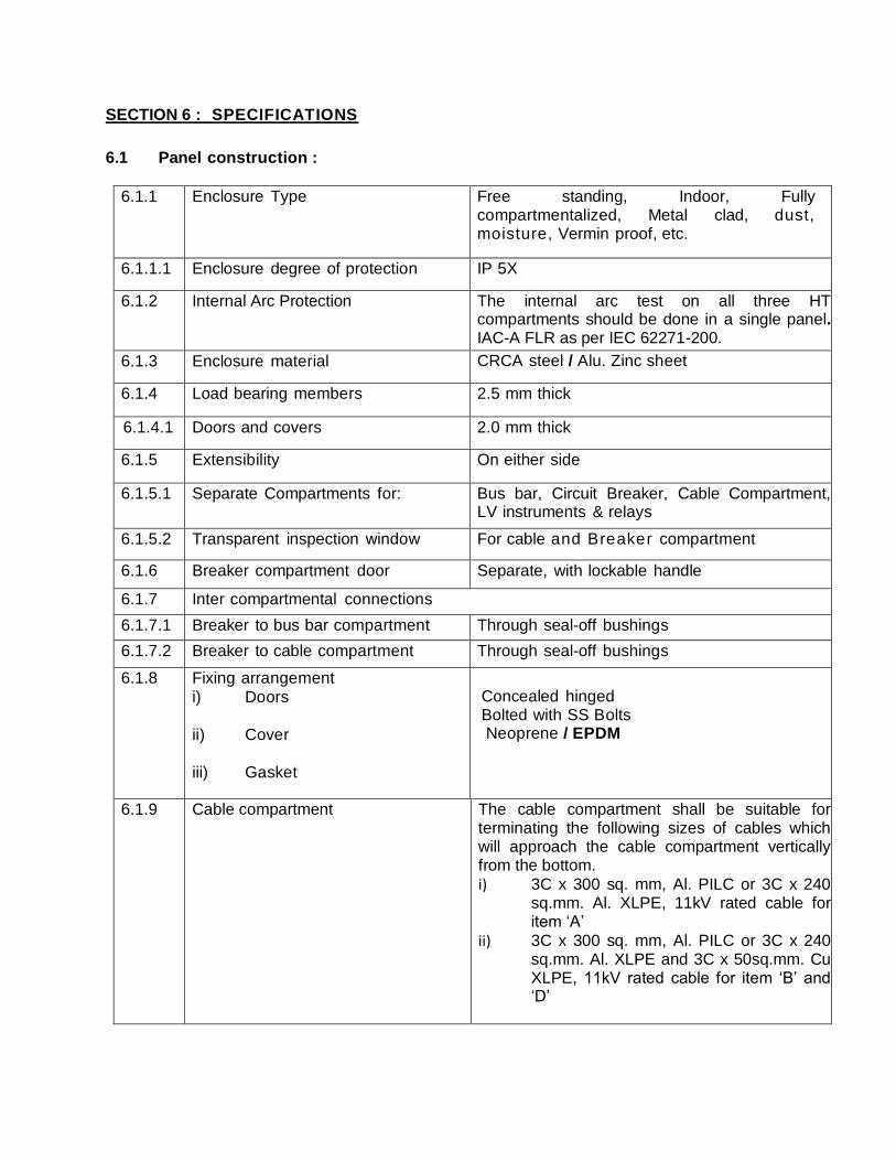
6.1 Panel construction :
6.1.1 Enclosure Type Free standing, Indoor, Fully compartmentalized, Metal clad, dust, moisture, Vermin proof, etc.
6.1.1.1 Enclosure degree of protection IP 5X
6.1.2 Internal Arc Protection The internal arc test on all three HT compartments should be done in a single panel. IAC-A FLR as per IEC 62271-200.
6.1.3 Enclosure material CRCA steel / Alu. Zinc sheet
6.1.4 Load bearing members 2.5 mm thick
6.1.4.1 Doors and covers 2.0 mm thick
6.1.5 Extensibility On either side
6.1.5.1 Separate Compartments for: Bus bar, Circuit Breaker, Cable Compartment, LV instruments & relays
6.1.5.2 Transparent inspection window For cable and Breaker compartment
6.1.6 Breaker compartment door Separate, with lockable handle
6.1.7 Inter compartmental connections
6.1.7.1 Breaker to bus bar compartment Through seal-off bushings
6.1.7.2 Breaker to cable compartment Through seal-off bushings
6.1.8
Fixing arrangement
i) Doors
ii) Cover
iii) Gasket
Concealed hinged Bolted with SS Bolts Neoprene / EPDM
6.1.9 Cable compartment The cable compartment shall be suitable for terminating the following sizes of cables which will approach the cable compartment vertically from the bottom.
i) 3C x 300 sq. mm, Al. PILC or 3C x 240 sq.mm. Al. XLPE, 11kV rated cable for item ‘A’
ii) 3C x 300 sq. mm, Al. PILC or 3C x 240 sq.mm. Al. XLPE and 3C x 50sq.mm. Cu XLPE, 11kV rated cable for item ‘B’ and ‘D’
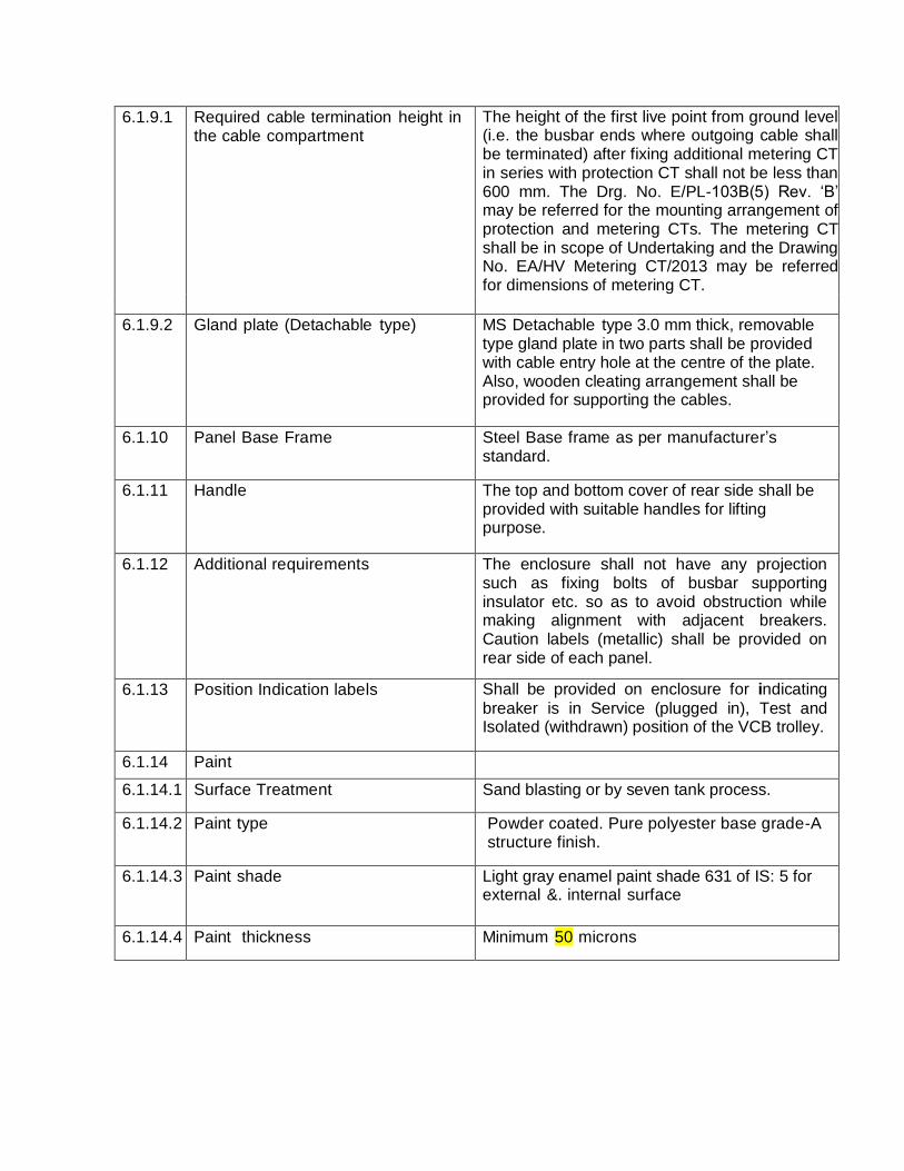
6.1.9.1 Required cable termination height in the cable compartment
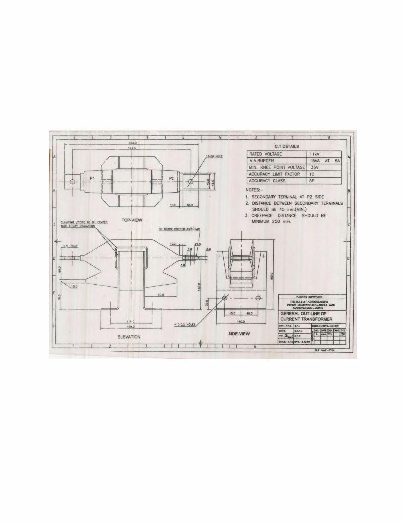
The height of the first live point from ground level (i.e. the busbar ends where outgoing cable shall be terminated) after fixing additional metering CT in series with protection CT shall not be less than 600 mm. The Drg. No. E/PL-103B(5) Rev. ‘B’ may be referred for the mounting arrangement of protection and metering CTs. The metering CT shall be in scope of Undertaking and the Drawing No. EA/HV Metering CT/2013 may be referred for dimensions of metering CT.
6.1.9.2 Gland plate (Detachable type) MS Detachable type 3.0 mm thick, removable type gland plate in two parts shall be provided with cable entry hole at the centre of the plate. Also, wooden cleating arrangement shall be provided for supporting the cables.
6.1.10 Panel Base Frame
Steel Base frame as per manufacturer’s standard.
6.1.11 Handle The top and bottom cover of rear side shall be provided with suitable handles for lifting purpose.
6.1.12 Additional requirements The enclosure shall not have any projection such as fixing bolts of busbar supporting insulator etc. so as to avoid obstruction while making alignment with adjacent breakers. Caution labels (metallic) shall be provided on rear side of each panel.
6.1.13 Position Indication labels Shall be provided on enclosure for indicating
breaker is in Service (plugged in), Test and Isolated (withdrawn) position of the VCB trolley.
6.1.14 Paint
6.1.14.1 Surface Treatment Sand blasting or by seven tank process.
6.1.14.2 Paint type Powder coated. Pure polyester base grade-A structure finish.
6.1.14.3 Paint shade Light gray enamel paint shade 631 of IS: 5 for external &. internal surface
6.1.14.4 Paint thickness Minimum 50 microns

6.2 Circuit breaker :
6.2.1 Mounting On withdrawable truck, with locking facility in service position.
6.2.2 Switching duty a)Transformer (oil filled and dry type) b)Underground 1 1 k V cable of various sizes viz: 3CX 240 sq.mm Al XLPE, 3CX 300sqmm Al PILC,3CX 50 sq.mm Cu XLPE cable etc.
6.2.3 Interrupting medium Vacuum
6.2.3.1 Make of Interrupter 1. The make of the interrupter would be same as the make of Circuit Breaker.
2. Or the make of interrupter shall be of following make :-
Crompton Greaves Ltd., ABB, Bharat Electronics Ltd, Schneider Electric, Siemens.
6.2.4 Breaker operation Three separate identical single pole units operated through the common shaft. The VCB shall be tested for E2 and M2 class.
6.2.5 Operating Mechanism Totally enclosed, self lubricating and spring operated type
Re-strike free, Trip free, with electrical anti- pumping feature.
One O-C-O operation possible after failure of power supply to the spring charging motor
Motor wound, spring charged, stored energy type with manual charging facility
6.2.6 Busbars Electrolytic copper material is used for busbars.
Shall be so arranged that, they can be extended in future without any difficulty.
Shall be of ample size and strength to withstand any mechanical stresses set up by short circuit currents.
Provision shall be made for variation of the temperature so that no undue expansion and contraction of the busbars with the mechanical stresses are imposed on the busbar insulators and supports.
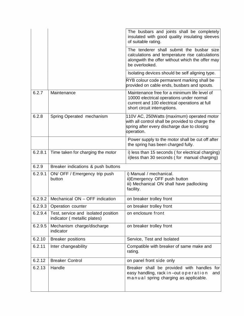
The busbars and joints shall be completely insulated with good quality insulating sleeves of suitable rating.
The tenderer shall submit the busbar size calculations and temperature rise calculations alongwith the offer without which the offer may be overlooked.
Isolating devices should be self aligning type.
RYB colour code permanent marking shall be provided on cable ends, busbars and spouts.
6.2.7 Maintenance Maintenance free for a minimum life level of 10000 electrical operations under normal current and 100 electrical operations at full short circuit interruptions.
6.2.8
Spring Operated mechanism 110V AC, 250Watts (maximum) operated motor with all control shall be provided to charge the spring after every discharge due to closing operation.
Power supply to the motor shall be cut off after the spring has been charged fully.
6.2.8.1 Time taken for charging the motor i) less than 15 seconds ( for electrical charging)
ii)less than 30 seconds ( for manual charging)
6.2.9 Breaker indications & push buttons
6.2.9.1 ON/ OFF / Emergency trip push button
i) Manual / mechanical. ii)Emergency OFF push button iii) Mechanical ON shall have padlocking facility.
6.2.9.2 Mechanical ON – OFF indication on breaker trolley front
6.2.9.3 Operation counter on breaker trolley front
6.2.9.4 Test, service and isolated position indicator ( metallic plates)
on enclosure front
6.2.9.5 Mechanism charge/discharge indicator
on breaker trolley front
6.2.10 Breaker positions Service, Test and Isolated
6.2.11 Inter changeability Compatible with breaker of same make and rating.
6.2.12 Breaker Control on panel front side only
6.2.13 Handle Breaker shall be provided with handles for easy handling, rack i n –out o p e r a t i o n and m a n u a l spring charging as applicable.
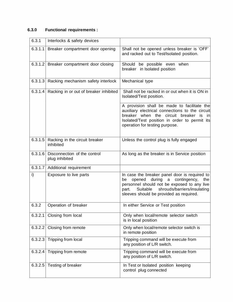
6.3.0 Functional requirements :
6.3.1 Interlocks & safety devices
6.3.1.1 Breaker compartment door opening Shall not be opened unless breaker is ‘OFF’ and racked out to Test/Isolated position.
6.3.1.2 Breaker compartment door closing Should be possible even when breaker in Isolated position
6.3.1.3 Racking mechanism safety interlock Mechanical type
6.3.1.4 Racking in or out of breaker inhibited Shall not be racked in or out when it is ON in Isolated/Test position.
A provision shall be made to facilitate the auxiliary electrical connections to the circuit breaker when the circuit breaker is in Isolated/Test position in order to permit its operation for testing purpose.
6.3.1.5 Racking in the circuit breaker inhibited
Unless the control plug is fully engaged
6.3.1.6 Disconnection of the control plug inhibited
As long as the breaker is in Service position
6.3.1.7 Additional requirement
i) Exposure to live parts In case the breaker panel door is required to be opened during a contingency, the personnel should not be exposed to any live part. Suitable shrouds/barriers/insulating sleeves should be provided as required.
6.3.2 Operation of breaker In either Service or Test position
6.3.2.1 Closing from local Only when local/remote selector switch is in local position
6.3.2.2 Closing from remote Only when local/remote selector switch is in remote position
6.3.2.3 Tripping from local Tripping command will be execute from any position of L/R switch.
6.3.2.4 Tripping from remote Tripping command will be execute from any position of L/R switch.
6.3.2.5 Testing of breaker In Test or Isolated position keeping control plug connected
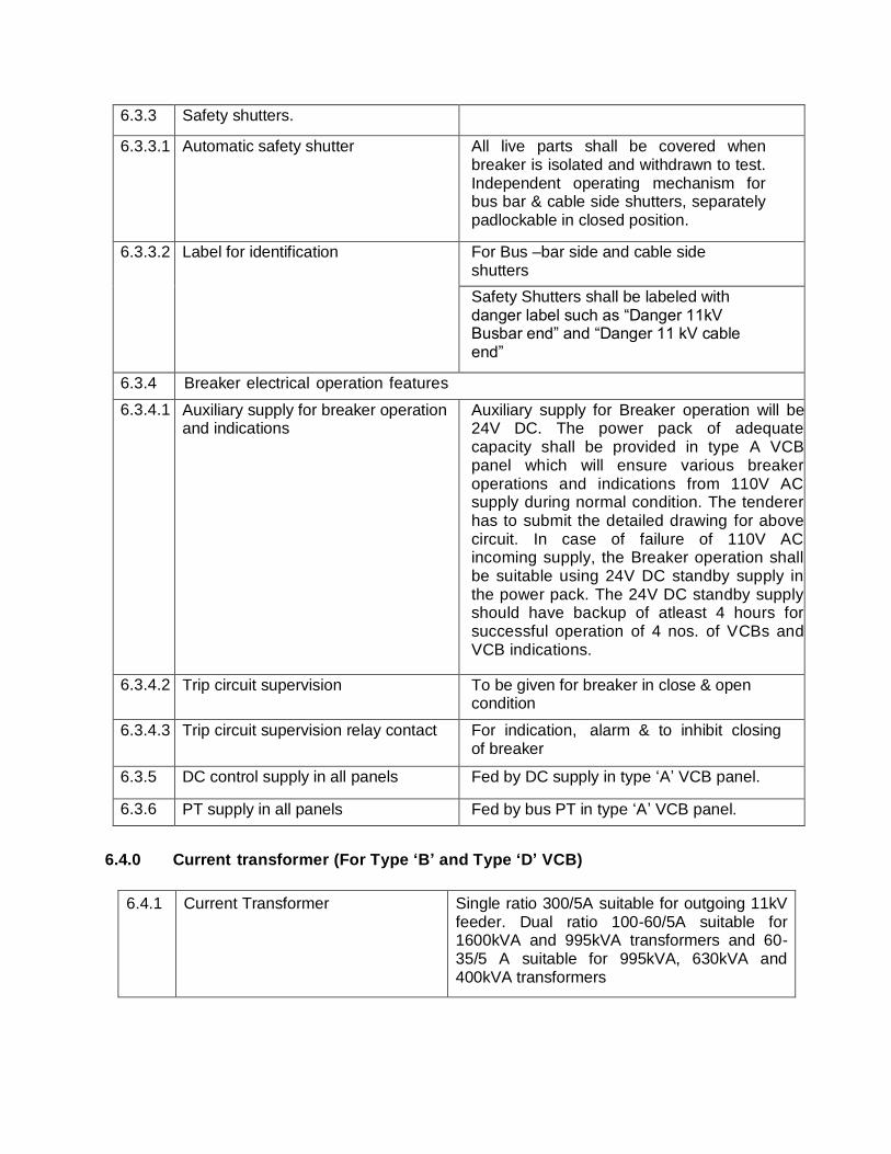
6.3.3 Safety shutters.
6.3.3.1 Automatic safety shutter All live parts shall be covered when breaker is isolated and withdrawn to test. Independent operating mechanism for bus bar & cable side shutters, separately padlockable in closed position.
6.3.3.2 Label for identification For Bus –bar side and cable side shutters
Safety Shutters shall be labeled with danger label such as “Danger 11kV Busbar end” and “Danger 11 kV cable end”
6.3.4 Breaker electrical operation features
6.3.4.1 Auxiliary supply for breaker operation and indications
Auxiliary supply for Breaker operation will be 24V DC. The power pack of adequate capacity shall be provided in type A VCB panel which will ensure various breaker operations and indications from 110V AC supply during normal condition. The tenderer has to submit the detailed drawing for above circuit. In case of failure of 110V AC incoming supply, the Breaker operation shall be suitable using 24V DC standby supply in the power pack. The 24V DC standby supply should have backup of atleast 4 hours for successful operation of 4 nos. of VCBs and VCB indications.
6.3.4.2 Trip circuit supervision To be given for breaker in close & open condition
6.3.4.3 Trip circuit supervision relay contact For indication, alarm & to inhibit closing of breaker
6.3.5 DC control supply in all panels Fed by DC supply in type ‘A’ VCB panel.
6.3.6 PT supply in all panels Fed by bus PT in type ‘A’ VCB panel.
6.4.0 Current transformer (For Type ‘B’ and Type ‘D’ VCB)
6.4.1 Current Transformer Single ratio 300/5A suitable for outgoing 11kV feeder. Dual ratio 100-60/5A suitable for 1600kVA and 995kVA transformers and 60-35/5 A suitable for 995kVA, 630kVA and 400kVA transformers
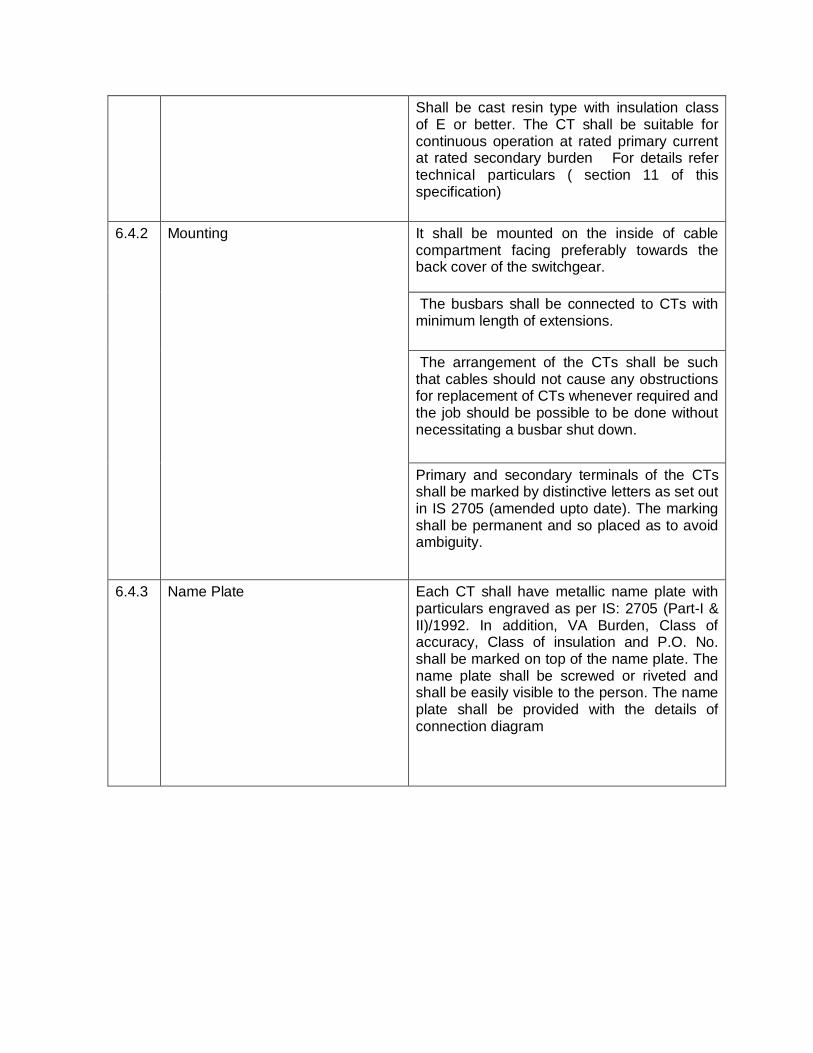
Shall be cast resin type with insulation class of E or better. The CT shall be suitable for continuous operation at rated primary current at rated secondary burden For details refer technical particulars ( section 11 of this specification)
6.4.2 Mounting It shall be mounted on the inside of cable compartment facing preferably towards the back cover of the switchgear.
The busbars shall be connected to CTs with minimum length of extensions.
The arrangement of the CTs shall be such that cables should not cause any obstructions for replacement of CTs whenever required and the job should be possible to be done without necessitating a busbar shut down.
Primary and secondary terminals of the CTs shall be marked by distinctive letters as set out in IS 2705 (amended upto date). The marking shall be permanent and so placed as to avoid ambiguity.
6.4.3 Name Plate Each CT shall have metallic name plate with particulars engraved as per IS: 2705 (Part-I & II)/1992. In addition, VA Burden, Class of accuracy, Class of insulation and P.O. No. shall be marked on top of the name plate. The name plate shall be screwed or riveted and shall be easily visible to the person. The name plate shall be provided with the details of connection diagram
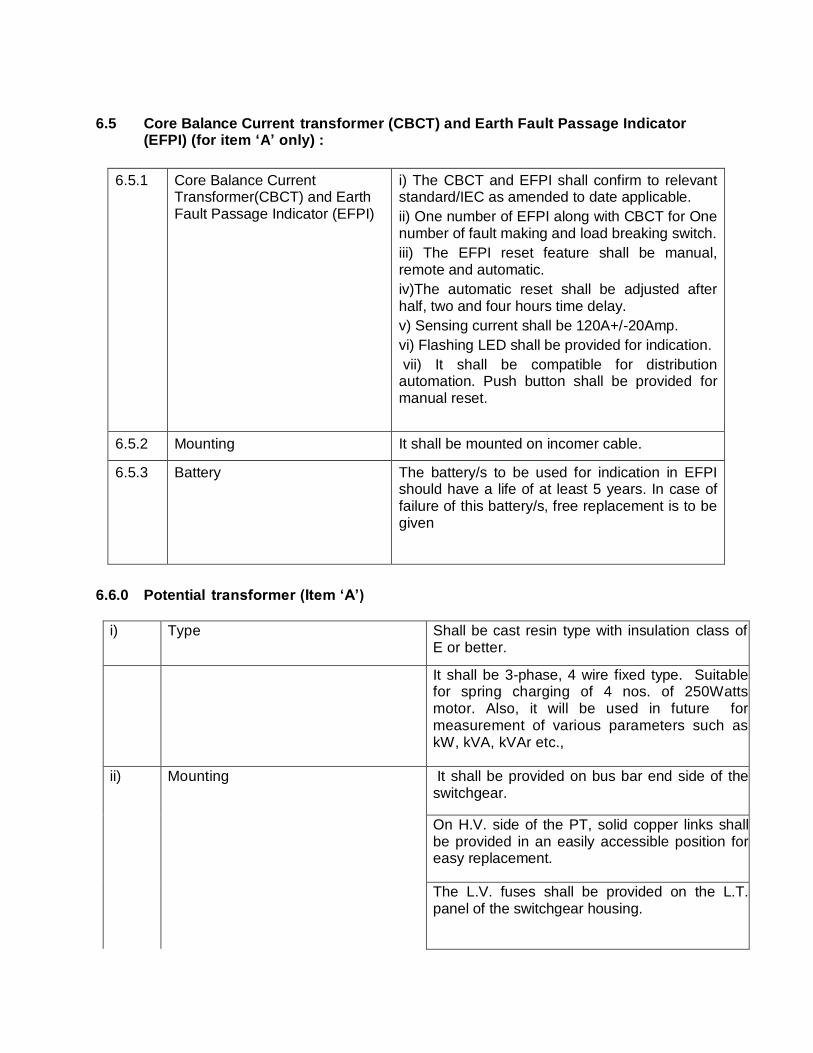
6.5 Core Balance Current transformer (CBCT) and Earth Fault Passage Indicator (EFPI) (for item ‘A’ only) :
6.5.1 Core Balance Current Transformer(CBCT) and Earth Fault Passage Indicator (EFPI)
i) The CBCT and EFPI shall confirm to relevant standard/IEC as amended to date applicable.
ii) One number of EFPI along with CBCT for One number of fault making and load breaking switch.
iii) The EFPI reset feature shall be manual, remote and automatic.
iv)The automatic reset shall be adjusted after half, two and four hours time delay.
v) Sensing current shall be 120A+/-20Amp.
vi) Flashing LED shall be provided for indication.
vii) It shall be compatible for distribution automation. Push button shall be provided for manual reset.
6.5.2 Mounting It shall be mounted on incomer cable.
6.5.3 Battery The battery/s to be used for indication in EFPI should have a life of at least 5 years. In case of failure of this battery/s, free replacement is to be given
6.6.0 Potential transformer (Item ‘A’)
i) Type Shall be cast resin type with insulation class of E or better.
It shall be 3-phase, 4 wire fixed type. Suitable for spring charging of 4 nos. of 250Watts motor. Also, it will be used in future for measurement of various parameters such as kW, kVA, kVAr etc.,
ii) Mounting It shall be provided on bus bar end side of the switchgear. On H.V. side of the PT, solid copper links shall be provided in an easily accessible position for easy replacement.
The L.V. fuses shall be provided on the L.T. panel of the switchgear housing.
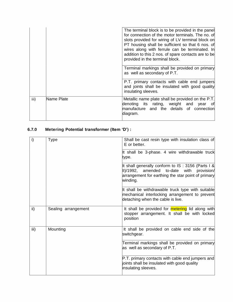
The terminal block is to be provided in the panel for connection of the motor terminals. The no. of slots provided for wiring of LV terminal block on PT housing shall be sufficient so that 6 nos. of wires along with ferrule can be terminated. In addition to this 2 nos. of spare contacts are to be provided in the terminal block.
Terminal markings shall be provided on primary as well as secondary of P.T.
P.T. primary contacts with cable end jumpers and joints shall be insulated with good quality insulating sleeves.
iii) Name Plate Metallic name plate shall be provided on the P.T. denoting its rating, weight and year of manufacture and the details of connection diagram.
6.7.0 Metering Potential transformer (Item ‘D’) :
i) Type Shall be cast resin type with insulation class of E or better.
It shall be 3-phase. 4 wire withdrawable truck type.
It shall generally conform to IS : 3156 (Parts I & II)/1992, amended to-date with provision/ arrangement for earthing the star point of primary winding.
It shall be withdrawable truck type with suitable mechanical interlocking arrangement to prevent detaching when the cable is live.
ii) Sealing arrangement It shall be provided for metering lid along with stopper arrangement. It shall be with locked position
iii) Mounting It shall be provided on cable end side of the switchgear.
Terminal markings shall be provided on primary as well as secondary of P.T.
P.T. primary contacts with cable end jumpers and joints shall be insulated with good quality insulating sleeves.
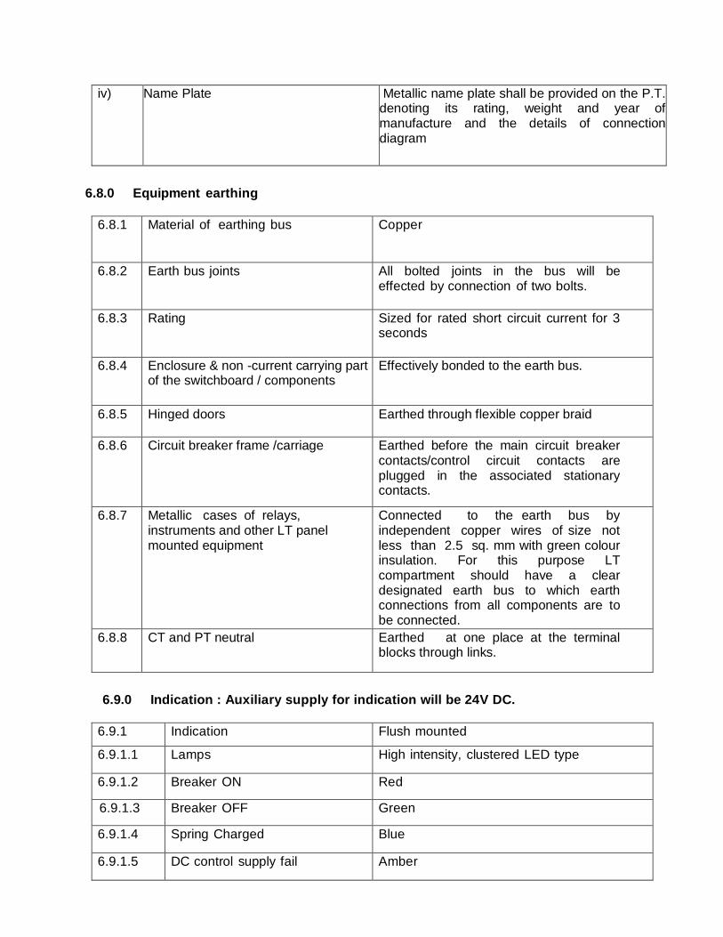
iv) Name Plate Metallic name plate shall be provided on the P.T. denoting its rating, weight and year of manufacture and the details of connection diagram
6.8.0 Equipment earthing
6.8.1 Material of earthing bus Copper
6.8.2 Earth bus joints All bolted joints in the bus will be effected by connection of two bolts.
6.8.3 Rating Sized for rated short circuit current for 3 seconds
6.8.4 Enclosure & non -current carrying part of the switchboard / components
Effectively bonded to the earth bus.
6.8.5 Hinged doors Earthed through flexible copper braid
6.8.6 Circuit breaker frame /carriage Earthed before the main circuit breaker contacts/control circuit contacts are plugged in the associated stationary contacts.
6.8.7 Metallic cases of relays, instruments and other LT panel mounted equipment
Connected to the earth bus by independent copper wires of size not less than 2.5 sq. mm with green colour insulation. For this purpose LT compartment should have a clear designated earth bus to which earth connections from all components are to be connected.
6.8.8 CT and PT neutral Earthed at one place at the terminal blocks through links.
6.9.0 Indication : Auxiliary supply for indication will be 24V DC.
6.9.1 Indication Flush mounted
6.9.1.1 Lamps High intensity, clustered LED type
6.9.1.2 Breaker ON Red
6.9.1.3 Breaker OFF Green
6.9.1.4 Spring Charged Blue
6.9.1.5 DC control supply fail Amber
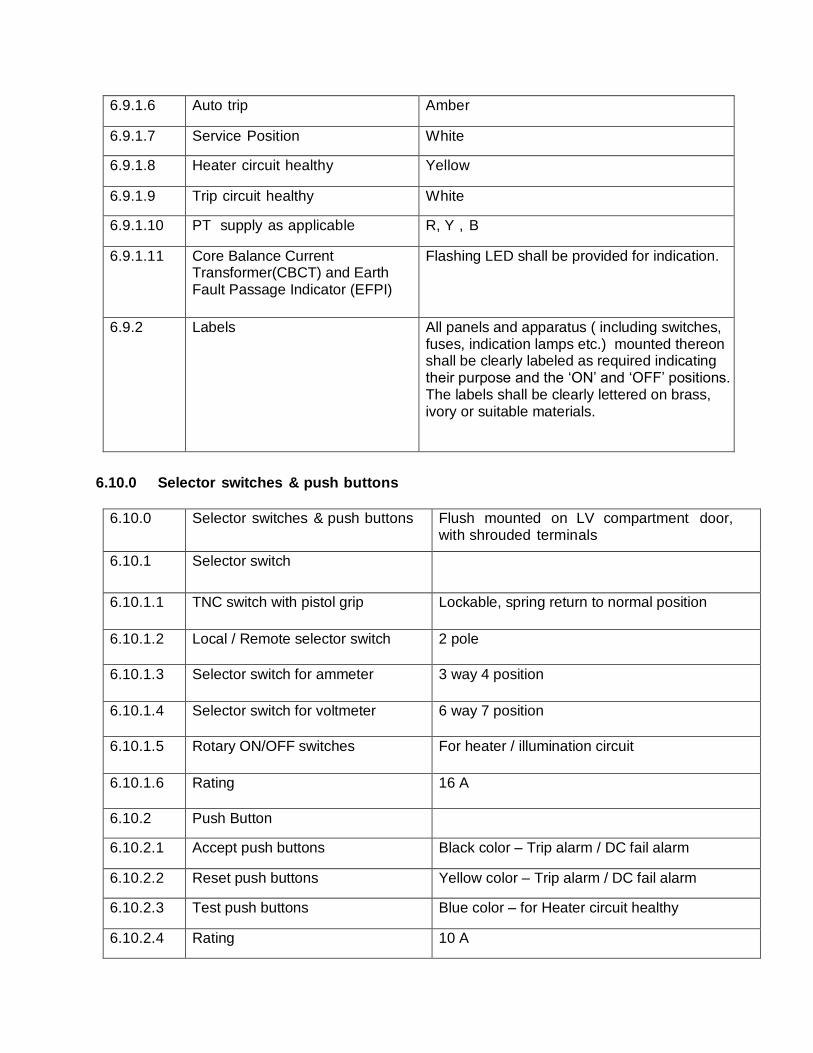
6.9.1.6 Auto trip Amber
6.9.1.7 Service Position White
6.9.1.8 Heater circuit healthy Yellow
6.9.1.9 Trip circuit healthy White
6.9.1.10 PT supply as applicable R, Y , B
6.9.1.11 Core Balance Current Transformer(CBCT) and Earth Fault Passage Indicator (EFPI)
Flashing LED shall be provided for indication.
6.9.2 Labels All panels and apparatus ( including switches, fuses, indication lamps etc.) mounted thereon shall be clearly labeled as required indicating their purpose and the ‘ON’ and ‘OFF’ positions. The labels shall be clearly lettered on brass, ivory or suitable materials.
6.10.0 Selector switches & push buttons
6.10.0 Selector switches & push buttons Flush mounted on LV compartment door, with shrouded terminals
6.10.1 Selector switch
6.10.1.1 TNC switch with pistol grip Lockable, spring return to normal position
6.10.1.2 Local / Remote selector switch 2 pole
6.10.1.3 Selector switch for ammeter 3 way 4 position
6.10.1.4 Selector switch for voltmeter 6 way 7 position
6.10.1.5 Rotary ON/OFF switches For heater / illumination circuit
6.10.1.6 Rating 16 A
6.10.2 Push Button
6.10.2.1 Accept push buttons Black color – Trip alarm / DC fail alarm
6.10.2.2 Reset push buttons Yellow color – Trip alarm / DC fail alarm
6.10.2.3 Test push buttons Blue color – for Heater circuit healthy
6.10.2.4 Rating 10 A
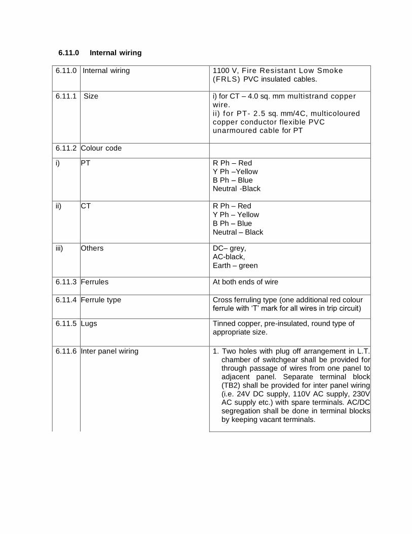
6.11.0 Internal wiring
6.11.0 Internal wiring 1100 V, Fire Resistant Low Smoke (FRLS) PVC insulated cables.
6.11.1 Size i) for CT – 4.0 sq. mm multistrand copper wire.
i i) for PT- 2.5 sq. mm/4C, multicoloured copper conductor flexible PVC unarmoured cable for PT
6.11.2 Colour code
i) PT R Ph – Red Y Ph –Yellow B Ph – Blue Neutral -Black
ii) CT R Ph – Red
Y Ph – Yellow
B Ph – Blue
Neutral – Black
iii) Others DC– grey, AC-black,
Earth – green
6.11.3 Ferrules At both ends of wire
6.11.4 Ferrule type Cross ferruling type (one additional red colour ferrule with ‘T’ mark for all wires in trip circuit)
6.11.5 Lugs Tinned copper, pre-insulated, round type of appropriate size.
6.11.6 Inter panel wiring 1. Two holes with plug off arrangement in L.T. chamber of switchgear shall be provided for through passage of wires from one panel to adjacent panel. Separate terminal block (TB2) shall be provided for inter panel wiring (i.e. 24V DC supply, 110V AC supply, 230V AC supply etc.) with spare terminals. AC/DC segregation shall be done in terminal blocks by keeping vacant terminals.
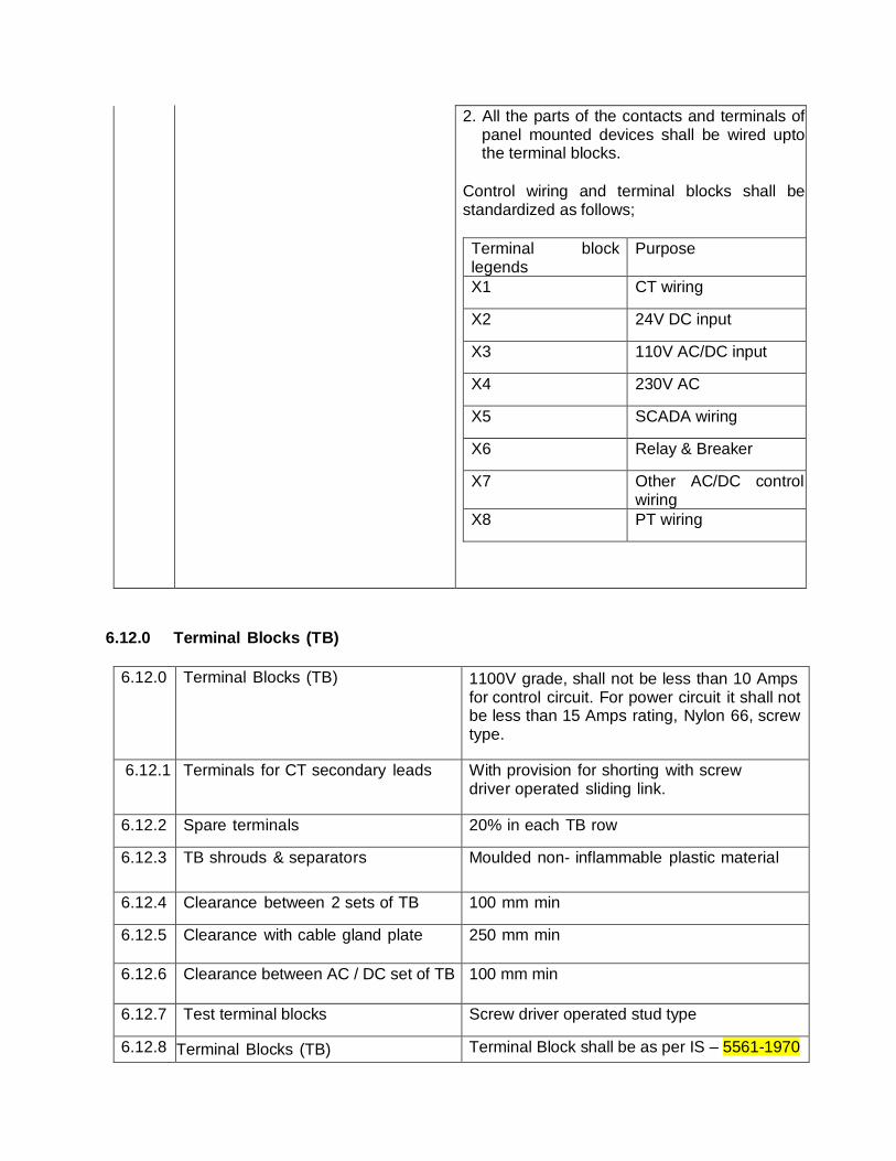
2. All the parts of the contacts and terminals of panel mounted devices shall be wired upto the terminal blocks.
Control wiring and terminal blocks shall be standardized as follows;
Terminal block legends
Purpose
X1 CT wiring
X2 24V DC input
X3 110V AC/DC input
X4 230V AC
X5 SCADA wiring
X6 Relay & Breaker
X7 Other AC/DC control wiring
X8 PT wiring
6.12.0 Terminal Blocks (TB)
6.12.0 Terminal Blocks (TB) 1100V grade, shall not be less than 10 Amps for control circuit. For power circuit it shall not be less than 15 Amps rating, Nylon 66, screw type.
6.12.1 Terminals for CT secondary leads With provision for shorting with screw driver operated sliding link.
6.12.2 Spare terminals 20% in each TB row
6.12.3 TB shrouds & separators Moulded non- inflammable plastic material
6.12.4 Clearance between 2 sets of TB 100 mm min
6.12.5 Clearance with cable gland plate 250 mm min
6.12.6 Clearance between AC / DC set of TB 100 mm min
6.12.7 Test terminal blocks Screw driver operated stud type
6.12.8 Terminal Blocks (TB)
Terminal Block shall be as per IS – 5561-1970

6.13.0 Meters
6.13.0 Meters Flush mounted
6.13.1 Ammeter Taut band/pivot, moving iron type
6.13.1.1 Size 96x96 mm
6.13.1.2 Panels where to be provided For Type B & D panels only.
6.13.1.3 Ammeter selector switch To be provided
6.13.1.4 Accuracy Class 1.0
6.13.2 Voltmeter Taut band/pivot, moving iron type
6.13.2.1 Size 96x96 mm
6.13.2.2 Panels where to be provided For Type A & D panels only..
6.13.2.3 Voltmeter switch To be provided
6.13.2.4 Accuracy Class 1.0
6.14.0 Locking arrangements
6.14.0 Locking arrangement Shall be provided as stated below :
a) Circuit breaker shall not be racked in and racked out when it is ‘ON’ in Isolated/ Test position.
b) The circuit breaker shall be provided with facility to lock the individual switchgear assembly physically inside the housing itself in order to avoid theft. Extra 3 key sets are to be provided along with the locking arrangement.
c) Circuit breaker shall not be switched in unless it is in service (plugged in) and test/ isolated (withdrawn) position.
6.14.1 Foundations bolts All foundation bolts, nuts and washers necessary for installation shall be supplied. It shall be possible to put the ragbolts after the switchgear is positioned on its foundation.
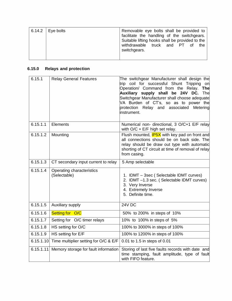
6.14.2 Eye bolts Removable eye bolts shall be provided to facilitate the handling of the switchgears. Suitable lifting hooks shall be provided to the withdrawable truck and PT of the switchgears.
6.15.0 Relays and protection
6.15.1 Relay General Features The switchgear Manufacturer shall design the trip coil for successful Shunt Tripping on Operation/ Command from the Relay. The Auxiliary supply shall be 24V DC. The
Switchgear Manufacturer shall choose adequate VA Burden of CT’s, so as to power the protection Relay and associated Metering instrument.
6.15.1.1 Elements Numerical non- directional, 3 O/C+1 E/F relay with O/C + E/F high set relay.
6.15.1.2 Mounting Flush mounted, IP5X with key pad on front and all connections should be on back side. The relay should be draw out type with automatic shorting of CT circuit at time of removal of relay from casing.
6.15.1.3 CT secondary input current to relay 5 Amp selectable
6.15.1.4 Operating characteristics (Selectable)
1. IDMT – 3sec ( Selectable IDMT curves) 2. IDMT –1.3 sec. ( Selectable IDMT curves) 3. Very Inverse 4. Extremely Inverse 5. Definite time.
6.15.1.5 Auxiliary supply 24V DC
6.15.1.6 Setting for O/C 50% to 200% in steps of 10%
6.15.1.7 Setting for O/C timer relays 10% to 100% in steps of 5%
6.15.1.8 HS setting for O/C 100% to 3000% in steps of 100%
6.15.1.9 HS setting for E/F 100% to 1200% in steps of 100%
6.15.1.10 Time multiplier setting for O/C & E/F 0.01 to 1.5 in steps of 0.01
6.15.1.11 Memory storage for fault information Storing of last five faults records with date and time stamping, fault amplitude, type of fault with FIFO feature.
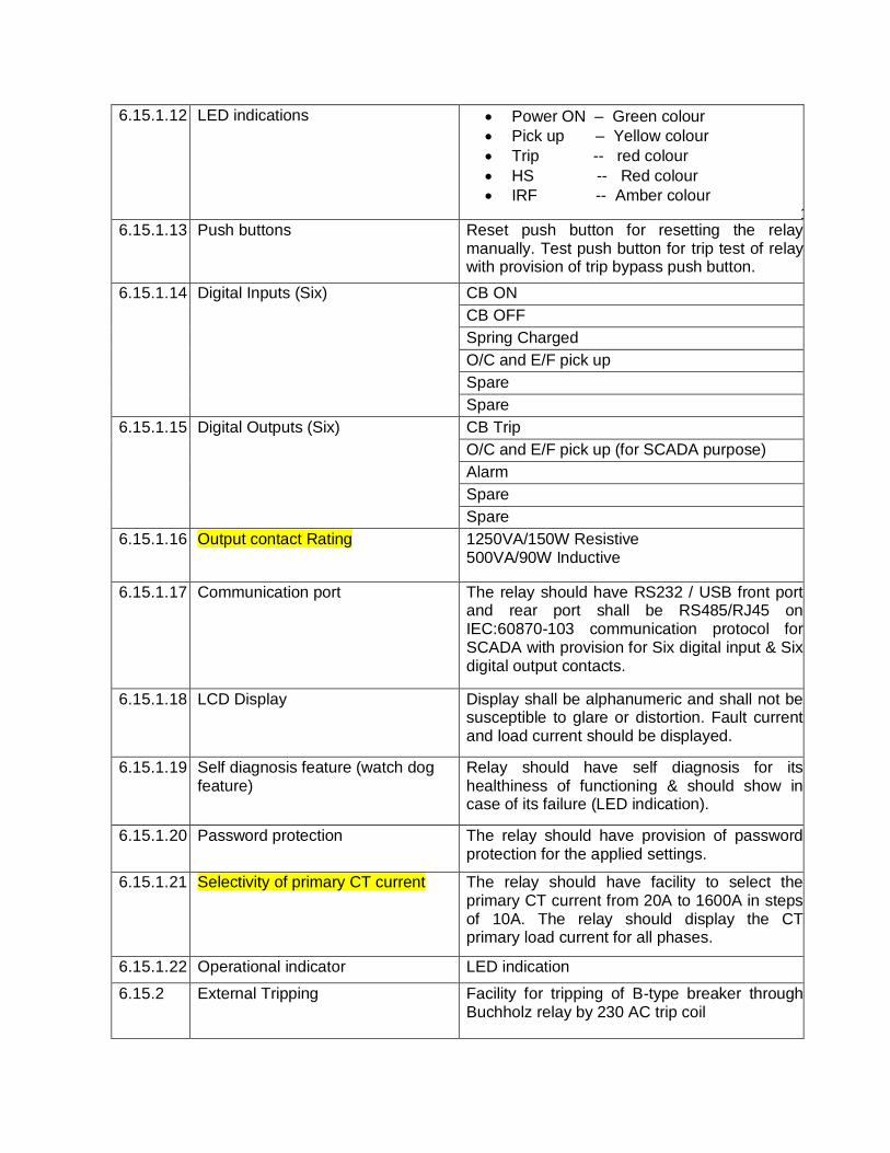
6.15.1.12 LED indications Power ON – Green colour
Pick up – Yellow colour
Trip -- red colour
HS -- Red colour
IRF -- Amber colour 1.
6.15.1.13 Push buttons Reset push button for resetting the relay manually. Test push button for trip test of relay with provision of trip bypass push button.
6.15.1.14 Digital Inputs (Six) CB ON
CB OFF
Spring Charged
O/C and E/F pick up
Spare
Spare
6.15.1.15 Digital Outputs (Six) CB Trip
O/C and E/F pick up (for SCADA purpose)
Alarm
Spare
Spare
6.15.1.16 Output contact Rating 1250VA/150W Resistive 500VA/90W Inductive
6.15.1.17 Communication port The relay should have RS232 / USB front port and rear port shall be RS485/RJ45 on IEC:60870-103 communication protocol for SCADA with provision for Six digital input & Six digital output contacts.
6.15.1.18 LCD Display Display shall be alphanumeric and shall not be susceptible to glare or distortion. Fault current and load current should be displayed.
6.15.1.19 Self diagnosis feature (watch dog feature)
Relay should have self diagnosis for its healthiness of functioning & should show in case of its failure (LED indication).
6.15.1.20 Password protection The relay should have provision of password protection for the applied settings.
6.15.1.21 Selectivity of primary CT current
The relay should have facility to select the primary CT current from 20A to 1600A in steps of 10A. The relay should display the CT primary load current for all phases.
6.15.1.22 Operational indicator LED indication
6.15.2 External Tripping Facility for tripping of B-type breaker through Buchholz relay by 230 AC trip coil
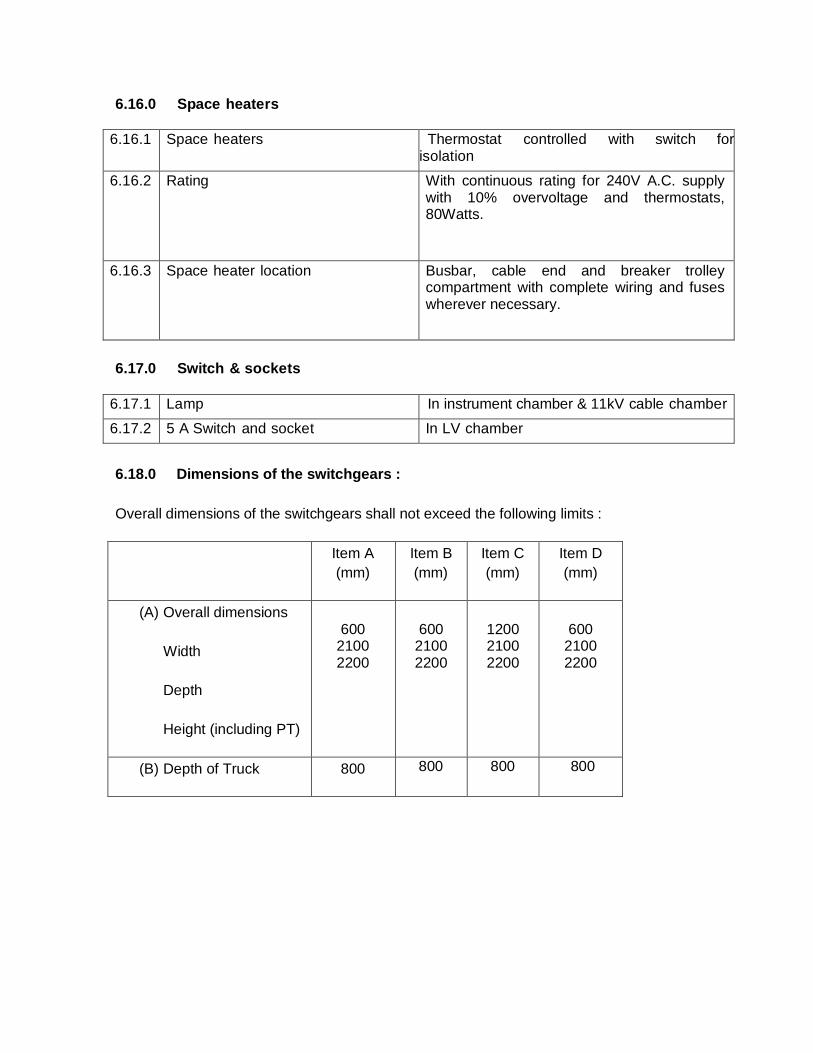
6.16.0 Space heaters
6.16.1 Space heaters Thermostat controlled with switch for isolation
6.16.2 Rating With continuous rating for 240V A.C. supply with 10% overvoltage and thermostats, 80Watts.
6.16.3 Space heater location Busbar, cable end and breaker trolley compartment with complete wiring and fuses wherever necessary.
6.17.0 Switch & sockets
6.17.1 Lamp In instrument chamber & 11kV cable chamber
6.17.2 5 A Switch and socket In LV chamber
6.18.0 Dimensions of the switchgears :
Overall dimensions of the switchgears shall not exceed the following limits :
Item A
(mm)
Item B
(mm)
Item C
(mm)
Item D
(mm)
(A) Overall dimensions
Width
Depth
Height (including PT)
600
2100 2200
600
2100 2200
1200 2100 2200
600
2100 2200
(B) Depth of Truck
800 800 800 800
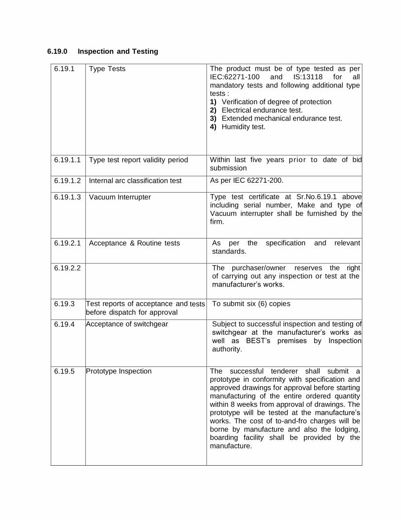
6.19.0 Inspection and Testing
6.19.1 Type Tests The product must be of type tested as per IEC:62271-100 and IS:13118 for all mandatory tests and following additional type tests : 1) Verification of degree of protection 2) Electrical endurance test. 3) Extended mechanical endurance test. 4) Humidity test.
6.19.1.1 Type test report validity period Within last five years prior to date of bid submission
6.19.1.2 Internal arc classification test As per IEC 62271-200.
6.19.1.3 Vacuum Interrupter Type test certificate at Sr.No.6.19.1 above including serial number, Make and type of Vacuum interrupter shall be furnished by the firm.
6.19.2.1 Acceptance & Routine tests As per the specification and relevant standards.
6.19.2.2 The purchaser/owner reserves the right of carrying out any inspection or test at the manufacturer’s works.
6.19.3 Test reports of acceptance and tests before dispatch for approval
To submit six (6) copies
6.19.4 Acceptance of switchgear Subject to successful inspection and testing of switchgear at the manufacturer’s works as well as BEST’s premises by Inspection authority.
6.19.5 Prototype Inspection The successful tenderer shall submit a prototype in conformity with specification and approved drawings for approval before starting manufacturing of the entire ordered quantity within 8 weeks from approval of drawings. The prototype will be tested at the manufacture’s works. The cost of to-and-fro charges will be borne by manufacture and also the lodging, boarding facility shall be provided by the manufacture.
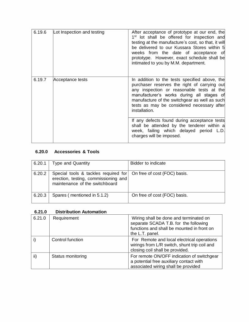
6.19.6 Lot Inspection and testing After acceptance of prototype at our end, the 1st lot shall be offered for inspection and testing at the manufacture’s cost, so that, it will be delivered to our Kussara Stores within 5 weeks from the date of acceptance of prototype. However, exact schedule shall be intimated to you by M.M. department.
6.19.7
Acceptance tests In addition to the tests specified above, the purchaser reserves the right of carrying out any inspection or reasonable tests at the manufacturer’s works during all stages of manufacture of the switchgear as well as such tests as may be considered necessary after installation.
If any defects found during acceptance tests shall be attended by the tenderer within a week, failing which delayed period L.D. charges will be imposed.
6.20.0 Accessories & Tools
6.20.1 Type and Quantity Bidder to indicate
6.20.2 Special tools & tackles required for erection, testing, commissioning and maintenance of the switchboard
On free of cost (FOC) basis.
6.20.3 Spares ( mentioned in 5.1.2) On free of cost (FOC) basis.
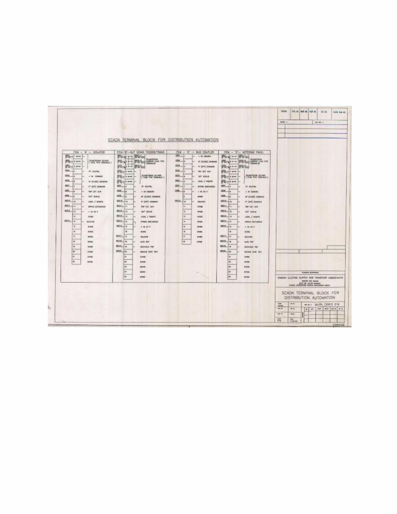
6.21.0 Distribution Automation
6.21.0 Requirement Wiring shall be done and terminated on separate SCADA T.B. for the following functions and shall be mounted in front on the L.T. panel.
i) Control function For Remote and local electrical operations wirings from L/R switch, shunt trip coil and closing coil shall be provided.
ii) Status monitoring For remote ON/OFF indication of switchgear a potential free auxiliary contact with associated wiring shall be provided
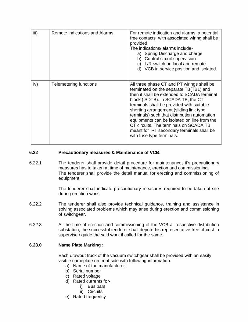
iii) Remote indications and Alarms For remote indication and alarms, a potential free contacts with associated wiring shall be provided The indications/ alarms include-
a) Spring Discharge and charge b) Control circuit supervision c) L/R switch on local and remote d) VCB in service position and isolated.
iv) Telemetering functions All three phase CT and PT wirings shall be terminated on the separate TB(TB1) and then it shall be extended to SCADA terminal block ( SDTB). In SCADA TB, the CT terminals shall be provided with suitable shorting arrangement (sliding link type terminals) such that distribution automation equipments can be isolated on line from the CT circuits. The terminals on SCADA TB meant for PT secondary terminals shall be with fuse type terminals.
6.22 Precautionary measures & Maintenance of VCB:
6.22.1 The tenderer shall provide detail procedure for maintenance, it’s precautionary measures has to taken at time of maintenance, erection and commissioning.
The tenderer shall provide the detail manual for erecting and commissioning of equipment. The tenderer shall indicate precautionary measures required to be taken at site during erection work.
6.22.2 The tenderer shall also provide technical guidance, training and assistance in solving associated problems which may arise during erection and commissioning of switchgear.
6.22.3 At the time of erection and commissioning of the VCB at respective distribution
substation, the successful tenderer shall depute his representative free of cost to supervise / guide the said work if called for the same.
6.23.0 Name Plate Marking :
Each drawout truck of the vacuum switchgear shall be provided with an easily visible nameplate on front side with following information.
a) Name of the manufacturer. b) Serial number c) Rated voltage d) Rated currents for-
i) Bus bars ii) Circuits
e) Rated frequency
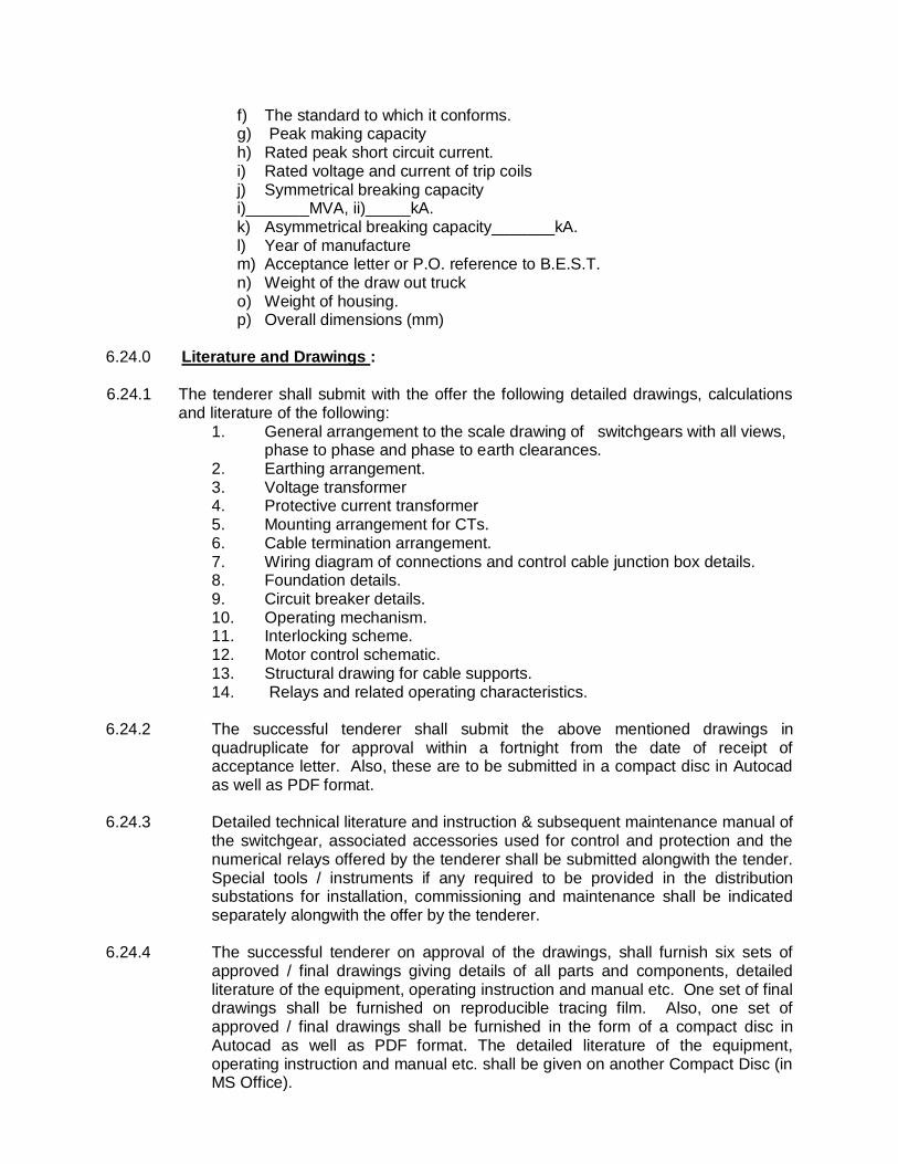
f) The standard to which it conforms. g) Peak making capacity h) Rated peak short circuit current. i) Rated voltage and current of trip coils j) Symmetrical breaking capacity i)_______MVA, ii)_____kA. k) Asymmetrical breaking capacity_______kA. l) Year of manufacture m) Acceptance letter or P.O. reference to B.E.S.T. n) Weight of the draw out truck o) Weight of housing. p) Overall dimensions (mm)
6.24.0 Literature and Drawings :
6.24.1 The tenderer shall submit with the offer the following detailed drawings, calculations and literature of the following:
1. General arrangement to the scale drawing of switchgears with all views, phase to phase and phase to earth clearances.
2. Earthing arrangement. 3. Voltage transformer 4. Protective current transformer 5. Mounting arrangement for CTs.
6. Cable termination arrangement. 7. Wiring diagram of connections and control cable junction box details.
8. Foundation details. 9. Circuit breaker details. 10. Operating mechanism. 11. Interlocking scheme. 12. Motor control schematic. 13. Structural drawing for cable supports. 14. Relays and related operating characteristics.
6.24.2 The successful tenderer shall submit the above mentioned drawings in quadruplicate for approval within a fortnight from the date of receipt of acceptance letter. Also, these are to be submitted in a compact disc in Autocad as well as PDF format.
6.24.3 Detailed technical literature and instruction & subsequent maintenance manual of
the switchgear, associated accessories used for control and protection and the numerical relays offered by the tenderer shall be submitted alongwith the tender. Special tools / instruments if any required to be provided in the distribution substations for installation, commissioning and maintenance shall be indicated separately alongwith the offer by the tenderer.
6.24.4 The successful tenderer on approval of the drawings, shall furnish six sets of
approved / final drawings giving details of all parts and components, detailed literature of the equipment, operating instruction and manual etc. One set of final drawings shall be furnished on reproducible tracing film. Also, one set of approved / final drawings shall be furnished in the form of a compact disc in Autocad as well as PDF format. The detailed literature of the equipment, operating instruction and manual etc. shall be given on another Compact Disc (in MS Office).
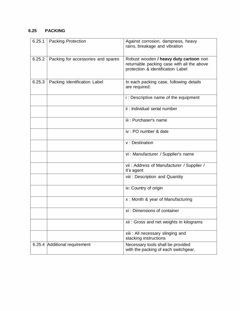
6.25 PACKING
6.25.1 Packing Protection Against corrosion, dampness, heavy rains, breakage and vibration
6.25.2 Packing for accessories and spares Robust wooden / heavy duty cartoon non
returnable packing case with all the above protection & identification Label
6.25.3 Packing Identification Label In each packing case, following details are required:
i : Descriptive name of the equipment
ii : Individual serial number
iii : Purchaser's name
iv : PO number & date
v : Destination
vi : Manufacturer / Supplier's name
vii : Address of Manufacturer / Supplier / it’s agent
viii : Description and Quantity
ix: Country of origin
x : Month & year of Manufacturing
xi : Dimensions of container
xii : Gross and net weights in kilograms
xiii : All necessary slinging and stacking instructions
6.25.4 Additional requirement Necessary tools shall be provided with the packing of each switchgear.
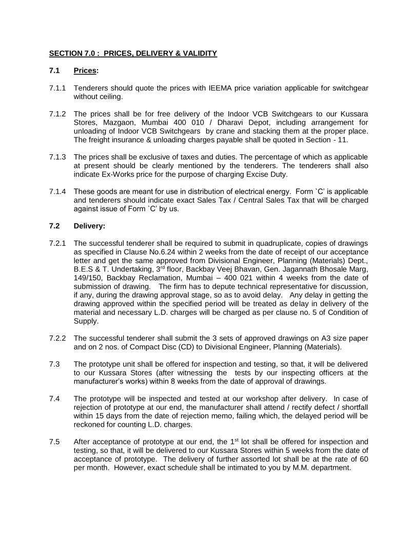
SECTION 7.0 : PRICES, DELIVERY & VALIDITY 7.1 Prices:
7.1.1 Tenderers should quote the prices with IEEMA price variation applicable for switchgear
without ceiling. 7.1.2 The prices shall be for free delivery of the Indoor VCB Switchgears to our Kussara
Stores, Mazgaon, Mumbai 400 010 / Dharavi Depot, including arrangement for unloading of Indoor VCB Switchgears by crane and stacking them at the proper place. The freight insurance & unloading charges payable shall be quoted in Section - 11.
7.1.3 The prices shall be exclusive of taxes and duties. The percentage of which as applicable
at present should be clearly mentioned by the tenderers. The tenderers shall also indicate Ex-Works price for the purpose of charging Excise Duty.
7.1.4 These goods are meant for use in distribution of electrical energy. Form `C’ is applicable
and tenderers should indicate exact Sales Tax / Central Sales Tax that will be charged against issue of Form `C’ by us.
7.2 Delivery: 7.2.1 The successful tenderer shall be required to submit in quadruplicate, copies of drawings
as specified in Clause No.6.24 within 2 weeks from the date of receipt of our acceptance letter and get the same approved from Divisional Engineer, Planning (Materials) Dept., B.E.S & T. Undertaking, 3rd floor, Backbay Veej Bhavan, Gen. Jagannath Bhosale Marg, 149/150, Backbay Reclamation, Mumbai – 400 021 within 4 weeks from the date of submission of drawing. The firm has to depute technical representative for discussion, if any, during the drawing approval stage, so as to avoid delay. Any delay in getting the drawing approved within the specified period will be treated as delay in delivery of the material and necessary L.D. charges will be charged as per clause no. 5 of Condition of Supply.
7.2.2 The successful tenderer shall submit the 3 sets of approved drawings on A3 size paper
and on 2 nos. of Compact Disc (CD) to Divisional Engineer, Planning (Materials). 7.3 The prototype unit shall be offered for inspection and testing, so that, it will be delivered
to our Kussara Stores (after witnessing the tests by our inspecting officers at the manufacturer’s works) within 8 weeks from the date of approval of drawings.
7.4 The prototype will be inspected and tested at our workshop after delivery. In case of
rejection of prototype at our end, the manufacturer shall attend / rectify defect / shortfall within 15 days from the date of rejection memo, failing which, the delayed period will be reckoned for counting L.D. charges.
7.5 After acceptance of prototype at our end, the 1st lot shall be offered for inspection and
testing, so that, it will be delivered to our Kussara Stores within 5 weeks from the date of acceptance of prototype. The delivery of further assorted lot shall be at the rate of 60 per month. However, exact schedule shall be intimated to you by M.M. department.
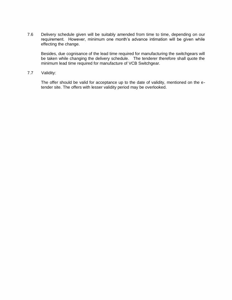
7.6 Delivery schedule given will be suitably amended from time to time, depending on our
requirement. However, minimum one month’s advance intimation will be given while effecting the change.
Besides, due cognisance of the lead time required for manufacturing the switchgears will be taken while changing the delivery schedule. The tenderer therefore shall quote the minimum lead time required for manufacture of VCB Switchgear.
7.7 Validity:
The offer should be valid for acceptance up to the date of validity, mentioned on the e-tender site. The offers with lesser validity period may be overlooked.
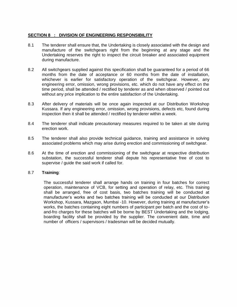
SECTION 8 : DIVISION OF ENGINEERING RESPONSIBILITY
8.1 The tenderer shall ensure that, the Undertaking is closely associated with the design and
manufacture of the switchgears right from the beginning at any stage and the Undertaking reserves the right to inspect the circuit breaker and associated equipment during manufacture.
8.2 All switchgears supplied against this specification shall be guaranteed for a period of 66
months from the date of acceptance or 60 months from the date of installation, whichever is earlier for satisfactory operation of the switchgear. However, any engineering error, omission, wrong provisions, etc. which do not have any effect on the time period, shall be attended / rectified by tenderer as and when observed / pointed out without any price implication to the entire satisfaction of the Undertaking.
8.3 After delivery of materials will be once again inspected at our Distribution Workshop
Kussara. If any engineering error, omission, wrong provisions, defects etc, found during inspection then it shall be attended / rectified by tenderer within a week.
8.4 The tenderer shall indicate precautionary measures required to be taken at site during
erection work. 8.5 The tenderer shall also provide technical guidance, training and assistance in solving
associated problems which may arise during erection and commissioning of switchgear. 8.6 At the time of erection and commissioning of the switchgear at respective distribution
substation, the successful tenderer shall depute his representative free of cost to supervise / guide the said work if called for.
8.7 Training:
The successful tenderer shall arrange hands on training in four batches for correct
operation, maintenance of VCB, for setting and operation of relay, etc. This training shall be arranged, free of cost basis, two batches training will be conducted at manufacturer’s works and two batches training will be conducted at our Distribution Workshop, Kussara, Mazgaon, Mumbai -10. However, during training at manufacturer’s works, the batches containing eight numbers of participant per batch and the cost of to-and-fro charges for these batches will be borne by BEST Undertaking and the lodging, boarding facility shall be provided by the supplier. The convenient date, time and number of officers / supervisors / tradesman will be decided mutually.
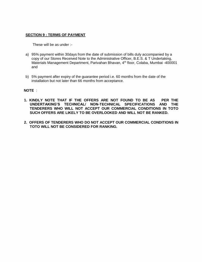
SECTION 9 : TERMS OF PAYMENT
These will be as under :-
a) 95% payment within 30days from the date of submission of bills duly accompanied by a copy of our Stores Received Note to the Administrative Officer, B.E.S. & T Undertaking, Materials Management Department, Parivahan Bhavan, 4th floor, Colaba, Mumbai -400001 and
b) 5% payment after expiry of the guarantee period i.e. 60 months from the date of the installation but not later than 66 months from acceptance.
NOTE :
1. KINDLY NOTE THAT IF THE OFFERS ARE NOT FOUND TO BE AS PER THE UNDERTAKING’S TECHNICAL/ NON-TECHNICAL SPECIFICATIONS AND THE TENDERERS WHO WILL NOT ACCEPT OUR COMMERCIAL CONDITIONS IN TOTO SUCH OFFERS ARE LIKELY TO BE OVERLOOKED AND WILL NOT BE RANKED.
2. OFFERS OF TENDERERS WHO DO NOT ACCEPT OUR COMMERCIAL CONDITIONS IN TOTO WILL NOT BE CONSIDERED FOR RANKING.
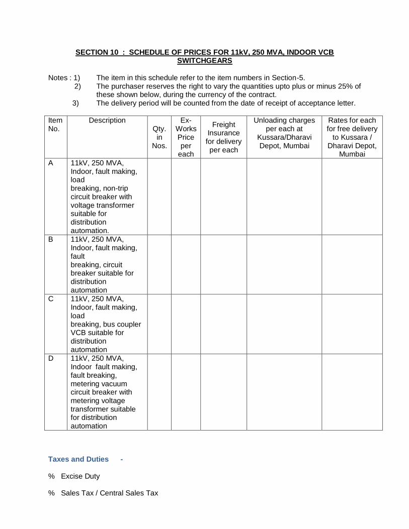
SECTION 10 : SCHEDULE OF PRICES FOR 11kV, 250 MVA, INDOOR VCB SWITCHGEARS
Notes : 1) The item in this schedule refer to the item numbers in Section-5. 2) The purchaser reserves the right to vary the quantities upto plus or minus 25% of
these shown below, during the currency of the contract. 3) The delivery period will be counted from the date of receipt of acceptance letter.
Item No.
Description Qty. in
Nos.
Ex-Works Price per
each
Freight Insurance for delivery per each
Unloading charges per each at
Kussara/Dharavi Depot, Mumbai
Rates for each for free delivery
to Kussara / Dharavi Depot,
Mumbai
A 11kV, 250 MVA, Indoor, fault making, load breaking, non-trip circuit breaker with voltage transformer suitable for distribution automation.
B 11kV, 250 MVA, Indoor, fault making, fault breaking, circuit breaker suitable for distribution automation
C 11kV, 250 MVA, Indoor, fault making, load breaking, bus coupler VCB suitable for distribution automation
D 11kV, 250 MVA, Indoor fault making, fault breaking, metering vacuum circuit breaker with metering voltage transformer suitable for distribution automation
Taxes and Duties - % Excise Duty % Sales Tax / Central Sales Tax
% Octroi Delivery Period WE HEREBY AGREE TO ACCEPT THE ORDER AT THE ABOVE RATES.
SIGNATURE OF TENDERER _______________
DATE : ___________________

SECTION: 11 Technical Particulars (Data by purchaser)
1.0 SWITCHGEAR
1.1 Type Metal clad, air insulated with VCB type circuit breaker, vertically isolating and horizontally draw out type.
1.2 Service Indoor
1.3 Mounting Free standing, floor mounted
1.4 System Voltage 11 KV
1.5 Voltage variation +6%, -9%
1.6 Frequency 50 Hz +/- 3%
1.7 Phase 3
1.8 Rated voltage 12 KV
1.9 Rated current 630 Amps
1.10 Short circuit current rating for 3 sec.
13.2 kA
1.11 Insulation level
(PF rms / Impulse peak)
28 kV / 75 kV
1.12 System ground Effectively earthed
1.13 Enclosure degree of protection
IP – 5X
1.14 Bus bar - Main 630 Amps, Short time rating as per 1.10
i) Material copper
ii) Bus bar sleeve Covered with insulating sleeves
iii) Bus identification Colour coded
1.15 Auxiliary bus bar Copper
1.16 Auxiliary DC Supply 24 V DC
1.17 Hardware Stainless steel.
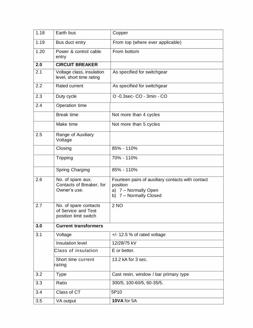
1.18 Earth bus Copper
1.19 Bus duct entry From top (where ever applicable)
1.20 Power & control cable entry
From bottom
2.0 CIRCUIT BREAKER
2.1 Voltage class, insulation level, short time rating
As specified for switchgear
2.2 Rated current As specified for switchgear
2.3 Duty cycle O -0.3sec- CO - 3min - CO
2.4 Operation time
Break time Not more than 4 cycles
Make time Not more than 5 cycles
2.5 Range of Auxiliary Voltage
Closing 85% - 110%
Tripping 70% - 110%
Spring Charging 85% - 110%
2.6 No. of spare aux. Contacts of Breaker, for Owner’s use.
Fourteen pairs of auxiliary contacts with contact position
a) 7 – Normally Open b) 7 – Normally Closed
2.7 No. of spare contacts
of Service and Test position limit switch
2 NO
3.0 Current transformers
3.1 Voltage +/- 12.5 % of rated voltage
Insulation level 12/28/75 kV
Class of insulat ion E or better.
Short time current rating
13.2 kA for 3 sec.
3.2 Type Cast resin, window / bar primary type
3.3 Ratio 300/5, 100-60/5, 60-35/5.
3.4 Class of CT 5P10
3.5 VA output 10VA for 5A
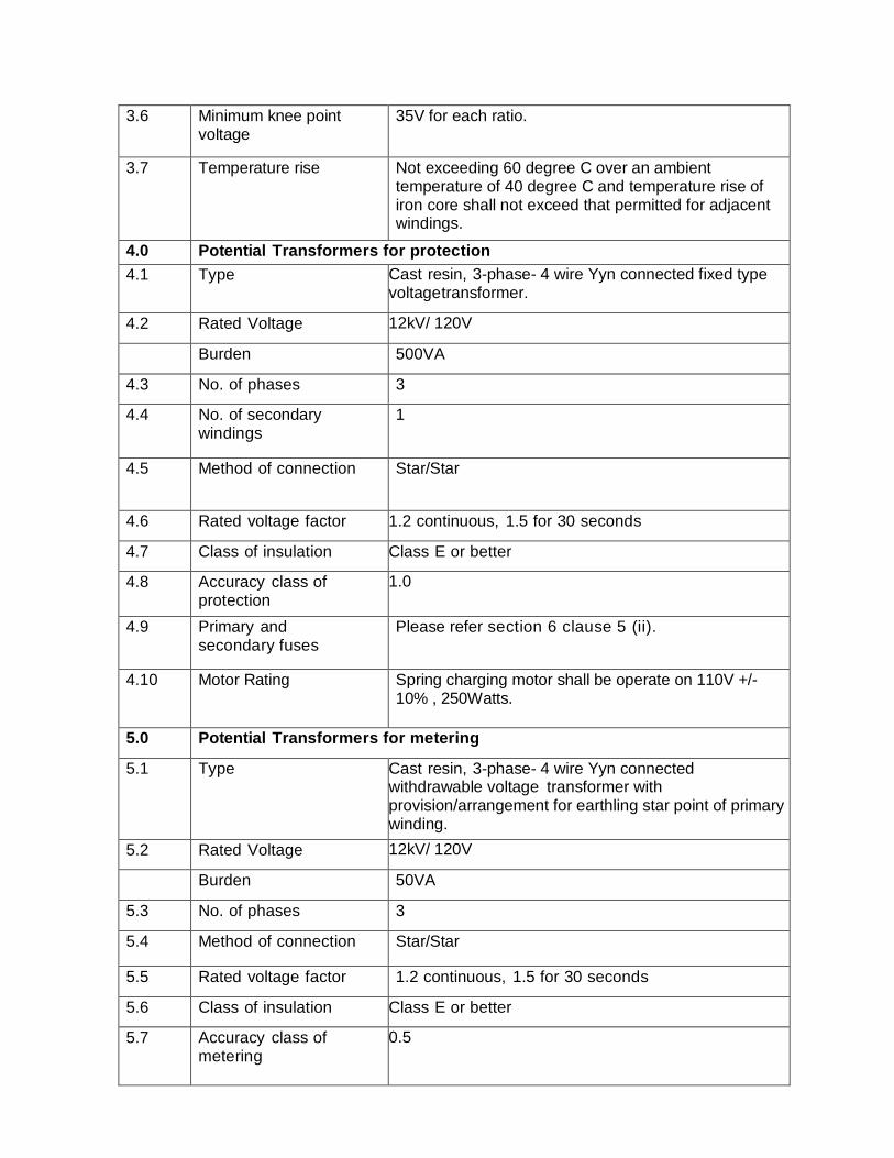
3.6 Minimum knee point voltage
35V for each ratio.
3.7 Temperature rise Not exceeding 60 degree C over an ambient temperature of 40 degree C and temperature rise of iron core shall not exceed that permitted for adjacent windings.
4.0 Potential Transformers for protection
4.1 Type Cast resin, 3-phase- 4 wire Yyn connected fixed type voltage transformer.
4.2 Rated Voltage 12kV/ 120V
Burden 500VA
4.3 No. of phases 3
4.4 No. of secondary windings
1
4.5 Method of connection Star/Star
4.6 Rated voltage factor 1.2 continuous, 1.5 for 30 seconds
4.7 Class of insulation Class E or better
4.8 Accuracy class of protection
1.0
4.9 Primary and secondary fuses
Please refer section 6 clause 5 (ii).
4.10 Motor Rating Spring charging motor shall be operate on 110V +/- 10% , 250Watts.
5.0 Potential Transformers for metering
5.1 Type Cast resin, 3-phase- 4 wire Yyn connected withdrawable voltage transformer with provision/arrangement for earthling star point of primary winding.
5.2 Rated Voltage 12kV/ 120V
Burden 50VA
5.3 No. of phases 3
5.4 Method of connection Star/Star
5.5 Rated voltage factor 1.2 continuous, 1.5 for 30 seconds
5.6 Class of insulation Class E or better
5.7 Accuracy class of metering
0.5
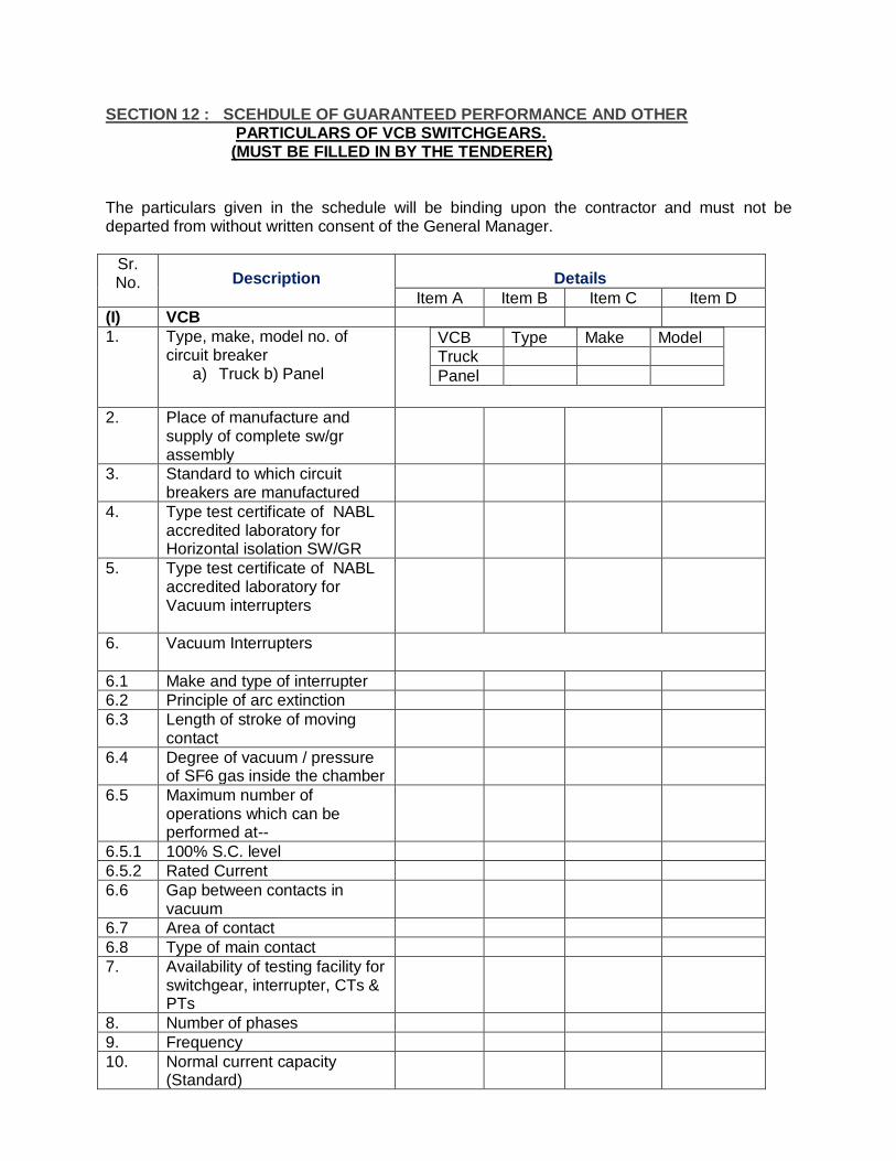
SECTION 12 : SCEHDULE OF GUARANTEED PERFORMANCE AND OTHER PARTICULARS OF VCB SWITCHGEARS. (MUST BE FILLED IN BY THE TENDERER)
The particulars given in the schedule will be binding upon the contractor and must not be departed from without written consent of the General Manager.
Sr. No. Description Details
Item A Item B Item C Item D
(I) VCB
1. Type, make, model no. of circuit breaker
a) Truck b) Panel
VCB Type Make Model
Truck
Panel
2. Place of manufacture and supply of complete sw/gr assembly
3. Standard to which circuit breakers are manufactured
4. Type test certificate of NABL accredited laboratory for Horizontal isolation SW/GR
5. Type test certificate of NABL accredited laboratory for Vacuum interrupters
6. Vacuum Interrupters
6.1 Make and type of interrupter
6.2 Principle of arc extinction
6.3 Length of stroke of moving contact
6.4 Degree of vacuum / pressure of SF6 gas inside the chamber
6.5 Maximum number of operations which can be performed at--
6.5.1 100% S.C. level
6.5.2 Rated Current
6.6 Gap between contacts in vacuum
6.7 Area of contact
6.8 Type of main contact
7. Availability of testing facility for switchgear, interrupter, CTs & PTs
8. Number of phases
9. Frequency
10. Normal current capacity (Standard)
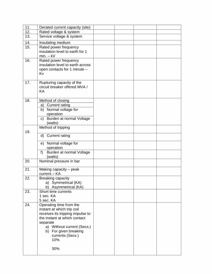
11. Derated current capacity (site)
12. Rated voltage & system
13. Service voltage & system
14. Insulating medium
15. Rated power frequency insulation level to earth for 1 min. – kV
16. Rated power frequency insulation level to earth across open contacts for 1 minute – Kv
17. Rupturing capacity of the circuit breaker offered MVA / KA
18. Method of closing
a) Current rating
b) Normal voltage for operation
c) Burden at normal Voltage (watts)
19.
Method of tripping
d) Current rating
e) Normal voltage for operation
f) Burden at normal Voltage (watts)
20. Nominal pressure in bar
21. Making capacity – peak current – KA
22. Breaking capacity a) Symmetrical (KA) b) Asymmetrical (KA)
23. Short time currents 1 sec. KA 5 sec. KA
24. Operating time from the instant at which trip coil receives its tripping impulse to the instant at which contact separate
a) Without current (Secs.) b) For given breaking
currents (Secs.) 10% 30%

60% 100%
Short circuit
25. Arc duration from separation of arcing contacts to instant of arc extinction stated for breaking currents of no. of loops at 10% of short circuit 30% -- do – 60% -- do – 100% -- do –
26. Make time
27. No. of current interrupting breakers in series per phase
28. Speed of break (100%) S.C. current
29. Length of stroke of moving contacts
30. Type of Main Contacts
31. High voltage test on complete assembled circuit breaker. a) 50 Hz Test voltage for 1
min.-kV b) Impulse test withstand
voltage on 1/50 kV full wave.
32. Minimum clearance in air for switchgear assembly
33. Surface protection & the metal enclosure
a) from inside b) from outside
34. Suitable cable entry in two parts for respective size of cables
35. a) Year when the first vacuum circuit breaker was put in commercial service.
b) No. of years the particular design of the circuit breaker has been in service
36. Overall Maximum dimensions of switchgears including all projections in mm. (Wx D x H)
37 Depth of the Truck (in mm. Max)
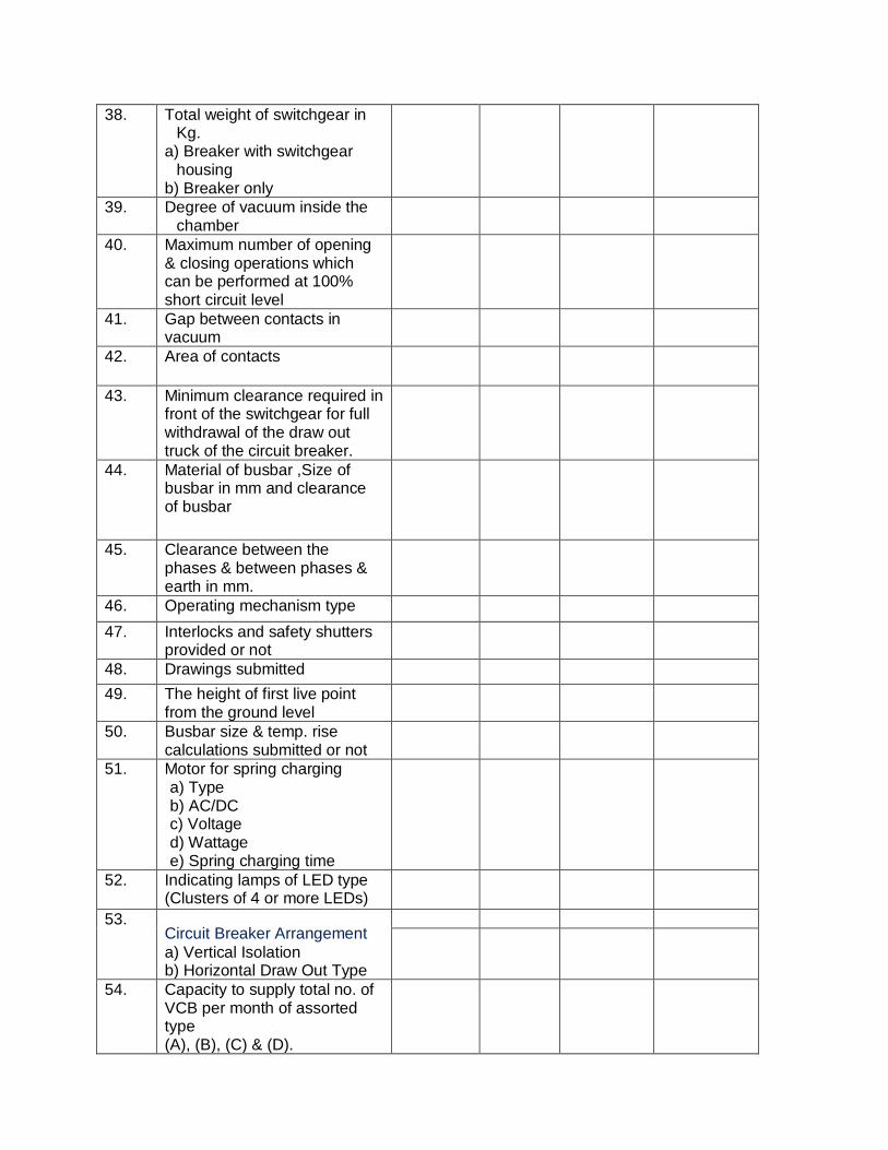
38. Total weight of switchgear in Kg.
a) Breaker with switchgear housing
b) Breaker only
39. Degree of vacuum inside the chamber
40. Maximum number of opening & closing operations which can be performed at 100% short circuit level
41. Gap between contacts in vacuum
42. Area of contacts
43. Minimum clearance required in front of the switchgear for full withdrawal of the draw out truck of the circuit breaker.
44. Material of busbar ,Size of busbar in mm and clearance of busbar
45. Clearance between the phases & between phases & earth in mm.
46. Operating mechanism type
47. Interlocks and safety shutters provided or not
48. Drawings submitted
49. The height of first live point from the ground level
50. Busbar size & temp. rise calculations submitted or not
51. Motor for spring charging a) Type b) AC/DC c) Voltage d) Wattage e) Spring charging time
52. Indicating lamps of LED type (Clusters of 4 or more LEDs)
53. Circuit Breaker Arrangement
a) Vertical Isolation b) Horizontal Draw Out Type
54. Capacity to supply total no. of VCB per month of assorted type (A), (B), (C) & (D).
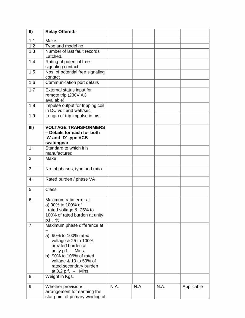
II) Relay Offered:-
1.1 Make
1.2 Type and model no.
1.3 Number of last fault records Latched.
1.4 Rating of potential free signaling contact
1.5 Nos. of potential free signaling contact
1.6 Communication port details
1.7 External status input for remote trip (230V AC available)
1.8 Impulse output for tripping coil in DC volt and watt/sec.
1.9 Length of trip impulse in ms.
III) VOLTAGE TRANSFORMERS – Details for each for both ‘A’ and ‘D’ type VCB switchgear
1. Standard to which it is manufactured
2 Make
3. No. of phases, type and ratio
4. Rated burden / phase VA
5. Class
6. Maximum ratio error at a) 90% to 100% of rated voltage & 25% to 100% of rated burden at unity p.f.. %
7. Maximum phase difference at -- a) 90% to 100% rated voltage & 25 to 100% or rated burden at unity p.f. - Mins. b) 90% to 106% of rated voltage & 10 to 50% of rated secondary burden at 0.2 p.f. -- Mins.
8. Weight in Kgs.
9. Whether provision/ arrangement for earthing the star point of primary winding of
N.A. N.A. N.A. Applicable
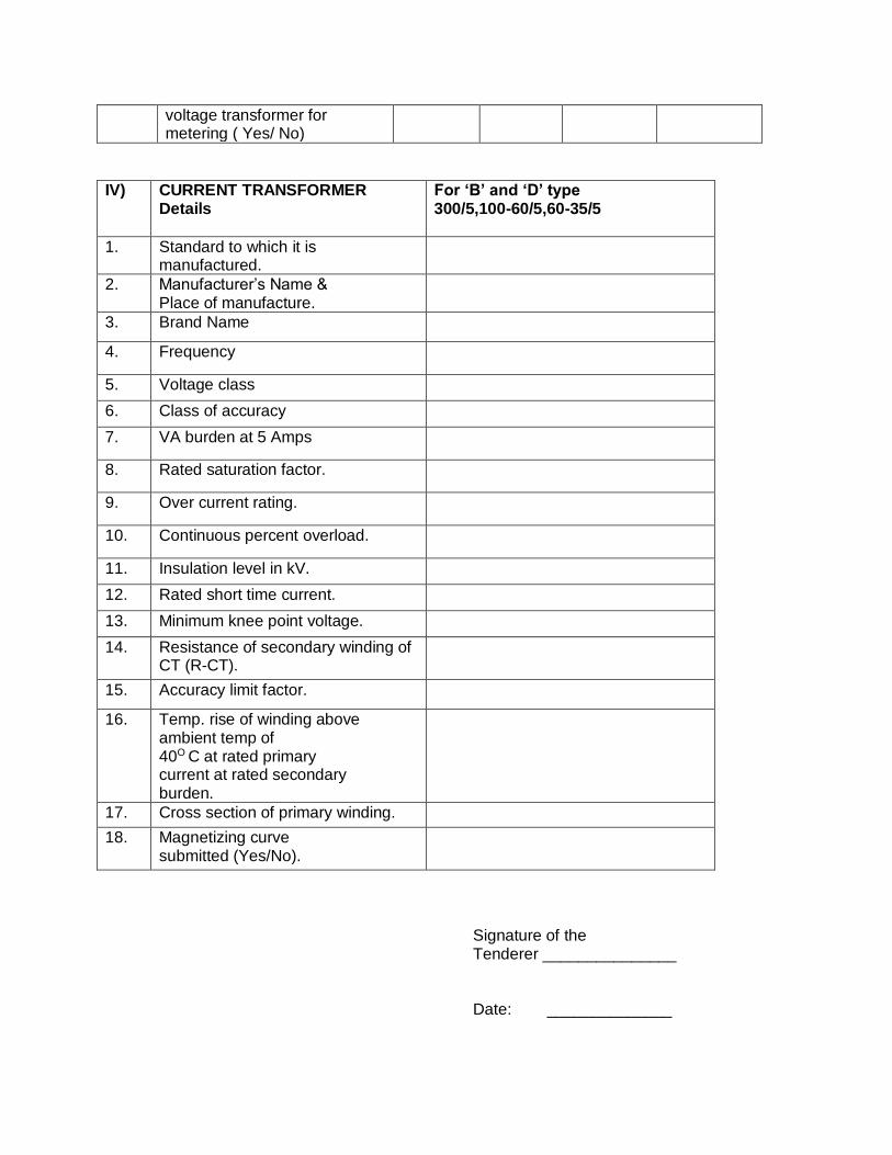
voltage transformer for metering ( Yes/ No)
IV) CURRENT TRANSFORMER Details
For ‘B’ and ‘D’ type 300/5,100-60/5,60-35/5
1. Standard to which it is manufactured.
2. Manufacturer’s Name & Place of manufacture.
3. Brand Name
4. Frequency
5. Voltage class
6. Class of accuracy
7. VA burden at 5 Amps
8. Rated saturation factor.
9. Over current rating.
10. Continuous percent overload.
11. Insulation level in kV.
12. Rated short time current.
13. Minimum knee point voltage.
14. Resistance of secondary winding of CT (R-CT).
15. Accuracy limit factor.
16. Temp. rise of winding above ambient temp of 40O C at rated primary current at rated secondary burden.
17. Cross section of primary winding.
18. Magnetizing curve submitted (Yes/No).
Signature of the Tenderer _______________ Date: ______________
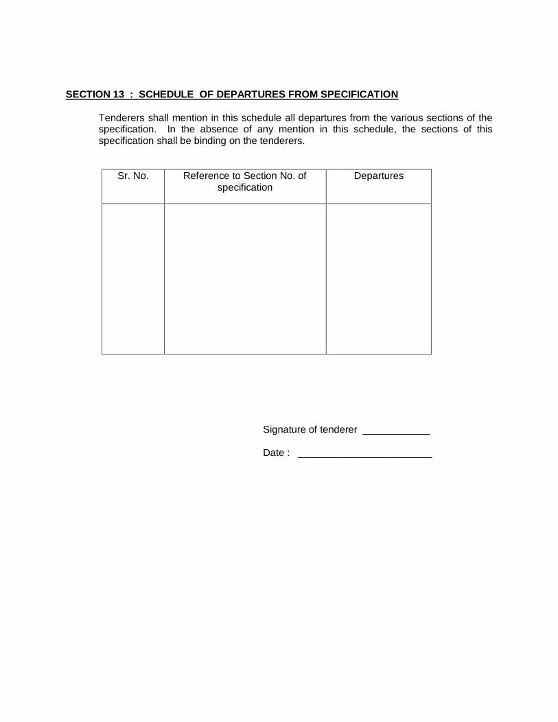
SECTION 13 : SCHEDULE OF DEPARTURES FROM SPECIFICATION
Tenderers shall mention in this schedule all departures from the various sections of the specification. In the absence of any mention in this schedule, the sections of this specification shall be binding on the tenderers.
Sr. No. Reference to Section No. of specification
Departures
Signature of tenderer ____________ Date : ________________________
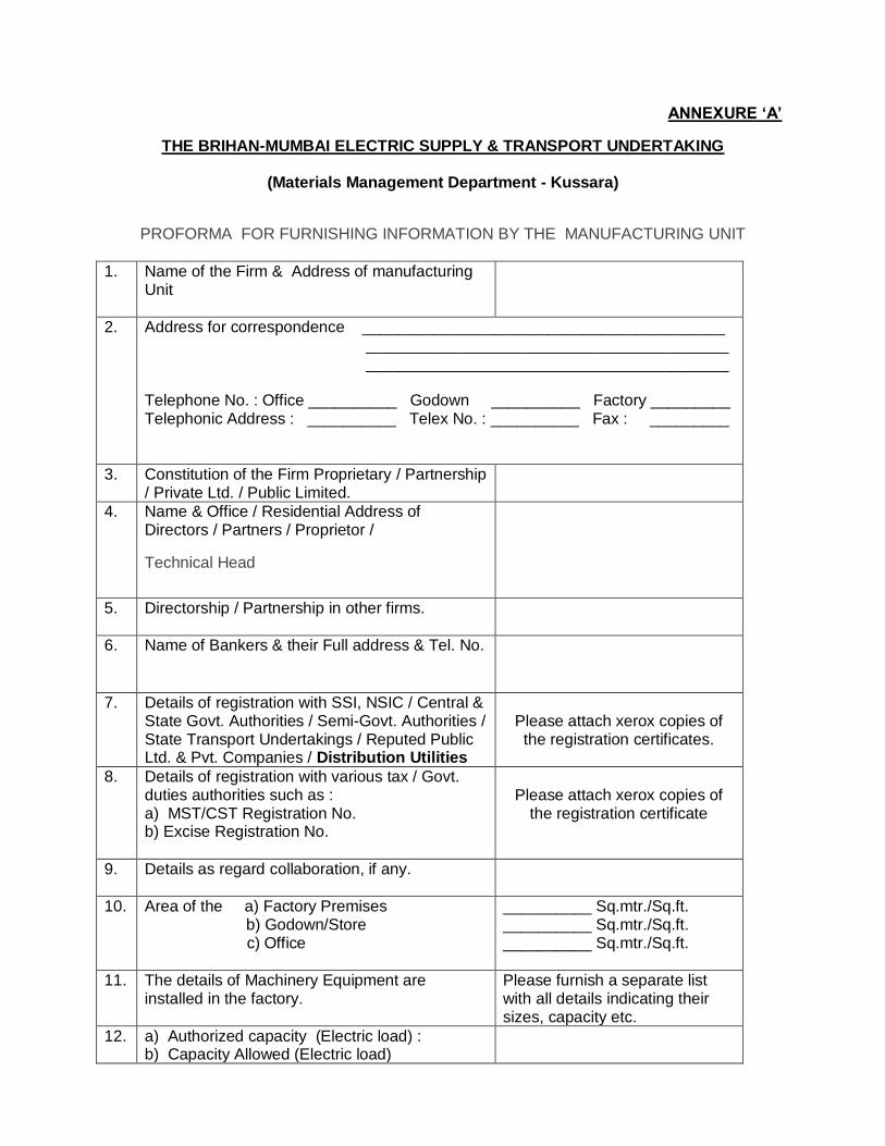
ANNEXURE ‘A’
THE BRIHAN-MUMBAI ELECTRIC SUPPLY & TRANSPORT UNDERTAKING
(Materials Management Department - Kussara)
PROFORMA FOR FURNISHING INFORMATION BY THE MANUFACTURING UNIT
1. Name of the Firm & Address of manufacturing Unit
2. Address for correspondence _________________________________________ _________________________________________ _________________________________________ Telephone No. : Office __________ Godown __________ Factory _________ Telephonic Address : __________ Telex No. : __________ Fax : _________
3. Constitution of the Firm Proprietary / Partnership / Private Ltd. / Public Limited.
4. Name & Office / Residential Address of Directors / Partners / Proprietor /
Technical Head
5. Directorship / Partnership in other firms.
6. Name of Bankers & their Full address & Tel. No.
7. Details of registration with SSI, NSIC / Central & State Govt. Authorities / Semi-Govt. Authorities / State Transport Undertakings / Reputed Public Ltd. & Pvt. Companies / Distribution Utilities
Please attach xerox copies of the registration certificates.
8. Details of registration with various tax / Govt. duties authorities such as : a) MST/CST Registration No. b) Excise Registration No.
Please attach xerox copies of
the registration certificate
9. Details as regard collaboration, if any.
10. Area of the a) Factory Premises b) Godown/Store c) Office
__________ Sq.mtr./Sq.ft. __________ Sq.mtr./Sq.ft. __________ Sq.mtr./Sq.ft.
11. The details of Machinery Equipment are installed in the factory.
Please furnish a separate list with all details indicating their sizes, capacity etc.
12. a) Authorized capacity (Electric load) : b) Capacity Allowed (Electric load)
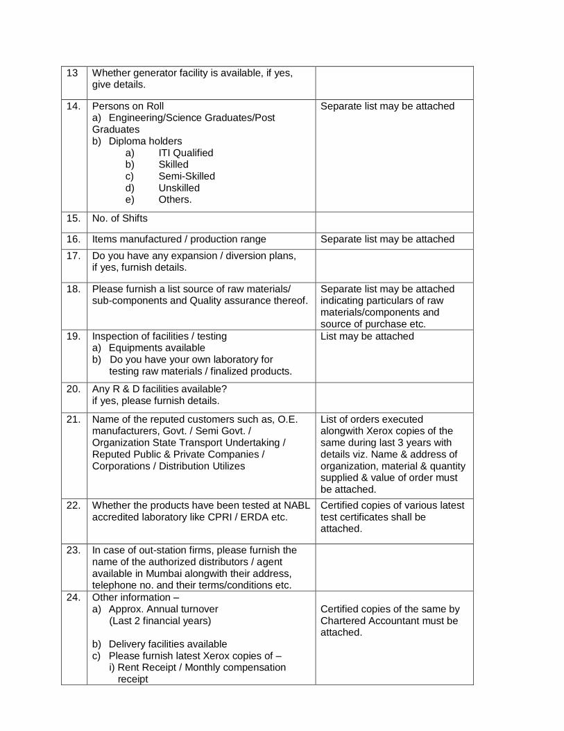
13 Whether generator facility is available, if yes, give details.
14. Persons on Roll a) Engineering/Science Graduates/Post Graduates b) Diploma holders
a) ITI Qualified b) Skilled c) Semi-Skilled d) Unskilled e) Others.
Separate list may be attached
15. No. of Shifts
16. Items manufactured / production range Separate list may be attached
17. Do you have any expansion / diversion plans, if yes, furnish details.
18. Please furnish a list source of raw materials/ sub-components and Quality assurance thereof.
Separate list may be attached indicating particulars of raw materials/components and source of purchase etc.
19. Inspection of facilities / testing a) Equipments available b) Do you have your own laboratory for testing raw materials / finalized products.
List may be attached
20. Any R & D facilities available? if yes, please furnish details.
21. Name of the reputed customers such as, O.E. manufacturers, Govt. / Semi Govt. / Organization State Transport Undertaking / Reputed Public & Private Companies / Corporations / Distribution Utilizes
List of orders executed alongwith Xerox copies of the same during last 3 years with details viz. Name & address of organization, material & quantity supplied & value of order must be attached.
22. Whether the products have been tested at NABL accredited laboratory like CPRI / ERDA etc.
Certified copies of various latest test certificates shall be attached.
23. In case of out-station firms, please furnish the name of the authorized distributors / agent available in Mumbai alongwith their address, telephone no. and their terms/conditions etc.
24. Other information – a) Approx. Annual turnover (Last 2 financial years) b) Delivery facilities available c) Please furnish latest Xerox copies of – i) Rent Receipt / Monthly compensation receipt
Certified copies of the same by Chartered Accountant must be attached.
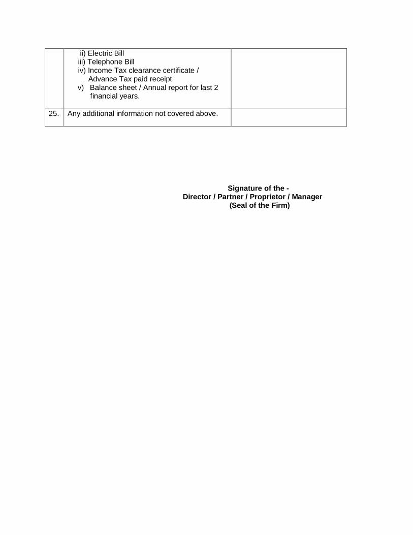
ii) Electric Bill iii) Telephone Bill iv) Income Tax clearance certificate / Advance Tax paid receipt
v) Balance sheet / Annual report for last 2 financial years.
25. Any additional information not covered above.
Signature of the - Director / Partner / Proprietor / Manager (Seal of the Firm)
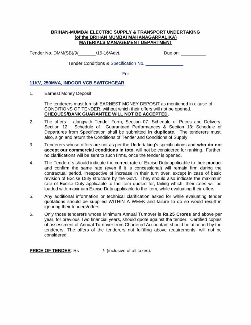
BRIHAN-MUMBAI ELECTRIC SUPPLY & TRANSPORT UNDERTAKING (of the BRIHAN MUMBAI MAHANAGARPALIKA)
MATERIALS MANAGEMENT DEPARTMENT
Tender No. DMM(SB)/9/_______/15-16/Advt. Due on: __________
Tender Conditions & Specification No. _______________
For
11KV, 250MVA, INDOOR VCB SWITCHGEAR
1. Earnest Money Deposit
The tenderers must furnish EARNEST MONEY DEPOSIT as mentioned in clause of CONDITIONS OF TENDER, without which their offers will not be opened. CHEQUES/BANK GUARANTEE WILL NOT BE ACCEPTED.
2. The offers alongwith Tender Form, Section 07: Schedule of Prices and Delivery, Section 12 : Schedule of Guaranteed Performances & Section 13: Schedule of Departures from Specification shall be submitted in duplicate. The tenderers must,
also, sign and return the Conditions of Tender and Conditions of Supply.
3. Tenderers whose offers are not as per the Undertaking's specifications and who do not accept our commercial conditions in toto, will not be considered for ranking. Further,
no clarifications will be sent to such firms, once the tender is opened.
4. The Tenderers should indicate the correct rate of Excise Duty applicable to their product and confirm the same rate (even if it is concessional) will remain firm during the contractual period, irrespective of increase in their turn over, except in case of basic revision of Excise Duty structure by the Govt. They should also indicate the maximum rate of Excise Duty applicable to the item quoted for, failing which, their rates will be loaded with maximum Excise Duty applicable to the item, while evaluating their offers.
5. Any additional information or technical clarification asked for while evaluating tender quotations should be supplied WITHIN A WEEK and failure to do so would result in ignoring their tenders/offers.
6. Only those tenderers whose Minimum Annual Turnover is Rs.25 Crores and above per year, for previous Two financial years, should quote against the tender. Certified copies of assessment of Annual Turnover from Chartered Accountant should be attached by the tenderers. The offers of the tenderers not fulfilling above requirements, will not be considered.
PRICE OF TENDER: Rs /- (inclusive of all taxes).
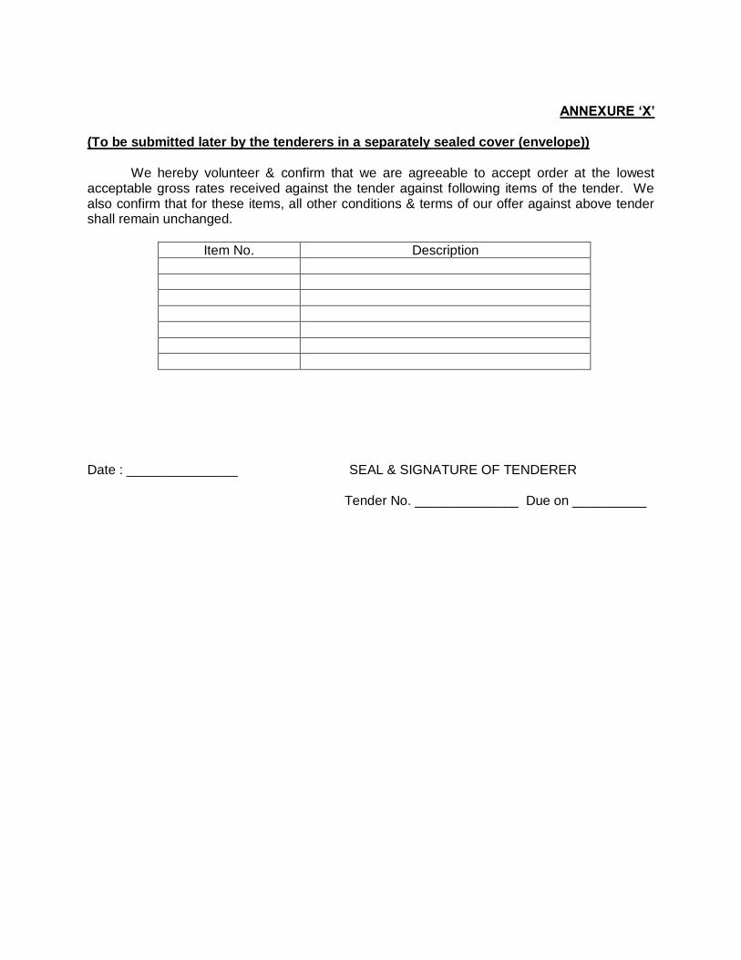
ANNEXURE ‘X’
(To be submitted later by the tenderers in a separately sealed cover (envelope))
We hereby volunteer & confirm that we are agreeable to accept order at the lowest acceptable gross rates received against the tender against following items of the tender. We also confirm that for these items, all other conditions & terms of our offer against above tender shall remain unchanged.
Item No. Description
Date : _______________ SEAL & SIGNATURE OF TENDERER Tender No. ______________ Due on __________
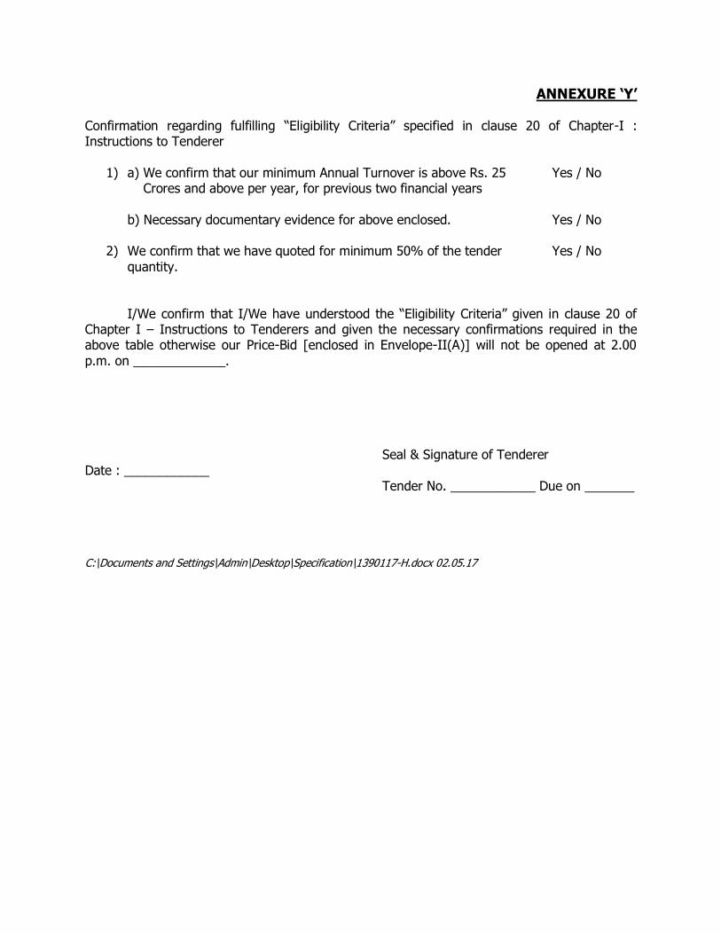
ANNEXURE ‘Y’
Confirmation regarding fulfilling “Eligibility Criteria” specified in clause 20 of Chapter-I : Instructions to Tenderer
1) a) We confirm that our minimum Annual Turnover is above Rs. 25 Yes / No Crores and above per year, for previous two financial years
b) Necessary documentary evidence for above enclosed. Yes / No
2) We confirm that we have quoted for minimum 50% of the tender Yes / No
quantity.
I/We confirm that I/We have understood the “Eligibility Criteria” given in clause 20 of Chapter I – Instructions to Tenderers and given the necessary confirmations required in the above table otherwise our Price-Bid [enclosed in Envelope-II(A)] will not be opened at 2.00
p.m. on _____________.
Seal & Signature of Tenderer
Date : ____________ Tender No. ____________ Due on _______
C:\Documents and Settings\Admin\Desktop\Specification\1390117-H.docx 02.05.17
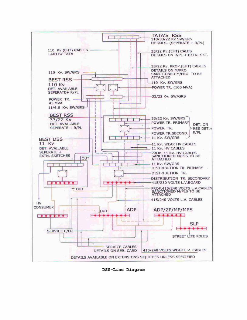
DSS-Line Diagram