the cansat book has been created for students
TRANSCRIPT


Version: September 2017 2
The CanSat book has been created for students participating in the Dutch CanSat Competition 2017-2018. It
is a guide to help them with the CanSat kit, enabling them to start from scratch and get a feeling of mastering
the kit as they read through the book. In the beginning, we will describe how they can get the Arduino board
up and running. Then we will address the missions. In this book we have described the primary mission and
how you can obtain data from it.
Together with the Dutch CanSat Competition 2017-2018 Guidelines, you now have all the information needed
to start your CanSat project!
Colofon
The CanSat Book has been written by Frank Hagenaars on behalf of ESERO NL. It is based on the work of
Thomas Gansmoe, Stian Vik Mathisen and Jøran Grande from NAROM, together with Jens F. Dalsgaard
Nielsen from Aalborg University and Nils Kristian Rossing from the Norwegian University of Science and
Technology published at: esero.no/wp-content/uploads/2015/11/The-CanSat-Book-R2.12.compressed.pdf
The CanSat kit used in this book has been developed by Fun met Electronica and based on the NAROM
CanSat Kit.
CanSat is an ESERO project being performed by NEMO on the instructions of the Netherlands Space Office
(NSO).
Photography cover: DigiDaan.

Version: September 2017 3
Introduction to CanSat ..................................................................................................................................... 5
What is a CanSat? ...................................................................................................................................... 5
The CanSat kit ............................................................................................................................................. 6
Contents of the kit ................................................................................................................................... 6
Arduino ............................................................................................................................................................ 8
Connecting the Arduino ............................................................................................................................... 9
Programming Arduino ............................................................................................................................... 10
1. Blink .............................................................................................................................................. 10
2. Let’s measure an analog voltage with Arduino: ............................................................................ 11
3. Measuring light intensity and temperature: ................................................................................... 13
4. Measuring barometric air pressure and temperature with BMP280 module: ................................ 14
Gathering data from serial port .................................................................................................................. 16
Assembly ....................................................................................................................................................... 17
Tools and requirements ............................................................................................................................. 17
The shield .................................................................................................................................................. 18
1. Solder the pin headers onto the BMP280 sensor ......................................................................... 18
2. Solder pin headers to the prototyping shield ................................................................................. 20
3. Solder the power switch to the shield ........................................................................................... 22
4. Make the female headers to attach APC220 and BMP280 to the shield ...................................... 23
5. Solder the female pinheader to the shield .................................................................................... 24
6. Solder the battery connector to the shield .................................................................................... 24
7. Powering Arduino .......................................................................................................................... 25
8. Connect the BMP280 to the shield ............................................................................................... 25
9. Connect the APC220 to the shield ................................................................................................ 26
10. Connect the shield to the Arduino board .................................................................................. 27
Testing Arduino/BMP280 .......................................................................................................................... 28
Set up the APC220 .................................................................................................................................... 29
Programming the transceivers with Arduino .......................................................................................... 29
Testing APC220 ........................................................................................................................................ 31
APC220 on CanSat: .............................................................................................................................. 31
APC220 on ground station: ................................................................................................................... 32
Gathering data at your ground station: .................................................................................................. 33
How to make an Arduino code for your missions: ..................................................................................... 33
Appendix ........................................................................................................................................................ 34
Altitude calculations ................................................................................................................................... 34
Antenna design ......................................................................................................................................... 36
Version: September 2017 4
Modulation ............................................................................................................................................. 36
APC220 ................................................................................................................................................. 36
Antennas ............................................................................................................................................... 36
CanSat Antenna .................................................................................................................................... 37
Ground station antenna ......................................................................................................................... 37
Parachute design ...................................................................................................................................... 38
Parachute production ............................................................................................................................ 38
Example assignments ........................................................................................................................... 38
Descent physics .................................................................................................................................... 38
Required descent parameters ............................................................................................................... 39
Semi-spherical parachute design .......................................................................................................... 40
Cross parachute design ........................................................................................................................ 40
Parapent ................................................................................................................................................ 40
Flat parachute design ............................................................................................................................ 41
Other recovery systems ........................................................................................................................ 41
CanSat Competition tips ............................................................................................................................ 43
Version: September 2017 5
Introduction to CanSat
What is a CanSat? A CanSat is a simulation of a real satellite, integrated within the volume and shape of a soft drinks can. The
challenge for students is to fit all the major subsystems found in a satellite, such as power, sensors and a
communication system, into this small volume. The CanSat is then launched to an altitude of one kilometre
by a rocket and its mission begins: to carry out a scientific experiment by measuring various characteristics
at different altitudes and achieving a safe landing. During the flight, the CanSat will use radio communication
to transmit data to a ground station.
CanSats offer a unique opportunity for a first practical experience of a real space project. The students will
be responsible for all aspects: designing the CanSat, selecting its sub-missions, integrating the components,
testing, preparing for launch and then analysing the data.
Version: September 2017 6
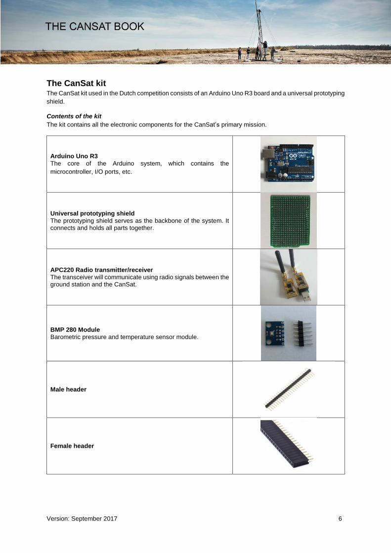
The CanSat kit The CanSat kit used in the Dutch competition consists of an Arduino Uno R3 board and a universal prototyping
shield.
Contents of the kit
The kit contains all the electronic components for the CanSat’s primary mission.
Arduino Uno R3 The core of the Arduino system, which contains the
microcontroller, I/O ports, etc.
Universal prototyping shield The prototyping shield serves as the backbone of the system. It connects and holds all parts together.
APC220 Radio transmitter/receiver The transceiver will communicate using radio signals between the ground station and the CanSat.
BMP 280 Module Barometric pressure and temperature sensor module.
Male header
Female header
Version: September 2017 7
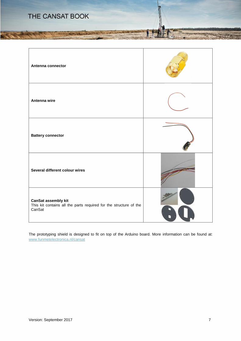
Antenna connector
Antenna wire
Battery connector
Several different colour wires
CanSat assembly kit This kit contains all the parts required for the structure of the CanSat
The prototyping shield is designed to fit on top of the Arduino board. More information can be found at:
www.funmetelectronica.nl/cansat

Version: September 2017 8
Arduino To carry out the primary mission during descent, CanSat has to measure barometric air pressure and
temperature. The sensors that will be used must be connected to an Arduino board. The Arduino board can
process the sensor signals. The data Arduino produces is sent by radio signals. Communication with a ground
station should be possible.
The core of the CanSat is the Arduino Uno R3.
Arduino is an open-source electronics platform based on easy-to-use hardware and software. Arduino boards
are able to read inputs from a sensor and turn them into an output. You can instruct your board on what to do
by sending a set of instructions to the microcontroller on the board.
To get started with Arduino, you can follow the next steps.
Let’s take a close look to the Arduino R3:
USB: USB connection can do two things. Firstly,
providing power to the Arduino from the
computer. Secondly, communicating with the
computer.
TX/RX: If uploading and communicating are not
effected through USB, pins D0 and D1 can be
used.
Power in: If the USB is not used as a power
supply, the power jack (5.5mm-2.1mm) or the
power pins Vin and GND can be used. Arduino
can manage power with a range of 5-20V.
Power out: Powering the external components
can be effected with the power pins 5V and
3.3V. The maximum current is 1A.
Analog in: Arduino can read analog voltage from 0V to 5V.
Digital in/out: These pins can be declared as input pins or output pins. As input pin, it can read input voltage:
<2.5V is LOW, >2.5V is HIGH. As output pin, LOW is 0V, HIGH is 5V. Pin 3, 5, 6, 9, 10 and 11 can provide a
PWM signal.
You can program the Arduino with Arduino IDE. You can download Arduino IDE at
www.arduino.cc/en/Main/Software

Version: September 2017 9
Connecting the Arduino Make sure you installed Arduino IDE properly. Open Arduino IDE and connect the Arduino UNO by USB. If
drivers are properly installed, the computer recognises the Arduino board.
Go to ‘Hulpmiddelen’ and connect the COM-port of the Arduino board by clicking.
In this example, it is COM3.

Version: September 2017 10
Programming Arduino The first sketch in Arduino is ‘Blink’.
You can find ‘Blink’ on ‘Bestand > Voorbeelden > Basic > Blink’.
Read the text from this sketch.
1. Blink
Turns on an LED for one second, then off for one second, repeatedly. Most Arduinos have an on-board LED
you can control. On the Uno, it is attached to digital pin 13.
// the setup function runs once when you press reset or power the board void setup() // initialize digital pin 13 as an output. pinMode(13, OUTPUT); // the loop function runs over and over again forever void loop() digitalWrite(13, HIGH); // turn the LED on (HIGH is the voltage level) delay(1000); // wait for a second digitalWrite(13, LOW); // turn the LED off by making the voltage LOW delay(1000); // wait for a second
When pressing Upload, you can see the upload progress at the right bottom.
Try to speed up the blinking LED. Each time you make a change to the code, do not forget to upload the new
code. The new code overwrites the old code in the Arduino.
Version: September 2017 11
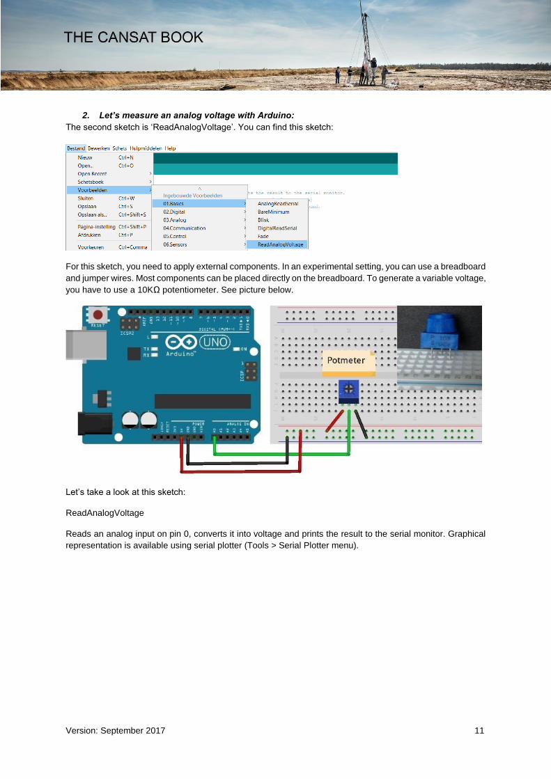
2. Let’s measure an analog voltage with Arduino:
The second sketch is ‘ReadAnalogVoltage’. You can find this sketch:
For this sketch, you need to apply external components. In an experimental setting, you can use a breadboard
and jumper wires. Most components can be placed directly on the breadboard. To generate a variable voltage,
you have to use a 10KΩ potentiometer. See picture below.
Let’s take a look at this sketch:
ReadAnalogVoltage
Reads an analog input on pin 0, converts it into voltage and prints the result to the serial monitor. Graphical
representation is available using serial plotter (Tools > Serial Plotter menu).

Version: September 2017 12
Attach the centre pin of a potentiometer to pin A0 and the outside pins to +5V and ground.
// the setup routine runs once when you press reset: void setup() // initialize serial communication at 9600 bits per second: Serial.begin(9600); // the loop routine runs over and over again forever: void loop() // read the input on analog pin 0: int sensorValue = analogRead(A0); // Convert the analog reading (which goes from 0 - 1023) to a voltage (0 - 5V): float voltage = sensorValue * (5.0 / 1023.0); // print out the value you read: Serial.println(voltage);
Do not forget to turn on the serial monitor (button on the top-right).
When you are running this sketch on the Arduino, you can read the voltage on the serial monitor. Try to
change the speed of measuring the values on A0. Create a delay of 1000 milliseconds.
You can see the values in the serial monitor.
Using the potentiometer, you can make any voltage on the centre pin between 0 – 5V. The main resistor of
10KΩ is cut into two pieces, the ratio of these two pieces can be adjusted by turning the potentiometer. In this
way, you can provide a voltage between 0 – 5 V on the centre pin.
Learn more about a voltage divider at: https://en.wikipedia.org/wiki/Voltage_divider
We can do more with this knowledge.

Version: September 2017 13
3. Measuring light intensity and temperature:
If we use one fixed resistor and one variable resistor, we can make a variable voltage. With a LDR (light
depending resistor) we can measure light intensity and with a NTC or PTC we can measure temperature.
Keep the same code (ReadAnalogVoltage), make a new circuit with the LDR and NTC.
Measure light intensity and temperature. Try to change the code to adapt the values in the serial monitor.

Version: September 2017 14
4. Measuring barometric air pressure and temperature with BMP280 module:
In the primary mission, you have to measure barometric air pressure and temperature. The CanSat kit
contains a module, the BMP280. This module can measure pressure and temperature. If you want to use it
with the Arduino IDE, you will need a library. The Arduino IDE can be extended through the use of libraries
to provide extra functionality to your sketches. Most libraries come with example sketches. You can find the
library in the CanSat download files. Copy the folder “Adafruit_BMP280” into the “libraries” folder in “Arduino”
– “My Documents”, Exit and restart Arduino IDE.
You can now find the example sketch bmp280test:
Wire the BMP280 module:
1. VCC 5V
2. GND GND
3. SCK/SCL D13
4. SDA/SDI D11
5. CSB D10
6. SDO D12

Version: September 2017 15
In the sketch, you have to ‘double forward slash’ and ‘unslash’ some lines.
#define BMP_CS 10 Adafruit_BMP280 bmp; // I2C //Adafruit_BMP280 bmp(BMP_CS); // hardware SPI //Adafruit_BMP280 bmp(BMP_CS, BMP_MOSI, BMP_MISO, BMP_SCK); void setup()
To:
#define BMP_CS 10 //Adafruit_BMP280 bmp; // I2C //Adafruit_BMP280 bmp(BMP_CS); // hardware SPI Adafruit_BMP280 bmp(BMP_CS, BMP_MOSI, BMP_MISO, BMP_SCK); void setup()
Now you can upload the sketch and open the serial port.

Version: September 2017 16
Gathering data from serial port If you want to use the data from the serial port, you can gather the data by using “Serial Debug Assistant”.
You can find this free software in the Windows Store.
You can save the data received to a text file. The text file can be imported in Excel or other spreadsheet
software. If you want to use the data in an easy way, you can change the code in the sketch first.
Note: If you want to use “Serial Debug Assistant”, you have to close the serial monitor on the Arduino IDE,
because only one program can listen to a Serial port at one time.

Version: September 2017 17
Assembly By following these guidelines, you can assemble the prototyping shield. This shield keeps the main
components together. For the primary mission you will need:
1. External power
2. Power switch
3. Radio transmitter
4. Temperature sensor
5. Pressure sensor
Tools and requirements The tools required to assemble are those required for soldering hobby electronics. We recommend that you
have the following equipment with you during the assembly
process:
Pliers
Soldering iron and solder. It is important that the solder
contains a flux core (this will facilitate the soldering).
Optional but recommended: flux remover (to clean flux
residue).
Optional: a third hand, which is very convenient if you are alone
while doing the assembly.
Optional: a solder wick remover in case you make a mistake
and want to unsolder the components.
Optional: extra flux (e.g. in a pen dispenser). This element is
optional but can help soldering the voltage regulator, which is surface mounted.
Note: The assembly requires basic soldering skills. However, you are working with quite delicate electronics.
If you do not have much experience with soldering microelectronics, you should practice first before you start
soldering the CanSat components to the prototyping shield. Consult these suggested tutorials to familiarise
yourself with soldering if needed:
Short but very informative soldering tutorial: www.youtube.com/watch?v=f95i88OSWB4
Extended soldering tutorial:
Part 1 - Tools: www.youtube.com/watch?v=J5Sb21qbpEQ&feature=youtu.be
Part 2 - Basic techniques: www.youtube.com/watch?v=fYz5nIHH0iY&feature=youtu.be
Part 3 - Surface Mount: www.youtube.com/watch?v=b9FC9fAlfQE&feature=youtu.be
Third hand

Version: September 2017 18
The shield The final product we will be working towards will look like this:
The shield is mounted on top of the Arduino UNO board. The battery holder, power switch, the transceiver
(APC220) and the pressure/temperature sensor (BMP280) are mounted on top of the shield.
1. Solder the pin headers onto the BMP280 sensor
We will be soldering the headers to the BMP280 sensor. Use the male pin headers included in the plastic
bag. Place the shorter ends of the headers through the holes.

Version: September 2017 19
Place the pinheaders and the BMP280 on a breadboard.
Preheat the two components briefly
Add a small amount of solder
Done!

Version: September 2017 20
2. Solder pin headers to the prototyping shield
Now that you have some practice in soldering headers, solder the headers of the prototyping shield. Use the
male headers. These have to be cut apart in 4 blocks; 1 x 6 pins, 2 x 8 pins and 1 x 10 pins.
The long part of the pins needs to be placed through the Arduino UNO board.
Place the shield on top of it. Note that the text printed on the shield is on top. Adjust the top of the pins so that
they are aligned with the top of the shield.
Version: September 2017 21
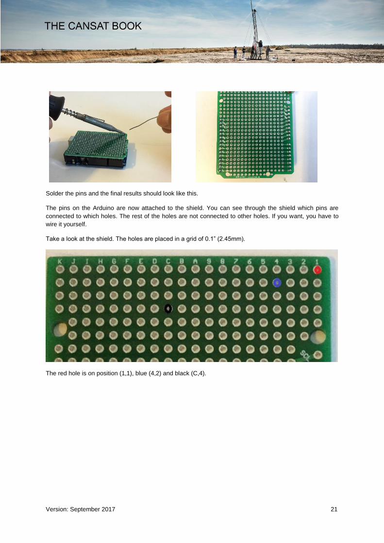
Solder the pins and the final results should look like this.
The pins on the Arduino are now attached to the shield. You can see through the shield which pins are
connected to which holes. The rest of the holes are not connected to other holes. If you want, you have to
wire it yourself.
Take a look at the shield. The holes are placed in a grid of 0.1” (2.45mm).
The red hole is on position (1,1), blue (4,2) and black (C,4).

Version: September 2017 22
3. Solder the power switch to the shield
The next step is the power switch.
You have to solder the power switch on holes (1,.1), (1,2) and (1,3). First, you must bend the pins of the
switch. Then you can solder the switch on top of the shield.

Version: September 2017 23
4. Make the female headers to attach APC220 and BMP280 to the shield
To attach the transceiver APC 220 and the BMP280, you need to solder two female pinheaders: 1 x 6 pins
and 1 x 7 pins. First you have to cut/break the pinheaders. Before you can break the pinheaders, you have
to make a cut, so it breaks at the right place. Note that you lose one pin by breaking the header. You can
make the cut with a sharp knife. Cut the header on both sides before breaking. Clean the edge with the same
knife.

Version: September 2017 24
5. Solder the female pinheader to the shield
The positioning of the headers is very important and the layout of the shield is tight. The 7 pinheader is for
the APC220. Its position is from (2,6) to (8,6). The 6 pinheader is for the BMP280. Its position is from (3,5) to
(8,5). You can place the headers on top of the shield and solder it on the bottom side.
6. Solder the battery connector to the shield
The next component to be soldered to the board is the battery connector. This is also a tricky step since the
board hole is bigger than the battery connector metal conductor. Use a third hand (or ask somebody to help
you) so that you are able to place everything in the right position and solder. Be careful not to burn your
assistant with the soldering iron!
The red wire has to be positioned in (3,2). At the bottom side you have to connect the same wire with (2,2)!
The black wire is positioned in (2,5). At the bottom side you have to connect the same wire with (2,6)!
Version: September 2017 25
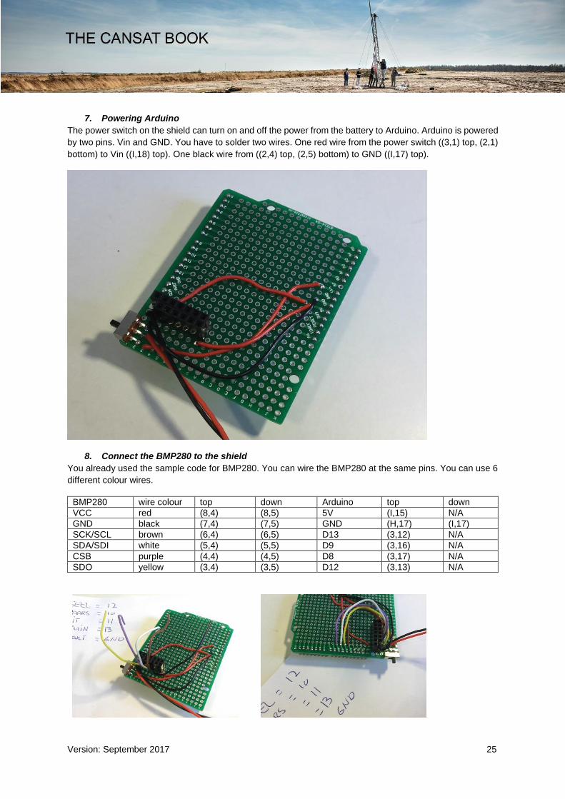
7. Powering Arduino
The power switch on the shield can turn on and off the power from the battery to Arduino. Arduino is powered
by two pins. Vin and GND. You have to solder two wires. One red wire from the power switch ((3,1) top, (2,1)
bottom) to Vin ((I,18) top). One black wire from ((2,4) top, (2,5) bottom) to GND ((I,17) top).
8. Connect the BMP280 to the shield
You already used the sample code for BMP280. You can wire the BMP280 at the same pins. You can use 6
different colour wires.
BMP280 wire colour top down Arduino top down
VCC red (8,4) (8,5) 5V (I,15) N/A
GND black (7,4) (7,5) GND (H,17) (I,17)
SCK/SCL brown (6,4) (6,5) D13 (3,12) N/A
SDA/SDI white (5,4) (5,5) D9 (3,16) N/A
CSB purple (4,4) (4,5) D8 (3,17) N/A
SDO yellow (3,4) (3,5) D12 (3,13) N/A
Version: September 2017 26
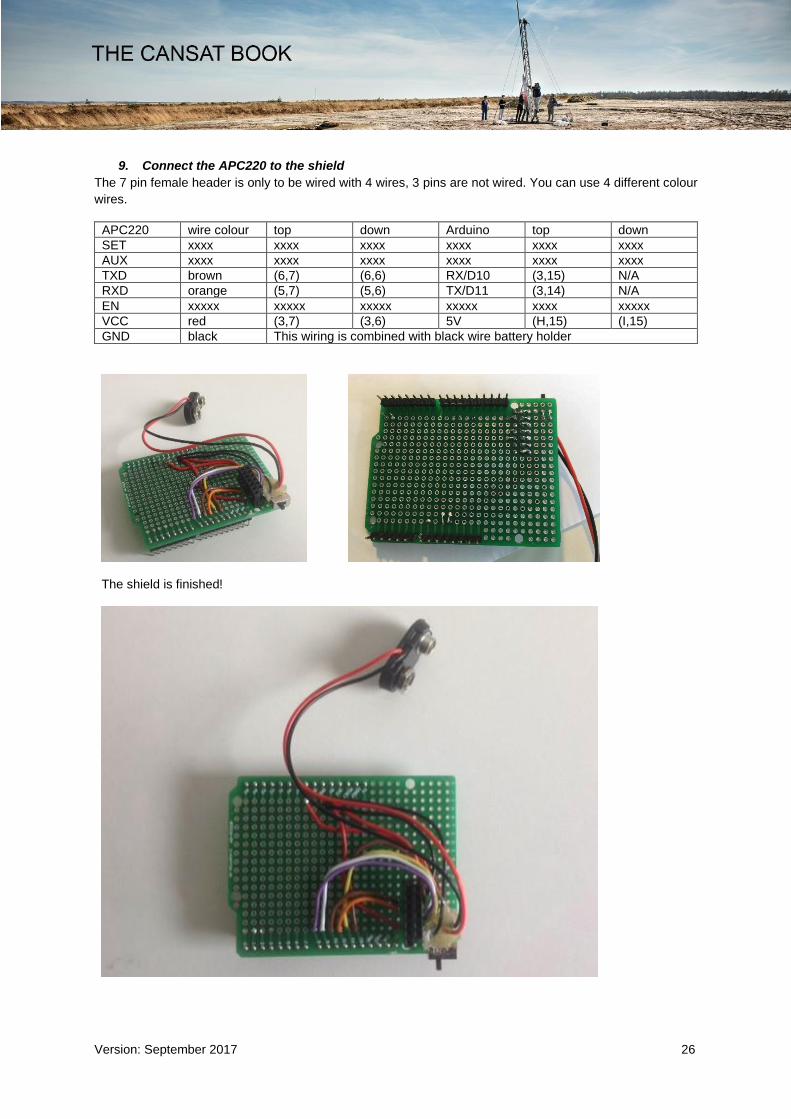
9. Connect the APC220 to the shield
The 7 pin female header is only to be wired with 4 wires, 3 pins are not wired. You can use 4 different colour
wires.
APC220 wire colour top down Arduino top down
SET xxxx xxxx xxxx xxxx xxxx xxxx
AUX xxxx xxxx xxxx xxxx xxxx xxxx
TXD brown (6,7) (6,6) RX/D10 (3,15) N/A
RXD orange (5,7) (5,6) TX/D11 (3,14) N/A
EN xxxxx xxxxx xxxxx xxxxx xxxx xxxxx
VCC red (3,7) (3,6) 5V (H,15) (I,15)
GND black This wiring is combined with black wire battery holder
The shield is finished!
Version: September 2017 27
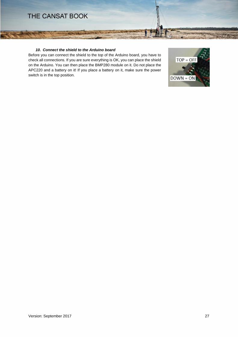
10. Connect the shield to the Arduino board
Before you can connect the shield to the top of the Arduino board, you have to
check all connections. If you are sure everything is OK, you can place the shield
on the Arduino. You can then place the BMP280 module on it. Do not place the
APC220 and a battery on it! If you place a battery on it, make sure the power
switch is in the top position.

Version: September 2017 28
Testing Arduino/BMP280
Open in Arduino IDE bmp280test:
First we make some changes to this sample file. We change the pin connections of D10 to D8 and D11 to
D9:
#include <Adafruit_Sensor.h> #include <Adafruit_BMP280.h> #define BMP_SCK 13 #define BMP_MISO 12 #define BMP_MOSI 11 #define BMP_CS 10 Adafruit_BMP280 bmp; // I2C
To:
#include <Adafruit_Sensor.h> #include <Adafruit_BMP280.h> #define BMP_SCK 13 #define BMP_MISO 12 #define BMP_MOSI 9 #define BMP_CS 8 Adafruit_BMP280 bmp; // I2C
In the sketch, you also have to ‘double forward slash’ and ‘unslash’ lines.
#define BMP_CS 10 Adafruit_BMP280 bmp; // I2C //Adafruit_BMP280 bmp(BMP_CS); // hardware SPI //Adafruit_BMP280 bmp(BMP_CS, BMP_MOSI, BMP_MISO, BMP_SCK); void setup()
To:
#define BMP_CS 10 //Adafruit_BMP280 bmp; // I2C //Adafruit_BMP280 bmp(BMP_CS); // hardware SPI Adafruit_BMP280 bmp(BMP_CS, BMP_MOSI, BMP_MISO, BMP_SCK); void setup()
With the APC220 disconnected and the power switch in the off position, you can upload the BMP280 sample
file to test a measurement in the serial monitor. If you close the serial monitor, you can also test the data in
‘Serial Debug Assistant’.

Version: September 2017 29
Set up the APC220 Telemetry is a technology that allows transmission of data
from remote measurement devices. Telemetry is an essential
part of satellite technology. Information is transmitted
wirelessly using radio waves. On the ground, these signals
are collected by radio receivers.
A transceiver is a device comprising both a transmitter and a
receiver that are combined in a single housing.
In the CanSat kit, we are using APC220, which is a
transceiver with a highly versatile low power radio solution
that is easy to set up and integrate into any project requiring
a wireless RF link.
You can connect one of these modules with your microcontroller. And you can connect your PC with another
APC220 module through a TTL/USB converter.
Programming the transceivers with Arduino
Set up the APC220: Connect the Arduino board to the computer and upload the program “apc220cfg.ino”.
Make sure you upload the program before you try to connect the transceiver to the Arduino board. Disconnect
the USB cable from the Arduino board and connect the transceiver to the Arduino as shown in the figure.
The transceiver will be connected to the pins labelled GND, 8,9,10,11,12 and 13 on the Arduino. Reconnect
the Arduino board through the USB cable and open the Serial Monitor. In the command line at the top, type
in ‘m’ and hit enter. This will bring up the menu shown in the figure.

Version: September 2017 30
If you type ‘r’ and hit enter, the program will return the current configuration for the transceiver. To reconfigure
the radio, type ‘w’ and the 5 parameters needed, with space between each parameter.
The first parameter is frequency, range 418000 – 455000.
For your CanSat, you will get your team frequency from the
CanSat organisation. The figure shows an example list of
frequencies.
The second parameter is RF data rate: 1/2/3/4 equals
2400/4800/9600/19200bps. The lower RF data rate
increases the transmission range.
The third parameter is Radio output power: 0 .. 9.
9 Equals 13dBm(20mW). 9 is max power.
The fourth parameter is UART baudrate: 0/1/2/3/4/5/6
equals 1200/2400/4800/9600/19200/38400/57600bps.
The baudrate should be set to 9600 bps.
The last parameter is Byte Chek Parity: 0/1/2 equals
NoCheck(8N1) / EvenParity(8E1) / OddParity(8O1).
Note that you have to configure both transceivers with the
same settings to be able to use them together.
Example entry: w 433100 3 9 3 0

Version: September 2017 31
Testing APC220 Finally, you can test the last electronic component of the CanSat kit: the APC220.
APC220 on CanSat:
Connect the shield to the Arduino and connect the
APC220 to the shield.
Open ‘APC220_test’ sketch. Let’s take a look at this sketch.
#include <SoftwareSerial.h> SoftwareSerial mySerial(10,11);//RX, TX int number = 0; void setup() Serial.begin(9600); mySerial.begin(9600); void loop() (number ++); Serial.print ("APC220 test "); Serial.println (number); mySerial.print ("APC220 test "); mySerial.println (number); delay (1000);
Using Software serial, we can make a virtual serial port on pins we can choose. It is now possible to upload
and check the serial monitor with the APC220 connected. Arduino communicates with pin 10 and 11 with
APC220. It is even possible to display in the serial monitor information other than wireless. The sketch
displays ‘APC220 test’ and an increasing number. This data is sent to the serial monitor by USB (Serial), the
same data is sent by APC220 (mySerial).
Upload the code and open the serial monitor and see that your text and numbers are displayed. Close the
serial monitor, disconnect the Arduino USB connection and power the Arduino by battery. With the power
switch in the ‘ON’ position, the sketch will run again on the Arduino and APC220 will be transmitting text and
numbers.
Version: September 2017 32
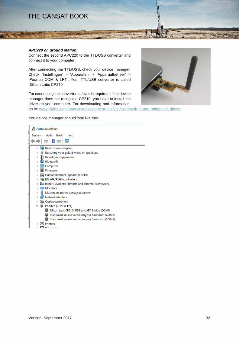
APC220 on ground station:
Connect the second APC220 to the TTL/USB converter and
connect it to your computer.
After connecting the TTL/USB, check your device manager.
Check ‘Instellingen’ > ‘Apparaten’ > ‘Apparaatbeheer’ >
‘Poorten COM & LPT’. Your TTL/USB converter is called
‘Silicon Labs CP210’.
For connecting the converter a driver is required. If the device
manager does not recognise CP210, you have to install the
driver on your computer. For downloading and information,
go to: www.silabs.com/products/development-tools/software/usb-to-uart-bridge-vcp-drivers
You device manager should look like this:

Version: September 2017 33
Gathering data at your ground station:
Open Serial Debug Assistant and select the right serial port.
Open serial port.
If your CanSat is transmitting and your second CP220 is connected, your ground station will receive data from
it. In this case increasing numbers. Note that Serial Debug Assistant can store data to a text file.
If you receive increasing numbers, the test will be successful!
How to make an Arduino code for your missions: You have completed the electronic components of the CanSat to carry out the primary mission. This handbook
does not provide the proper Arduino code for carrying out this mission. You have to make your own code by
combining pieces of code you used earlier. Try to decrease the transmitting data to a minimum and try to
prepare these data to import in Excel or other spreadsheet software. For instance: Use ‘comma’ or ‘space’
and ‘new line’ (println) in the data strings.
Finally: Note that several Arduino pins are not connected. If you add more missions, you can use these pins.
You can add the connections by soldering them to the shield.
Version: September 2017 34
Appendix
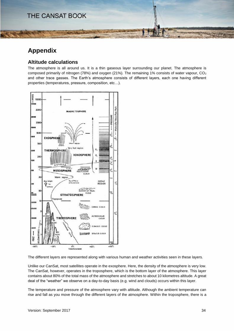
Altitude calculations The atmosphere is all around us. It is a thin gaseous layer surrounding our planet. The atmosphere is
composed primarily of nitrogen (78%) and oxygen (21%). The remaining 1% consists of water vapour, CO2
and other trace gasses. The Earth’s atmosphere consists of different layers, each one having different
properties (temperatures, pressure, composition, etc…).
The different layers are represented along with various human and weather activities seen in these layers.
Unlike our CanSat, most satellites operate in the exosphere. Here, the density of the atmosphere is very low.
The CanSat, however, operates in the troposphere, which is the bottom layer of the atmosphere. This layer
contains about 80% of the total mass of the atmosphere and stretches to about 10 kilometres altitude. A great
deal of the “weather” we observe on a day-to-day basis (e.g. wind and clouds) occurs within this layer.
The temperature and pressure of the atmosphere vary with altitude. Although the ambient temperature can
rise and fall as you move through the different layers of the atmosphere. Within the troposphere, there is a

Version: September 2017 35
linear relation between the temperature and altitude. On average, ascending one kilometre from sea level will
result in a temperature drop of 6.5 degrees Celsius.
The equation below provides the relation between temperature and altitude:
𝑇 = 𝑇1 + 𝑎(ℎ − ℎ1)
𝑇 Temperature in Kelvin
𝑇1 Starting temperature at ℎ1 altitude
ℎ Altitude in metres
ℎ1 Starting altitude
𝑎 Temperature gradient: -0.0065 K/m.
The relation between the pressure and the altitude is somewhat more complicated. The pressure not only
depends on the altitude but also on the temperature. Let’s start with the relation of pressure to temperature:
𝑝
𝑝1
= (𝑇
𝑇1
)−
𝑔0𝛼𝑅
𝑝 Pressure in Pascal
𝑝1 Start pressure in Pascal
𝑔0 Gravitational acceleration: 9.81𝑚
𝑠2
𝑅 Specific gas constant: 287.06 J/kg*K
Inserting this formula into the temperature-altitude relationship, we achieve the following expression for
altitude as a function of temperature and pressure:
ℎ =𝑇1
𝛼((
𝑝
𝑝1
)−
𝛼𝑅𝑔0
− 1) + ℎ1

Version: September 2017 36
Antenna design
Modulation
Radio communication involves sending information from one place to another, using electromagnetic waves,
also called radio waves. Electromagnetic waves are generated at an antenna when an alternating electric
current is connected to it. The antenna transforms the electric current in electromagnetic waves. At the
receiving end of the communication, the waves are transformed back into electric current by an antenna.
Using the radio waves to transfer information means that the
information needs to be added to the radio frequency used. Adding
this information is called modulation and can be obtained in
several ways. The most basic form is to transmit a (carrier)
frequency. This is called continuous wave (CW) communication.
The most common form of CW is Morse code. The biggest
drawback is that the information transfer rate or baud rate is very
low.
There are many other forms of modulation, such as AM and FM.
These are used by radio stations. With AM (amplitude
modulation), the information is made to change the amplitude of
the carrier frequency. In FM (frequency modulation), the frequency
of the carrier is changed. The advantage of FM over AM is that the
signal strength does not interfere with reception.
APC220
The APC220 transceiver in the CanSat supports various types of
digital modulation. We are going to use Gaussian Frequency Shift
Keying (GFSK). This means that it is transmitting a frequency if a
logic 0 is transmitted and a different frequency if a logic 1 is
transmitted.
The quality of the radio link mainly depends on three aspects: the
transmission power, the receiver sensitivity and the antennas
used. The only aspect that can be influenced by the CanSat team
is the antenna. The other aspects can be influenced, but that
requires a different transmitter and receiver, which is beyond the
scope of this document.
Antennas
There are two antennas used in receiving information from the CanSat: the first is the antenna on board the
CanSat, the second is the antenna used at the ground station. The antennas need to be made with different
requirements, although the frequency of operation is similar for both antennas. The antenna on board the
CanSat needs to be isotropic (or as much as possible), which means that it transmits the same amount of
power in all directions. The antenna connected to the ground station can be pointed towards the CanSat, and
it can therefore be made as a high-gain directional antenna, which receives more electromagnetic waves from
one direction than from another.

Version: September 2017 37
CanSat Antenna
The CanSat antenna needs to be sufficiently robust to survive a rocket launch. For the CanSat, a quarter-
wave wire antenna works very well. The quarter-wave describes the length of the antenna in reference to the
operation frequency. The CanSat kit transmitter works at around 433 MHz. The precise frequency will depend
somewhat on what team you are in. You will get your team frequency from the CanSat organisation. This is
done to protect the teams from interference. The required length of the antenna can be calculated using the
following equation:
𝐿 =𝑐
4𝑓 =
(3 ∗ 108)
(4 ∗ 433 ∗ 106) = 0.173𝑚
in which
𝐿 is the required antenna length (1/4 wavelength) in metres
𝑐 is the speed of light (300,000 km/s) in metres per second
𝑓 is the operating frequency in Hertz
The formula shows that the length of the antenna for 433 MHz should be around 17.3 cm. The wire antenna
that came with the CanSat kit should be this length exactly.
Ground station antenna
The ground station antenna can be pointed at the CanSat during flight. This means that it can be a high gain
directional antenna. The most popular antenna design of this type is the Yagi antenna. These are versatile,
powerful and can be bought cheaply. For your CanSat, building a Yagi antenna is a good option. They can
be constructed relative easily, using wood and copper tubes. There is plenty of information on the internet on
building a Yagi antenna.

Version: September 2017 38
Parachute design Satellites normally do not return to Earth on a parachute. At the end of its useful life, a satellite will be put into
a different orbit. For satellites orbiting at a low altitude, this could mean they will burn up in the atmosphere.
Satellites further away will end up in a much more distant parking orbit and will circle our planet forever.
Sometimes, however, the spacecraft has to return to earth with samples or astronauts. One of the solutions
is to descend on a parachute.
When the CanSat is deployed it must have a device to slow it down, otherwise it will crash. The parachute
also helps ensure that the CanSat stays in an upright position. This is particularly important because it helps
to maintain proper antenna orientation, which maximises the chances of receiving telemetry. This chapter will
guide you through the different steps needed to design and build your parachute.
Parachute production
When the design of the parachute is finished, you can start the production process. There are, however, a
few important issues to keep in mind. Deployment of the parachute will be
relatively violent, so the fabric and fibres you use need to be strong. You
can usually obtain nylon cord and ripstop fabric at a kite shop. These
materials are ideally suited to the parachute.
When cutting the fabric, remember that some of the fabrics need to be cast
double in order to sew it.
More handy tips on parachute production can be found at:
www.nakka-rocketry.net/paracon.html
When the parachute has been completed, the best way to check if it works
is to test it.
Example assignments
The following assignments can be performed when working on the
parachute.
Calculate the impact speed of the can without a parachute (when
released from 1 kilometre altitude).
Calculate the minimum required area for your parachute when
you use a cross parachute. What size should the squares be on the chute?
Perform the same calculation for a spherical parachute. What is the radius?
Test the descent velocity of your parachute with a soft drinks can.
Try out different solutions for the parachute. A parachute with holes in it or perhaps multiple small
parachutes could provide a solution. Both will enhance the stability of the CanSat.
Descent physics
Before we can start making the parachute, we will have to figure out how big it should be. More specifically,
we need to calculate how much surface area the parachute will need in order to fulfil the requirements.
Logic suggests that the bigger the parachute, the slower the object’s descent velocity. This principle is shown
below with some basic equations. Although it would be very beneficial for the CanSat to have a very low
descent rate, a limit has been set to ensure that the CanSat will land near the launch area. If the descent rate
is too slow, the CanSat may drift kilometres away along with the wind, which is neither allowed nor desired.
Therefore a minimum descent rate has been set:
On lift-off, the launcher will reach 900 to 1000 metres within 13 seconds. Here, it will deploy all CanSats.
Starting from lift-off, touch-down has to be within 90 seconds. This only leaves 77 seconds for your CanSat
Version: September 2017 39
to descend 1000 metres. This is the most critical boundary of your recovery system. If your CanSat cannot
meet this limit, it will not fly!
To design the parachute, we will use some basic physics. We use a simplified model to estimate the area of
the parachute, after which we can start the construction.
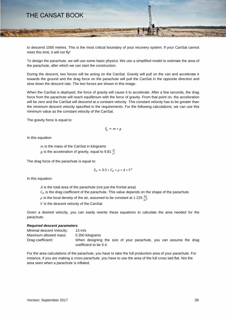
During the descent, two forces will be acting on the CanSat. Gravity will pull on the can and accelerate it
towards the ground and the drag force on the parachute will pull the CanSat in the opposite direction and
slow down the descent rate. The two forces are shown in this image.
When the CanSat is deployed, the force of gravity will cause it to accelerate. After a few seconds, the drag
force from the parachute will reach equilibrium with the force of gravity. From that point on, the acceleration
will be zero and the CanSat will descend at a constant velocity. This constant velocity has to be greater than
the minimum descent velocity specified in the requirements. For the following calculations, we can use this
minimum value as the constant velocity of the CanSat.
The gravity force is equal to:
𝐹𝑔 = 𝑚 ∗ 𝑔
In this equation
𝑚 is the mass of the CanSat in kilograms
𝑔 is the acceleration of gravity, equal to 9.81 𝑚
𝑠2
The drag force of the parachute is equal to:
𝐹𝐷 = 0.5 ∗ 𝐶𝐷 ∗ 𝜌 ∗ 𝐴 ∗ 𝑉2
In this equation:
𝐴 is the total area of the parachute (not just the frontal area)
𝐶𝐷 is the drag coefficient of the parachute. This value depends on the shape of the parachute.
𝜌 is the local density of the air, assumed to be constant at 1.225 𝑘𝑔
𝑚3.
𝑉 is the descent velocity of the CanSat
Given a desired velocity, you can easily rewrite these equations to calculate the area needed for the
parachute.
Required descent parameters
Minimal descent Velocity: 13 m/s
Maximum allowed mass: 0.350 kilograms
Drag coefficient: When designing the size of your parachute, you can assume the drag
coefficient to be 0.4.
For the area calculations of the parachute, you have to take the full production area of your parachute. For
instance, if you are making a cross parachute, you have to use the area of the full cross laid flat. Not the
area seen when a parachute is inflated.

Version: September 2017 40
Semi-spherical parachute design
A semi-spherical appearance is the most common shape for a parachute. Although it is not hard to make one,
it can be quite time-consuming to get the right shape. The figure below should help.
n stands for the number of parts needed
r stands for the radius of the parachute.
Cross parachute design
Instead of using a semi-spherical-shaped parachute, you can also
choose a cross shape. The advantage of this shape is that it’s easy
to make. If you want to know more about cross-shaped parachutes,
you can check the following link:
www.nakka-rocketry.net/xchute1.html
Parapent
A parapent shaped parachute acts rather like a wing. Because of its
shape you can use it to steer. The design of a parapent is more
complex than that of the other shapes mentioned. You will have to do
some more research if you wish to use this type of parachute.

Version: September 2017 41
Flat parachute design
The most commonly available parachutes are in fact created from standard two-dimensional flat geometric figures, such as hexagons or octagons.
From above, you can see that the parachute consists of 8 equal triangles. Hence, the total area for the
parachute would be 𝐴 = 8 ∗ 𝐴𝑇, where the area of one triangle is 𝐴𝑇 = 𝑠 ∗ℎ
2. By combining these two
equations, we get 𝐴 =8∗𝑠∗ℎ
2. You can read more about how to calculate the area of a flat parachute at:
www.sunward1.com/imagespara/The%20Mathematics%20of%20Parachutes%28Rev2%29.pdf
As soon as you know the total area (A) together with the drag coefficient (CD), you can easily determine the
descent rate for your CanSat. Perform some drop tests to check if your calculations are accurate and to find
the terminal velocity.
Other recovery systems
There are also different options when recovering an object. Opportunity (Mars exploration rover B) used
airbags for its landing on Mars (see below). This is based on the same principle as a parachute, namely
increasing area to increase drag and therefore slow down the vehicle. Airbags have the additional
advantage that they soften the landing.

Version: September 2017 42
Apart from these systems, there are also recovery systems that use lift-induced drag. This type of drag is
used in airplanes and helicopters. Auto rotation, a recovery system researched by many including NASA, is
based on the movement of helicopter blades. One big advantage of this system would be that it is steerable
to a certain location. An example of these blades is shown in the figure below.

Version: September 2017 43
CanSat Competition tips Based on experiences of teams competing in other CanSat competitions, we would like to offer you some
extra tips and tricks to get you well prepared for the CanSat competition.
Tips on your CanSat design:
- The temperature sensor for your primary mission must measure the air temperature outside the
CanSat. If the sensor is hidden away too much within your CanSat, the measuring results may be
impacted negatively, so that no proper analysis can be performed. Take this into account in your
CanSat design.
- During previous launching events, it became clear that the CanSats are difficult to trace in the
heathland when trying to recover them after launch. As a result, the CanSats of several teams were
never recovered. Using a sound signal (e.g. a beeper) as a recovery system increases the likelihood
of recovery.
- Use a bright colour for your parachute that contrasts sharply with the background. This improves
your chance of being able to see your CanSat easily during the flight and being able to follow it with
your Yagi antenna.
Tips for your outreach programme:
- Contact local media. Go to www.ruimtevaartindeklas.nl/cansat for more background and other
information about the project.
- Use social media to reach a wider public. Select the right hashtags: #cansat, #cansatNL #ESERO.
Tag on Twitter: @eseroNL, @NEMOamsterdam and @NSO. Tag on Facebook and Instagram:
@nemosciencemuseum. In this way we can like/share your messages. And, of course, follow us too
to share our messages about the competition!
- If you have any questions about the media/press, e-mail them to [email protected].
Tips that last year’s participants wish to pass on:
- The most common tip: prepare properly, start on time and draw up a good planning schedule! You
will need a lot of time. Be organised and work hard.
- Test everything thoroughly and often: test and control your design and make sure that it fits the
requirements and works according to plan.
- If you encounter a problem that you cannot solve, ask for help on time, e.g. from your teacher.
- Make sure you have tools with you on the test and launch days in the case of an emergency
(e.g. having to resolder wires at the last minute).
- If you suffer setbacks, always keep going. Giving up is not an option. Think in terms of solutions
rather than problems. Persevere and you will succeed!
- And the most important: have fun!