the cast structure of high-speed steel
TRANSCRIPT

THE CAST STRUCTURE OF HIGH-SPEED STEEL
E. INFSON & G. HOYLE
Metallurgy (General) Divisional Laboratory, Sheffield
Abstract
The cause and effects of the formation of coarse
cellular carbides in high-speed steels are reviewed
and attention is drawn to possible methods of in-
vestigating the problem and perhaps eliminating it.
Introduction
0
NE of the greatest problems en-
countered in the manufacture anduse of high-speed steel is the forma-
tion (luring casting of a gross cellular carbide
network, particularly near the centre of
large ingots. A section from an ingot withsuch defects is shown in Fig. 1, in which it is
seen that there are quite large areas of
carbide. Microscopic examination of this
ingot showed that near the edge the struc-
ture was quite fine-grained ( FIG. 2 ) whereasat the centre the grain size is large ( FIG. 3 )
and there are large colonies of eutectic.
Edge of Ingot
Centre of Ingot
FIG. 1 - HALF TRANSVERSE SECTION OF HIGH-
SPEED $TEEL INGOT SHOWING MASSIVE CARBIDE AT
CENTRE. X }
74tAL
X. - . MI. ^"VL
orrr0,
FIG. 2 - STRUCTURE NEAR EDGE OF INGOT S HOWN
IN FIG. 1. < 100
Also there is a marked coring effect in the
primary dendrites themselves. It is theeutectic colonies shown in Fig. 3 which give
rise to the segregated appearance of Fig. 1.
The phenomenon of poor carbide distri-
bution has often been referred to as carbide
segregation: this is, in fact, rather a mis-
nomer, since it is confirmed by numerous
methods1,2 that the carbon content of high-
speed steel ingots is practically uniform
throughout, and also that there is no ap-preciable difference in the proportion of
carbide ( eutectic) in the structure at the
edge and centre.
The elimination of the gross eutectic net-
work is essential if a good quality high-speed
steel tool is to be produced. The carbide in
high-speed steel is, however, very complex
and, unlike cementite in ordinary engineering
333
334 SYMPOSIUM ON PRODUCTION, PROPERTIES & APPLICATIONS OF STEELS
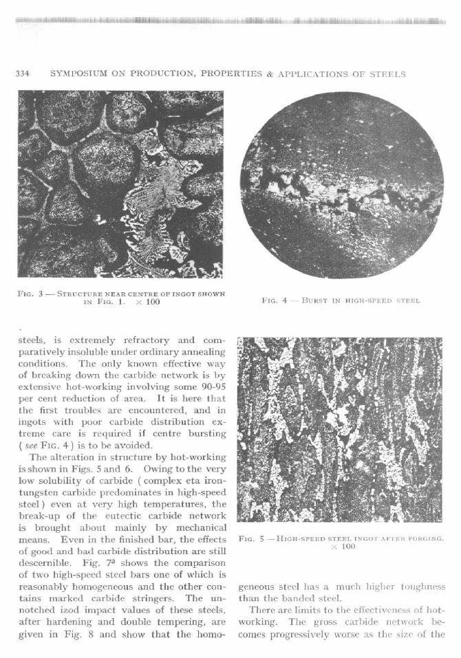
FIG. 3 - STRUCTURE NEAR CENTRE OF INGOT SHOWNIN FIG. 1. X 100
steels, is extremely refractory and com-
paratively insoluble under ordinary annealing
conditions. The only known effective wayof breaking down the carbide network is by
extensive hot-working involving some 90-95
per cent reduction of area. It is here that
the first troubles are encountered, and in
ingots with poor carbide distribution ex-
treme care is required if centre bursting
see FIG. 4) is to he avoided.
The alteration in structure by hot-working
is shown in Figs. 5 and 6. Owing to the very
low solubility of carbide (complex eta iron-
tungsten carbide predominates in high-speed
steel ) even It very high temperatures, the
break-up of the eutectic carbide network
is brought about mainly by mechanical
FIG. 4 - i;liLIST IN NIGH-SPIA D STEEL
means, Even in the finished bar, the effects FIG. 5 -HIGH-SPEED STEEL INGOT AFTER FORGING.
of good and had carbide distribution are stilldescernible . Fig. 73 shows the comparisonof two high-speed steel bars one of which is
1001-1
reasonably homogeneous and the other con- geneous steel has a much higher toughness
tains marked carbide stringers. The un- than the banded steel.
notched izod impact values of these steels, There are limits to the effectiveness of hot-
after hardening and double tempering, are working. The gross carbide network be-
given in Fig. 8 and show that the homo- conies progressively worse as the size of the

I- ESON & HOYLE, - CAST STRUCTURE OF HIGH-SPEED STEEL
-MAY S[4nE e^ [V lrMP
4
I6 • "t-i-=' Ob
64
6s
a 6a
2
SW 520 $40 560 590 600TEMPERING TEMPERATURE. -C.
620
335
COMPARISON OF UN-NOTCHED 1200 TESTS 01 4_
AND NON -SEGREGATED HIGH SPEED STEEL
FIG. 6 - As FIG . 5, WITH GREATER DEGREE OF
WORKING. X 100
FIG. 7 - COMPARISON OF 113GH -SPEED STEEL BARS
SHOWING GOOD (ON THE RIOIRT) AND BAD CARBIDE
DISTRIBUTION
ingot increases, and in ingots greater than
about 14 in_ sq. it is so pronounced that
no convenient amount of hot-working willentirely eliminate the cast structure. If one
considers a quite normal requirement for,
FIG. 8 - PROPERTIES OF BARS S13OWN IN FIG. 7
say, a 6 in. diameter cutter blank, it can be
seen that to achieve a 90-95 per cent reduc-tion of area in hot-working it would be
necessary to start with a 24 in. ingot. This
is practically the limit in size of commercial
high-speed steel ingots, and it will be appre-ciated that new requirements by engineers
for 9 in. and even 12 in. diameter blanks areinevitably leading to greater difficulty in
producing sound blanks free from the so-called centre weakness. In the case of suchtools as milling cutters it is, of course,
practicable to make large blanks by up-
setting, but this is not possible for blanksfor many tools such as hobs. Fig. 9 shows
a typical drill which has failed due to poor
carbide distribution ( probably .%,itli in-
sufficient reduction ).Almost from the inception of high-speed
steels some 50 years ago, steel-makers have
endeavoured to overcome the difficulty byattempting to refine the cast structure in the
ingot. It has proved to be a most intract-able problem and little progress has been
made apart from relatively minor improve-
ments brought about by applying stricter
control to steel-making processes. There
is good evidence, however, that the only

336 SYMPOSIUM ON PRODUCTION, PROPERTIES & APPLICATIONS OF STEELS
FIG. 9 - FAILU RE IN IIIGII -SPEED STEEL DRILL DUE
TO POOR CARBIDE DISTRIBUTION
completely satisfactory answer to the problemwould be the discovery of some method ofmodifying the cast structure of high-speed
steel. B.I,S.R,A. have, therefore, under-
taken to examine the question again in the
light of more recent theories of nucleationand growth of crystals and are employing
new or improved techniques which have
become availahie.
The Constitution of High - speed Steel
High-speed steels are complicated alloys
of Fe, W, Cr and V, containing usually
between 0•S and 0.8 per cent carbon. The
basic alloy composition which has found
universal favour is still the one introduced
by Taylor and White in 1900, namely W, 18;
Cr, 4 and V, 1 per cent (18-4-1) ; but there
are many variations, the most important of
which are those in which molybdenum
replaces or supplements tungsten. In a
general consideration of the constitution
and behaviour of high-speed steels the
many variations in composition may be
largely ignored and attention concentrated
on the basic 18-4-1 type. It has been
customary to consider high-speed steels as
approximating to ternary iron-tungsten-
carbon alloys by supposing that chromium,
vanadium and molybdenum behave similarly
to tungsten. The tungsten equivalence of
each of these elements differs from unity
and it has been claimed4 that I per cent of
Cr, D1o, or V is equivalent respectively to
about 0.5, 1.5 or 5-0 per cent of tungsten,
(ioldschmidt5 does not entirely agree with
this, particularly in regard to chromium,
which dots not appear to behave in quite
the same manner as tungsten. However,
as a first approximation an 18-4-1 high-speed
steel can he considered as being equivalent
to a 25-26 per cent tungsten-iron-carbon
alloy.
Much work has been done on the con-stitution of ternary Fe-W-C alloys, but very
little of this is complete or confirmed. The
most widely accepted data were provided byTakedaM in 1930 and 1931. On the basis
of these data a section through the ortliodoxternary Fe-W-C system at 25 per cent W and
parallel to the Fe-C side of the diagram has
been constructed. Another variation of the
diagram was published by Grossmann and
Bain4, who prepared a pseudo-binary diagram
of iron against complex carbide, Later
Murakaini and Hatta8 made an attempt to
give a closer approximation to the true state
of affairs by preparing it binary section
through a quaternary Fe-Cr-W-C system at
18 per cent W and 4 per cent Cr. Sub-
sequently Kuo9 has proposed a modification
of Murakami and Hatta's diagram. The
version according to Kuo is reproduced in
Fig. 10. No account is taken of vanadium
in this diagram, but Kuo suggests that, from
a consideration of the known behaviour of
this element, adequate correction for its
presence is obtained by moving the respective
points on the diagram slightly towards higher
carbon contents.
In the fully worked and annealed condi-
tion, an 18-4-1 alloy containing 0-7 per cent C

INESON & 11OVLF -CAST STItUCTURL OF 1-11GH-SPEED STEEL 337
1700
1500
1300
uoo
900
700
1r•1.*F
L F*A
FL+
+A+
F4 a+F ? A A+
r
f.,e
-
(3) Colonies of eutectic occupying theinterstices between the crystals andconstituting the cellular network.
(4) Isolated carbide particles possibly
vanadium carbide.
Freezing of Ingots
In the molten condition, high-speed steelis generally believed to be a practically uni-form liquid throughout . The various ele-ments present in addition to iron, such as C,Mn, Si , S, F, Cr , W, Mo and V, are essentiallyall dissolved. From time to time the viewhas been expressed that this is not entirelytrue and there have been suggestions thatunder certain conditions liquid high-speedsteel will separate into two immiscible layersof different alloy content . No concrete evi-dence has ever been produced to supportthese views. However , whether or not thesteel is completely uniform in the liquid stateit certainly loses uniformity upon freezing asshown in Fig . 3, from which it is clear thatmarked coring or microsegregation existswithin the primary dendritic regions quiteapart from the major differences in com-position between the primary and eutecticphases.
The cast structure may be relatively coarseor fine, depending on the rate of solidificationin the mould. This in turn depends on thepouring temperature and the rate of coolingin the mould . The use of liquid steel pyro-meters enables pouring temperatures to becontrolled and reproduced to a high degreeof accuracy , but it is not so easy to alter therate of cooling in the mould. With smalleringots some slight acceleration of coolingmay be achieved by the use of copper moulds,or by Water -cooling the mould: the chillingeffect is, however, offset to some extent dueto the fact that the initial chilled layer is im-mediately separated from the mould wall dueto shrinking and leaves an air gap.
In any event the effect of chilling isnegligible at the centre of large ingots -
o 0-2 0 4 0-6 0-e 1.0 1-2 14 1.6 1•e 2.0CARBON CONTENT %
FIG. 10 --- CONSTITI'TION DIAGRAM OF THE Ve-1V-
Cr-C SYSTEM. SECTION AT 18 PER CENT NV AND
4 PER CENT Cr (AFTER MURAKAMI AND HATTA,
MODIFIED By Kuo ). A - AUSTENITE; F --- FER-
RITE; L- LIcuiD; i7 - (Fe.\V)0C; 0- Fe,C
consists essentially of ferrite and eta carbide.The latter is predominantly a complex
carbide having the formula Fe4W2C orFe3\W'3C - perhaps better expressed as "'16C or
Fe.W )6C. It will be seen from Fig. 10that theoretically the phase changesoccurring during solidification of such an
alloy will, allowing for the presence of vana-
dium, be indicated by a vertical linethrough A, or a line slightly to the left or
right of A depending on the exact composi-
tion.The reactions at equilibrium vary slightly
according to the exact position on the dia-
gram, but the conditions in practice are such
that equilibrium is never attained and the
following phases are present in the solidified
steel:
(1) Areas which were of delta iron at high
temperature and which appear asislands of delta eutectoid - i.e. finely
dispersed carbide.
(2) Bands surrounding the islands -
believed to be austenite or martensite
formed by transformation.

338 SYMPOSIUM ON PRODUCTION , PROPERTIES & APPLICATIONS OF STI.FLS
which is the position where the refining
effect is most needed if any beneficial resultis to be obtained. We must, therefore,
consider other means of inducing a fine struc-ture and it is helpful in this connection to
consider the conditions governing the forma-
tion of crystals from the melt.
to a size in excess of the critical value, it willbe stable and can grow with a decrease infree energy. Any reduction in the ` energybarrier ' will , therefore , lead to an increasein the frequency with which stable crystal-lites form in the melt, and thus to a refine-ment of the grain size in the solid metal.
Refinement of the Structure
If we consider the free energy changes as a
crystallite forms, we find that the total free
energy change ( AG' ) is the sum of two
terms -first, a. positive term (see FIG. 11 ) 10
AG., representing the energy of formation
of the new interface and Toughly proportional
to the square of the diameter of the crystal-
lite, and, secondly, a negative term AG"
representing the energy of the phase change
at a given degree of undercooling, and pro-
portional to the cube of the crystallite dia-meter. The resulting total free energy
change AG' thus shows a maximum corres-
ponding to a certain critical particle size.
Now, if a solid particle smaller than the
critical size is formed in the melt, it will be
unstable since any increase in its size ,vould
be accompanied by an increase in free energy
and will tend to redissolve in the liquid.
However, if a particle does form and grows
FIG. 11 - FREE ENERGY CHANGES DURING SOLIDI-
FICATION
Homogeneous Nucleation
The dotted curves in Fig. 11 show theeffect on AG" and AG' of undercooling the
melt: AG, decreases to AG', thus reducingthe value of AG' to AG" and reducing the
critical nucleus size for stable growth and
thereby increasing the probability of crystal-lite formation. AG.', remains approximately
constant during tuulercooling.
This indicates that refinement of structure
by undercooling is possible w lien the nuclea-
tion is homogeneous - that is when each
nucleus is formed from the melt and there is
no effect due to foreign substances. In
practice it is very seldom that nucleation is
homogeneous", and there an, inevitably
effects due to mould tc alls, etc., which prevent
undercooling and induce some measure of
heterogeneous nucleation. Xevertheless, the
principle of undercooling can be applied
to some extent by rapid cooling, and this
can best be achieved if a casting temperature
as low as possible is used - as mentioned
previously, however, this effect is negligible
at the centre of a large ingot.
Effect of Heterogeneous Nucleation
An alternative method of reducing the
energy barrier is by the addition of foreign
particles to the melt. Under favourable
conditions, the presence of foreign nuclei
can lead to a reduction in AG" ( set., Fi(:. 12 ),
thus once again causing it reduction of AG'
to AG"' with a similar effect in increasingthe frequency of crystal formation.
Attention is being focussed on the method
of nucleation as being the most likely process

I NESON & 11()YLI . - CAST S"TRUCTSImE OF HIGH-S1 '1.F:D STEEL
FIG. 12 - FREE ENERGY CHANGES DURING SOLIDI-
FICATION
to produce grain refinement in the present
instance. In other fields some remarkablesuccesses have been achieved by the appli-cation of this nrethodl--II and much work
has been done in connection with the theory
of the process, and to determine the condi-
tions necessary for a particle to act as anucleus.
The first and most obvious condition isthat the substance selected as an inoculant
must be capable of existing in the melt inthe form of small solid particles at the soli-
dification temperature. It is also essential
that the dispersion of particles is satisfactory,and it is an advantage in this connection if
the inoculant can be formed in the melt byreaction between a component already
present and an 'added substance. Recentwork by Thuryl5 has been described in which
nuclei for refinement of aluminium alloysare formed by additions such as potassium
boron fluoride, which reacts in the melt toproduce aluminium boride: the reaction is
exothermic and does not lower the tempera-
ture of the melt.
The second condition is that the nucleusmust be wetted by the liquid metal, and a
third is that attractive forces should exist
between atoms of the solid metal and the
nucleus; this factor must not, however, be
339
too great, or solution of the nucleus would
occur by the formation of intermetallic
compound.The remaining condition is that the molten
metal should he able to solidify on the arti-
ficial nucleus, or nucleation catalyst, just asif the nucleus were in fact a particle of the
solid metal. In nature numerous examplesare found where a crystal has grown on a
crystal of another substance with a specific
orientation relationship. This phenomenon is
termed oriented overgrowth or epitaxy, and
the present subject - in which crystallites
are supposed to form and grow on an arti-
ficial nucleus in a similar way - has been
referred to as isotaxy, or epitaxial nucleation.The conditions under which such a processcan take place have been the subject of much
attention and several mathematical treat-ments have been published16.
The criterion which is considered to he of
major importance is that for nucleation to
take place, the crystal structure of the nucleus
and of the solidifying metal should be suchthat there is little or no strain at the interface
between the two substances in the compound
crystal formed. The concept of lattice dis-
registry, or misfit, is used as a measure ofthe amount of strain at the interface, and is
defined as'6:
s Aa
aV
where ao = lattice spacing in metalcrystal
= lattice spacing in metalnucleus.
This may also be expressed as a percentage,
where
Aa% misfit = 100 per cent
as
It is generally considered that for effectivenucleation a misfit of less than 10 per cent isdesirable : some authorities consider thisfigure to be excessive , and others permitvalues up to 15 per cent . It is also generally

340 SYMPOSIU M ON PRODUCTION, PROPERTIES & APP LICATIONS OF STEELS
accepted that the misfit should he cal- Fig. 15 shows it structure in which some
culated on close-packed planes of the crys- alteration of the normal lial)it has taken
tals under consideration, and that the place. Here, although the actual eutec-
lattice correspondence should be two- tic structure has been hroken, it is still ap-
dimensional. parent that the carbide exist= in large
An example of a two-dimensional lattice colonies.
correspondence is shown in Fig. 13 whereprojections of ( 100) planes of two sub-stances have been superimposed .
Cibulal" has used these principles ex-tensively in a study of grain refinement of
non-ferrous alloys, and Dennison and Tull"
utilized the theory with considerable success
to select an inoculant for Cu-Al alloys con-
taining the beta phase. In the present re-
search, a survey of crystal structures has
been made in an attempt to find suitable
inoculants for the delta phase in high-speedsteel.
It is considered necessary to inoculate the
primary phase rather than endeavour to
induce a modification of the eutectic colonies.
Fig. 14 shows the structure of the eutectic
normally found in high-speed steels, and
4 O D 6 0 D D D 0
® O (0 (0 //Q qD QD
o D o o O 0 O O e
o O O 0 0 0 O 0
0 0 e 0 e e
n (,+7^ 0 00 ® ® © Cl Cl 9)
0 e 0 0 ^' ® t 9) coo 0 0 o 4 / o(b o
^6 Y)e o o e
e(/^ o ^Q,^/(/e ^-y1 0 /^p^l (y^^
e 0 o 0 0 0 0 D 0
(b (bO D o 0 D O
00o re ATOM &C.C. unKl.6 NON "' ATpA .
w ry^i - LA"M[/AL A10M 1
FIG. 14 - N'ORN_\L EUTECTIC IN IIIGH-SFLLD STEEL.
X 100
FIG. 13 - CORRESPONDENCE OF LATTICES OF DIF- FIG . 15-MODIFIED CUTECTIC IN IHGIi-SPEED STEEL,
FERENT SUBST ANCES x 100

1NNI SON & I-IUVLEE: - CAST S I k CTU RE 0 I I1(;1I-SPEEI ) STEEL
Eff ects of Vibration
Mechanical vibrations are known to have animportant disturbing influence on liquid ->-crystal reactions'', and quite mild vibrationscan induce nucleation in undercooled liquidsat temperatures higher than those at which
solidification would occur under conditionsfree from vibration . One theory 's suggeststhat the effect is caused by cavitation, at thecontainer wall or elsewhere, and that wavesof high alternating pressure are formed bythe rushing of liquid into these cavities. Afurther theory suggests that vibration maycause disruption of crystals already presentand thus give rise to an increased numberof nuclei.
Support for this is found in the field ofnon-ferrous metallurgy and various experi-ments have been carried out by manu-facturers to explore the effect of vibrationon the solidification of high-speed steel ingots.No success has been publicly reported, butone interesting result is shown in Figs. 16and 17 . These photographs show the effectof vibration at 50 cycles per second on thestructure of an ingot of high-speed steel's.The cause of the banding effect is not known,but it has been suggested that it may be dueto a resonance phenomenon.
Vibration at ultrasonic frequencies has alsobeen used with some success in metallurgy.
Not Vibrated Vibrated
I'IG. 16 - COMPARISON OF HIGH-SPEED STEEL IN-
GOTS VIBRATED AND NOT VIBRATED DURING SOLIDI-
FICATION
a
0z
b0
At
FIG. 17 - BILLETS PRODUCED FROM FIG. 16
(Figs. 16 and 17 are reproduced by hired pernlissio.' ofMr. J. II'uolnian, Brown-Firth Research Laboratories )
Alder'-'0 reports an experiment in which the
grains in a zinc ingot have been refined in
this way. The chief difficulty in this method
appears to be that of transferring the energy
from the source of vibration to the melt,
and a well-known firm of electronic instru-
ment manufacturers has expressed the view
that the method cannot as yet he applied
economically to any but the smallest ingots
of high-speed steel,
Electromagnetic Stirring during
Solidification
This method has been tried in an attempt
to preserve uniformity in the liquid phaseduring solidification and to assist the freezing
process by bringing the reactants togetherby mechanical means instead of relying on
the slow diffusion processes normally in-volved. On the laboratory scale this has
been achieved by allowing a melt to solidifyin the high-frequency furnace with a powerinput sufficient to stir the metal and yet
sufficiently low to allow cooling to take place.
Very slow cooling was obtained and thestructures were reasonably fine, although
there was inevitably eutectic present and the
normal coring was observed.

11.1 - 111 I'I 1 ' III 1. 11 ll I_ .,. . ..:
142 SV MP(IIS ( UM ON Pk )DI 'CrIUN, l'ROl'LRTIIES & A19'LI(,\1l( )NS uF STEICI 4
Conclusion
The difficulties encountered in this type
of work are manifold: for instance, the high
cost of the steel makes research work ex-
pensive, and manufacturers are under-
standab1v loath to risk the possible wastage
of an ingot weighing, say, half a ton, which
may be worth something in the region of
£ 250. Other difficulties are attributable
to the long annealing and other heat treat-
ment operations required when dealing with
high-speed steel. Nevertheless, manufac-
turers are alive to the problems and they,
as well as l .I.S.R.:A., are actively engaged in
exploring new methods to endeavour to im-
prove still further the high quality of the
tool steels produced in Sheffield --- for it is
here that practically all the high-speed steel
made in Britain is pro(hlce(1.
References
1. SAWYER, C. F., JR., Iron Age, 60 (1947),140-142.
2. B.I.S.R.A. Laboratories and Sheffield Univer-
sity, private communication.
3. STEWART, G. FLETCHER, Traits. A.S.M., 42
( 1950), 714-718.
Jt
4. GROSSMANN & BAIN, High Speed Steel ( Wiley,
New York ), 1931.
5. GOLDSCHMIWT, H. J., J.I. S.I., 170 ( 1952 ),
189-204.
6. TAKEDA, S., Tech. Rep. Tuknku Imp. Univ., 9( 1930 ), 483-514, 627-664.
7. TAKaDA, S., Tech. Rep. Tohoku Imp. Cniv.,
10 ( 1931 ). 42-92.
8. MI UR .AKAMI, T. & IIATTA, A., Sc. Rep. Tohoku
9.
10.
Imp. Univ. lsg Sec. 1936, Honda AnniversaryVolume, 882-895.
KERSIN Kuo, 1. 7.5.1., 181 ( 1955 ), 128-134.
CIUULA, A., J. Inst. Mc! ., 76, Part 4 (1949 ),
321-360.11. HOLLONON, J. H., Thevmodynantics in Physi-
cal :Lletallurgy (A.S.M.), 1950.
12. DENNISON, J. 1'. & TOLL, E. V., J. Ins!. Met.,
81 ( 1952-53 ), 513.
13. REYNOLDS & TOTTLi, J. Inst. Mel., 80 (1951-52 ), 93.
14. Clnl'LA,,/. lust..1lct., 82 ( 1953-54 ), 513-524.15. Tm-RY, \W., Z. ;lleta.llk., 46(7) ( 1955 ), 488-4(4).16. TcxtinuI.r, 1). & VONNEGUT, B., Ind. Eng.
(7,ept., 44 ( 1952 ). 1292-1298.17. TURNOI'LL D., Thcrnlolvna,nics in Physical
Metallurgy (A.S.M.), 1950.
18. Reference included in ( 17 ) as private corn-
munication from 13. Vonnegut,
19. Firth-Brown Research Laboratories, private
20.communication.
ALDER, K., A us t ral. Eng. ( Dec. 8, 1952 ),
53-60.
I