the central trigger control system of the cms experiment ... · trigger objects (e.g., regions of...
TRANSCRIPT

Preprint typeset in JINST style - HYPER VERSION
The Central Trigger Control System of the CMSExperiment at CERN
A. Taurok∗, B. Arnold, H. Bergauer, M. Eichberger, J. Erö, Ch. Hartl†, M. Jeitler,K. Kastner, I. Mikulec, B. Neuherz, M. Padrta, H. Sakulin†, J. Strauss, C.-E. Wulz
Institute of High Energy Physics of the Austrian Academy of Sciences,Nikolsdorfergasse 18, A-1050 Vienna, Austria
J. VarelaLIP - Laboratório de Instrumentação e Física Experimental de Partículas and IST - InstitutoSuperior Técnico, Lisbon, Portugal
W. H. Smith
Department of Physics, University of Wisconsin, Madison, WI, USA
ABSTRACT: The Large Hadron Collider will deliver up to 32 million physics collisions per sec-ond. This rate is far too high to be processed by present-day computer farms, let alone stored ondisk by the experiments for offline analysis. A fast selection of interesting events must thereforebe made. In the CMS experiment, this is implemented in two stages: the Level-1 Trigger of theCMS experiment uses custom-made, fast electronics, while the experiment’s high-level trigger isimplemented in computer farms. The Level-1 Global Trigger electronics has to receive signalsfrom the subdetector systems that enter the trigger (mostly from muon detectors and calorimeters),synchronize them, determine if a pre-set trigger condition is fulfilled, check if the various subsys-tems are ready to accept triggers based on information from the Trigger Throttling System and oncalculations of possible dead-times, and finally distribute the trigger decision (“Level-1 Accept”)together with timing signals to the subdetectors over the so-called “Trigger, Timing and Control”distribution tree of the experiment. These functions are fulfilled by several specialized, custom-made VME modules, most of which are housed in one crate. The overall control is exerted by thecentral “Trigger Control System”, which is described in this paper. It consists of one main moduleand several ancillary boards for input and output functions.
KEYWORDS: Control and monitor systems online, Trigger concepts and systems (hardware andsoftware).
∗Corresponding author; E-mail: [email protected]†Now at CERN, Geneva, Switzerland.

Contents
1. Overview of the CMS Global Trigger 1
2. Role of the central Trigger Control System 3
3. Trigger Control logic 43.1 DAQ partition controllers (DAQ-PTC) 53.2 Time Slice distribution 73.3 Trigger Throttle logic 7
3.3.1 Status signals 83.3.2 Throttle rules 8
3.4 State Machine 83.5 Trigger signal distribution to subdetectors 103.6 Calibration circuit 103.7 Pseudo-random trigger 113.8 Luminosity segments 113.9 Monitoring counters 113.10 Status simulation and monitoring 11
4. Hardware implementation 11
5. Control and monitoring software 135.1 XDAQ executives and applications 145.2 Trigger Supervisor Cells 145.3 Global Trigger online software overview 145.4 Configuration and control services 155.5 Monitoring services 165.6 Graphical User Interfaces 16
6. Performance and results 17
1. Overview of the CMS Global Trigger
The Compact Muon Solenoid (CMS) experiment at CERN, the European Organization for NuclearResearch, is designed to study physics at TeV scale energies accessible at the Large Hadron Collider(LHC). The Global Trigger [1–3] is the final stage of the CMS Level-1 Trigger [4]. For each LHCbunch crossing it has to take the decision to reject or to retain a physics event for further evaluationby the High Level Trigger [5]. For normal physics data taking the decision is usually based on
– 1 –
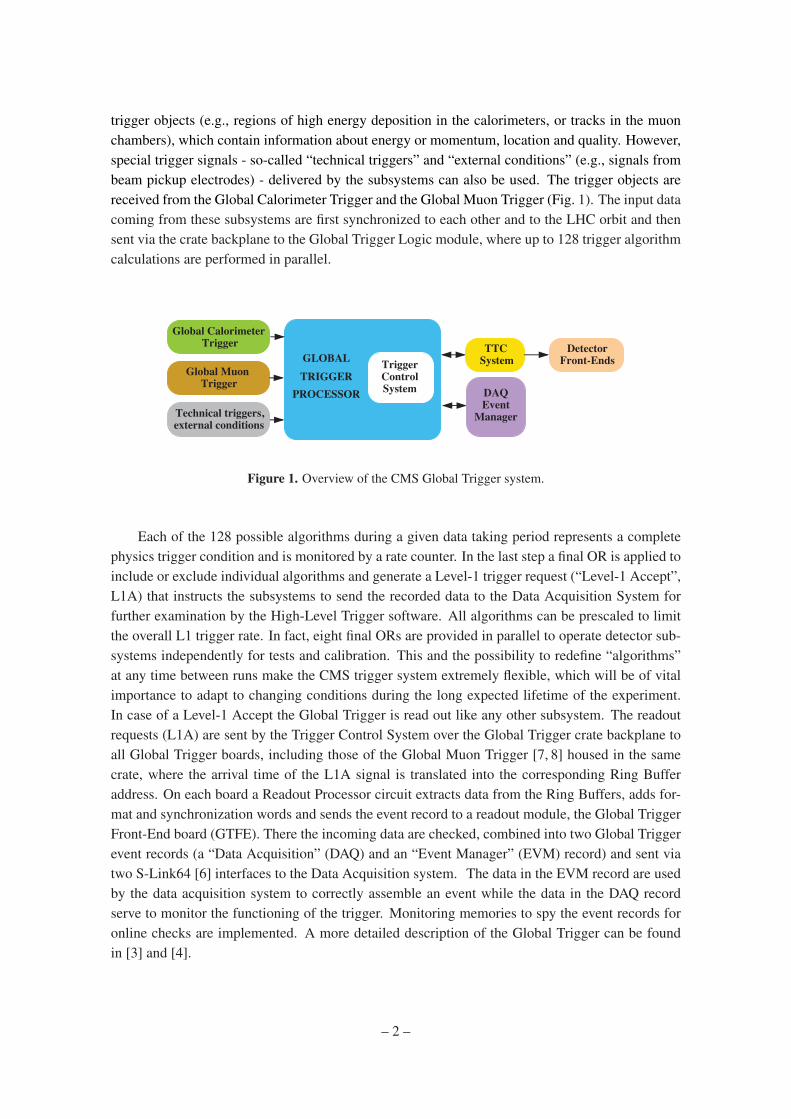
trigger objects (e.g., regions of high energy deposition in the calorimeters, or tracks in the muonchambers), which contain information about energy or momentum, location and quality. However,special trigger signals - so-called “technical triggers” and “external conditions” (e.g., signals frombeam pickup electrodes) - delivered by the subsystems can also be used. The trigger objects arereceived from the Global Calorimeter Trigger and the Global Muon Trigger (Fig. 1). The input datacoming from these subsystems are first synchronized to each other and to the LHC orbit and thensent via the crate backplane to the Global Trigger Logic module, where up to 128 trigger algorithmcalculations are performed in parallel.
Global CalorimeterTrigger
Global MuonTrigger
GLOBALTRIGGER
PROCESSOR
TriggerControlSystem
TTCSystem
DetectorFront-Ends
DAQ Event
ManagerTechnical triggers,external conditions
Figure 1. Overview of the CMS Global Trigger system.
Each of the 128 possible algorithms during a given data taking period represents a completephysics trigger condition and is monitored by a rate counter. In the last step a final OR is applied toinclude or exclude individual algorithms and generate a Level-1 trigger request (“Level-1 Accept”,L1A) that instructs the subsystems to send the recorded data to the Data Acquisition System forfurther examination by the High-Level Trigger software. All algorithms can be prescaled to limitthe overall L1 trigger rate. In fact, eight final ORs are provided in parallel to operate detector sub-systems independently for tests and calibration. This and the possibility to redefine “algorithms”at any time between runs make the CMS trigger system extremely flexible, which will be of vitalimportance to adapt to changing conditions during the long expected lifetime of the experiment.In case of a Level-1 Accept the Global Trigger is read out like any other subsystem. The readoutrequests (L1A) are sent by the Trigger Control System over the Global Trigger crate backplane toall Global Trigger boards, including those of the Global Muon Trigger [7, 8] housed in the samecrate, where the arrival time of the L1A signal is translated into the corresponding Ring Bufferaddress. On each board a Readout Processor circuit extracts data from the Ring Buffers, adds for-mat and synchronization words and sends the event record to a readout module, the Global TriggerFront-End board (GTFE). There the incoming data are checked, combined into two Global Triggerevent records (a “Data Acquisition” (DAQ) and an “Event Manager” (EVM) record) and sent viatwo S-Link64 [6] interfaces to the Data Acquisition system. The data in the EVM record are usedby the data acquisition system to correctly assemble an event while the data in the DAQ recordserve to monitor the functioning of the trigger. Monitoring memories to spy the event records foronline checks are implemented. A more detailed description of the Global Trigger can be foundin [3] and [4].
– 2 –

2. Role of the central Trigger Control System
The central Trigger Control System (cTCS) has two main tasks [9]:
• it controls the Level-1 Accept rate and limits it if necessary;
• it provides control signals for all the readout and trigger electronics.
To achieve the first task, the cTCS can receive status information from the readout electronics aswell as from the Data Acquisition System (DAQ) and trigger electronics via the so-called TriggerThrottling System (TTS). The front-end readout electronics uses a “synchronous TTS” (sTTS) andthe Trigger Control System also has an “asynchronous TTS” (aTTS) input intended to receivethrottling signals from the DAQ side. Currently, only the sTTS path is used; if the DAQ is notready to accept data, instead of issuing an aTTS signal it just exerts backpressure on any one ofthe front-end readout systems, which is then propagated to the Global Trigger via the sTTS. In thecase of some of the subsystems (in particular, the silicon strip tracker) this is not sufficient due tothe limited size of the subdetector buffers and the non-negligible signal propagation time betweendifferent parts of the experiment. Therefore, local “state machines” (“emulators”) implemented indedicated VME modules (installed next to the cTCS crate) are used to emulate the occupation of thefront-end buffers of individual subsystems. When a subsystem is not ready to accept triggers, theyare temporarily inhibited. In addition a “throttling” circuit guarantees that triggers are distributedaccording to well-defined rules specifying the maximum admissible instantaneous and averagerates of L1A signals (in other words, the rates of L1A signals measured over several differenttime windows; see section 3.3 below), and thus to minimize the danger of buffer overflows insubsystems. The central trigger control also monitors and records the deadtime of the varioussubsystems (see section 3.9 below).
The second main task of the cTCS, in addition to distribute the L1A signals to all subsys-tems, is to deliver special control signals for reset commands, calibration purposes, and tests(“Bunch Crossing Zero” (BC0) marking the beginning of each proton orbit in the LHC, resyn-chronization and reset commands, and other so-called “BGo” or control commands). These signalsare distributed via the “Trigger, Timing and Control” (TTC) distribution tree of the CMS experi-ment [10–12]. Thus, the functions of the cTCS are to
• limit the trigger rate, according to programmed Trigger Rules, based on
– signals from subsystems;
– signals from subsystem emulators;
• generate and distribute control signals;
• generate calibration and test trigger sequences;
• monitor the dead time of all subsystems.
– 3 –

3. Trigger Control logic
An overview of the Trigger Control logic is given in Fig. 2 and has been briefly described in [13].Starting from the connections in the Global Trigger crate itself (center left) and proceeding in aclockwise direction, the central Trigger Control board is interfaced with the following main mod-ules and systems:
CentralTrigger Control
TCS board
FDL
8 FinalOR FMM
TTCci
L1A, BGo commands
LHC interface
BC0 and CLK
Distribution
Detector Partition
32 PARTITIONS
L1A record Status Signals
ORBIT
CLK
EVENT MANAGER
8 DAQ-Partitions
aTTS
8 8
TIM
CLK,BCR
BC0
CLK
Front-End Driver crate
FMM
TTCci
EMULATOR
Signals to EMU‘s
Tracker Partition
Global Trigger Crate
STATUS SIGNALS Front-End Driver crate
Front-End Driver crate
Front-End Driver crate
Front-End Driver crate
Figure 2. Schematic representation of the trigger control logic.
• The TCS board receives timing information from the LHC interface via the TTC system’sTTCmi (“TTC machine interface”) and the timing module (TIM) housed in the Global Trig-ger crate.
• Detector subsystems send “ready", “busy” and other warning signals via the sTTS (syn-chronous Trigger Throttling System).
• Trigger decisions are received from the FDL (Final Decision Logic) module in the GlobalTrigger crate.
• The TCS board can receive warnings about high buffer occupancies from the DAQ via theaTTS (asynchronous Trigger Throttling System; not implemented in CMS at the moment).
• Emulators calculating the state of front-end derandomizing buffers send a warning to cTCSif the buffers are close to getting full.
– 4 –

Figure 3. The 9U VME crate housing the various modules of the CMS Global Trigger system.
• cTCS sends trigger signals (L1A = Level-1 Accept) to TTCci modules of detector partitions(defined below).
• cTCS sends control signals (“BGo” commands) to TTCci modules of detector partitions:Start Run, Stop Run; Resynchronize, Event Counter Reset, Bunch Crossing Zero (BC0),Orbit Counter Reset, etc. BC0 could also be received directly from the LHC clock interface(see Fig. 2) but to ensure proper synchronization all TTCci modules in CMS are set up to getit from cTCS. The clock, however, is always derived directly from the LHC clock interfacein order to ensure a high-quality signal.
The hardware implementation of this system is shown in Fig. 3. Left of the center one seesthe electronic module of the Trigger Control System (the module with the red LED display at thetop) with all its cable connections.
3.1 DAQ partition controllers (DAQ-PTC)
The Trigger Control logic reflects the optional segmentation of the CMS readout system into8 DAQ-partitions (Fig. 4).
The Global Trigger Processor therefore generates up to 8 Final-OR signals in parallel and theTCS chip contains 8 DAQ-Partition Controllers (DAQ-PTC) running independently of each other.The Run Control Software can start and stop the DAQ-PTCs without any restrictions except thatonly one DAQ partition is allowed to trigger at a given bunch crossing. This allows to use parts of
– 5 –

Partitioning in TCS
TRIGGERMERGER
B-GoGENERATOR
DAQ-PTC0DAQ-Partition Controller
EMULATORSIGS
CALIBRATION& TEST
EVM RECORDFORMATTING
MONITORINGCOUNTERS
STATE MACHINE
Connect L1A, 4B-Go to 32 partitions
TTCci_31+TTCex
EMULATORS_0...7
TCSFPGA
MULTIPLEXERfor
EVM RECORDS
DAQ_0...7
EVENTMANAGER
COMMONTHROTTLE
LOGIC
FIN_OR_0
FIN_OR_7
FMM_0-7
32 partitions
32 partitions
CLK, L1A,BC0... to Emulators
TCS status to aTTS 0...7
For each DAQ-PTC merge status signals of connectedpartitions and corresponding DAQ-partition.
Each partition is connected onlyto one DAQ-PTC.
FMM=FastMonitoringModule
TTCci_0+TTCex
FMM_8-15 FMM_16-238 DAQ partitions
sTTSaTTS
Figure 4. Partitions of the Trigger Control system.
the detector (which can be freely assigned to any of the DAQ partitions) independently, which isvery useful for testing different subsystems at the same time.
In practice, this system is not frequently used at present because the CMS data acquisitionsystem is not divided into partitions and stand-alone tests of individual subsystems are mostlyperformed by using special “Local Trigger Controller (LTC)” boards. However, the implementationhas been foreseen in the trigger software and all functions with regard to configuration and controlof the eight DAQ-Partition Controllers are in place. Thus, only an upgrade of the data acquisitionsystem and integration with the run control system’s command chain is needed to make full use ofthis feature. One significant advantage over using separate LTC boards would be that all latencieswould be exactly the same as during global data taking.
The front-end and trigger electronics is divided into up to 32 detector partitions accordingto the 32 “trees” of the TTC system (also briefly called “partitions”, in contrast to the “DAQ-partitions” defined above). All crates connected by TTC fibers to the same TTCci board (VMEinterface board for the TTC system) belong to the same detector partition. Each detector partitionis connected to only one DAQ-partition at a time. The corresponding DAQ-Partition Controller(DAQ-PTC) receives the Status Signals of the connected partitions and provides the L1A signaland BGo-commands (for calibration etc.). For example, the RPC-positive-endcap and positive-
– 6 –

CSC partitions (two muon detector subsystems made of resistive plate and cathode strip chamberscovering partly the same region) could be connected to DAQ-PTC2 for running alignment pro-cedures, and all four Tracker and all six ECAL partitions could be connected to DAQ-PTC3 forcalibration measurements. For a normal physics run, DAQ-PTC0 controls all partitions and usesthe Final-OR 0 signal as the common physics trigger.
Each Partition Controller (PTC) serves one “DAQ partition” and provides all functions to runa group of detector partitions independently. It consists of:
• a Trigger Merger that combines all trigger sources (Final-OR from trigger logic as well asRandom, Test and Calibration Triggers produced by the Trigger Control System) into a L1Asignal;
• a PTC State Machine that runs the control procedures according to the states of the connectedpartitions;
• a counter for the Bunch Crossing number;
• a Bunch Crossing Table that defines at which bunch crossing numbers in the orbit BGo com-mands and calibration triggers will be sent; it also defines periods in the orbit where triggersare suppressed (such as during the gaps within an LHC orbit where no particle collisions areexpected);
• a Calibration Logic system to run calibration cycles;
• a Periodic Signal Generator for Bunch Crossing Zero (BC0) and Start of Gap commands aswell as calibration cycles, periodic test triggers and Private Orbit signals (Private Orbits areperiods corresponding to individual LHC orbits which are reserved for subsystem tests andwhere normal trigger signals are disabled);
• a Random Trigger Generator;
• a common counter for the Orbit number, which will be reset only by PTC0 when starting anew data taking run.
3.2 Time Slice distribution
The Trigger Controller distributes the beam time between the active DAQ-partitions in round-robinmode, activating them consecutively for programmable periods of time. The length of a periodmay vary between 10 and 2550 orbits. During inactive periods each DAQ-PTC inhibits L1As andcalibration cycles but still sends control commands to its detector partitions and also receives andmonitors status signals in the usual way.
3.3 Trigger Throttle logic
A common TTS (Trigger Throttling System) circuit prevents excessive instantaneous trigger ratesfor all partitions to avoid problems in the readout system. On the one hand, the Trigger ControlSystem reacts to status information from the various subsystems of the CMS experiment. On theother hand, and independent of the momentary state of the systems, instantaneous trigger rates are
– 7 –

limited according to a set of pre-set throttle rules allowing a defined number of trigger signals pertime period.
3.3.1 Status signals
The synchronous Trigger Throttling System (sTTS) interacts with detector partitions while theasynchronous aTTS allows to receive status signals from the DAQ system. All eight DAQ partitionsare served by this common system.
The Trigger Control System receives the status signals either via conversion modules (seeFig. 7 below) from the detector and DAQ partitions or, in cases where this is not feasible because oftime constraints, from electronic emulators. Status signals from the many parts of the CMS detectorare grouped into one signal per detector partition in special electronic modules by taking themost severe condition found at its inputs and passing it on to its output (“Fast Merging Modules”,FMM [14]). The receiving unit first waits until a new signal state becomes steady for 75 ns, inorder to suppress spurious pulses. Then it decodes the signal’s four bits into seven states as shownin Table 1.
Table 1. Status bits transmitted from subsystems to the Trigger Control System
value 7 6 5 4 3 2 1 0meaning not bad dis- error out of busy warning ready
used code connected sync overflow
Triggers are distributed at nominal rate only when all systems signal “READY”. When at leastone of the systems signals “WARNING OVERFLOW”, triggers can be either sent at a reducedrate (see below), or blocked altogether. If at least one of the systems sends any other status signal(“BUSY”, “OUT OF SYNC”, “ERROR”) triggers will be stopped until the system is again in state“READY” (or possibly “WARNING OVERFLOW”).
3.3.2 Throttle rules
Apart from the state signals described in section 3.3.1, the trigger rate is also limited by the follow-ing two sets of rules, one for “normal trigger rate”, the other one for “low (reduced) trigger rate”.Each set consists of four rules. The first rule defines the minimum time between two consecutivetriggers. The other rules allow a specified number of triggers within a programmable period. Thedefault rules for normal data taking will introduce less than 1% dead time. The rules for “low rate”(applied when a “WARNING OVERFLOW” status signal is received from a subsystem, and it hasbeen decided not to block triggers for this condition) allow fewer triggers within the same periods.
3.4 State Machine
The State Machine of the Trigger Control System is shown in Fig. 5. There exist eight copies, onefor each DAQ-Partition. The eight DAQ-Partitions are almost identical except for a few monitoringcounters (see 3.9 below) provided only for Partition “zero”, which is the one used for normal datataking with the whole CMS detector.
– 8 –

Figure 5. The State Machine of the Trigger Control system, showing the states (big circles), the transitionsbetween them (arrows), and the conditions giving rise to the transitions.
– 9 –

The Trigger Control System handles all the status signals received from the sTTS (synchronousTrigger Throttling System, signals from detector partitions) and from the aTTS (asynchronousTrigger Throttling System, from DAQ and high-level trigger) with a state machine programmedeither to stop L1A signals or to deliver Reset and other BGo command signals if needed.
In the following, the functioning of the State Machine shown in Fig. 5 is described fromtop to bottom. When starting a data taking run first the Partition Trigger Control State Machine(PTC-SM) checks for possible errors before sending a first resynchronization BGo command viathe TTC system to the readout and trigger electronics of the detector partitions participating inthis run. Then the main DAQ-PTC0 broadcasts optionally a command to reset the common orbitcounter before sending the START command to all connected detector partitions. The next BGocommand clears all event number counters in the system so that event records from the detectorscan be combined correctly later by software. The PTC-SM enters now the data taking “triangle”moving between the BUSY, READY and WARNING states according to the status information andthe throttle rules. In case of any hardware or synchronization error the PTC enters the respectivestatus and waits for software intervention. A “hardware reset” command initializes the followingprocedure: First the PTC-SM sends the BGo command “HARD RESET” to all connected detectorpartitions and then waits for a programmable time up to 200 ms to allow the subsystems to reloadprogrammable logic chips. Then the BGo commands “RESYNC” and a consecutive “CLEAREVENT NUMBER” initialize the electronics to take data again and the PTC-SM enters the datataking “triangle”. A partition temporarily disconnected or busy inhibits L1A signals, but as soonas it becomes ready again data taking is resumed automatically.
3.5 Trigger signal distribution to subdetectors
The TCS sends the L1A and the four BGo bits with a strobe to each connected TTCci module(each TTCci serves one subdetector partition), and for test purposes also the 40-MHz clock anda BC0 (Bunch Crossing Zero) signal. The L1A is sent via channel “A” of the TTC system whileBGo commands are sent via channel “B” (hence the name “BGo” ; using the separate A-channelfor the time-critical L1A signals avoids introducing extra latency due to the time needed for signaldecoding into the trigger path; the BGo signals are not so time-critical). These bits go via the back-plane to the L1AOUT printed-circuit boards where they are converted into differential signals andtransmitted to the TTCci modules.
3.6 Calibration circuit
According to a programmed bunch-crossing table one or several calibration cycles can be per-formed during one orbit. Calibration cycles can be made either during every orbit or inserted pe-riodically every n-th orbit. First the calibration controller sends a “WARNING_TEST_ENABLE”and then a “TEST_ENABLE” command, which are used to start the calibration procedure in thesubdetectors (e.g., inject a test pulse into the front-end electronics or start a laser). Then the fol-lowing L1A allows to receive the calibration data. The time period between the “TEST_ENABLE”and the L1A is defined in the bunch-crossing table.
– 10 –

3.7 Pseudo-random trigger
A programmable pseudo-random trigger simulates the Poisson distribution of real events duringdata taking. The frequency can be chosen between 0.005 Hz (using optional prescaling) and19 MHz, far beyond the maximum data taking speed. Thus, the TCS allows to test the CMStrigger and readout system at maximum speed but also to insert pseudo-random triggers at a verylow frequency during data taking. Adding a certain amount of pseudo-random triggers during nor-mal data taking is useful for background studies. In addition, this allows to randomize triggers incase of very regular trigger patterns (as produced by beam-pickup electrodes during special tests)and thus to avoid the creation of resonances which could be harmful for the detector electronics.
3.8 Luminosity segments
To break down the data of a run (the data taken between the “start run” and the “stop run” signals)into manageable subsets, the data are subdivided into so-called “luminosity segments” based onthe orbit number. At present, the CMS default length for a luminosity segment is 218 orbits, whichis about 23 seconds. For such a period the luminosity of LHC is expected to be nearly constant.
3.9 Monitoring counters
A number of monitoring counters has been foreseen to obtain information on rates and deadtimes.These counters are separate for each of the eight DAQ-partitions (as mentioned above in 3.4 someof them have been implemented only for the main DAQ-partition 0, which is used for normal datataking). Apart from counters for the different trigger types (“physics” or standard trigger, calibra-tion triggers, pseudo-random triggers) there are counters for “lost triggers” (generated triggers thatwere suppressed due to throttle rules, subsystems in “BUSY” state etc.), deadtime counters (overalldeadtime, deadtimes during and outside the times in the LHC when protons are delivered), orbitand event number counters.
The counter for trigger number and the various deadtime counters accumulate during the wholedata taking run while counters for physics, calibration, pseudo-random and test triggers are re-freshed every luminosity segment period.
3.10 Status simulation and monitoring
A second chip on the TCS board contains electronics to simulate the states of all subdetectors. Thisoption is used for tests to allow sending trigger and control signals to subdetectors while ignoringtheir status. It is also used to operate subdetectors which currently have no readout system of theirown and are therefore always in state “ready” but have no way of asserting this status themselves(e.g., the “Regional Calorimeter Trigger”).
For each detector partition counters monitor how often subsystems enter the warning state orshow errors either per luminosity segment period or during the whole data taking run.
4. Hardware implementation
The central Trigger Control System consists of the TCS module itself (Fig. 6), four “Conversionboards” (CONV6U, Fig. 7) and two L1AOUT boards (Fig. 8). The TCS module and the two
– 11 –

Figure 6. The central Trigger Control System module.
L1AOUT modules are housed in the 9U Global Trigger Crate (Fig. 3), the Conversion boards arelocated in a 6U crate in the same rack (the Global Trigger rack). The TCS module receives theFinal-OR decisions from the FDL (“Final Decision Logic”) board. The four Conversion boardsreceive fast control signals with status information from all subsystems, combine bits of four sub-systems and send them via a Channel Link [15] to the TCS board. Emulators that model the timingbehavior of the derandomizer buffers of the silicon-strip tracking detector are supplied by the sub-detector groups as 6U VME boards and housed in a crate very close to the 9U Global TriggerCrate.
On the TCS board all input bits are recorded in the TCSM (Trigger Control System Monitor-ing) chip and forwarded to the TCS logic chip, which are both implemented using Xilinx FPGAs(Field Programmable Gate Arrays; the TCS chip is an XC2V3000 with 3× 10⁶ gates and 14336slices while the TCSM chip is an XC2V1500 with 1.5×10⁶ gates and 7680 slices).
This chip contains the circuits for the Trigger Throttling System and the calibration controland sends the trigger requests to all connected TTCci boards to broadcast them to the CMS readoutelectronics. In parallel, TCS sends a record via an S-Link64 interface to the Event Manager of theData Acquisition system.
– 12 –
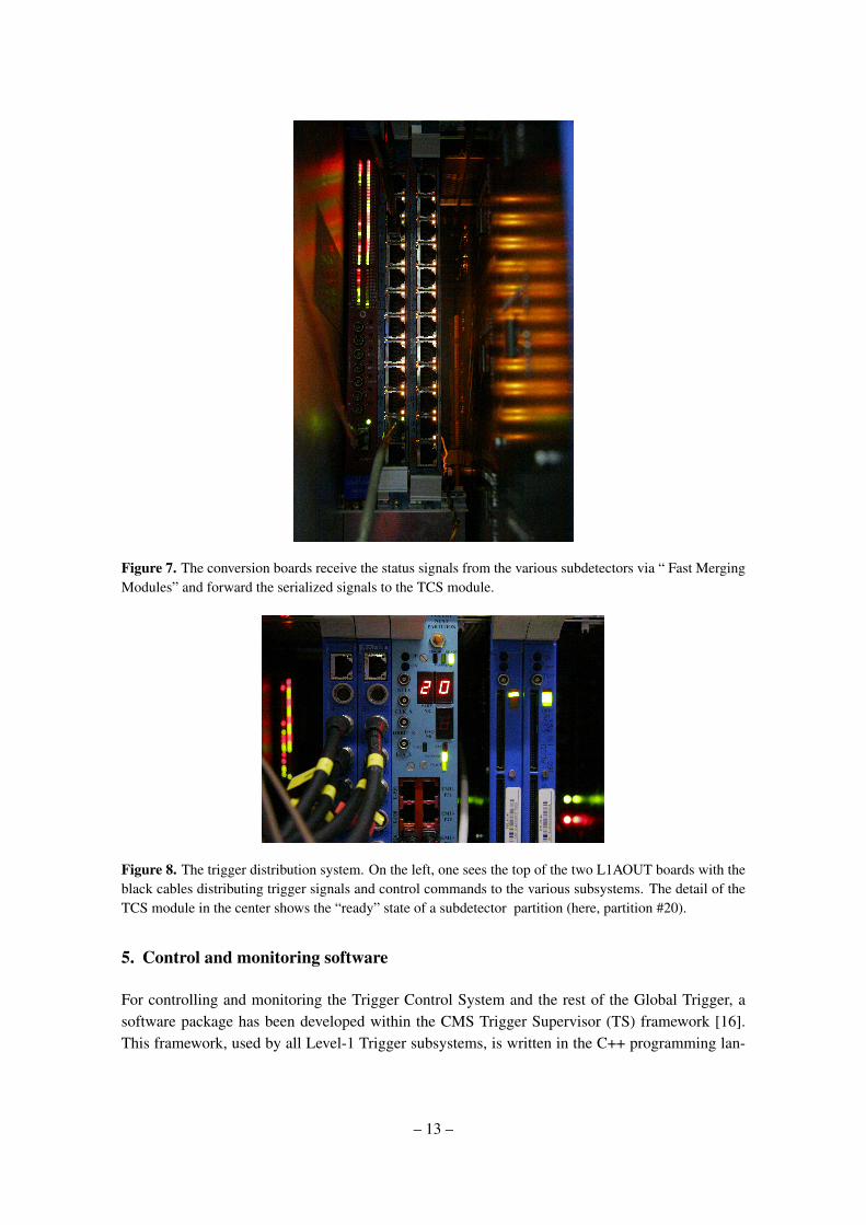
Figure 7. The conversion boards receive the status signals from the various subdetectors via “ Fast MergingModules” and forward the serialized signals to the TCS module.
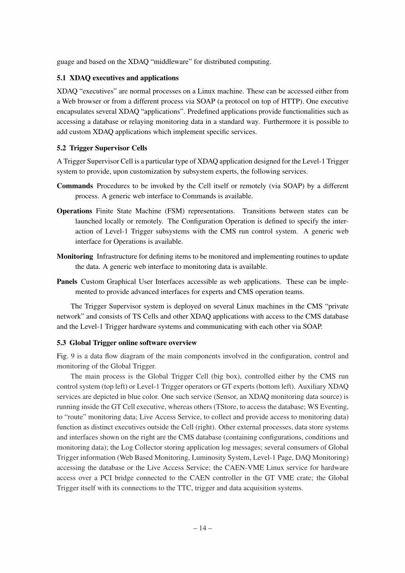
Figure 8. The trigger distribution system. On the left, one sees the top of the two L1AOUT boards with theblack cables distributing trigger signals and control commands to the various subsystems. The detail of theTCS module in the center shows the “ready” state of a subdetector partition (here, partition #20).
5. Control and monitoring software
For controlling and monitoring the Trigger Control System and the rest of the Global Trigger, asoftware package has been developed within the CMS Trigger Supervisor (TS) framework [16].This framework, used by all Level-1 Trigger subsystems, is written in the C++ programming lan-
– 13 –
guage and based on the XDAQ “middleware” for distributed computing.
5.1 XDAQ executives and applications
XDAQ “executives” are normal processes on a Linux machine. These can be accessed either froma Web browser or from a different process via SOAP (a protocol on top of HTTP). One executiveencapsulates several XDAQ “applications”. Predefined applications provide functionalities such asaccessing a database or relaying monitoring data in a standard way. Furthermore it is possible toadd custom XDAQ applications which implement specific services.
5.2 Trigger Supervisor Cells
A Trigger Supervisor Cell is a particular type of XDAQ application designed for the Level-1 Triggersystem to provide, upon customization by subsystem experts, the following services.
Commands Procedures to be invoked by the Cell itself or remotely (via SOAP) by a differentprocess. A generic web interface to Commands is available.
Operations Finite State Machine (FSM) representations. Transitions between states can belaunched locally or remotely. The Configuration Operation is defined to specify the inter-action of Level-1 Trigger subsystems with the CMS run control system. A generic webinterface for Operations is available.
Monitoring Infrastructure for defining items to be monitored and implementing routines to updatethe data. A generic web interface to monitoring data is available.
Panels Custom Graphical User Interfaces accessible as web applications. These can be imple-mented to provide advanced interfaces for experts and CMS operation teams.
The Trigger Supervisor system is deployed on several Linux machines in the CMS “privatenetwork” and consists of TS Cells and other XDAQ applications with access to the CMS databaseand the Level-1 Trigger hardware systems and communicating with each other via SOAP.
5.3 Global Trigger online software overview
Fig. 9 is a data flow diagram of the main components involved in the configuration, control andmonitoring of the Global Trigger.
The main process is the Global Trigger Cell (big box), controlled either by the CMS runcontrol system (top left) or Level-1 Trigger operators or GT experts (bottom left). Auxiliary XDAQservices are depicted in blue color. One such service (Sensor, an XDAQ monitoring data source) isrunning inside the GT Cell executive, whereas others (TStore, to access the database; WS Eventing,to “route” monitoring data; Live Access Service, to collect and provide access to monitoring data)function as distinct executives outside the Cell (right). Other external processes, data store systemsand interfaces shown on the right are the CMS database (containing configurations, conditions andmonitoring data); the Log Collector storing application log messages; several consumers of GlobalTrigger information (Web Based Monitoring, Luminosity System, Level-1 Page, DAQ Monitoring)accessing the database or the Live Access Service; the CAEN-VME Linux service for hardwareaccess over a PCI bridge connected to the CAEN controller in the GT VME crate; the GlobalTrigger itself with its connections to the TTC, trigger and data acquisition systems.
– 14 –

DB storarge
configuration and control services
Web Based Monitoring Services
Central Cell
Live Access Serviceaccess to mon. data
CMS DatabaseTStorerelay DB commands
Run Control
WS Eventing Service• notifiy subscribers• access to mon. data
Global Trigger
DAQ-PTC0TCS
operations & commands
config state buffer
periodic monitoring
general mon. buffer
config data cache
update GT HW status details
config data
current config state
Sensorcollect & relay monitoring data
T = 30 s
T = 5 s update live trigger counters
GT HW mon. buffer
partitions mon. bufferT = 1 s update partitions FMM status
LS mon. bufferupdate dead time and trigger counters for expired LST = LS
DB job queue
process nextDB job
configuration data
monitoringdata
HW Function Manager taskGT r/w access
CAEN-VMErelay VME cmds via PCI bridge
VME cmd.
automatic resynchronization and reset signals to partitions
partitionsstatus
luminosity segment (LS) number
conditions data
Global Trigger Cell
T = 0.5 s
web applications (GUIs)
Log Collectorerrors, warnings
DAQ/HLT
L1 Trigger
TTC/LHC
other L1 Trigger subsystem Cells
GT Expert
L1 Page Services
Luminosity System
DAQ Monitoring
monitor GT & partitions (8 DAQ, 32 TTC)
configure and control GT
monitor trigger and dead time counters
define main GT trigger setup, store in DB
inspect/create/validate setups in GT or DB
detailed status monitoring of GT modules
DAQ Shifter
Trigger Shifter
Web Browser
Trigger Supervisor application
SOAP message
XDAQ application
data flow
Legend:
Figure 9. Data Flow Diagram of the Global Trigger and Trigger Control System online software and externalcomponents.
5.4 Configuration and control services
Prior to every unit of data taking CMS configures all its systems. The Global Trigger configurationprocess is handled by the GT Cell configuration service. Several database record identifiers areforwarded by the run control system to define the setup. The following steps are performed toconfigure the Trigger Control System.
• Initially a cold-reset procedure is automatically executed if the TCS chips are found to be inan uninitialized state (for instance after a power cut). In this case firmware is flashed ontothe chips from PROM memories.
• Setup parameters are downloaded from the database (or retrieved from a local cache) andapplied to the TCS. In particular, the firmware version is checked; the partitioning of the datataking into several DAQ partitions is defined; the eight DAQ-PTCs are set up; automatic orperiodic resynchronizing or resetting of the detector by software is configured.
• TCS trigger sources (physics, random, calibration) are selected.
• The FMM status signals of CMS partitions not participating in the data taking are flagged tobe ignored.
When a run starts the applied setup is recorded in the database. On “Start” due trigger sourcesare enabled; on “Pause” they are temporarily disabled; on “Resume” they are re-enabled; on “Stop”they are disabled. These transitions can be executed for the eight DAQ partitions independently ofeach other. A stopped DAQ-PTC can be reconfigured without disturbing other running DAQ-PTCs.(This feature is currently not integrated with the CMS run control system.)
– 15 –
5.5 Monitoring services
The hardware status and trigger conditions of the Global Trigger are monitored continuously. Per-sistent storage of monitoring data in the database is adopted for the most important quantities.Monitoring of the TCS comprises the following items:
• every 30 seconds: TCS status flags, Finite State Machine states of DAQ-PTCs etc.;
• every second: Status of 32 connected detector partitions (this information is used to automat-ically resynchronize the detector if this is configured), eight DAQ partitions, Global Trigger;
• every 5 seconds: number of sent triggers, event number, LHC orbit number;
• every luminosity segment: number of incoming and lost candidate Level-1 Accepts, num-ber of generated Level-1 Accepts for each type (physics, random, calibration), dead timecounters.
These periodic monitoring data as well as general information about the configuration stateare forwarded to the XDAQ monitoring infrastructure for live access by several consumers such asthe Web Based Monitoring, which is an essential resource for physics analysis, or the LuminositySystem, which provides important input for the interpretation of physics data by calculating therecorded luminosity from the delivered luminosity by correcting for the deadtime measured by theTCS.
5.6 Graphical User Interfaces
Specialized Graphical User Interfaces have been designed to provide monitoring and control toolsfor shifters and Global Trigger experts and to allow maintenance of the hardware setups in thedatabase. Each panel is briefly described in the following with regard to its functionality for theTrigger Control System.
Partitioning panel Monitor the status of the GT and the partitions and their assignment to theDAQ partitions; turn on or off ignoring backpressure from partitions via FMM signals; assigntime slots to each DAQ partition.
Configuration panel Toggle on or off trigger sources; set the random trigger frequency; sendresynchronization of reset commands to a DAQ partition; switch on or off sending of signalsto partitions; apply predefined setup (identified by a GT Key) to the whole Global Trigger;apply predefined setup (identified by a GT Partition Key) to the functions related to a singleDAQ partition.
Trigger Monitor panel Monitor trigger number, event number, luminosity segment number;monitor all trigger and deadtime counters; access data for most recent luminosity segments.See Fig. 10.
Run Settings panel Define Run Settings (including selection of TCS trigger sources) and storethem as a GT Run Settings Key; display settings applied for passed runs.
– 16 –

Configuration Editor Browse, create, compare and validate database setups for any Level-1 sys-tem (including GT and TCS); compare database settings to applied hardware settings; edithardware settings directly. This is a versatile application originally developed for the GlobalTrigger and later used by all Level-1 subsystems.
Hardware Monitor Access the three most recent samples of all hardware monitoring items.
Figure 10. One panel of the control software displayed in a Web browser. The panel displays the values ofthe various monitoring counters for the last few luminosity sections.
6. Performance and results
The Global Trigger and the Trigger Control System were already used for a number of years beforethe LHC startup during the integration of the CMS detector and electronics and for numerousdetector tests with cosmic particles. They have been operating continuously in production modesince the first collisions of LHC beams. Over this period a number of additional requests have beenmade by the various subsystems interacting with the Global Trigger, and they have been taken intoaccount in updates of the firmware of the Trigger Control System and other modules of the GlobalTrigger. On the software side, improvements based on running experience were implemented inorder to maximize the usability of the central trigger control system. The system has proven to behighly reliable and at the same time flexible. All design objectives have been reached. In particular,it has been shown that the system runs stably at a rate of 100 kHz, which is the design value of theCMS Level-1trigger.
Acknowledgments
The authors gratefully acknowledge support from many members of the CMS Trigger group. Theyalso wish to thank the CERN TTC group, especially Jan Troska and André Holzner, for their
– 17 –

assistance during tests and integration of the central TCS into the CMS environment, as well asthe data acquisition group (in particular, Christoph Schwick) for their support in integrating thetrigger and readout systems. Jeroen Hegeman and André Holzner have reviewed the manuscript,and Michael Hoch has produced the photographs for this paper. Support from the Austrian FederalMinistry of Science and Research is gratefully acknowledged.
References
[1] C.-E. Wulz, Concept of the CMS First Level Global Trigger for the CMS Experiment at LHC, Nucl.Instr. Meth. A473/3 (2001) 231-242.
[2] A. Taurok et al., Implementation and Synchronisation of the First Level Global Trigger for the CMSExperiment at LHC, Nucl. Instr. Meth. A473/3 (2001) 243-259.
[3] M. Jeitler et al., The Level-1 Global Trigger for the CMS Experiment, in the proceedings of The 12thWorkshop on Electronics for LHC Experiments, 23-27, Sep. 2006, Valencia, Spain, 2006, JINST 2P01006.
[4] CMS Collaboration, The TriDAS Project – The Level-1 Trigger Technical Design Report,CERN/LHCC 2000-38 (2000).
[5] CMS Collaboration, The TriDAS Project – Data Acquisition and High-Level Trigger Technical DesignReport, CERN/LHCC 2002-26 (2002).
[6] A. Racz, R. McLaren, E. Van der Bij, The S-LINK 64 bit extension specification : S-LINK 64, CERN,Geneva (2003).
[7] H. Sakulin, Design and Simulation of the First Level Global Muon Trigger for the CMS Experiment atCERN, Ph.D. thesis defended at the Technical University of Vienna (2002, unpublished).
[8] H. Sakulin and A. Taurok, Implementation and Test of the First-Level Global Muon Trigger of theCMS Experiment, proceedings of the 11th Workshop on Electronics for LHC and Future Experiments,12-16 Sep 2005, Heidelberg, Germany; CERN-LHCC-2005-038 pp. 279-283.
[9] The CMS Trigger and Data Acquisition Group, editor: J. Varela, CMS L1 Trigger Control System,CERN CMS-Note 2002-033 (2002).
[10] B. G. Taylor, Timing Distribution at the LHC, proceedings of the 8th Workshop on Electronics forLHC and Future Experiments, 9-13 Sep. 2002, Colmar, France.
[11] J. Troska et al., Implementation of the timing, trigger and control system of the CMS experiment,IEEE Transactions on Nuclear Science, vol.53, no.3 (2006) 834-837.
[12] S. Baron, "Status of the TTC upgrade", TWEPP 2006; CERN-LHCC-2007-006, pp.236-240.
[13] M. Jeitler et al., The Central Trigger Control System of the CMS experiment at CERN, proceedings ofthe 11th Pisa Meeting on Advanced Detectors, Nucl. Inst. and Meth. in Phys. Res. A 617 (2010)332-334.
[14] H. Sakulin et al., The Terabit/s Super-Fragment Builder and Trigger Throttling System for theCompact Muon Solenoid Experiment at CERN, IEEE Transactions on Nuclear Science, vol. 55 (2008)190-197.
[15] Datasheet "DS90CR287/DS90CR288A +3.3V Rising Edge Data Strobe LVDS 28-Bit ChannelLink-85 MHz", May 2002, National Semiconductor Corporation.
[16] I. Magrans de Abril, C.-E. Wulz and J. Varela, Conceptual Design of the CMS Trigger Supervisor,IEEE Trans. Nucl. Sci. 53 (2006) 474-483.
– 18 –