the concept and design of pleated pneumatic artificial...
TRANSCRIPT

THE CONCEPT AND DESIGN OF PLEATED PNEUMATIC ARTIFICIAL MUSCLES
Frank Daerden, Dirk Lefeber
Vrije Universiteit Brussel, Dept. of Mechanical Engineering, Multibody Mechanics Research Group, Pleinlaan 2, 1050 Brussel, [email protected]
Abstract
This paper describes the design of a new type of Pneumatic Artificial Muscle (PAM), namely the Pleated PneumaticArtificial Muscle (PPAM). It was developed as an improvement with regard to existing types of PAM, e.g. the McKib-ben muscle. Its principle characteristic is its pleated membrane. It can inflate without material stretching and frictionand has practically no stress in the direction perpendicular to its axis of symmetry. Besides these it is extremely strongand yet very lightweight and it has a large stroke compared to other designs. A general introduction on PAMs is giventogether with a short discussion and motivation for this new design. The concept of the PPAM is explained and amathematical model is derived. This model proves its principle of operation. From the model, several characteristics,such as developed force, maximum contraction, diameter, volume and membrane tensile stress, are obtained. Materialchoices and dimensions of a typical PPAM are next discussed and its measured values of static force and diameter arecompared to the model predicted values. The agreement between both is found to be very good.
Keywords: pleated pneumatic artificial muscle, PAM, PPAM, McKibben muscle, pneumatic, actuator, lightweight, compliance.
1 Introduction
Pneumatic Artificial Muscles (PAMs) are contrac-tile and linear motion engines operated by gas pressure.Their concept is very simple: the actuator’s core ele-ment is a flexible reinforced closed membrane attachedat both ends to fittings along which mechanical poweris transferred to a load. As the membrane is inflated orgas is sucked out of it, it bulges outward or is squeezed,respectively. Together with this radial expansion orcontraction, the shell contracts axially and therebyexerts a pulling force on its load. The force and motionthus generated by this type of actuator are linear andunidirectional. This contractile operation distinguishesthe PAM from bellows, which extend upon inflation.Although it is possible to design an underpressure op-�������� �� ��� ����������� ������� �������������� ���Palko (1993), PAMs usually operate at an overpressuresince a lot more energy can be conveyed that way.
Assuming quasi-static conditions and neglectingenergy losses and the energy needed to deform themembrane, the generated force can be put as
cdl
dVpF −= (1)
where p is the pressure difference with regard to the
surroundings (gauge pressure), V the enclosed mem-brane volume and cl the muscle contracted length, cf.
Fig. 1. In reality however, energy losses and deforma-tion energy cannot usually be disregarded and the de-veloped force will have a lower value. Nevertheless,Eq. 1 shows how the generated force depends on theapplied gauge pressure and on the change of volumewith regard to length—which is characteristic of thetype of membrane used. The state of a particular kindof PAM is thus fully determined by its length andgauge pressure.
PAMs are extremely lightweight actuators becausebasically they are no more than a membrane. Power toweight ratios in excess of 1 kW/kg are reported, seeCaldwell et al. (1995), Hannaford et al. (1995) andDaerden (1999). Besides this, PAMs are characterisedby their compliance which is due not only to gas com-pressibility but also to the varying force to displace-ment. Therefore, compliance can easily be adjusted andcontrolled, Daerden et al. (1999). These actuators canalso be directly connected to a robotic joint because oftheir high output forces at all speeds. No gears have tobe used and therefore no inertia or backlash is intro-duced. Moreover, PAMs are easy to connect and do notbring about hazards like fire, explosion, electric shock

- 2 -
or pollution.Ever since their first conceiving, which the authors
could trace back to a patent by Sensaud de Lavaud(1929), fluid–driven muscle–like actuators of a numberof kinds have been developed. Most of these wereeither too complex or too unreliable to be practicable,e.g. the designs by Baldwin, Kukolj, Yarlott, Paynter,���������� ���� � ��������������� �������� �������Braided muscles, also called McKibben muscles, aremost commonly used to date. This is probably becauseof their simple design and assembly: they are composedof a gas–tight elastic tube or bladder surrounded by adouble helically braided sleeve. When pressurised thetube presses laterally against the sleeve. By changingits braid angle the braid changes its length, diameterand volume. According to Baldwin (1969),J. L. McKibben introduced this type of PAM as anorthotic actuator in the late 1950’s: due to the similarityin length–load curves between this artificial muscle andskeletal muscle, it seemed an ideal choice for this pur-pose, as stated by Schulte (1961). However, practicalproblems such as pneumatic power storage or avail-ability and poor quality valve technology at that time,gradually reduced interest from the prosthesis/orthoticscommunity in McKibben’s muscles. In the late 1980’sit was reintroduced by Bridgestone Co. in Japan as theRubbertuator, Inoue (1987), and used to power an in-dustrial use robot arm, Soft Arm. Recently, a variant onthe McKibben design by the name of MAS was de-signed and marketed by Festo AG. Several researchgroups use PAMs to power robots—mainly of anthro-pomorphic design—and prostheses and orthotics, e.g.Greenhill (1993), Hesselroth et al. (1994), Hannaford etal. (1995), Winters (1995), Noritsugu and Tanaka(1997), Tondu (1997), Caldwell et al. (1998) and Ver-relst et al. (2000).
In spite of its widespread use, the braided musclehas important drawbacks as will be seen further. Thispaper presents a new design of PAM by Daerden(1999), namely the Pleated PAM (PPAM). It will beshown that this designs is an improvement compared tothe braided muscle with regard to several actuator char-acteristics.
2 Pleated PAM
2.1 Goal
The Pleated PAM was developed because of severalweak points of the braided muscles. Firstly, due to dryfriction between the braid and the tube these actuatorshave substantial hysteresis, see Chou and Hannaford(1996) and Tondu et al. (1995). This has an adverseeffect on actuator behaviour and necessitates the use ofcomplex actuator models and control, e.g. Tondu(1997) and Caldwell et al. (1995). Secondly, deforma-tion of the rubber tube lowers the generated force be-cause of the energy it requires. This effect depends offcourse on the toughness of the rubber used, the tougherthe rubber, the stronger the effect. Thirdly, the appliedpressure has to exceed a threshold value to start the
expansion of the tube. This value also depends on thetoughness of the rubber, a value of about 100 kPa fortypical McKibben Muscles is cited by Chou and Han-naford (1996). A fourth weak point, also related to themembrane material, is failure. Klute and Hannaford(1998) describe rubber fatigue failure as the mostcommon failure mode. Many users also complain ofwires snapping at the end point of the actuator, i.e.where the tube and netting are clamped together. Inaddition to the above cited drawbacks, the displacementcapability of braided muscles is rather limited. Totaldisplacement or stroke, which is usually expressed as apercentage with regard to a reference length, rangesbetween 20% to 30% of the length at rest, see Chou andHannaford (1996), Inoue (1987) and Tondu et al.(1995).
Other types of PAM have some improvements withregard to these points but often introduce other disad-vantages. ROMAC muscles for instance, Immega(1986), can generate very high forces and are not both-ered by friction and material deformation. Contractioncan be up to 50% of the initial length. Their majordrawback, however, is their complex shape, makingthem difficult to construct. On top of this, ROMACsare netted muscles, i.e. they consist of a membraneencompassed by a netting, and are therefore character-ised by strong stress concentrations in the surroundingwires and, hence, early material failure.
Thus, the improved PAM design that was lookedfor had to show: (1) low membrane material deforma-tion, (2) no, or at least very low friction/hysteresis,(3) high tensile strength in the longitudinal direction,(4) uniform membrane loading, (5) low threshold pres-sure, (6) high maximum pressure and (7) high maxi-mum contraction.
2.2 Concept
From the discussion above, it is clear that materialdeformation should be avoided. This can be done byusing membrane rearranging in order to allow for in-flation. The principle of rearranging is to have a mem-brane that in some way unfurls as it is inflated. Whensuch PAMs contract their membranes’ surface area donot change contrary to the increasing surface area ofdeforming membranes.
The basic idea of the PPAM was to do this by usinga cylindrical membrane of a high tensile stiffness andhigh flexibility and folding it together along its centralaxis, like accordion bellows. The membrane materialneeded to expand is thus stashed away inside the folds.At both ends the membrane is tightly locked to fittings,which also carry the gas inlet and outlet ducts. Whensuch a PAM is pressurised it shortens and bulges. Asthe membrane has a high tensile stiffness, the expan-sion is highest in the middle of the membrane andgradually goes down toward both ends where no ex-pansion at all can occur. Inflation therefore happens byunfolding, as is shown in Fig. 1. Because the fold facesare laid out radially no friction is involved in this proc-ess and no friction related hysteresis will occur. Fur-thermore, unfolding needs no appreciable amount ofenergy so no loss of output force will ensue from this.

- 3 -
Fig. 1: Pleated PAM, (a) uninflated, at rest and(b) inflated.
Ideally, such a PAM would have an infinite amountof infinitely narrow pleats, leading to an axisymmetri-cal membrane surface that would thus only be loadedby meridional stresses (i.e. along fold lines) and not byparallel stresses (i.e. along parallels, which are sectionsof the surface and any plane perpendicular to the axisof symmetry). This can be seen as follows. If any par-allel stress would exist in such a membrane at someequilibrium contraction, it would unfold the membranefurther, since folds cannot withstand tensile stress. As aresult of this, the membrane diameter would have toincrease, which, at a fixed contraction, can only happenby stretching in the meridional direction. The hightensile stiffness of the material makes it nearly un-stretchable though and, therefore, unfolding can onlyhappen if the membrane contracts further. An idealPPAM, consequently, cannot have parallel stress com-ponents. Its lateral expansion can happen unhamperedand at no energy cost.
2.2 Mathematical model
The ideal pleated PAM can mathematically be de-scribed by an orthotropic membrane that is closed,flexible, axisymmetrical and subjected to an axial forceF at both ends and to a uniform orthogonal surfaceload p , which is the pressure difference across the
surface. This orthotropic membrane has a zero modulusof Young in the parallel direction but not in the meridi-onal direction. This amounts to a zero parallel stresscondition and actually states that the external loads arebalanced by meridional membrane stress only. As in-flation is done by unfurling the infinitely small foldsthe membrane parallel cross section area, i.e. sheetthickness times circumference, never changes. It hasthe same value at any parallel section and is unaffectedby the state of inflation.
The surface of this membrane is generated by a me-ridian curve that is revolved about the axis of symme-try, the x -axis. From a static force equilibrium analysis
of the membrane, a relation between the shape of thegenerating curve, the membrane meridional tensilestress σ , the applied gauge pressure p and the devel-
oped force F can be established, see Daerden (1999).Because of axisymmetry, two force equilibrium equa-tions are obtained:
2
2
1
2
r
srFpr
′+=+ πσπ (2)
( ) 0=′srσ (3)
where r represents the meridian’s distance to the x -axis, s the sheet thickness and the derivative is withrespect to x .
In order to solve it, it is completed by two equationsexpressing linear elastic material behaviour in the me-ridional direction and the constant parallel membranecross section area A :
ldx
E
rcl
=+
′+∫2/
0
2
1
12
σ(4)
Ars =π2 (5)with 0=x at the membrane centre. The boundaryconditions for this set are Rlr c =)2/( , which is the
membrane uninflated radius, cf. Fig. 1, and 0)0( =′r .
For every possible value of contraction, which is de-fined as
l
lc−=1ε (6)
with cl and l as in Fig. 1, the set of Eqs. 2 to 5 of the
unknowns r , σ , F and s has to be solved. Thisinvolves the use of elliptic integrals of the first andsecond kind, which are defined as
∫−
=ϕ
θ
θϕ0
2sin1)\F(
m
dm (7)
∫−
=ϕ
θ
θϕ0
2sin1)\E(
m
dm (8)
respectively.
2.3 Characteristics
The meridian curve or )(xr is given by a paramet-
ric representation )()( ϕϕ rx − :
−= )\F(
2
1)\E(
cosmm
m
Rx
R
ϕϕϕ
(9)
ϕϕ
coscos R
Rr = (10)
where ϕ runs from zero to some value Rϕ . The con-
stants m and Rϕ are determined from
)1(cos
)\F()\E(2ε
ϕϕϕ
−=−
R
l
m
mm
R
RR (11)
+=
RR
R
m
a
R
l
m
m
ϕϕϕ
2cos21
cos
)\F((12)

- 4 -
In the latter equation a takes into account the elastic
behaviour in the meridional direction: AE��a 2= ,
with E the modulus of Young.Figure 2 shows the meridians for a membrane of
l =10 cm, R =1 cm, and a =10–4 ( A =31.4 mm2,E =10 GPa, p =100 kPa) for various values of con-
traction. As can be seen from the diagram, even at anegative contraction of the membrane, i.e. elongation,it bulges slightly outward due to elasticity. This effectis all the less as the membrane’s tensile stiffness in themeridional direction increases.
Fig 2: Meridians of a zero parallel stress membraneat various contractions.
All other characteristics are expressed as the prod-uct of a dimensionless function and a factor of theappropriate dimensions. These dimensionless functionsare determined by m and Rϕ and thus only depend on
contraction, on Rl , which is called the muscle slen-
derness, and on a as can be seen from Eqs. 11 and 12.As an example the developed pulling force is found tobe
)( ,,2 aR
lfplF ε= (13)
Fig. 3: Dimensionless force function.
The dimensionless force function f is diagrammed in
Fig. 3 for a slenderness of 10 to 1. This shows the ac-tuator force to be a non–linear function of displace-ment. At full length or zero contraction the developedforce is extremely high but as contraction goes on itdrops gradually toward zero. At that point the actuatorhas reached its maximum contraction. The influence of
the membrane’s elasticity can be seen from the dia-gram. At low contractions the developed force is con-siderably lowered because of bulging due to membranestrain. This means that, in practice, the developed forcewill never be infinitely high as would be the case for aninelastic membrane ( ∞=E or 0=a ). As contractiongrows beyond 5% the influence is only moderate. Themaximum contraction is somewhat lowered, which isless discernible on the diagram: stroke is 45.5% for aninelastic membrane and 44.5% when 001.0=a .
Because the effect of elasticity is very small at con-tractions of more than 5% for a high tensile stiffnessmembrane, the value of a can accordingly be set tozero and Eqs. 11 and 12 will then yield m and Rϕ as a
function of contraction and Rl only. With this inelas-
tic approximation, the following expressions werefound for the pulling force, the meridional stress σ ,the membrane central or equatorial diameter D and itsenclosed volume V :
)( ,2
R
lfplF ε= (14)
)( ,2
R
l
A
pl εςσ = (15)
)( ,R
ldlD ε= (16)
)( ,3
R
lvlV ε= (17)
with f , ς , d and v the according dimensionless
functions. These expressions show how membranes ofdifferent sizes but identical slenderness have their char-acteristics scaled with size: central diameter withlength, force with the square of length and volume withthe cube of length. Meridional stress is independent ofsize if the sheet thickness is proportional to size. Forceand stress are also proportional to the applied pressurelevel, as could be expected. If one intends to double theforce at the same pressure while using geometricallysimilar membranes, length has to increase by only 41%,but volume—and thus pressurised gas consumption—will then increase by 183%. However this also impliescontraction lengths being 41% larger, which is notalways needed. On the other hand, if one does not needhigh forces it is possible to replace one long membraneby a series of n similar but shorter ones so that totallength and contraction are preserved but total volume
and force are divided by 2n .Figure 4 shows the inelastic approximation of f as
a function of contraction for various values of mem-brane slenderness. Except for the hypothetical case ofan infinitely thin muscle force will tend to infinity forzero contraction. In reality however, due to elasticitythe force levels will drop at low contractions, whichcould already be seen from Fig. 3. Stubby membranes,i.e. low value of slenderness, are clearly stronger at lowcontractions but their developed force also drops at asteeper pace. This is because in stubby membranes thegas has a much greater surface against which to act butat the same time the end closure surfaces and therebythe pressure load acting against them increase.

- 5 -
Fig. 4: Dimensionless force function.
Fig. 5: Pleated PAM stroke.
Figure 5 plots the actuator stroke as function of theinverse of slenderness. Stroke is strongly dependent onslenderness: slim membranes have a greater stroke thanstubbier ones. As R increases with regard to l, the pres-sure load acting on the end closures increases and thiswill bring F to zero at lower values of ε . An infinitelyslim membrane has the greatest ability to contract witha stroke of about 54.3%. This is a limiting case that willnot be feasible in practice. At a more practicable slen-derness of Rl =10 the maximum contraction is about
45.5%, a membrane having an initial diameter equal toits length, has a total contraction of only 22.3%.
The diagram of Fig. 6 sets the dimensionless func-tion of meridional stress as a function of contraction.From Eqs. 3 and 5, it is clear that the meridional stressis the same throughout the membrane. The level ofstress obviously never drops to zero: a fully inflatedmuscle does not produce any pulling force, but it istense nonetheless.
Figure 7 shows how the central diameter evolveswith contraction. It is clear how the relative expansionis larger for slimmer membranes. This implies thatslimmer PPAMs actually need more folds to be able toexpand fully and are, therefore, more difficult to build.
The value of d at maximum contraction, d ′ , is givenin Fig. 8. This indicates how wide the muscle will getwith regard to its full length, depending on its slender-ness.
Fig. 6: Dimensionless stress function.
Fig. 7: Dimensionless diameter function.
Fig. 8: Maximum values of diameter function.

- 6 -
The evolution of volume with contraction is seen inFig. 9. Although they bulge less, wider membraneshave a higher increase in volume with contraction and,therefore, a higher possible transfer of work. Becauseof this and because they are easier to construct onecould be inclined to favour stubby PPAMs. These havetwo important drawbacks, however. As they have asmall travel and high force, they put higher loads to thestructure they are connected to compared to slimmerones transferring the same work. Secondly, they have alarge dead volume (i.e. at 0=ε ), as can be seen fromthe diagram, and this has to be charged or dischargedwhenever changing the pressure inside the musclealthough it does not contribute to the generation offorce, cf. Eq. 1.
Fig. 9: Dimensionless volume function.
Fig. 10: Circumferential force concentration.
It is interesting to look at the plot of dimensionlessforce per unit length along the end fittings’ circumfer-ence, or Rf π2 , as shown in Fig. 10. Comparing ac-
tuators of the same length, the slimmer ones generateless pulling force but their force to circumference ratioincreases. This implies that slender membranes imposehigher stresses on the end fittings even though forces
are generally lower. Together with the higher amountof folds needed, as stated above, this will put a lowerlimit on technically feasible values of slenderness.
2.4 Goals check
Going over the design goals that were set out in§ 2.1 it can now be seen that they can all be met by theconcept of the pleated PAM and by an adequate choiceof materials. (1) Material deformation can be kept to aminimum by choosing a high tensile stiffness material,e.g para–aramid with a Young’s modulus over100 GPa, and because of the expansion by membranerearranging. (2) Friction and, hence, hysteresis arenearly eliminated by the principle of folding/unfoldingand because no outer braid or netting is used. (3) Hightensile strength in the longitudinal direction is obtainedby choosing the right material. (4) The stress distribu-tion is uniform for an ideal PPAM, as was seen above.Because of the limited amount of pleats non–uniformi-ties will be present though in real pleated PAMs. Thesecan be expected to grow as the amount of pleats de-creases, so putting in as much folds as possible will beimportant. (5) The threshold pressure will be deter-mined by the flexibility of the membrane: pleating asheet is known to increase its structural strength andresistance to deformation—in this case inflation—andthis will be all the more so if the material is only mod-erately flexible. Values of 100 kPa, as is the case forsome braided muscles, are very high compared to whatcan be expected for a pleated PAM , as will be seen inthe next section. (6) The maximum allowable pressurewill, in theory, be set by the tensile strength of thematerial. In practice, extra limiting factors will arise,e.g. stress concentration at the membrane to end fittingattachment. (7) The maximum contraction of this typeof PAM depends on its slenderness: values of around45% are easily obtained. Compared to other kinds ofPAMs this is quite high a value.
3 Practical realisation
The surface of a pleated PAM is not axisymmetricalbecause of the limited amount of pleats. Instead, it hasa rotationally repeated pattern of ridges and valleys—provided all pleats have the same dimensions.Therefore, parallel stress components and a meridionalstress non–uniformity can be expected to exist. In orderto keep these small and approximate the idealmembrane to a good degree, the number of folds oughtto be as high as possible and their depth as small aspossible.
As an example, this section describes a pleatedmuscle of 10=l cm and 25.1=R cm. It has 44 folds,each having a depth of 2.5 mm. With a pleat pitch of7 mm the membrane circumference is 744 × mm, al-lowing the membrane diameter to grow to 9.8 cm.Calculations from the mathematical model presentedabove predict a maximum diameter of 9.54 cm.
For the mechanical design, choices had to be maderegarding the membrane and end fitting materials andregarding their connection method. A Kevlar©49 fabric
- 7 -
was chosen as primary membrane material. Kevlar©49,which is produced by DuPont de Nemours, is a para–aramid polymer. It is spun in filaments of 12 µm diame-ter that are assembled in yarns in various quantities.From these yarns fabrics are woven. Kevlar©49 has ahigh tensile strength ( 4≈ GPa) at a low specific weight(1440 kg/m3), a high elastic modulus ( 130≈ GPa), lowcreep and relaxation, high toughness, good fatigueresistance and non–brittle behaviour. The latter threecharacteristics are important for this application be-cause of the possibly sharp bends at the fold lines, theend fittings and the points of membrane fixing. Thefabric was sealed by a polypropylene lining which wasglued to the fabric by a rubber resin adhesive. Theresulting lining thickness is 0.08 mm and the total sheetthickness 0.28 mm.
Fig. 11: Pleated PAM end fitting assembly.
Because of the extreme smoothness of the fibres aclamp was rejected as a means of fixing the membraneto the end fittings: in order to get a high enough frictionforce to fix the membrane the clamp pressure has torise beyond the allowable lateral fibre pressure. Abonding method to secure the membrane was thereforeused: inside the end fittings the fabric is embedded inan epoxy resin. The assembly of an end fitting is shownin Fig. 11 in a frontal view and a sideways axial crosssection. It consists of a plug and an outer ring, bothmade of aluminium. The plug has a tapered side and atoothed side to it and is shifted into the ring. The mem-brane is inserted between both parts. The toothed sidekeeps the pleats into place and ensures them to be equi-distant. Securing the fabric to the resin is done at thetapered side. No resin is allowed to enter the slots ofthe plug. As a result of this layout, there is only mar-ginal tilting of the fibres at the spot where they comeout of the resin. This is important because these arelocations of stress concentration. The plug is hollow,which allows for external attachment of the load andinlet/outlet of pressurised air.
Fig. 12: Pleated PAM photograph.
The weights of the parts are 7.3 g for the mem-brane, 12.5 g for the plug, 1.8 g for the resin filling and
11.2 g for the outer ring. The total muscle weight, usingtwo basic plugs is thus 58.3 g. A photograph of a pro-totype PPAM is shown in Fig. 12. One of its end fit-tings has an extended plug that has an air duct to oneside.
4 Measured characteristics
The actuator described in the previous section wastested in a draw bench. The developed force and theequatorial diameter were recorded as a function ofcontraction for various values of gauge pressure. Alltest runs were repeated in order to determine the re-peatability. The isobaric force and diameter diagramswere established and compared to those obtained fromthe mathematical model discussed in § 2.2 and § 2.3.
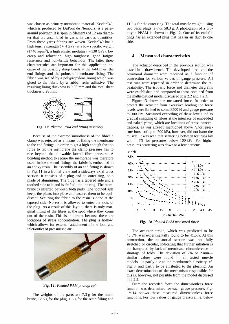
Figure 13 shows the measured force. In order toprotect the actuator from excessive loading the forcelevels were limited to some 3500 N and gauge pressureto 300 kPa. Sustained exceeding of these levels led togradual snapping of fibres at the interface of embeddedand naked yarns, which are locations of stress concen-trations, as was already mentioned above. Short pres-sure bursts of up to 700 kPa, however, did not harm themuscle. It was seen that scattering between test runs laywithin 5% for pressures below 100 kPa. For higherpressures scattering was down to a few percents.
Fig. 13: Pleated PAM measured force.
The actuator stroke, which was predicted to be43.5%, was experimentally found to be 41.5%. At thiscontraction, the equatorial section was not fullystretched or circular, indicating that further inflation isnot hampered by lack of membrane circumference orshortage of folds. The deviation of 2% or 2 mm—similar values were found in all tested musclemodels—is partly due to the membrane’s elasticity, cf.Fig. 3, and partly to be attributed to the pleating. Anexact determination of the mechanism responsible forthis is, however, not possible from the model discussedin § 2.2.
From the recorded force the dimensionless forcefunction was determined for each gauge pressure. Fig-ure 14 shows these measured dimensionless forcefunctions. For low values of gauge pressure, i.e. below

- 8 -
50 kPa, the values of f deviate from those at higher
pressures. This is in disagreement with the mathemati-cal model stating f to be independent of pressure. The
effect gradually decreases as the pressure increases. Asfrom a gauge pressure of 50 kPa the curves are nearlythe same and as from 150 kPa they actually coincide.The deviation is in fact the PPAM threshold pressurebehaviour. As was explained before a pleated mem-brane is less flexible than the flat and unpleated pieceof lined fabric it is made of. A few kPa’s are sufficientto inflate and operate the PAM but not to fully stretchand bulge its surface. This can be visually observed: atlow pressures the membrane yarns are clearly non–uniformly stressed, some regions even remain slack tosome degree and this gives its surface a rough anddented appearance, at higher pressures, the membraneis more strongly forced outward, which makes it taut atevery point and gives it a smooth and very tense ap-pearance. It can be concluded that a single thresholdpressure is difficult to distinct, a value of 10 kPa couldhowever be agreed upon as threshold value. The oper-ating pressures thus range from 10 kPa to 300 kPa orover a ratio of 30. For braided muscles this ratio isabout 6 to 8 as can be concluded from Chou and Han-naford (1996).
Fig. 14: Pleated Pam measured values of f.
Figure 15 plots the measured values of f averaged
for all tests at pressure levels above 100 kPa. Withinthe contraction range of 3% to 30% they match verywell with the calculated values. At lower contractions,the membrane tensile compliance lowers the developedforce to finite values, as was predicted by the model, cf.Fig. 3. At higher contractions, force drops to zero at aslightly steeper pace than predicted by the inelasticmodel. As explained above, this is partly due to theelastic behaviour and partly to the finite value of pleatdepth.
Figure 16 diagrams the values of the measured andcalculated dimensionless diameter function d . Onlythe values at gauge pressures of 50 kPa and 300 kPa areshown because the change in diameter is too small tobe discernible on this scale. The agreement betweencalculated and measured values is very good. The ef-fect of pressure is clearly noticeable at low contrac-
tions, as was predicted by the zero parallel stressmodel. Except for very low pressures scattering be-tween test runs was too low to be of any importance.
Fig. 15: Pleated Pam measured values of f, mean val-ues.
Fig. 16: Pleated PAM measured values of d.
These and other similar tests validated the mathe-matical model proposed in § 2.2 for the pleated PAM.Furthermore, the inelastic model can effectively beused to describe the pleated actuator characteristicswithin the major part of its operating range of contrac-tion. Slight deviations between inelastic model pre-dicted and measured values do occur at extreme condi-tions, i.e. small and high contractions and low pres-sures, but these are not of great practical importance innormal operating conditions. In summary, the PPAMwas found to be a reliable actuation device with a gooddegree of repeatability and predictability.
5 Conclusions
This paper described a new kind of pneumatic arti-ficial muscle, namely the pleated PAM. The purpose ofhaving a new design was explained together with itsconcept. A mathematical model was established andproved to be very accurate with regard to the real

- 9 -
PPAM. The PPAM is very strong compared to otherdesigns, has a larger stroke and is not bothered by fric-tion related hysteresis. It is also extremely lightweight,a PPAM of less than 60 g was seen able to pull 3500 N.
A PPAM is an ideal actuator whenever weight andcompliance are important considerations. Examples ofthis are grippers with an adjustable firmness, strong butlightweight flexible robot arms and walking/runningmachines. Furthermore, PPAMS are easy to control,Daerden et al. (1999), and with them a very accuratepositioning can be obtained, making them also suitablefor this purpose. PPAMs can guarantee a safe man–machine interaction because of the delicate touch theycan effect. This is important e.g. for handling fragile ob-jects or to power rehabilitation devices, to name buttwo.
In summary, PPAMs have several characteristicsthat are not inherent to other, more classical drives, andare an improvement over existing PAMs. Therefore,the authors feel PPAMs are very suitable for a range ofrobotic and automation applications.
References
Baldwin, H. A. 1969. Realizable models of musclefunction. Biomechanics, Proceedings of the FirstRock Biomechanics Symposium, pp. 139–148,Plenum Press, New York.
Caldwell, D. G., Tsagarakis, N., Badihi, D. andMedrano-Cerda, G. A. 1998. Pneumatic muscleactuator technology: a lightweight power system fora humanoid robot. IEEE International Conferenceon Robotics and Automation, pp. 3035–3058,Leuven, Belgium.
Caldwell, D. G., Medrano-Cerda, G. A. andGoodwin, M. J. 1995. Control of pneumaticmuscle actuators. IEEE Control Systems Magazine,Vol. 15(1), pp. 40–48.
Chou C.-P. and Hannaford, B. 1996. Measurementand modeling of McKibben pneumatic artificialmuscles. IEEE Transactions on Robotics andAutomation, Vol. 12(1), pp. 90–102.
Daerden, F. 1999. Conception and Realization ofPleated Pneumatic Artificial Muscles and their Useas Compliant Actuation Elements. PhD thesis. VrijeUniversiteit Brussel, Belgium.
Daerden, F., Verrelst, B., Lefeber, D. and Kool, P.1999. Controlling motion and compliance withfolded pneumatic artificial muscles. Proceedings ofCLAWAR ’99: International Workshop andConference, pp. 667–677, Portsmouth, UK.
Greenhill, S. 1993 The digit muscle. Industrial Robot,Vol. 20(5), pp. 29–30.
Hannaford, B., Winters, J. M., Chou, C.-P. andMarbot, P. H. 1995. The anthroform bioroboticarm: a system for the study of spinal circuits. InAnnals of Biomedical Enineering, Vol. 23, pp. 399–408.
Hesselroth, T., Sarkar, K., van der Smaght, P. andSchulten, K. 1994. Neural network control of apneumatic robot arm. IEEE Transactions onSystems, Man and Cybernatics, Vol. 24(1), pp. 28–38.
Immega, G. B. 1986. ROMAC muscle powered robots.MS86–777, Society of Manufacturing Engineers,Dearborn.
Inoue, K. 1987. Rubbertuators and applications forrobotics. 4th International Symposium on RoboticsResearch, pp. 57–63.
Klute, G. and Hannaford, B. 1998. Fatiguecharacteristics of McKibben artificial muscleactuators. Proceedings of IROS 1998, pp. 1776–1782, Victoria, B.C., Canada.
���������� J. and Palko, A. 1993. Negative pressureartificial muscle—An unconventional drive ofrobotic and handling systems. Transactions of theUniversity of Košice, pp. 350–354, RiecanskyScience Publishing Co, Slovak Republic.
Morin, A. H. 1953. Elastic Diaphragm. US Patent No.2,642,091.
Noritsugu, T. and Tanaka, T. 1997. Application ofrubber artificial muscle manipulator as arehabilitation robot. IEEE/ASME Transactions onMechatronics, Vol. 2(4), pp. 259–267.
Schulte, H. F. 1961. The characteristics of theMcKibben artificial muscle. The application ofexternal power in prosthetics and orthotics, pp. 94–115, Publication 874 of the National Academy ofSciences–National Research Council, LakeArrowhead.
Sensaud de Lavaud, D. 1929. Vorrichtung zurErzeugung eines Über- oder Unterdruckes in Gasenoder Flüssigkeiten. Deutsches PatentschriftNr. 503775.
Tondu, B. 1997. Analysis and modeling of thedynamic behaviour of the McKibben artificialmuscle. Reprints of the 5th IFAC Symposium onRobot Control, pp. 315–319, Nantes, France.
Tondu, B., Boitier, V. and Lopez, P. 1995. Théoried’un muscle artificiel pneumatique et application àla modelisation du muscle artificiel de McKibben.Comptes Rendus de l’Académie des Sciences, Tome320, Série IIb, pp. 105–114, Académie desSciences, Paris.
Verrelst, B., Daerden, F., Lefeber, D., Van Ham, R.and Fabri, T. 2000. Introducing pleated pneumaticartificial muscles for the actuation of legged robots:a one–dimensional setup. Proceedings of CLAWAR2000: Third International Conference, pp. 583–590,Madrid.
Winters, J. M. 1995. Braided artificial muscles:mechanical properties and future uses inprosthetics/orthotics. RESNA 13th AnnualConference, pp. 173–174, Washington DC.

- 10 -
Frank Daerden (1966)
Study of Mechanical Engineeringat the Vrije Universiteit Brussel. PhDin Applied Sciences, Vrije UniversiteitBrussel, 1999. Research and teachingassistant at the Vrije UniversiteitBrussel, 1991–1999. Doctor-Assistantat the dept. of Mechanical Engineering,Vrije Universiteit Brussel since 1999.
Dirk Lefeber (1956)
Study of Civil Engineering at theVrije Universiteit Brussel. PhD inApplied Sciences, Vrije UniversiteitBrussel, 1986. Professor, chairman ofthe department of Mechanical Engi-neering, head of the Multibody Me-chanics Research Group, Vrije Univer-siteit Brussel.