the control of brushless dc motors
TRANSCRIPT
919
1. IntroductionBLDC motor is a special electric machine. It becomes within class of synchronous motor. The rotor of BLDC motor is constituted permanent magnet. The structure of BLDC motor looks like synchronous machines. BLDC motor is defined the shape of the back-EMF of the synchronous motor. Both BLDC and PMSM (Permanent Magnet Synchronous Motor) have permanent magnets on the rotor, but differ in the flux distributions and back-EMF profiles. The back-EMF is trapezoidal in BLDC motor case and sinusoidal in the PMSM motor case. For that reason, the mathematical model of BLDC motor is non-linear because of analysing of BLDC motor is difficult [1]. Nowadays, brushless DC motors have been preferred more than the other electric motors because of their advantages. Principal advantages; high efficiency, high reliability, less maintenance, silent operation, being easily cooled, long life (no brush and collector erosion) and being easily
controlled. Unfortunately, BLDC motors have disadvantages that have a control system more complexity, expensive system and require position sensors to sensing rotor position. Sensorless control contains higher requirements for control algorithms and more complicated electronics. Sensorless control of BLDC motors can’t achieve high speed and acceleration according to motor control with sensors [2]. These motors have been widely used in a variety of applications in automobile industry (hybrid vehicles), space and computer technology, medical electronic, military areas, industrial automation, robotic applications and household products [2].
2. StructuresBLDC motor is composed of a permanent magnetic rotor and three winding stator coils. Besides, it’s used to operate inverter and driver circuit and controller [4]. Fig.1 illustrates BLDC motor’s structure.
The Control of Brushless DC Motors
H. C. BAYRAKTAR1 H. H. BALIK2
AbstractIn this paper, about brushless DC motors and their structures, working principles, types, control logic and control methods commonly used are given general information. Nowadays, using BLDC motors are increased because of their advantages. For example, simple structure, easy control, small size and high effiency etc. Therefore, BLDC motors and their controls has become increasingly important in recently. The result of this paper, most common control techniques are also discussed.
Keywords: Brushless DC Motor; Control
1 Istanbul Aydin University (IAU) 2 Istanbul Aydin University (IAU)
920
The Control of Brushless DC Motors
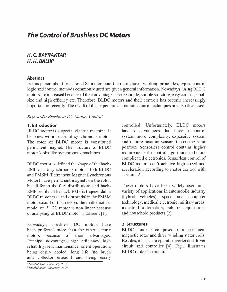
Fig.1. Disassembled view of a brushless dc motor [5].
The construction of brushless dc motor very is very similar to the ac motor. The structure of a typical three-phase brushless dc motor is illustrated Fig.1. Stator is a static part [7]. The number of stator slots is chosen depending on the rotor poles, number of phase and the winding shape. Stator windings can be connected with Y or ∆ configurations as asynchronous motors are connected [8]. The rotor with permanent magnet are used to usually occur one or more permanent magnets in BLDC motors. Rotating part is rotor. The rotor is constructed with permanent magnets because of there is no brush and collector. For that reason no arc, no maintenance and reduced losses of friction. For the rotor is producted, optimum magnetic material is determined. Ferrite magnets are the most popular choices for low-cost motors. But ferrite magnets have low-flux density which is disadvantage [8]. Permanent magnets in rotor are mounted in different forms. Firstly, they can be mounted on the rotor surface. Secondly, they can be mounted in different ways and thirdly, the rotor can be completely occured from permanent magnets [9].
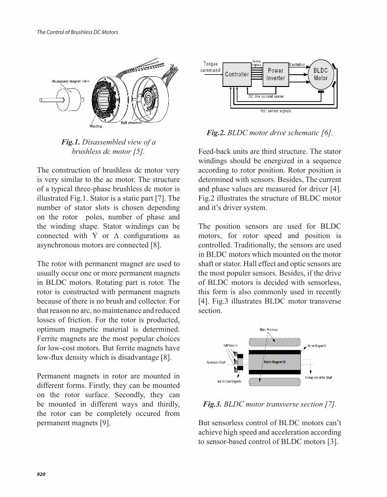
Fig.2. BLDC motor drive schematic [6]. Feed-back units are third structure. The stator windings should be energized in a sequence according to rotor position. Rotor position is determined with sensors. Besides, The current and phase values are measured for driver [4]. Fig.2 illustrates the structure of BLDC motor and it’s driver system. The position sensors are used for BLDC motors, for rotor speed and position is controlled. Traditionally, the sensors are used in BLDC motors which mounted on the motor shaft or stator. Hall effect and optic sensors are the most populer sensors. Besides, if the drive of BLDC motors is decided with sensorless, this form is also commonly used in recently [4]. Fig.3 illustrates BLDC motor transverse section.
Fig.3. BLDC motor transverse section [7]. But sensorless control of BLDC motors can’t achieve high speed and acceleration according to sensor-based control of BLDC motors [3].

921INTERNATIONAL JOURNAL OF ELECTRONICS, MECHANICAL AND MECHATRONICS ENGINEERING Vol.5 Num.2 - 2015 (919-932)
H. C. BAYRAKTAR, H. H. BALIK
Fig.4. The position of Hall Sensors in BLDC motor [10].
Magnetic flux is provided by the rotor permanent magnets for Hall effect sensors. Hall voltage is a small value. It’s 30 mV. Hall voltage is increased by the amplifier [11]. Hall effect sensors are mounted the intervals of 120° or 60° in BLDC motors [10]. Fig. 4 illustrates the shape of Hall sensors in BLDC motor. Optic sensors are also position sensors which provide to measured accurately the rotor position as angular [1]. Optic sensors have two discs. This discs which are stationary and active. Their working principles; can be detected movement as linear or angular and the light is transmitted or not transmitted in two discs from a light source is sent out [12]. Zero crossing dedector is used to know the rotor position according to occur back-EMF on stator windings. This sensor is connected with motor driver. It’s compared to the voltage which superimposed the stator coils and feeding voltage which have semi value. This advantages; this dedectors no movement section and no connected with movement motor section [1].
No sensor studies, Kalman Filter Theory is used as a stronger method. In this method, a mathematical model that contains position, speed and back-EMF values is used. In prediction stage, the change in the motor status at any point in time is predicted by using this method. The predicted back-EMF is compared with measured value and the difference is used for optimizing the motor operation. By using Kalman Method, position and speed of motor can be predicted not only at zero crossings but also at any given time. Therefore more accurate commutation and so higher efficiency can be obtained [13]. Inverter and driver layer is fourth unit. The voltage is obtained for controlling motor in this unit. This unit is inverter system which contains AC/DC inverter, breake resistance, filter and semiconductor switches (For example; transistor, mosfer, IGBT etc.). Controller determines in time which the semiconductor switches remain on or off. This unit occurs from semiconductors which is a switching pattern, is a interval unit [4]. This layer provides to turn of stator windings current to use the rotor position knowledge. Thus, the rotate of rotor is obtained. Controller sents on/off signals who are six semiconductor switches depends on the rotor position knowledge [1]. Fig.5 illustrates switching pattern which is used mosfets.
Fig.5. BLDC motor driver which is used mosfets [14].

922
The Control of Brushless DC Motors
BLDC motor is supplied from a three-phase inverter, and the switching actions can be simply triggered by the use of signals from position sensors that are mounted at appropriate points around the stator. This switching actions performs in proper sequence. Controller provides to switch the driver depends on position sensors knowledge. For one phase positive voltage, for one phase negative voltage is superimposed by the controller. At the same time, the third phase also is not superimposed voltage. This operation is performed systematically which is superimposed respectively for each phase differently. Hence, controller has this driver system configuration which provides obtaining torque. The driver is the most important part which determines the motor performance. Controller and switchs also determine the level of driver performance. For a driver, switches are the most important materials. For the choose of switch, It’s considered to switching speed and losses. Mosfet is commonly used as a switch material. But, It’s also used another semiconductor materials. For example, transistors, thyristor, IGBT etc. IGBT is a semiconductor switching material which operates rapidly than transistors but slowly than mosfets. Mosfets are the best choose for the driver system of BLDC motors have not high power [1]. PWM (Pulse Width Modulation) process is obtaining voltage at different impulse width by switching a fixed source and therefore voltage control at very wide ranges can be optained. Impulse width obtained depends on the total of duration the switch remains on and off, the duration the switch remains on. This is provided by changing the switch off duration or period [1].
Finally, controller is the fifth structure. Using referance entry and position sensor information, controller performs requiring work situations with generating control signals. Control algorithm is determined by the control signals which is generated by the controller. The status of PWM signals is also controlled according to control algorithm. Fundamentally, the speed, current and position rotation is controlled by the controller. Controller is composed of both software and hardware structures [4].
3. Types of BLDC MotorThere are three types of BLDC motors, called inrunner, outrunner and disc type [12]. Besides, There are two types, some BLDC motors have sensors and some BLDC motors have no sensors [15].
3.1. Outrunner MotorsThe stator windings are located in the core of the motor. The rotor magnets surround the stator windings. This type, magnets are embedded in rotor. Stator and rotor structure seems like in brush DC motor’s stucture. This motors have high inertia and are cooled difficult [16]. Fig.6 illustrates outrunner BLDC motor structure.
Fig.6. Outrunner BLDC motor structure [16].
923INTERNATIONAL JOURNAL OF ELECTRONICS, MECHANICAL AND MECHATRONICS ENGINEERING Vol.5 Num.2 - 2015 (919-932)
H. C. BAYRAKTAR, H. H. BALIK
It’s also known outline BLDC motors. Outrunner motors spin slower but output more torque. Hence, they are used for helicopter and plane etc. [15].
3.2 Disc Type BLDC MotorsDisc types brushless DC motors can prefer low power and low speed applications. Fig.7 illustrates disc type BLDC motor structure.
Fig.7. Disc type BLDC motor structure [16]. If we need low speed but high power, we should choose inrunner motor which has high number of poles. If this motor’s speed is more than 1000 rpm, it’s cooled very problem. For that reason, it’s take measures. Thus, the cost is increased [16].
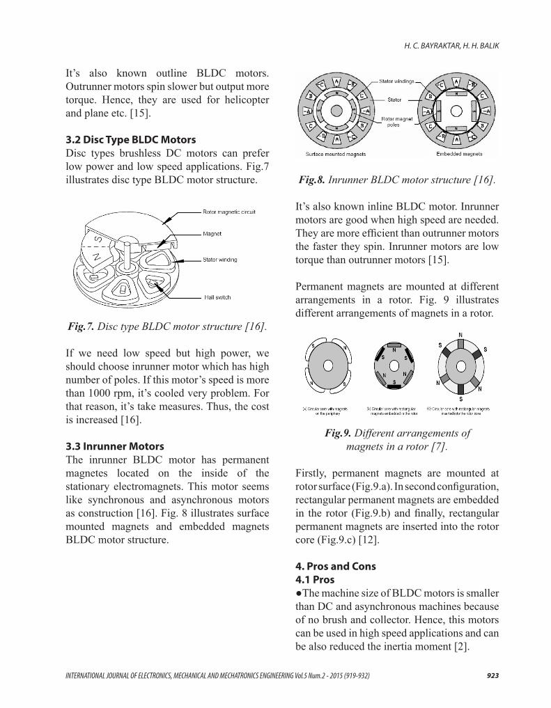
3.3 Inrunner MotorsThe inrunner BLDC motor has permanent magnetes located on the inside of the stationary electromagnets. This motor seems like synchronous and asynchronous motors as construction [16]. Fig. 8 illustrates surface mounted magnets and embedded magnets BLDC motor structure.
Fig.8. Inrunner BLDC motor structure [16].
It’s also known inline BLDC motor. Inrunner motors are good when high speed are needed. They are more efficient than outrunner motors the faster they spin. Inrunner motors are low torque than outrunner motors [15].
Permanent magnets are mounted at different arrangements in a rotor. Fig. 9 illustrates different arrangements of magnets in a rotor.
Fig.9. Different arrangements of magnets in a rotor [7].
Firstly, permanent magnets are mounted at rotor surface (Fig.9.a). In second configuration, rectangular permanent magnets are embedded in the rotor (Fig.9.b) and finally, rectangular permanent magnets are inserted into the rotor core (Fig.9.c) [12].
4. Pros and Cons 4.1 Pros●The machine size of BLDC motors is smaller than DC and asynchronous machines because of no brush and collector. Hence, this motors can be used in high speed applications and can be also reduced the inertia moment [2].

924
The Control of Brushless DC Motors
●The speed control of BLDC motors is very good. The speed range which can be controlled is higher than asynchronous motors [2]. ●BLDC motors required less maintenance than brushed DC motor because of absence of brushes [7].●High efficiency is obtained by BLDC motors [7].●Electric noise generation is lower than brushed DC motor [7].●The life of BLDC motors is long [7].●The operate of BLDC motor is reliable [2].●For operate of BLDC motors, need not exciting current [2].●The torque/volume ratio of BLDC motors is high. Hence, product of BLDC motor is used lower copper [2].●Cooling operation is easy in BLDC motors [2].
4.2 Cons●For the operate of BLDC motors, external power electronic and rotor position information which is desired in operation, requires. Using Hall effect sensors requires in BLDC motor operation [3].●For the sensorless operation of BLDC motors, using additional algorithyms require. This method is more expensive than the others [3].●Inverter errors can occur in BLDC motor’s drivers [16].●The permanent magnet BLDC motors can not reach very high speed. Because, this motors provide stable exciting [16].●If the permanent magnets are used long time, magnetism properties are damaged because of atmospheric and thermic effects [16]. Nowadays, because of technological advanced, using BLDC motor increases and the disadvantages of BLDC motor is reduced [12].
5. Working Principle BLDC motor has stator windings which are fed by inverter. Inverter is also fed by a current source. Inverter consists of power switches. The power switches (semiconductor switches) switch respectively depends on rotor position. The respect of power switches operation is determined by a position dedector in rotor or sensorless control algorithym. Fig. 10 illustrates BLDC motor drive system circuit diagram with position feed-back.
Fig.10. BLDC motor drive system circuit diagram with position feed-back [9].
The direction of current flow is altered in stator windings by using rotor position information. This process is performed by the power switches. This configuration is illustrated by Fig. 5. In this way, the direction of currrent flow and voltage which is superimposed in stator windings, and rotating rotor is provided controlling power switches. Hence, magnetic field poles occur in stator windings. The opposite poles attract each other and the same poles push each other. According to this principle, magnetic field poles in stator and rotor interact each other. For that reason, the torque occurs. The values of torque depends on stator and rotor magnetic field strength. The rotor position alters due to rotating rotor. The new position is dedected by the sensors, and is sent the controller. The new position in rotor

925INTERNATIONAL JOURNAL OF ELECTRONICS, MECHANICAL AND MECHATRONICS ENGINEERING Vol.5 Num.2 - 2015 (919-932)
H. C. BAYRAKTAR, H. H. BALIK
is evaluated by the controller, and the new position of power switches is determined. The sensors and switches altering position values which is rotated the rotor, are illustrated in
Table.1. The corresponding rotor position of sensor and the position of switch values [1].
According to the new position of rotor, the rotor interact the push and attract. The rotate of rotor is provide as continuously by repeated switching in rapidly [12].
6. Mathematical ModelFor the design of BLDC motor controller, system processing model is determined. Hence, all parts and materials are determined in system. The system requires to comprise of all parts and materials. Besides, the system should be linear. If the system is nonlinear, the system is assumed linear by using some approaches [12].
For the mathematical model of BLDC motor, it is used the phase-variable approach in general due to simplier than the others. The current equations of the three windings in phase variables are defined as (1);
In this equation, Va ,Vb ,Vc are the phase voltages, the phase currents are ia ,ib ,ic the phase back-emf voltages are ea ,eb ,ec the phase resistance is R, the self inductance of each phase is L, the mutual inductance between any two phases is The electromagnetic torque is defined as (2);
m
ccbbaae
wieieieT )...( ++
= (2)
In this equation, the mechanical speed of the rotor is mw . The equation of motion is defined as (3);
(3)
In this equation, the load torque is LT , the damping constant is B , the moment of inertia of the drive is J . The equation (4) defines the relationship between the electrical frequency and the mechanical speed.
me wPw ).2
(= (4)
In this equation, P is the number of poles [17].
7. The ControlIn BLDC motor applications, control has become increasingly important besides motor design. BLDC motors are controlled by the fundamental power electronic circuits. However, it’s necessary that many applications are implemented by the developed control algorithms. Increase in microprocessor capabilities, applicability of obtained mathematical model have made easy designing digital controllers for these models. Due to the improvements mentioned above,
c
b
a
V
V
V
R 0 0
0 R 0
0 0 R
c
b
a
i
i
i
−
M-L 0 0
0 M-L 0
0 0 ML
c
b
a
i
i
i
c
b
a
e
e
e
dt
d

926
The Control of Brushless DC Motors
technologically advanced and economical solutions are now possible for industrial needs [18].
The aim of all the BLDC motor control methods is performed the optimal control [19].
For the control of BLDC motor, in using control systems, the input values of system are determined for obtained output values which is desired. The value of error is referance value and output value difference. The input signal which will superimpose the system can be generated a value which will reduced minimum error value. In accordance with this purpose, the value of system output and the value of referance output is compared. For estimating system output, using dedector is required [20].
Parameters in brusless DC motors, such as motor current, torque, rotor position and speed are controlled using various control methods. Up to this point, many control methods are used. For controlling sensitively the speed control of DC motors, many control methods are also used up to this point. For example, artificial neural networks [21], fuzzy logic [22], wavelet teknique [16], genetic algorithm [23] etc. Besides, PID control is used alone or together with this methods up to this point [24]. The control methods of BLDC motors are two categories as classic and modern control methods.
7.1 The Classic Control MethodsClassic control methods are the parametric controls of BLDC motors which are done using the classic controller. The types of PI (proportional-integral control), PD (proportional-derivative control) and PID (proportional-integral and derivative control)
controllers are a classic controller. Classic controllers are used for controlling BLDC motors due to their simplicity of structure and enough efficiency in most applications, in general. In the types of PI controllers, proportional and integral coefficients are calibrated; in the types of PD controllers, proportional and derivative coefficients are calibrated; finally the types of PID controllers, proportional, integral and derivative coefficients are calibrated. By this means, the desired working performance is obtained. However, requiring the model of the system to be controlled and determining the optimum gain values by trial and error method are among the disadvantages of this method, together with lack of performance during sinusoidal and instantaneous system changes. Therefore, classic controllers are commonly used for applications that do not require high precision [25,26].
For applications that require very high precision, modern control methods are preferred. Fuzzy logic, artificial neural network, genetic algorithm, neural fuzzy controllers are examples of modern control techniques [27].
7.2 The Modern Control MethodsA. Fuzzy Logic:Fuzzy logic is the most convenient control method for conditions where classical logic is not enough. Especially, if mathematical model of a system is not constructed or is very difficult to construct, and it is a non-linear system, fuzzy logic control method where human perception and experiences are utilized is preferred. Fuzzy controllers use linguistic terms. This process comprises three stage in fuzzy controllers:●In fuzzification interface, we have to fuzzify the data or create membership values for the data and put them into fuzzy sets.

927INTERNATIONAL JOURNAL OF ELECTRONICS, MECHANICAL AND MECHATRONICS ENGINEERING Vol.5 Num.2 - 2015 (919-932)
H. C. BAYRAKTAR, H. H. BALIK
●In fuzzy inference mechanism (rule evaluation), fuzzy rules are obtained. Fuzzy rule base provides fuzzy rules which infer requiring fuzzy values for calibrating system is controlled. This rules are obtained depends on knowledge and experience about system.
Fig.11. The structure of fuzzy controller [16]. ●In defuzzification interface, fuzzy result values are obtained as again precision values using defuzzification method, and finally, system is calibrated this results [28].
B. Genetic Algorithm:This method is used first time by John Holland in 1975. Genetic algorithm is a evolution algorithm which provides the optimization of functions are performed with modelling operation of biological process. The every member (individual) of population is represent as chromosomes. For the fitness of population, minimization and maximization is done according to determined rules. First process which will be determined requiring in genetic algorithm. An aim function related system and this function depends on boundary conditions is obtained with first process. The mathematical model related first process is obtained. Then, this mathematical model and boundary conditions are adapted the algorithm. The increasing of number of parameters provide better optimization in determining aim function [29]. Fig. 12 illustrates operation sequence in genetic algorithm.
The selection, crossover and mutation are the main operations of genetic algorithm.
The first community is created arbitrary, in general. In the process, strings with high fitness receive multiple copies in the next generation while strings with low fitness receive fewer copies or even none at all. The selection mechanisms provide to receive determining strings for the next generation.
Crossover is the most important genetic operator. This process is responsable combined and mixed of building blocks as again. Thus, this process is important for obtaining new solution. With this process, certain part of a solution replaces another solution. In this way, new seeds is obtained.
Mutation is a operatör which provides genetic alternation. Random alternations is transferred genes during a generation is copied the next generation. Rarely, mutation causes disappearing good individuals.

928
The Control of Brushless DC Motors
Fig.12. The operation sequence in genetic algorithm [29].
A configuration in genetic algorithm selects elite individuals. This configuration because of, the best individuals are transferred the next generation [30].
C. Artificial Neural NetworksArtificial neural networks are done, if mathematical model of a system is not constructed or is very difficult to construct, if the solution of uncertain, having incomplete data and noisy systems is desired [31].
Fig.12. The multilayer perceptron model [32].
There are many artificial neural netwoks in literature. But, multilayer perceptron model is used commonly [33]. Fig. 13 illustrates multilayer perceptron structure. The multilayer layer perceptron consists of three or more layers (an input and an output layer with on or more hidden layers). There are neurons in layers. If output value of each neuron present in interlayer is computed. The result of operation is obtained. For this purpose, firstly, this neuron depends on inputs with the same inputs which related weights are multiplied. The results of multiply are added. Obtaining total value can be computed as a total function of output [32]. Obtaining function is threshold, sigmoid or hyperbolic tangent function. Output values of neurons present in another layers are computed similarly. The value of error is output of network and desiring of output differance. Until error value is determining error value, the weights of network is altered and again is spreaded backward. This process is performed according to determined training algorithm. A great number of training algorithms are used in artificial neural network [32].

929INTERNATIONAL JOURNAL OF ELECTRONICS, MECHANICAL AND MECHATRONICS ENGINEERING Vol.5 Num.2 - 2015 (919-932)
H. C. BAYRAKTAR, H. H. BALIK
D. Neural-Fuzzy ControllerNeural-fuzzy network or fuzzy-neural network is combined artificial neural network and fuzzy logic network. Neural-fuzzy network is obtained combining advantages of this methods. Neural-fuzzy network and fuzzy-neural network have different means, in general. The functions of fuzzy-neural network, which the functions of artificial neural network are operated by the functions of fuzzy logic are performed this principle. The functions of neural-fuzzy network, which the functions of fuzzy logic are operated by the functions of artificial neural network are performed this principle. Nowadays, neural-fuzzy controller which has neural-fuzzy network structures is used. Neural-fuzzy controller can be used in all areas which are used artificial neural network and fuzzy logic. Besides, this controller is also used to control non-linear system, especially. Thus, neural-fuzzy controller is used determining parameter alternation, estimating moment and flux, and controlling speed and position [34].
E. Wavelet TechniqueWith Wavelet Theory is analysed nonstationary signals in time and frequency domain. Because of this property, this theory is used in image processing commonly. In using this theory in BLDC motors, Fourier Transformation is used for performing the transform of parameters in frequency domain. Commutation times of BLDC motors are determined by using low and high pass filter processes, using Daubechies Filter processes etc. In other words, the rotor position is determined by this processes [16].
8. The ConclusionsIn this paper general information about BLDC motors and their control icluding basic structure and driving, types, pros and cons, mathematical model, working principle,
control logic and control methods commonly used are discussed.
BLDC motors are DC motors which have long life and very effiency, because of there is no brush and collector. The precise speed control can be obtained in BLDC motors. The high torque is obtained with small size. Hence, nowadays BLDC motor which is preferred is a motor type.
Nowadays, parameters in BLDC motors, such as motor current, torque, rotor position and speed are controlled using various control methods. The various controllers are used for controlling BLDC motors. Controller has two types in general, classic and modern controllers. Classic controllers are used for controlling BLDC motors due to their simplicity of structure and high efficiency in most applications. At the same time, classic controllers (i.e. PI, PD and PID types) are commonly used for applications that do not require high precision. Classic controllers admit as linear the relation of between phase currents and rotor speed, in controlling motor. Hence, the current and speed control is considered separately.
For applications that require very high precision, modern control methods are preferred. Fuzzy logic, artificial neural network, genetic algorithm, neural-fuzzy controllers are examples of modern control methods. Especially if mathematical model of a system is not constructed or very difficult to construct, and it is a non-linear system, the use of modern controllers are preferred.

930
The Control of Brushless DC Motors
REFERENCES
[1] ATAN, Ö., [2007], “Fırçasız DA motorunun Modellenmesi ve PWM Yöntemiyle Kontrolü”, Yüksek Lisans Tezi, Yüzüncü Yıl Üniversitesi, Van.
[2] KARAKULAK, O., YAZ, O. ve diğerleri, [2012], “PIC Tabanlı Fırçasız DC Motor Sürücü Tasarımı”, 3.Ulusal Tasarım İmalat ve Analiz Kongresi, 29-30 Kasım, Balıkesir.
[3] (http://www.elektrikrehberiniz.com/elektrik-motorlari/fircasiz-dc-motorlar-3835/#wrap), Erişim Tarihi: 16.03.2014, Sa: 18:20.
[4] (h t tp : / /www.3ee lec t ro tech .com.t r /ars iv /yazi / fyrcasyz-dc-motorun- l ineer-karese l -kontrol-lqr-yontemi-ile-konum-denetimi), Erişim tarihi: 30.03.2014, Sa:15:05.
[5] KENJO, T., [1985], “Permanent Magnet and Brushless DC Motors”, Oxford.
[6] TOLIYAT, H., A., GOPALARATHNAM, T., [2002], “The Power Electronics Handbook/edited by Timothy L. Skvarenina, Chapter 10: AC Machines as DC Machines (Brushless DC Machines/Electronics)”, CRC Press LLC.
[7] YEDAMALE, P., [2003], “Brushless DC (BLDC) Motor Fundamentals”, Microchip Technology Inc. App. Note AN885, USA.
[8] AYDOĞDU, Ö., [2006], “Fırçasız Doğru Akım Motorlarının Genetik Tabanlı Bulanık Denetleyici ile Sensörsüz Kontrolü”, Doktora Tezi, Tez No:183326, Konya
[9] DEMİRBAŞ, Ş., [1995], “Fırçasız DA Motorlarının Simülasyonu ve Analizi”, Yüksek Lisans Tezi, Tez No:36077, Gazi Üniversitesi, Ankara.
[10] (http://electronics.ege.edu.tr/egurcan/emyo/4.pdf), Erişim Tarihi: 10.04.2014, Sa:19:30.
[11] (http://elektroteknoloji.com/blog/alan-etkili-sensor-hall-effect-sensor/ ), Erişim Tarihi: 10.04.2014, Sa:18:00.
[12] ULU, B., [2011], “Fırçasız Doğru Akım Motor (BLDC) Hız Kontrolü”, Yüksek Lisans Tezi, İnönü Üniversitesi, Malatya.
[13] (www.metu .edu . t r /~ tcemi l /fircasizdc.doc), Erişim tarihi: 16.03.2014, Sa:18:00.
[14] BROWN, W., [2002], “Brushless DC Motor Control Made Easy”, Microchip Technology Inc. App. Note AN857, USA.
[15] (www.fircasiz.com/pxp/ana-sayfa/fircasiz-motorlar-hakkinda.php), Erişim Tarihi: 16.03.2014, Sa:18:05.
931INTERNATIONAL JOURNAL OF ELECTRONICS, MECHANICAL AND MECHATRONICS ENGINEERING Vol.5 Num.2 - 2015 (919-932)
H. C. BAYRAKTAR, H. H. BALIK
[16] YILMAZ, M., [2005], “Fırçasız Doğru Akım Motorunun Algılayıcısız Kontrolünde Dalgacık Tekniğinin Uygulanması”, Doktora Tezi, Tez No:223536, İTÜ.
[17] PILLAY, P., KRISHNAN, R., [1989], “Modelling, Simulation and Analysis of Permanent-Magnet Drives. Part II: The Brushless DC Motor Drive”, IEEE Trans. Ind. Appl., 5(2), 274-279, March/April.
[18] GÖDEKOĞLU, H., [2007], “Fırçasız Doğru Akım Motoru Konum Kontrolü Tasarımı”, Yüksek Lisans Tezi, Tez No:223613, İTÜ.
[19] BEKTAŞ, Y., OYMAN SERTELLER, N.F., [2010], “Fırçasız DA Motorun Kontrolünde PWM ve Histeresiz Bant Tekniğinin Karşılaştırılması”, SDU International Journal of Technologic Sciences, Vol. 2, No 3, September, pp. 31-45.
[20] GEDİKPINAR, M., GÜLDEMİR, H., [2002], “Fırçasız Doğru Akım Motorlarının Algılayıcısız Hız Kontrolü”, Politeknik Dergisi, Cilt: 5, Sayı: 4, s. 273-279.
[21] LIU, Z., ZHUANG, S.W., [2003], “Speed Control of DC Motor Using BP Neural Networks”, IEEE 2003, 832-835.
[22] CLAUDIA, P., MIGUEL, S., [2008], “Speed Control of a DC Motor by Using Fuzzy Variable Structure Controller”, IEEE Control Conference, 311-315.
[23] WANG, Y., XIA, C., ZHANG, M., LIU, D., [2007], “Adaptive Speed Control for Brushless DC Motors Based on Genetic Algorithm and RBF Neural Network”, IEEE International Conference on Control and Automation, 1219-1222.
[24] COŞKUN, İ., TERZİOĞLU, H., [2007], “Hız Performans Eğrisi Kullanılarak Kazanç (PID) Parametrelerinin Belirlenmesi”, Journal of Technical-Online, 180-205.
[25] GENÇER, Ç., [2005], “Fırçasız Doğru Akım Motor Mil Büyüklüklerinin (Hız ve Konum) Sinirsel Bulanık Denetleyici ile Denetimi”, Gazi Üni. Fen Bilimleri Ens., Doktora Tezi.
[26] GENÇER, Ç., COŞKUN, İ., [2005], “Farklı Yük Koşullarında Klasik Denetleyici Performanslarının Karşılaştırılması”, Doğu Anadolu Bölgesi Araştırmaları.
[27] IBRAHIM, Z., LEVI, E., [2002], “A Comparative Analysis of Fuzzy Logic and PI Speed Control in High-Performance AC Drives Using Experimental Approach”, Transactions on Industrial Electronics, 38, 5, 1210-1218.

932
[28] TUNCAY, R.N., ÜSTÜN, Ö., YILMAZ, M., [2004], “Fırçasız Doğru Akım Makinasının (BLDC) MATLAB/Simulink Ortamında Modellenmesi ve Algılayıcısız Kontrolü”, Conference for Computer-Aided Engineering and System Modeling with Exhibition, 9-10 Aralık, İstanbul.
[29] ÇELEBİ, M., [2009], “Genetik Algoritma ile Kuru Bir Trafonun Ağırlık Optimizasyonu ve Sonlu Elemanlar Metodu ile Analizi”, KSÜ Mühendislik Bilimleri Dergisi, 12(2) 2009, Erzurum.
[30] BINGUL, Z., SEKMEN, A., ZEIN-SABATTO, J., [2000], “Evolutionary Approach to Multi-Objective Problems Using Adaptive Genetic Algorithms”, Systems, Man and Cybernetics, 2000 IEEE International Conference, vol. 3, pp. 1923-1927.
[31] ELMAS, Ç., [2003], “Yapay Sinir Ağları”, Seçkin Yayınevi, Ankara.
[32] SAĞIROĞLU, Ş., BEŞDOK, E., ERLER, M., [2003], “Mühendislikte Yapay Zeka Uygulamaları-I Yapay Sinir Ağları”, Ufuk Yayınevi, Kayseri.
[33] HAYKIN, S., [1994], “Neural Networks: A Comprehensive Foundation”, New York, Macmillan College Publishing Company, 1994, ISBN 0-02-352761-7.
[34] GÜNDOĞDU, A., [2012], “Asenkron Motorlarda Moment Dalgalanmalarının Sinirsel Bulanık Ağlar ile Azaltılması”, Doktora Tezi, Elazığ.