the copenhagen metro - dr | nyheder
TRANSCRIPT

Description of the Copenhagen Metro Worlds Best Metro 2008 Worlds Best driverless Metro 2009
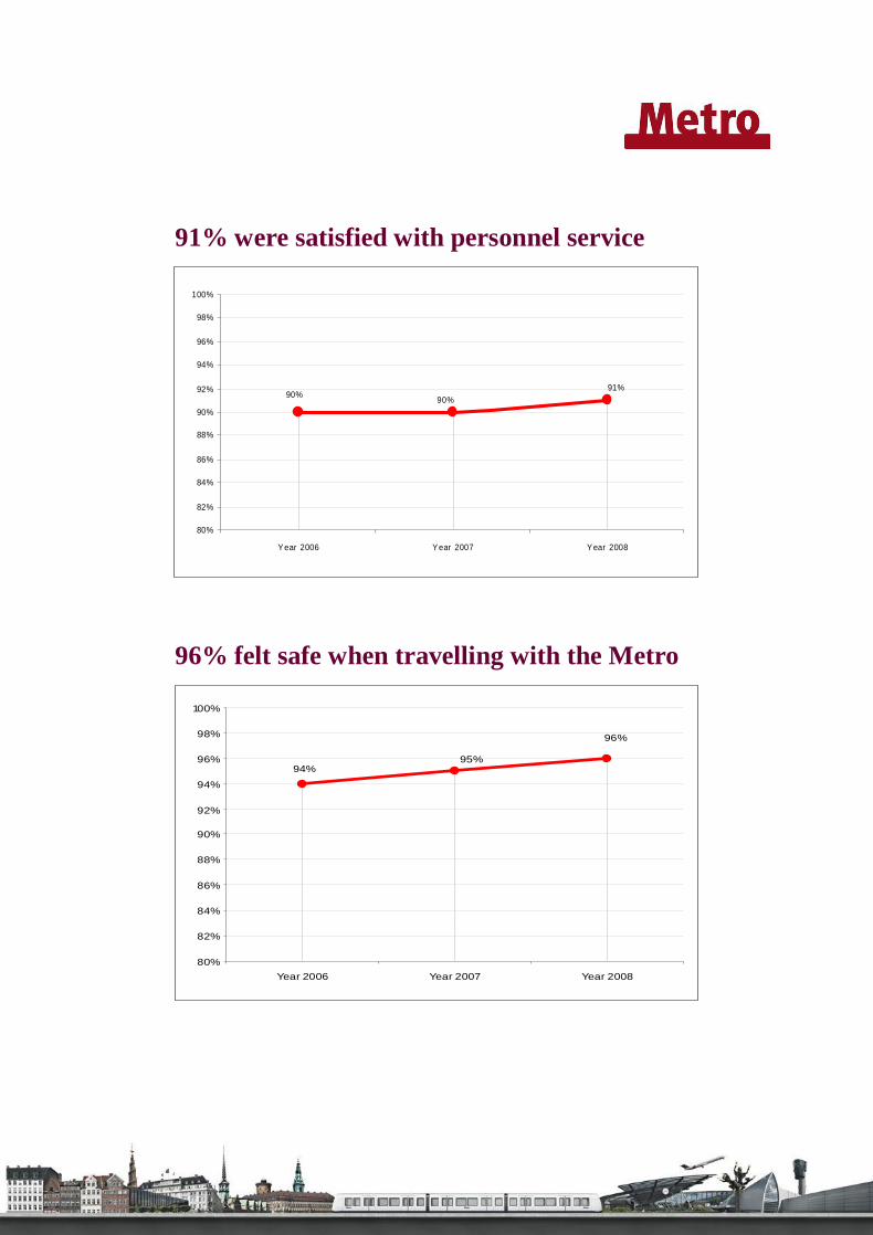
The Copenhagen Metro The Copenhagen Metro first opened in 2002 and now, seven years later, the system is com-pleted: 13.05 miles of high technology transportation connecting vitals parts of Copenhagen and providing faster, safer and more convenient travel choices than ever before. The two lines with 22 stations take the passengers from Copenhagen Airport, across the city centre and in onto the densely populated suburbs, crossing areas of new urban development. Passenger volume In 2008 the Copenhagen Metro had a staggering growth of 17 % in passenger volume, which brought the total passenger number to 46 million, which is a high number compared to the number of inhabitants in greater Copenhagen area, which in 2008 was approximately 1.8 million. Service availability in 2008 New records where set in 2008. Service availability overall for the year was 98.6 %, and in January 2008 a monthly record of 99.4 % was achieved. Number of daily departures is 12,000 with a head way in rush hour of 125 seconds. De-creased headway of 10 seconds in rush hour compared to 2007. Headway outside rush hour is 6 minutes and at night time from Thursday to Saturday head way is 15 minutes. Customer Satisfaction improved in all areas in 2008 Not only did the number of Metro passengers increase a lot in 2008, they were also more satisfied with our service. Last year the overall customer satisfaction rose from 95% (in 2007) to 97%. The service availability record could also be measured in the customer satisfaction, where no less than 95% were satisfied with the time table reliability compared to 90% in 2007. The number of passengers not satisfied with the reliability in 2008 were down to 3%. 91% were pleased with personnel service and 96% felt safe when travelling with the Metro while only 2% answered that they did not feel safe.

97%
95%96%
80%
82%
84%
86%
88%
90%
92%
94%
96%
98%
100%
Year 2006 Year 2007 Year 2008
97% were satisfied with their journey
95%
90%89%
60%
64%
68%
72%
76%
80%
84%
88%
92%
96%
100%
Year 2006 Year 2007 Year 2008
95% were satisfied with timetable reliability
94%
96%
95%
80%
82%
84%
86%
88%
90%
92%
94%
96%
98%
100%
Year 2006 Year 2007 Year 2008
91% were satisfied with personnel service
96% felt safe when travelling with the Metro
91%90%90%
80%
82%
84%
86%
88%
90%
92%
94%
96%
98%
100%
Year 2006 Year 2007 Year 2008

24/7 service introduced in March 2009 Throughout the last six months of 2008 we have tested operations in a 24/7 scenario, and we are now from March 2009 ready to introduce a 24/7 service to our passengers, with a head-way from Sunday night to Thursday night of 20 minutes and a head way from Friday and Saturday night of 15 minutes. This means that all track maintenance activities will be per-formed in a timeframe of 4 hours each night, with the exception that every 8th week night busses will be put in from Sunday night to Thursday night. The Copenhagen Metro will by introducing 24/7 operations be one of the first - if not the only - driverless Metro operating 24/7 within a two track system, which means maintenance activities will be performed in one track, while at the same time service will be carried out on the other track. This has been made possible by implementing independent switch control on the whole system. All alterations have been performed in 2008. Planning all maintenance activities to take place within such a short timeframe during the night has been a huge, chal-lenging effort and demanded/will demand professionalism and skill from maintenance and operational management, technical and control room staff not to mention service personnel. New extension – a circle line The fourth phase of the Metro in Copenhagen – the City Ring - is expected to open in 2018. The route of the City Ring will run underground and consist of 17 stations that cover major parts of the city centre as well as the Østerbro, Nørrebro, and Vesterbro districts and the Mu-nicipality of Frederiksberg currently not covered by S-train or Metro line service. A round trip is expected to take 23 minutes. It is expected that a total of approximately 80 million travelers will use the Metro each year, when the new extension opens. See more about the City Ring on www.intl.m.dk Metro Stations The fundamental philosophy of the design has been to establish effortlessly operating Metro stations that give passengers ideal conditions when accessing from street level to platforms. Since the Metro has a long life expectancy , the design of the Metro is made to blend in with and enhance its urban surroundings – both in the existing city and the new Ørestad. To achieve this delicate balance, the stations – like the other parts of the Metro – are kept in classic, functional Scandinavian design. The implementation of a new system in the middle of a larger city takes a lot of effort. The planning, construction, integration and testing have been strictly and mutually controlled ac-cording to the contract with the Danish authorities. Around 800 contractual milestones and dedicated, international teamwork lead to the Metro opening as planned and made sure that from the very first day it became an integral and much favoured part of Danish public trans-port. Metro Architecture Underground stations are practical, with good access from the street and from other transport

links. Moreover, it has a timeless design that blends in naturally with the street and clearly signals the Metro station. The Metro has 22 stations, 9 of which are tunnel stations. 12 km of the line run on embank-ment or elevated railway while 11 km are underground. Information at stations The Metro landmark is a five meters high Metro pillar. From far away the pillar signals that this is a Metro station. The five meter high pillar’s electronic display shows information about departures. The Metro pillar is designed by Knud Holscher Industriel Design. In the stations’ halls you’ll find general information about the Metro, a map of the route, in-formation about the surrounding part of the city and general public transport. On the plat-forms electronic displays tell when the next Metro is arriving. Elevated railway stations The stations on the elevated railway and embankment are made from glass and steel that seems to rest between the two tracks. This creates an easy, almost floating design. The “lightweight” stations are created in order to avoid that the stations dominate the surround-ing landscape. In contrast to the tunnel stations, there are no platform doors to screen the platform from the tracks. Instead an electronic monitoring system ensures that the train stops immediately if foreign bodies get on to the track. Tunnel Stations From the ground the tunnel stations don’t stand out. Mostly the area around the descent ap-pears as a square in the urban surroundings. On the square you see the pyramid-shaped sky-light inlets and a glas and steel elevator that sticks more than 4 meters out of the ground. Furthermore, there is a staircase and the pillar. Elevators and escalators In the hall there are two escalators going up from and two going down to the platform. In-stead of that escalators the users can use the lift. The lift is made of glass to ensure the com-fort of the passengers. Light at the stations The pyramids are asymmetric with the objectives 3.5 meter x 3.2 meter The height is 2.2 me-ter And through these skylights the daylight shines into the station and down on the platform 18 m underground. The daylight is enhanced by using daylight reflectors , made from pol-ished aluminum panels. At the same time the sunbeams hit acrylic prisms, mounted in the pyramid. Through these prisms the light is decomposed like in a rainbow and the sunbeams are transported down into the station.
Artificial light Light sensors measures the amount of light in the stations and if more light is needed – in overcast weather or at dusk – the reflected sunlight is supplemented by artificial light in or-der to ensure that the light at the stations is always more or less at the same, pleasant vol-ume. The designers of the light Skylights, reflectors and prisms have been designed by architects KHR AS, in cooperation with the Austrian light experts Bart Bach Licht Labor. Smoke-free escape route Due to electrically run spindles the pyramids can be raised 60 cm. This ensures the smoke ventilation needed to guarantee a smoke-free escape in a fire situation. At the same time the mechanism allows for the glass to be cleaned and well maintained. Ventilation Houses The ventilation of the tunnel station is made possible via a 3.7 meter high ventilation houses made from glass and steel. The ventilation buildings are placed on a plinth in light gray gran-ite. Staircase From the street level two stairways made in light gray granite and surrounded by solid glass lead down to the platform. On the inside the stairs are covered with light gray granite on both steps and walls. The handrails are constructed from stainless steel and the light fittings are inlaid in the walls. Some tunnel stations, among them Kongens Nytorv, have a circular staircase. The staircase is made from light gray granite, surrounded by a solid glass shield. Outside the main stair-case is a app.. 1.3 m wide, cast iron ventilation grate. The main staircase is approximately 11 meters in diameter. The inside of the stairs are cover with light gray granite, both on the steps and walls. The handrail is made from stainless steel and light fittings are inlaid in the walls. Bicycle Basement Six stations are equipped with bicycle basements. From the bicycle basement there is access to the station hall and from there escalators lead down to the platform. Glass on the platform On the platform glass walls are screening off the tracks. The doors in the glass wall open si-multaneously with the train doors when a train stops at the platform. The principle is the same as with modern elevators and has a number of security advantages: It ensures that the passengers do not fall or jump unto the tracks Easier, cheaper and better control of ventilation in the stations and the tunnel

Improved indoor climate Increased safety for visually impaired passengers The system The overall principles for the Copenhagen Metro are: light trains (128 feet long) on an inten-sive headway with flexible interior executed with the state of the art design. If you add the very high demands on operation, environmental and safety issues, it becomes evident why Copenhagen has become the centre of international interest, when it comes to Metro sys-tems. The Copenhagen Metro is a driverless system that is operated and maintained around the clock and complies with very high demands on design, safety, service availability, passenger service, and reduced environmental impact. The railway system, including all sub-systems, that has been chosen for the Copenhagen Metro shows a fine balance of two main requirements: 1. It is a technologically advanced and well-integrated system in order to meet the de-
mands of being driverless, safe, future-proof, and operating around the clock. 2. Nevertheless most of the chosen solutions are based on well-known technology and on
experience from all over the world in order to ensure performance stability. Sub-systems: Rolling stock Control and Maintenance Center with service vehicles and equipment Automatic Train Control (ATC) SCADA (Supervision, Control, and Data Acquisition) Radio, Communication, PSIS (Passenger Safety and Information System) Power supply and Traction power Permanent Way Platform Screen Doors Obstacle Detection System In the following pages each sub-system and the process of implementation is briefly de-scribed. For further technical specifications see also the listings on the last pages. Rolling stock. The vehicles for the Copenhagen Metro all consist of 3 carriages with articu-lation assemblies, so the train inside appear as one big open room. The design is stylistically consistent and there is plenty of space for bicycles, wheelchairs, prams etc. Large panoramic windows all the way round ensure a good view for the passengers. Each train is 128 ft long, 8.6 ft wide and made of aluminium. Each train has 4 bogies – of which 3 are with motors. The maximum speed is 50 mph and the average speed including stops at stations is 25 mph. Control and Maintenance Center. The center consists of 11,000 m2 of buildings, which in short includes control room, emergency control room, all facilities for maintaining the trains, automated washing hall, hall for interior cleaning, hall for removal of graffiti, power supply

units and administration. Apart from the buildings there are 5 km of tracks within the prem-ises for parking and shunting trains and an 800 m long permanent test track for testing trains after maintenance and repair. The area is fenced and secured against intrusion for safety rea-sons (live tracks) – and to prevent vandalism. ATC (Automatic Train Control) – the key to automation. The driverless Metro is operated by technical systems, all kept under surveillance by the operators in the control room in the Control and Maintenance Center in Ørestad. The technology ensures that the trains stop at the right place at the stations, open and close the doors, leave the stations, keep the correct speed and keep the secure distance between the trains etc. All this happens by means of sys-tems integrated in the trains, on the tracks, on the stations and in the control room: ATC (Automatic Train Control). ATC consists of 3 systems each having its own purpose: ATP (Automatic Train Protection) ensures that trains on the track keep the correct
distance between themselves at any time and that switches are set correctly. The sys-tem constantly surveys the position and the speed of the train and will automatically intervene, if it becomes necessary to adjust the speed or to stop the train for safety rea-sons.
ATO (Automatic Train Operation) is an autopilot system, which ensures that the trains stop at the right position at the platform, open and close the doors and adjust the speed within the limits imposed by the ATP. An ATO system is, contrary to a train driver, capable of surveying the entire operation and monitoring the status of each ve-hicle.
ATS (Automatic Train Supervision) is the superior traffic and survey system. It con-trols and coordinates all traffic and maintains a schematic review of the entire Metro for the operators in the control room. It controls the arrival and departure of trains from all stations and also includes automatic vehicle dispatching, automatic routing, sched-ule control, and zone speed restriction.
SCADA. (Supervisory Control And Data Acquisition). SCADA is a system that makes it possible from the control room to monitor all equipment on stations, in trains, along the tracks, and in the Control and Maintenance Center itself. By a comprehensive system of sen-sors and devices the Control Room operator can check that the circuit breakers, isolators, escalators, lifts, fire fighting equipment, ventilation, elevators, and every other equipment in the entire Metro are working properly. Furthermore several commands can be executed by the operator to change to status of the above mentioned components: circuit breakers and isolators can remotely be opened and closed, ventilation fans can be switched on, elevators can be stopped and escalators be reversed when required etc. Communication. Outside the stations, on the platforms and inside the trains there is infor-mation for the passengers on screens and signs and via loudspeakers – and the Metro Stew-ards around the system can answer questions at any time. In this way the Metro provides clarity and ease of travelling. Furthermore, passengers can get relevant information about the Metro from the Customer Service Centre as well as following the operation in real-time and browsing all sorts of Metro information on www.m.dk.

In all trains, in every station, and along the line between stations and rescue shafts, call-points have been installed from where the passengers by pressing a button can get in direct contact with a Metro operator in the control room. There is also a button for emergency calls, which always will be given first priority by the system. In short these systems consists of all the connections that it takes to control the rest of the systems, inform the passengers and supervise their safety in stations and in trains. The sys-tem provides:
Radio link - between control room and service personnel - between the passenger vehicles and the control room - between the service vehicles and the control room
Telephones Passenger Information Display (PID) in trains and on platforms Loudspeaker system with both programmed and real-time announcements Call-points with contact to control room from both trains, platforms and line Video survey of trains, stations and the Control and Maintenance Center Recording, both visual and auditory. Over 220 cameras are installed on the 17 sta-
tions and 34 trains. The system can be programmed for the most suitable type of survey for the occasion. For instance, monitors will always automatically show a passenger using one of the call-points, so that the control room operator can immediately get an impression of the situation where the call has been made from. The passengers can hear and read relevant information both inside the train and in the sta-tions. There is automated information about the service – for instance about when the next train will arrive etc. – but also immediate information if any irregularity occurs or other things of interest for the passengers. Power and Traction. Three independent 10.5 kV rings supply the Copenhagen Metro. In total eight different electrical utility feeds are supplying the connected rings. If there is a fail-ure in one point of the ring, the system can be reconfigured to ensure the power supply to the stations of the ring is maintained. Every station is equipped with two redundant 10.5/0.4 kV transformers to provide a power supply to all of the sub-systems installed in the station (e.g. ATC, SCADA, PSIS, Radio, Ventilation, etc.) A sub-set of these sub-systems is fed via an Uninterruptible Power Supply (UPS) system to ensure the availability of the sub-system even when the power supply is completely missing in the 10.5 kV ring. 10 of the 22 stations are also equipped with rectifier transformers and inverter transformers to supply the conductor rail (also called the third rail) at 750V DC and to return the braking power produced by the trains on the line. This third rail system supplies the required power to the passenger vehicle via collector shoes installed on each motorized bogie of the train (six in total, three per side).
Permanent way. The permanent way is made of UIC54 tracks with a standard gauge of 1435 mm On elevated parts of the line and on embankments the tracks are ballasted. In the tunnel a slab tracks with blocks and rubber boots are used. Switches are of the “swing nose” type – also called movable frogs – which are new to Denmark. Platform Screen Doors. All underground stations are equipped with platform screen doors, which completely separate the platforms from the tunnel area. This increases the comfort for passengers in the station, as they are spared the inevitable wind from the tunnel. Furthermore the platform screen doors have the purpose of optimizing safety as they can entirely prevent any access from platforms to the tunnel and subsequently to the track areas. Any unsched-uled opening of the doors will cause the immediate stopping of all trains running in that spe-cific tunnel section. The transparent sliding doors, made of glass, are controlled by the ATC system and open only simultaneously with the doors of the train, when the train stops at the station. Obstacle Detection System. While the platform screen doors provide protection for passen-gers on the underground stations there is another safety system for the above ground stations. At all above ground stations, either a system of closely spaced infra-red rays or a laser beam scanner secures that the system reacts immediately if someone or something falls down on the tracks. If this occurs the approaching train will be stopped before entering the station.

Technical Specifications
Rolling stock Total fleet: 34 vehicles Bidirectional three-bodied Length: 39 m Width: 2.65 m Weight: 52 tons Body: Aluminium Doors: 6 double doors on each side Capacity: 300 persons Maximum speed: 80 km/h Acceleration in operation: 1.3 m/s Braking in operation: 1.3 m/s IGBT converters on vehicles supplied by contact shoes (three on each side of the vehicle) Control and Maintenance Center 118,40 ft² of buildings including: Control room Extra/emergency control room Workshops for:
- Maintenance - Automatic exterior cleaning - Automatic operation for manual interior cleaning - Graffiti removal facility
Administration block Power station
- Rectifier rated power: 1500 kW - Auxiliary power supply (transformer): 16 kVA
Service vehicles - 1 general service locomotive for removal of failed revenue vehicle
- 1 light diesel rail service vehicle for maintenance - 1 heavy diesel rail service vehicle for maintenance - 1 commercial road truck - 1 tunnel washing road/rail machine
3,11 miles of tracks including: 2.624,67 ft of permanent test track mounted with all equipment to be found on
the Metro line tracks for the shunting and storage of trains

Automatic Train Control (ATC) Driverless operation through ATC consisting of:
- Automatic train protection (ATP) - Automatic train operation (ATO) - Automatic train supervision (ATS)
Equipment for line (stations and wayside): - Interlocking Microlok II - Track Microlok II - AF902 track circuit controller - Non vital logic emulater (NVLE) - TWC transmitter receiver - TWC loops - AFOIIC units - Coupling units - Transmitters (Tx) - Receivers (Rx)
Functions for line (stations and wayside), for example: - Train detection - Speed command transmission - Interlocking control - Speed restriction - Berthing - Automatic coupling - Direction control - Train separation - Emergency stop - Train-to-wayside communication - Platform screen door interface
Equipment for vehicles: - Vehicle Microcab II - TWC antennas - Pick-up coils (PUC)
Functions for vehicles, for example: - Speed limit reception/decoding - Speed monitoring - Vehicle overspeed protection - Brake assurance - Propulsion/braking interface - Door control - ATC failover - Automatic coupling - Vehicle direction control - Automatic train operation - Train-to-wayside communication
Equipment for control room:
- Two hot-stand-by system servers - Monitors - Workstations
Functions for control room, for example: - Automatic train supervision - Signalling, route, control and display - Vehicle regulation and schedule management - Status reporting and alarm generation - Vehicle control and monitoring functions - Emergency stop requests
SCADA (Supervisory Control And Data Acquisition) Architecture mainly based on PLC units located in each station and shaft for the control and monitoring of: Power Supply and Traction Power systems (isolators, high voltage circuit breakers, power supply reconfiguration, etc.) Equipment in each station (elevators, escalators, fire fighting tools, drainage pumps,
etc.) Equipment in vehicles (doors, fire/smoke sensors, etc.) Tunnel emergency ventilation system
Each PLC is monitored through the communication network by two hot-stand-by servers placed in the Control and Maintenance Center
Communication Closed circuit TV surveillance of stations and trains Tetra radio communication between the control room, vehicle, station and line. Public address system in stations and trains Information displays in stations and trains Call point with direct control room contact in stations, wayside and trains Power supply and Traction power External sources: 10 kV, 50 Hz High voltage circuit breakers Two transformers – one for redundancy UPS 380 V, 50 Hz No. of substations: 10 mainline plus depot consisting of mono group with recti-
fiers (750 V DC) and mono group inverters for regenerative braking and power reversal to 10 kV line
Third rail isolators Insulation covered bottom contact third rail system formed from an aluminium
conductor with a stainless steel contact surface
Permanent way UIC54 profile running rail Gauge 1435 mm Ballasted track on above ground sections Concrete slab with blocks in rubber boots in tunnel sections Movable frogs of the swing nose type
Platform screen doors Installed in each of the nine underground stations Six sliding doors and additional twelve hinged emergency doors on each side
of the platforms. The system is operated under the control of the ATC system
Obstacle detection system The system is based on two different technologies. Both are operated under the con-trol of the ATC system.
Infrared beam array equipment (installed in phase 1): Installed in the five stations of the above ground section There are approx. 48 bars installed in each station depending on the exact
length of the platform Each bar contains 8 transmitter/ receiver pairs giving a total of 16 beams. Laser beam scanner (installed in phase 2B and phase 3 stations: Installed in the three stations of the above ground section (phase 2B) and four
stations (phase 3) Each platform has multiple sensor heads continuously scanning the track area. Objects are detected by the laser beam striking an obstacle within the moni -
tored field.