the cracking, deflection and collapse behaviour df a ... · the cracking, deflection and collapse...
TRANSCRIPT
The Cracking, Deflection and Collapse Behaviour Df a Series Df Reinforced Brickwork Beams
T.G. Garwood, M.A., Ph.D., C.Eng., M.I.C.E., Senior Lecturer
A. Tomlinson, B.Sc.(Hons)., Research Assistant
Department cf Civil Engineering, Eolton Institute of Technology, Eolton, England.
sm!MARY
This papar describes the construction and testing cf a series of eight reinforced brickwork beams in which the quantities cf tension and shear reinforcement were varied. The test- performance of the beams i5 examined from the points of view of safety and serviceability, and the current design recommendations are assessed . An empírical- load-deflection relationship for, reinforced brickwork beams i5 proposed.
1. INTRODUCTION
During the past fifty years, the general behaviour of reinforced brickwofk beams hjS been investigated . in several research projects ',2,3,4,5. However, relatively little has been published with regard -to deflection and cracking. If reinforced brickwork beams are to be used more widely as structural flexure members, then it would be desirable to be able to predict the extent of deformation and local damage that is likely to occur undar service conditi·ons. Therefore, a series of beam tests was planned in which particular attantion would be paid to these serviceability limit states.
When designing the beams, ce rtain factors were taken into account. Firstly, the construction of the beams had to Q~ reasonably simple and practicable; secondly, the a rra ngemJnt of brickwork had to be such that both tension and shear reinforcement could be accommodated in a straightforward manner j and, thirdly the number af test variables was to be kept to a minimum. With these considerations in mind, a suitable design was evolved. An important feature af the design was that the tensian and shear reinforcement could be varied without having to alter the brickwork details.
481
2. CONSTRUCTION OF THE BEAMS
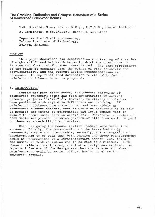
The beams were 3905 mm long, 328 mm wide and 290 mm, ar faur courses, in depth. The first twa courses were laid in stretching bond and the top tWQ course s in Quetta bonde The details af a typical beam are shown in F i g. 1.
Ál 8"9
I :: : I I I
I : I I: 11:
I I I
I I : I:
I I
11: : I I : I : I I: : I I I I I I
II I II I I
Elevalian A..d B..d
328 mm
290mm f~~~~:J~~~ ____ --IGroUled _______ -f~~~; ca vily
A- A B-B
Fig 1
The beams were built on a s teel channel supported centrally _and at the ends. After applying a coat cf mould oi1 to the channel, the two caurses i n st r e t ching bond were laid. By. omi~ting the central lin e of bri cks in the second c aurse, a longitudinal cavity, 130 mm wide and 75 mm deep was created; the reinforcement cage was then p l ac ed in t his c avity. The upper twa courses were then laid in Quetta b ond, leaving the shear reinforcement in a series of pockets 1)0 mm wide a nd 67.5 mm long at 167.5 mm intervals . Becau se t wo t ypes of bonding were used, care had to be taken wh en setting ou t t he bri ckwork to avoid co- incident vert ical joints i n the se cond a nd third courses of the be·am~ After completion of t he brickwork, the void surroWlding the main reinforcement and the pocke ts enc losing the shear reinforcement we re grouted.
There are several point s a bout this beam design which are worth noting. Fi rstly, by laying t he t wo l ower courses in stretching bond, the line of the ten s i o n r e inforcement is unobstructed by h e aders. Secondly, by using Quetta bond for the upper two courses there is adequ at e cerami c interlock in the beam and wire ties are n ot necessary . Thirdly, with this arrangement of brickwork, the volume of g r out is minimise d and thus the effects of grout shrinkage are reduced. Finally, it should be pointed out that, because of t he heade r s in the top course, t h e re were no longi"tudinal top bars t o ancho r the s tirrups as in a conventional reinforced conc rete beam.
Wi th ane bricklayer and one l a b oure r, a beam could be buil t in one and a half days.
482
3. MATERIALS
3.1 Bricks
These w'l6j BS 3921: 1974\ The bricks were perforated with
Class B engineering bricks , complying with and manufactured by George Armitage and Sons nominally 215 mm X 65 mm X 102 mm and were three 30 mm diameter holes.
Ltd.
in on
The average compressive strengths 02 the bric~s, determined2 accordance with BS 3921,were 11 8 N/mm , 52 N/mm and 45 N/mm the bed, stretcher and header faces re spectively.
3.2 Mortar
The mortar used for the beams was a 1 :t:J cement f " hydra ted lime and sand mix by v~lume. cube strength of the mortar was 21 N/mm .
3.3 Grout
ordinary Portland The average 28 day
After several trial mixes, the grout s el ected for the beams was a 1 :2.5 cement:sand mix by volume, wi t h a water cement ratio of 0.8'2 The average 28 day cube strength of this grout was 26 N/mm •
3.4 Reinforcing Steel
The tension reinforcement consisted of 12 mm, 16 mm and 19 mm (~ in. Imperial size) Helibond deformed cold worked bars; the shear reinforcement wa s bent írom 8 mm plain mi ld steel bars. The properties of t he reinforcement are given in Table 1 below.
Diameter Modulus of Yield Ultimate & E7asr;liC~ ;y ní:!2) Tensi~( I/I 2 \ 1'vne kN mm Stress N mm
Y12 205.8 0;12.2 6 16.6
Y16 194. 5 453.5 '572 . 9
Y19 196. 8 470; . 4 o;qq . 6
R8 205.2 435.6 520.0
Table Propertie s of the reinforcement .
4. THE BEAM SERIES
The details of the reinforcernent in the beams are given in Table 2. The qu ant ity of main tension steel expressed as a percentage of the breadth times the effe ctive depth (100 AS/bd) varied from 0.34 to 1.33.
Also shown in Table 2 are the design moments of resistance of eac~ Qeam as calculated using the formul ae in the Design Guide t7) with the appropriate characteristic strengths and partial safety factors ()(m values) being u sed. In Table 2, Mb refers to the moment of resistance based on the flexural compressive strength of the brickwork and Ms i s the moment based on the tensile strength of the steel. In these calculations t
the characteristic compressive strength of the bri ckwork was taken as 0.4 X 24 = 9.6 N/mm2 , the factor 0 . 4 being u sed because the direction of the compressive stress was not perpendicular to the bed joints.
483
Beam Main 100 ~ Shear links Design momeltts t)f' Steel bd resistal1ce kNm
Mb Ms
1 2 Y12 0 . 34 R8 at 167 mm 20.24 1'5.51 _
2 2 ' Y12 0 . 34 None 20.24 15.5 I
1 2 Y12 0 . 14 None 20.24 15.51
4 2 Y16 0 . 62 None 19.64 2'1.')'5
'5 2 ' Y16 0 .6 2 R8 at 167 mm 19.64 21. '5 'i
6 2 . Y19 0.89 None 19.24 27.06
7 2 Y19 0.89 R8 at 16~ mm 19.24 27. 06
8 3 Y19 1 .33 (8 at 167)mm 19.24 30.20 1n pa1rs
Table 2 Details of Test Beams.
In the usual limit state design process the smaller design moment of' resistance would be slightly greater than, or equal to, t he moment produced by the design ul timate load. Wi th Yf: factors of 1.4 and 1.6 f'or the dead and imposed loads respectively, the design ultimate load would be approximately one and a half times the service (working) load. In other words, the service moment would be about two thirds of the design moment of resistance. Using this approach, nominal working loads were calculated for the test beamSa For the loading arrangement used, the nominal working load was taken as the value which,together with the seli' weight, produced a mid-span bending moment equal to two thirds of' the moment of resistance. For each beam, two nominal working loads were obtained: one corresponding to · the flexural compressive strength of the brickwork and the other corresponding to the steel strengtha The larger of' these values i5 ref'erred to as the higher working load (H. W.L.) and the lower value is referred to as the lower working load (L.W.L.).
According to the Design Guide, of' the eight beams in the series, beams 4 and 5 would be the closest to a balanced sectionj beams 1, 2 and J would be considered under-reinforced and beams 6, 7 and 8 over-reinf'orced.
In beams 1, 5 and 7 the shear reinf'orcement consisted of' 8 mm links at 167.·5mm centres, this quantity providing an ASv/sv value* slightly 1ess than the minimum nominal amount suggested . in . the Design Guide. In beam 8, the shear reinforcement was twice that in beam 7.
When the first two beams had been completed,another bricklayer was employed to build the remainder of the series. Thus, in order to assess the effects of possible differences in workmanship, the quantity of reinforcement in beams 2 and J was kept the sarne.
484
* Asv sv
= =
cross -sectional area of legs of a link spacing of links

5. TESTING OF THE BEÀ~S
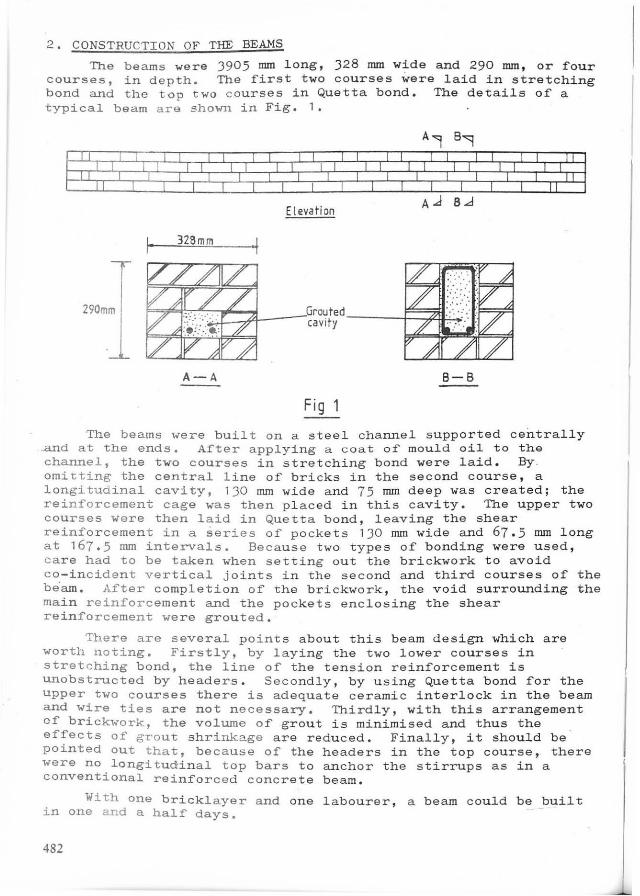
The first seven beams of the series were tested in a 500 kN capacity "self-straining" test frame. The load was applied by a hydraulic jack, via a proving ring and spreader beam, at two points on the beam; the loading configuration is shown in Fig. 2. The eighth beam was tested in a 2500 kN capacity Avery Denison universal machine, the sarne faur point loading being applied.
1173mm 600mm 600mm 1173 mm
Load
11 11
.l'i h
Beam bed
Fig 2 Loading arrangement
AlI beams were subjected to an initial loading cYGle in which the load was increased from zero to the higher working load and then ret~rned to zero. The load was applied in suitable increments at each of which the central deflection, steel and brickwork
· strains and crack widths were measured. The sarne procedure was used in the second loading when the beams were tested to destruction.
The central deflection at each side of the beam was measured with adiaI gauge. The brickwork strains at mid-span were me~sured with a 900 mm Demec gauge t there being seven gauge lengths on each side of the beam. The strains in the tension steel were obtained from electrical resistance gauges. Crack widths were measured with a microscope having a magnification of 40; in some cases the crack width could be calculated indirectly from the Demec readings.
6. DISCUSSION OF TEST RESULTS
6.1 Deflection
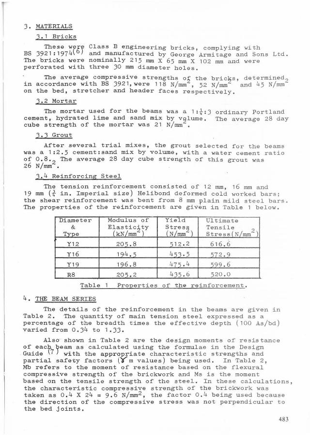
The experimental load-deflection curves for the eight beams are shown by the unbroken lines in Fig. J. These curves refer to the initial loading from zero to the higher working load; above this t the curves refer to the second loading.
485

... &01 60 601 60 00 / a-
50 50 /, 50 / 50 ' /' /
" ~/'~O /' / ~O BfAM 1 / ~O BEAM 2 BEAM 3 ,/ ~O BEAM ~
= ,/ /' / /. -'" /'
30 ,/ /' 30 ~ 30 /' /' 30 /' ~ ,//' ,/ /'
,/ /' _. __ .-.-~ 20 ,/
_ ._fj.\Ü . 20 /' 20 /' 20 ~ . __ .-L. '-'-7: --'- '- ' - ' - ._ ._ ._.-
._ ._ ._ ._ .Lw'L. /. '-' - '--10 10 10 10
I
O 5 10 15 20 25 O 5 10 15 20 25 O 5 10 15 20 25 30 O 5 10 15 20 OEfLECTION mm
70 70 70 70
60 /
60 60 &0
50 BEAM 5 / 50 BEAM 6 50 BEAM 7 50 BEAM S / I
/ / ~O / W ~O / ~O = / "'" /-
/ = lJ 30 30 /, 30 4 = ,z_.H.W.L. '-'-'--' 20 20 20 20 '/ ._L!fIl.. ._._.- ._ . -
10 10 10 10
O 5 10 15 20 25 O 5 10 15 20 25 O 5 10 15 20 25 30 O 5 10 15 20
Fig,3 LOAO-OEFLEC1IOK CURVES I Ex2erimental Pro ~OSf d pm~irical
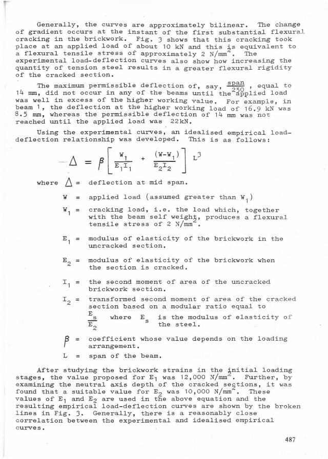
Generally, the curves are approximately bilinear. The change of gradient occurs at the instant of the first substantial flexural c racking in the brickwork. Fig. J shows that this c racking took p lace at an applied load of about 10 kN and this ~s equivalent to a flexural tensile stress of approximately 2 N/mm . The experimental load-deflection curves also show how increasing the quantity of tension steel results in a greater flexural rigidity o f the cracked section.
. The maximum permissible deflection of, say, span , equal to 14 mm, did not occur in any of the beams unt il the2~Bplied load was well in excess of the higher working value. For ~xample, in beam 1, the deflection at the higher working load of 16.9 kN was 8. 5 rnrn, whereas the permissible deflection of 14 mm was not reached until the applied load was 22kN.
Using the experimental curves, an idealised empírical loaddeflection relationship was developed. This is as follows:
where 8. =
10' =
10', =
E, =
f =
+
deflection at mid span.
applied load (assumed greater than 10',)
cracking load, i.e. the load which, together with the beam self weigh~, produces a flexural tensile stress of 2 N/mm •
modulus of elasticity of the brickwork in the uncracked section.
modulus of elasticity of the brickwork when the section is cracked.
the second moment of area of the uncracked brickwork section.
transformed second moment of area of the c r a cked section based on a modular ratio equal to E 2. E
2
where E s
is the modulus of elasticity of the steel.
coefficient whose value depends on the loading arrangement.
L = span of the beam.
After studying the brickwork strains in the ~nitial loading stages, the value proposed for E, was '2,000 N/mm. Further, by examining the neutral axis depth of the cracked se2tions, it was f ound that a suitable value for E2 was '0, 000 N/mm. These values of E 1 and E2 are used in the above equation and the resulting empirical load-deflection curves are shown by the broken l ines in Fig. J. Generally, there is a reasonably close correlation between the experimental and idealised empirical curves.
487
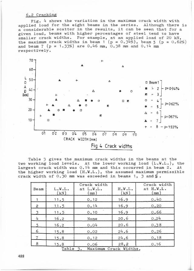
6.2 Cracking
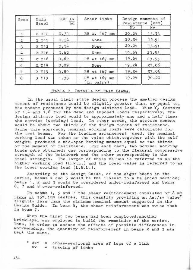
Fig. 4 shows the variation in the maximum crack width with applied load for the eight beams in the series. Although there is a considerable scatter in the results, it can be seen that for a given load, beams with higher percentages of steel tend to have smaller crack widths. For example, at an applied load of 20 kN, the maximum crack widths in beam 1 (p = 0.J4~), beam 5 (p = 0.62~ ) and beam 7 (p = 1 .33~) are 0.46 mm, 0.38 mm and 0.14 mm respectively.
70
60
L 50 O A O 40
(kN]
30
ZO
10 ;.
0-1
.. ;. ..
;. .. Á o
• o
O-Z
+ .. ó. • o
o Seam1} • \, Z p: 0'34%
OI " 3
A • • o o " ó. • o "
o 45
}P"0'6Z% . " • • o
A " "
j- 8 - p: 1-33%
03 O-I. 0-5 0-6 0-7 0-8 0-9 1·0 CRACK WWTH (mm]
Fi 9 4 Crack IV idftls
Table 3 gives the maximum crack widths in the beams at the two working load leveIs. At the lower working load (L.W.L.), the largest crack width was 0.14 mm and this occurred ~n beam 2. At the higher working load (H.W.L.), the assumed maximum permissible crack width of 0.30 mm was exceeded in bearns 1, 3 and 5 .
Crack width Crack width Beam LL~NÍ" at (~iL. H1~~· at H.W.L.
(mm)
1 11.5 0.12 16.9 0.40
2 11 .5 0.14 16.9 0.20
3 11.5 0.10 16.9 0.66
4 16.2 None 20.6 0.24
í 16.2 0.04 20.6 0.18
6 15.8 0.02 24.6 0.26
7 15.8 0.12 24.6 0.18
8 15.8 0.06 28,2 0.16 Table 3. Maxlmum Crack Wldths.
488

6.3 Collapse
The values of the maxirnum loads carried by the beams and the corresponding modes cf failure are given in Table 4 below.
Beam Main Shear Lin.k.s Max.Load Mode of Failure Steel (kN)
1 2 Y12 R8 at 167mm 38.6 Yield of steel, very little cracking outside c.m. zone*
2 2 Y12 None 41.9 " _3 2 Y12 None 41.6 " 4 2 Y16 None 78.0 Yield of steel
5 2 Y16 R8 at 167mm 76.8 Yield of steel, plus some sien of brickwork crushine:
6 2 Y19 None 85.8 Yield of steel plus sudden shear failure
7 2 Y19 R8 at 167mm 101. 8 Yield of steel followed by sudden shear failure
8 3 Y19 R8 in pairs 93.6 Sudden shear failure at 167mm at one end
Table 4. Collapse Ioads and modes of failur~.
The first three beams failed by yielding of the tansion steel, there being very little difference in the maximum Ioads. By comparing beams 1 and 2, it is evident that the shear reinforcement in beam 1 had little, ir any, effect on its performance; when comparing beams 2 and ), which were built by different bricklayers, it appears that the ultimate behaviour was not affec~ed by any differences in workmanship.
In beams 4 and 5, yielding of the steel was again the primary cause of failure. In beam 5 there was also some slight crushing of· the brickwork befora the maximum load was reached. The maximum loads carried by beams 4 and 5 were practically identicalj this suggests that the shear reinforcement in beam 5, as in beam 1, was not brought into action.
Beam 6, which contained no shear reinforcement but a greater area of main steel, failed suddenly in diagonal tension at a load corresponding to a shear stress of 0.74 N/mm2 . In beam 7. which contained the same ma in steel as beam 6, the apparent effect of the shear reinforcement was to increase the load capacity by nearly 19 per cent.
The final beam in the series, beam 8, contained fifty percent more tension steel and twice as much shear steel as beam 7. It was therefore surprising when this beam failed suddenly in shear at a load of 93.6 kN. The apparent cause of this unexpected failure was poor adhesion between the mortar and the bricks.
The overall factor of safety against collapse could be defined as: Collapse moment divided by working load moment. Two values for this factor. using the lower (L.W.L.) and higher (H.W.L.) working load respectively, were calculated for each beam; these values are given in Table 5 over!eaf.
* c.m.: constant moment 489
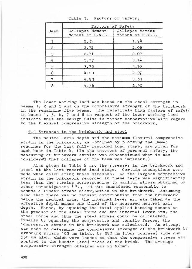
Table 5. Factors of Safety.
Factors of Safety Bearn Collapse Moment Collapse Moment
Moment at L.W.L. Moment at H.W.L.
1 2.53 1 .94
2 2.72 2.08
'l 2.71 2.07
4 3.77 3.14
') 3.72 3.10
6 4.20 2.97
l 4.93 3. 51
8 4.')6 2.90
The lower working load was based on the steel strength in beams 1, 2 and 3 and on the compressive strength cf the brickwork in the remaining .five beams. The relatively high factors of safe ty in beams 4, 5, 6, 7 and 8 in respect of the lower working load indicate that the Design Guide is rather conserva tive with regard to the flexural compressive strength of the brickwork.
6.4 Stresses in the brickwork and steel
The neutral axis depth and the maximum flexural compressive strain in the brickwork, as obtained by plotting the Demec readings for the last fUlly recorded load stage, are given for each beam in Table 6. (In the interest of personal safety, -the measuring of brickwork strains was discontinued when it was consider~d that collapse of the beam was imminent.)
Als"o given in Table 6 are the stresses in the brickwork and steel at the last recorded load stage. Certain assumptions were made when calculating these stresses. As the "largest compressive strain in the brickwork recorded in these tests was significantly less than the strain~ ~orre?ponding to maximurn stress obtained b y other investigators ~ 8), it w'as consider.ed reasonable to assume a linear stress distribution in the brickwork. Assuming also that there was no tensi0n contribution from the brickwork below the neutral axis, the internaI lever arm was taken as the effective depth minus one third of the measured neutral axis depth. Hence, by equating the total applied bending moment to the product of the steel force and the internaI lever arm, the steel force and thus the steel stress could be calculated. Finally by equating the compressive and tensile forces, the compressive stress in the brickwork was calculated. An attempt was made to determine the compressive strength of the brickwork by crushing prisms 102 mm thick, by 290 mm (four courses) wide and 552 mm high, which were loaded 50 that the compressive stress wa s applied to the header (end) faces of the brick. The average compressive strength obtained was 25 N/mm2 .
490
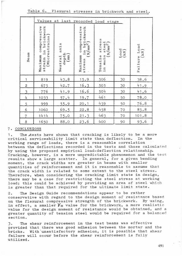
Table 6 . Flexural stresses in br' k lC wor k an d t 1 5 ee . Values at last recorded load sta~e
~"" ~". :> H :> H 'M o 'M o ~ ~~ ~ ~
~ "" ~ ~"" ~ 0 ~ ~ 0 ~ í-o ''''; . ..-1 í-o.r-I- ~..;~
o.H'" ~ o. HN ~ ~N 'O 5 .c M 'M 5 .c 5 H ~ 5
'" o +' ~ o 5 +'+'5 'O~ O~ o ~ ~ '" o ~ ........ ~~ ........ "'z -'1Z 5 'M o .o:~ 'M Z Z O""
"" '" 5 H ";+'ê 5 ~ ~ ~~ -'1~ ~~ ~ ~ ~ 0 '" o. ~ ~ ..; .... H ~ S 'ri '.-I H ~~ 5 ~ .... '" ~
'r-I ro X +''0 .... ~ ~ 5 ..; ~H~ ~ ~ H ~ .... "'+' " "'+' ~ = '" ;:;: ~ Z ;:;: ~ E-< 'M ç..
1 819 4'1.8 1,.9 ,06 30 38.6
2 675 42.7 16.'1 505 30 41.9
3 776 41.9 16.6 504 30 41.6
4 1013 57.4 19.7 461 50 78.0
5 999 55.9 20.1 459 50 76.8
6 1060 69.5 22.8 458 70 85.8
7 1414 75.0 21 .3 463 70 101 .8
8 1650 88.0 23.6 400 90 93.6
7. CONCLUSIONS
1. The ~ests have shown that cracking is likely to be a more criticaI serviceability limit state than deflection. In the working range of loads, there is a reasonable correlation between the deflections recorded in the tests and those c alculated by using the proposed empirical load-deflection relationship. Cracking, however, is a more unpredictable phenomenon and the te st results show a large scatter. In general, for a given bending moment, the crack widths are greater in beams with smaller quantities of reinforcement and it is reasonable to assume that the crack width is reIated to some extent to the steel stress. Therefore, when considering the cracking Iimit state in design , there may be a case for restricting the steel stress at working load; this could be ac~ieved by providing an are a of steel which is greater than that required for the ultimate Iimit s tate.
2. The Design Guide recommendations appear to be rather conserva tive with regard to the design moment of resist a nce based on the fIexural compressive strength of the bri c kwork . By us i ng , in effect, a smaIler Im value for the brickwork, a more reaIisti.c value for the design moment of resistance would be obtai ned, and a greater quantity of tension steel would be required for a bal an c e d section.
3. The shear reinforcement in the test beams was effective provided that there was good adhesion between the mortar and the bricks. With'unsatisfact~ry adhesion, it is possible that she a r failure will occur before the shear reinforcement is fuI ly utilized.
491

ACKNOWLEDGEMENTS The Authors would like to thank George Armitage and Sons
Limited for providing the bricks for the project. The work was carried out in the Civil Engineering Department of Boltao Institute of Technology and the assistance given by the, Technical Staf'f is gratefully acknow!edged. The Authors would a150 like to thank Dr. J. Morton of the Brick Development Associatioo t
D. Foster of Structural Clay Product s Limited and S. Bel1 of George Armitage and Sons Limited for their help and encouragement .
REFERENCES
1. WITHEY, M.O. "Tests of Brick Masonry Beams."ASTM Proceedings 33, Part II, 1933.
2. THOMAS, F.G. and SIMMS, L.G. "The Strength of Some Reinforced Bri ck Masonry Beams in Bending and Shear." Structural Engineer 17, July, 1939.
3. JOHNSON, F.B. and THOMPSON, J.N. "Correlation of Tests of Masonry Assemblages with Strength Characteristics of Reinforced Masonry Beams." Designing, Engineering and Constructing with Masonry Products. Gulf Publishing, Houston, Texas, 1969.
4. SUTER, G.T. and HENDRY, A.W. "Shear Strength of Reinforced Brickwork Beams." Structural Engineer, 53, (6), June, 1975.
5. GARWOOD, T.G. and TOMLINSON, A. "The Design, Construction and Test Performance of Reinforced Brickwork Beams Containing Tension and Shear Reinforcement." Paper presented to the Seventh International Symposium on Load-bearing Brickwork. Briitish Ceramic Society, London, November, 1980.
6. BRITISH STANDARDS INSTITUTION BS 3921 1974. Clay Bricks and Blocks.
7. BRITISH CERAMIC RESEARCH ASSOCIATION. Design Guide for Reinforced and Prestressed Clay Brickwork. Special Publication No. 91, 1977.
8. POWELL, B. and HODGKINSON, H.R. "Determination of Stress Strain Relationship of Brickwork." British Ceramic Research Association Technical Note No. 249, January, 1976.
492