the design and application of a simplified guaranteed service
TRANSCRIPT

THE DESIGN AND APPLICATION OF A SIMPLIFIED GUARANTEED SERVICE FOR
THE INTERNET
Evgueni Ossipov
A thesis submitted to KTH, the Royal Institute of Technology
in partial fulfillment of the requirements for the Licentiate of Technology degree
May 2003
TRITA-IMIT-LCN AVH 03:03 ISSN 1651-4106
ISRN KTH/IMIT/LCN/AVH-03/03--SE
Laboratory for Communication Networks Department of Microelectronics and Information Technology
KTH, Royal Institute of Technology Stockholm, Sweden


i
ABSTRACT
Much effort today in the Internet research community is aimed at providing network services for applications that were not under consideration when the Internet was originally designed. Nowadays the network has to support real-time communication services that allow clients to transport information with expectations on network performance in terms of loss rate, maximum end-to-end delay, and maximum delay jitter. Today there exist two quality of service (QoS) architecture for the Internet: The integrated services, which is usually referred to as intserv, and the differentiated services referred to as diffserv. Although the intserv clearly defines the quality levels for each of its three service classes, the limited scalability of this QoS architecture is a continuous topic for discussion among the researchers. The analysis of the tradeoffs of the two QoS architectures motivated us to design a new QoS architecture which will take the strength of the existing approaches and will combine them in a simpler, efficient and more scalable manner. In this Licentiate Thesis we introduce a guaranteed service for the Internet, which definition is similar to the one in intserv: The guaranteed service (GS) is a network service recommended for applications with firm requirements on quality of end-to-end communication. The service should provide zero packet loss in routers and tightly bound the end-to-end delay. The capacity for a GS connection should be explicitly reserved in every router along a path of a connection. However, in contrary to intserv the necessary quality level will be provided without per-flow scheduling in the core routers, which is the major drawback of the intserv architecture. We use the diffserv principle of dealing with aggregates in the core network since this approach is proven to be scalable and efficient. The thesis considers two major building blocks of the new architecture: The packet scheduling and the signaling protocol. We have developed a special scheduling algorithm. Our formal and experimental analysis of its delay properties shows that the maximum end-to-end delay is acceptable for real-time communication. Moreover, our scheme provides a fair service to the traffic of other service classes. In order to achieve the desired QoS level, a sufficient amount of capacity should be reserved for the GS connections in all intermediate routers end-to-end. We have developed a both simple and robust signaling protocol. The realization of our protocol shows that routers are able to process up to 700,000 signaling messages per second without overloading the processor.


iii
ACKNOWLEDGMENTS
I would like to thank in the first place my scientific advisor professor Gunnar Karlsson for his valuable comments on my work and great ideas that he shared with me in all parts of the topic. I thank him also for patiently guiding me through the obstacles of the research. I would like to thank my colleagues and friends Henrik Lundqvist, Ignacio (Nacho) Más Ivars, Ian Marsh and Héctor Velayos (pure alphabetical order), whose support and attitude continuously motivate me to do a better job. Special thanks (‘big spasibo’) I would like to express to Sir Ian Marsh for his enormous tolerance to my English skills (If you are reading this text now, hope you don’t correct the articles and other stuff on fly – it’s already published, dude!). Apparently this thesis became a very important step in my academic life. Many different and exciting events happened during the work on this document, but none of them would be possible without a constant support from my dear parents and sister. I thank them for their understanding of the importance for me to study and work so far away from my home city. Some time in the middle of the work on the Licentiate I met a person who recently became a very important source of support, love and eternal balance in my soul. I would like to thank you, my lovely wife Katia, just for the reason that you exist in my life.

v
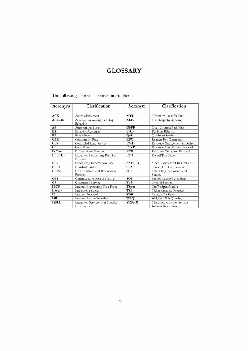
GLOSSARY
The following acronyms are used in this thesis: Acronym
Clarification Acronym Clarification
ACK Acknowledgement MTU Maximum Transfer Unit AF PHB Assured Forwarding Per-Hop
Behavior NSIS Next Steps In Signaling
AS Autonomous System OSPF Open Shortest Path First BA Behavior Aggregate PHB Per Hop Behavior BE Best Effort QoS Quality of Service CBR Constant Bit Rate RFC Request For Comments CLS Controlled Load Service RMD Resource Management in Diffserv CP Code Point RSVP Resource ReserVation Protocol Diffserv Differentiated Services RTP Real-time Transport Protocol EF PHB Expedited Forwarding Per-Hop
Behavior RTT Round Trip Time
FIB Forwarding Information Base SP FIFO Strict Priority First-In-First-Out FIFO First-In-First-Out SLA Service Level Agreement FIRST Flow Initiation and Reservation
Protocol SGS Scheduling for Guaranteed
Service GPS Generalized Processor Sharing SOS Sender Oriented Signaling GS Guaranteed Service ToS Type of Service IETF Internet Engineering Task Force TSpec Traffic Specification Intserv Integrated services TSP Ticket Signaling Protocol IP Internet Protocol VBR Variable Bit Rate ISP Internet Service Provider WFQ Weighted Fair Queuing ISSLL Integrated Services over Specific
Link Layers YESSIR YEt another Sender Session
Internet Reservations


vii
TABLE OF CONTENTS
Abstract...................................................................................................................................... i Acknowledgments ................................................................................................................. iii Glossary .................................................................................................................................... v Table of contents ..................................................................................................................vii Chapter 1. Introduction .......................................................................................................1
1.1 The Internet and quality of service........................................................................ 2 1.2 Service differentiation in the Internet ................................................................... 3 1.3 Network mechanisms for QoS support ............................................................... 4 1.4 A brief history of IP QoS: 1981 - 2003................................................................. 9 1.5 Motivation for the development of a new architecture...................................11 1.6 The framework of a new service architecture ...................................................12 1.7 My contribution.......................................................................................................16 1.8 The structure of this thesis ....................................................................................17
Chapter 2. Scheduling for a simplified guaranteed service .........................................19 2.1 Related work.............................................................................................................20 2.2 SGS: A packet scheduling algorithm for guaranteed service flows...............23 2.3 Modification to the structure of output ports in routers ................................28 2.4 Calculus of the delay bound for SGS scheduling .............................................30 2.5 Experimental study .................................................................................................37 2.6 Summary of our scheduling architecture............................................................47
Chapter 3. Sender oriented signaling for a simplified guaranteed service ..............49 3.1 Signaling protocols in brief....................................................................................49 3.2 Related work.............................................................................................................51 3.3 Basic operations of our signaling protocol.........................................................54 3.4 The message encoding scheme.............................................................................58 3.5 Fault handling in routers........................................................................................60 3.6 Performance evaluation .........................................................................................68 3.7 Summary of the signaling protocol......................................................................74
Chapter 4. The application of a simplified guaranteed service in the Internet .......77 4.1 A circuit-switched Internet....................................................................................78
Chapter 5. Conclusions ......................................................................................................81 5.1 Future work ..............................................................................................................82
Bibliography...........................................................................................................................83 Appendices.............................................................................................................................87
Appendix 1. SGS scheduling. ......................................................................................87 Appendix 2. Processing signaling messages in routers...........................................88 Appendix 3. Classification and processing of GS packets in core routers.........89


1
CHAPTER 1. INTRODUCTION
The progress of network technology which we have witnessed in the last years has made the Internet an essential part of everyday life. The Internet of the 21st century should provide a transport not only for data communications, but also for voice and multimedia. However, the success of the Internet protocol has also led to two major problems facing the Internet today: The lack of sufficiently fast switching equipment and support for real time services. The first problem comes from an increasing demand on communication capacity. The second problem comes from the fact that the Internet was not designed to transmit real-time data. Our research concerns the architectural design for quality of service (QoS) provisioning, and the development of fast routers that are able to handle the increasing traffic volume on the Internet. Specifically this thesis considers the design of a network service, intended for applications with strict requirements on the end-to-end delay and no tolerance to packet loss. The two major components which allow the delivery of such a service to the applications are a special treatment of users data in the network and explicit reservation of the capacity on all links from a source to a destination. In technical terms, the special treatment of users data is done by scheduling, and the reservation of the link’s bandwidth is achieved using a signaling protocol. Our focus is the formal and experimental evaluation of the delay properties of the scheduling algorithm which was proposed for this type of service and the design and experimental evaluation of a new signaling protocol. The purpose of this introductory text is to give some background information on the major areas of the research presented in this thesis. We begin with a general description of the Internet architecture and proceed with definitions of the terms used in this thesis: Quality of service, QoS signaling, and scheduling. We give an introduction to network calculus which we will use to analyse the properties of our QoS architecture. We will then guide the reader through the history of the development of QoS architectures. After highlighting the drawbacks of the existing approaches, we will give our motivation for the development of a new QoS architecture. Finally we will describe the framework of our research and state
2
our contribution in each area. The structure of the thesis is presented at the end of this chapter.
1.1 The Internet and quality of service
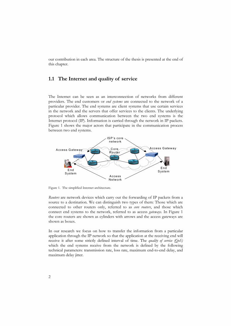
The Internet can be seen as an interconnection of networks from different providers. The end customers or end systems are connected to the network of a particular provider. The end systems are client systems that use certain services in the network and the servers that offer services to the clients. The underlying protocol which allows communication between the two end systems is the Internet protocol (IP). Information is carried through the network in IP packets. Figure 1 shows the major actors that participate in the communication process between two end systems.
Routers are network devices which carry out the forwarding of IP packets from a source to a destination. We can distinguish two types of them: Those which are connected to other routers only, referred to as core routers, and those which connect end systems to the network, referred to as access gateways. In Figure 1 the core routers are shown as cylinders with arrows and the access gateways are shown as boxes. In our research we focus on how to transfer the information from a particular application through the IP network so that the application at the receiving end will receive it after some strictly defined interval of time. The quality of service (QoS) which the end systems receive from the network is defined by the following technical parameters: transmission rate, loss rate, maximum end-to-end delay, and maximum delay jitter.
A ccess G ateway
E nd S ystem
End S ystem
A ccess Network
IS P ’s co re network
Core R outer
A ccess G ateway
Figure 1. The simplified Internet architecture.

3
The transmission rate is the number of data bits issued per second by an end system. The loss rate is a fraction of all IP packets of an end-to-end communication which might be lost in the network. The end-to-end delay is the time it takes for an IP packet to cross the network from a source to a destination. The end-to-end delay constitutes two components: the fixed delay and the variable delay. The fixed delay is the delay of the network links; it does not change with time. The variable delay is all other delays which the packet attain both in the network and in the end systems. It depends on the traffic load at a particular time. Delay jitter is the variance of the end-to-end delay. The maximum delay jitter is the bound on the delay variance, it is the difference between the maximum and minimum end-to-end delays. The bound on the delay jitter is an essential parameter for dimensioning playout buffers.
1.2 Service differentiation in the Internet
A major concept in the Internet today is to provide different levels of service for data traffic and real-time traffic. Quality of service differentiation in the network has been under intensive research during the last decade. The integrated services architecture [2], usually referred to as intserv, and differentiated services architecture [5], referred to as diffserv, are two approaches developed for the Internet. Regarding service differentiation these architectures differ in the following way. Intserv offers three service classes to the end systems: guaranteed, controlled load and best effort service. Diffserv offers two default classes of service to the end users: assured forwarding and expedited forwarding. Table 1 shows the characteristics of both architectures and the types of applications for which each class has been designed.

4
Table 1. Characteristics of service classes and intended applications.
Classes of service Characteristics Intended type of application Integrated
services Differentiated
services Delay Loss
Real-time applications with no tolerance to large delays and packet loss (inelastic). An example of such an application is a high quality video.
Guaranteed service
Not available
Small
Zero
Real-time applications with no tolerance to large delays and small tolerance to packet loss (adaptive). An example of such an application is voice over IP (VoIP).
Controlled load service
Expedited forwarding
Small
Small
Non-real time applications with no requirements on delay or loss rate (elastic). Examples of such applications are file transfer by FTP and web browsing.
Best effort service
Assured forwarding
Large
Large
A more technical description of these QoS architectures is presented in Section 1.4. It is important to highlight that the research work presented in this thesis is aimed at providing an appropriate service for inelastic applications with strict requirements on the delay of traffic and no tolerance to packet loss. Therefore we will concentrate on network mechanisms which provide QoS for this type of application.
1.3 Network mechanisms for QoS support
In order to guarantee absence of packet loss and strictly bounded delay for inelastic applications, the network should treat those connections separately from applications with other service requirements. In order to deploy these guarantees, routers need to reserve a part of the available link capacity for every connection with guarantees. When the necessary resources are available in the routers they are allocated to a particular connection. Finally a specific transmission should be applied to all data packets of this connection at every

5
router. In fact the above presented scenario is how the guaranteed service is deployed in the intserv architecture. From this scenario we may define two major mechanisms, which allow the network to provide guaranteed service to the end systems: the signaling protocol and the scheduling.
1.3.1 Quality of service signaling
QoS signaling is a sequence of messages issued by the end systems that delivers quality of service requirements of a connection to all routers on the path of the communication. In its simplest case, the operation of QoS signaling can be illustrated as shown in Figure 2.
An end system that wishes to transmit data with a certain QoS issues a reservation message specifying the parameters for the connection. When the reservation message arrives at a router, the router checks whether the available resources are sufficient to accommodate the incoming request. This procedure is called admission control. If a router does not have enough resources it drops the request, otherwise it registers it. In technical terms the router creates a state for the connection. Definition 1. State is a record in the internal database of a router, which defines the kind of service that should be provided for all packets of a particular connection. A reservation message that reaches the destination has passed admission control in all routers on the path. The destination then issues a confirmation message replying that the reservation was successfully completed and the sender end system may transmit its data. A more technical description of operation of signaling protocols as well as their classification is presented in Chapter 3.
Reserve (parameters)
End System A
Reserve (parameters)Reserve (parameters)
Reserve (parameters)
Reserve (parameters)Reserve (parameters)
Confirm (parameters) Confirm (parameters)
Confirm (parameters)Confirm (parameters) Confirm (parameters) Confirm (parameters)
End System B
Figure 2. A hop by hop signaling of QoS parameters.

6
1.3.2 The scheduling
In order to understand the scheduling, let us consider the internal structure of a router. A simplified router architecture is shown in Figure 3. In this figure we depict a router which has four input and output ports. We assume there are only two flows which traverse this router. One high priority flow enters the router at input port one and is destined to output port four. Another flow of the low priority enters the router at input two and is also destined to output four. Upon arrival at the output port, packets of the two flows are classified and placed in separate queues according to their priority. Now the task for the router is to provide an appropriate treatment for each of these two flows.
Definition 2. Scheduling is a mechanism in routers which coordinate the order of transmission of IP packets from different queues. Definition 3. A flow is constituted of all IP packets between two end systems. Later in the text, we will also discuss a set of individual flows which belong to one service class. We refer to this set of flows as an aggregate flow of a service class. All scheduling schemes can be classified as either work conserving or non-work conserving. In a work-conserving discipline, a server is never idle when there are packets to send. One simple example of a work conserving scheduling is a strict priority first-in-first-out (FIFO) discipline. Under this discipline packets of a higher priority will be transmitted on the link first and the lower priority packets will remain in the queue until the last high priority packet is sent. Another example of scheduling is weighted fair queuing. The procedure of this scheduling discipline is as follows: Every queue at an output port of a router is assigned a weight, this weight
Input ports O utput ports
2 input ports
SWIT
CH
Q ueue for low p riority flow from input 2
Q ueue for h igh p riority flow from input 1
Scheduler a t ou tput port 4
1
2
3
4
1
2
Fig. 3. Simplified router architecture.
7
corresponds to the share of the total transmission capacity of the outgoing link. Packets from each queue are then served at a rate depending on the weight of the corresponding queue. Another class of scheduling disciplines is non-work-conserving. In this type of scheduling every packet that arrives at the output buffer is assigned an eligibility time. The packet is held in the buffer until this time. Under these service disciplines, a packet is not sent even if it is waiting in a queue, but the time allocated for its transmission is not due. Examples of non-work conserving schedulers are Stop and Go, Earliest Due Date, Cell Spacing, and Hierarchical Round Robin. A detailed description of this class of service disciplines is given in Chapter 2. As stated in the beginning of this section, scheduling is the mechanism that enforces appropriate treatment of flows according to their QoS requirements. Therefore formal verification of QoS characteristics such as the delay bound or necessary buffer size to ensure absense of packet loss is an essential part of the development of any scheduling scheme. Analysis of the delay properties of scheduling algorithms has received much attention during the last decade. A technique, which permits this analysis is network calculus [36]. We will apply network calculus to calculate the delay bound in our service architecture in Chapter 2. Therefore, we need to introduce the basic concepts of the theory.
1.3.3 Introduction to network calculus
The theory is based on two fundamental concepts: The arrival curve of a flow and the service curve of a node. Definition 4. The arrival curve is a function that defines a bound on the arrival rate of a flow to a particular network node. One example of an arrival curve is a token bucket introduced first in [31]. This curve has the form brta += and is illustrated in Figure 4a. It means that a source may issue b bits of its traffic at once and over the long run it will not exceed the rate r b/s. In the scope of the intserv architecture, a combination of two token buckets is used to characterize a flow, in the terminology of intserv it is referred to as a TSpec (traffic specification). The TSpec describes a flow using four parameters (p, M, r, b). Where p is the peak rate, M is the maximum packet size, r is the sustainable rate, and b is the burst tolerance. The TSpec arrival curve has the form
( )brtMptTSpec ++= ,min and is shown in Figure 4b.

8
t
b
a [Bits] rt
pt
t
M
TSpec[bits]
b
rt
a. A single leaky bucket arrival curve. b. Intserv’s TSpec.
Figure 4. Example of arrival curves
Definition 5. The service curve is a function that defines a bound on the departure rate from a network node. In the case of the strict priority FIFO for example, the service curve for the highest priority queue has the form ( )+−= MTUCtσ as illustrated in Figure 5, where the notation ( ) ( )⋅=⋅ + ,0max and MTU is the maximum transfer unit. This service curve defines that data from the higher priority queue will be served at link speed C. Now with the definitions of the arrival and service curves we can compute a bound on the delay at a node and the size of a buffer, which is needed to avoid packet loss. The graphical solution for calculation of the delay bound and the size of the buffer for one flow with TSpec(p,M,r,b) passing through a router with SP FIFO scheduling is illustrated in Figure 6. In order to calculate the maximum delay D, we compute the maximum horizontal deviation between the service and the arrival curves. In order to calculate the buffer size B we compute the maximum vertical deviation between the two curves.
t
bits
MTU/C
Ct
t
B
MTU/C
D b
bitspt
rt
M
Ct
Figure 5. The service curve of SP FIFO. Figure 6. An example of the delay bound calculus.
9
1.4 A brief history of IP QoS: 1981 - 2003
The idea to provide certain applications with different types of services was conceived since the beginning of the Internet. RFC 791 [1] defines precedence marking of packets. Using this approach an application selects a relative priority or precedence for a packet. The routers along the transit path apply the appropriate forwarding behavior corresponding to the priority value within the packet’s header. With the appearance of network applications such as real time voice, which were not under consideration when the Internet was originally designed, it became clear that the traditional best effort service does not allow such applications to communicate with the appropriate quality. An attempt to provide real time applications with delay, jitter and zero packet loss guarantees was taken by the developers of a service architecture Tenet [8]. In response to the growing demand for multi-service Internet the integrated services architecture [2] was proposed. The time however showed that intserv is not suitable for large high-speed IP networks, as a result the differentiated services architecture [5] appeared in the end of the nineteen nineties. In the following sections we overview the three frameworks.
1.4.1 Tenet
The aim of Tenet was to provide strict guarantees on the end-to-end delay and delay jitter for real-time applications. In order to obtain such guarantees a real-time application needs to establish a real-time channel. During the channel establishment phase the application declares its delay requirements to all routers along a path to the destination. When receiving a request every router advertises its local delay bound which can be guaranteed for all packets of this channel in the router. Based on this data, the destination verifies whether the delay parameters satisfy the needs of the application. If the parameters conform, the destination permits the sender to start the data transmission. The quality of data transmission for the real time applications is ensured in this architecture by having non-work-conserving scheduling implemented in all routers, it is described in Chapter 2. The Tenet architecture remained in a stage of a prototype implementation without further development.
1.4.2 The integrated services architecture
The integrated services architecture defines three service classes: The controlled load service (CLS) [3], the guaranteed service (GS) [4] and the best effort service (BE). According to [3] the controlled load service is intended to support so called adaptive real-time applications, which are sensitive to overloaded conditions in the network. Each network node accepting a request for a
10
controlled-load service must ensure that adequate bandwidth and packet processing resources are available to handle the traffic specification requested by sources. The sources specify their traffic requirements using a TSpec characterization as described in Section 1.3.3. The admission of a flow must be accomplished through admission control. The signaling protocol of intserv is RSVP [11]. Flows using the CLS have no guarantees on the end-to-end delay. However, they get assurance of low packet loss probability. In other words, a flow using controlled load service will be provided with a service, which is equivalent to best effort under lightly loaded conditions. The guaranteed service [4] specifies that packets will arrive within a certain delivery time and will not be discarded due to queue overflows in the routers. The guaranteed service assumes that traffic of a guaranteed service flow satisfies its parameters as also specified by a TSpec. The end systems use the RSVP signaling protocol to declare their TSpec’s to routers. The per-flow scheduling shapes the traffic of each guaranteed service flow according to the reserved TSpec. This service is intended for a wide range of real-time applications with strict requirements on the end-to-end delay and no packet loss. Reading this section one could ask oneself with the intserv architecture implemented, why don’t we have support for inelastic applications in the Internet? The problem moves us back to 1992 – 1994 when intserv was being standardized. At that moment the technical base was not sufficient to handle a large number of individual states in routers. According to [39] the implementation of a packet classifier reported in 1992 allowed classification of only 256 individual connections (it was shown in 1999 that a classifier can handle 11000 connections at a speed 200 Mb/s [10]). Since the number of connections in a backbone network could be much larger than the number of connections that routers were able to process at that time, intserv received a reputation of not being a scalable architecture. Researchers moved towards development of a new architecture aiming at eliminating the complexity of intserv. As a result, in 1998 the differentiated services architecture was developed. Further development of the intserv architecture is in the scope of the IETF working group ISSLL (Integrated Services over Specific Link Layers) [9]. It has led to the extension of the operations of the intserv architecture. The resulting documents of the ISSLL working group, e.g. [12, 13], cover the issues of aggregation in RSVP and methods for interoperation of the intserv and diffserv architectures.
1.4.3 The differentiated services architecture
The differentiated services architecture [5] is based on a simple model where traffic entering a network is classified at the edges of the network and assigned to

11
different behavior aggregates (BA). The core routers provide separate treatment, called per-hop behavior (PHB), for packets of different BAs. Further development of this approach in [28] defines two default per-hop behaviours: Assured forwarding [6] and expedited forwarding [7]. The assured forwarding PHB (AF PHB) is designed for applications without any particular demand on the end-to-end delay. The only assurance these applications require is that their packets are forwarded with high probability assuming that the aggregate traffic from each source does not exceed the subscribed rate. However applications which use the AF PHB may exceed the subscribed rate, which will result in a higher loss probability in comparison to the case where the sources transmit their traffic with the subscribed rate. The expedited forwarding PHB (EF PHB) is designed for applications which require a service from the network with low packet loss, latency and jitter and with an assured end-to-end bandwidth. In other words, end systems which use the EF PHB should see the entire end-to-end connection as a “virtual leased line”. According to the specification of the EF PHB [7], one way to provide these QoS parameters to applications is to treat EF flows in all routers inside a diffserv domain as the highest priority flows. One can use a class-based scheduling (e.g. per-class weighted fair queuing) or a strict priority FIFO scheduling. As one can see in diffserv, the core routers only deal with aggregates of flows that belong to either one of the two classes. This implies much simpler scheduling solutions, where routers coordinate transmissions between fewer queues. Despite the efficiency of processing and high scalability, diffserv has failed to provide end users with strict specification of service performance achieved in every class as was specified in intserv (this fact is also reflected in Table 1). Moreover it eliminated a possibility for users to dynamically change their service requirements, which was possible by using RSVP in intserv. In diffserv, a user signs a contract, called the service level agreement (SLA), with the service provider and it remains unchanged until the user signs a new SLA.
1.5 Motivation for the development of a new architecture
As was shown in the previous section from the point of view of performance and scalability, intserv appeared to be not suitable for high-speed IP networks. The limiting factor of this architecture is the number of individual connections that can be supported. The diffserv architecture however, is free of limitations since a router serves all flows of a behavior aggregate together. The high scalability of the diffserv is accomplished by separating the operations performed
12
at the borders of the network from those performed in the core. There is alas an inflexibility in this approach, namely a service level agreement (SLA) does not allow the end user to dynamically change the service requirements, for example the maximum allowed bit rate. The limited scalability of the intserv approach and lack of dynamic resource allocation in the diffserv architecture have motivated us to develop a new service architecture. The main principles of our QoS architecture were proposed by Karlsson and Orava in [51]. The work states that applications with different QoS requirements can be supported with a small set of basic network services. The simplicity of services will make fast router implementations feasible. In our architecture we use the strengths of the intserv and diffserv architectures. We define service classes as in the intserv architecture and use the idea of aggregate scheduling from diffserv. We use the idea of explicit resource reservation as in intserv, replacing heavy weight RSVP with our lightweight signaling protocol.
1.6 The framework of a new service architecture
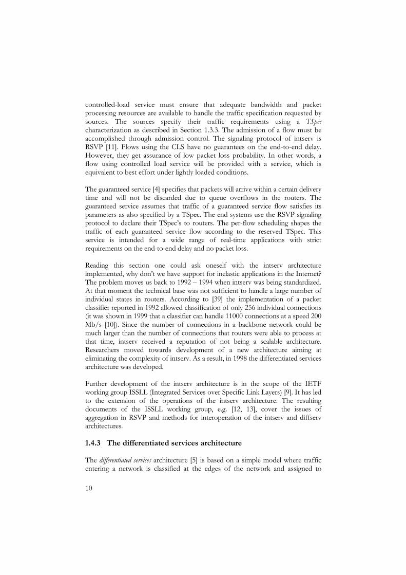
We are developing a service architecture consisting of three quality classes, as illustrated in Figure 7. The guaranteed service (GS) class provides deterministic guarantees namely constant throughput, no packet loss due to queue overflows in routers and a tightly bounded delay. Flows of the controlled load service (CLS) class have bounded packet loss and limited delay. The third traffic class is the customary best effort (BE). The flows of this class have no guarantees; they obtain the leftover capacity in the routers and may be discarded during congestion. Both the guaranteed service and controlled load service are allocated restricted shares of the link capacity so that the BE traffic does not get starved. Best effort traffic uses the unused portions of the capacity reserved for CLS and GS traffic.
q_gs
q_cls
q_be Separate queues
Scheduling
CGS
CCLS
CBE
Capacity
Clink
Time
CBE
CBE
CCLS
CGS
Figure 7. The service architecture.

13
Upon arrival all packets are sorted according to the service class and placed in separate queues. The work which is reflected in this Licentiate thesis concerns only the guaranteed service class, therefore we only describe the mechanisms for implementing this service. The framework for the development of the guaranteed service class consists of two major parts: The analysis of a special scheduling algorithm and the design and analysis of a new simple signaling protocol. The important assumption on which the design of the signaling protocol and scheduling algorithm are based is the additivity of the reservation state. Definition 6. The reserved rate of an outgoing link of a router is additive when it equals the sum of the incoming rates for the link. Router three in Figure 8 accepts the reservation for two GS connections with rates GS_rate1 and GS_rate2. After the reservation is made the router relies on the sources that their total peak rate on the outgoing link is not higher than the sum of individual peak rates.
GS_rate1
GS_rate2
GS_rate=GS_rate1+GS_rate2
Router 3
Router 1
Router 2
Figure 8. Additivity of the outgoing reservation state.
1.6.1 Packet scheduling in routers
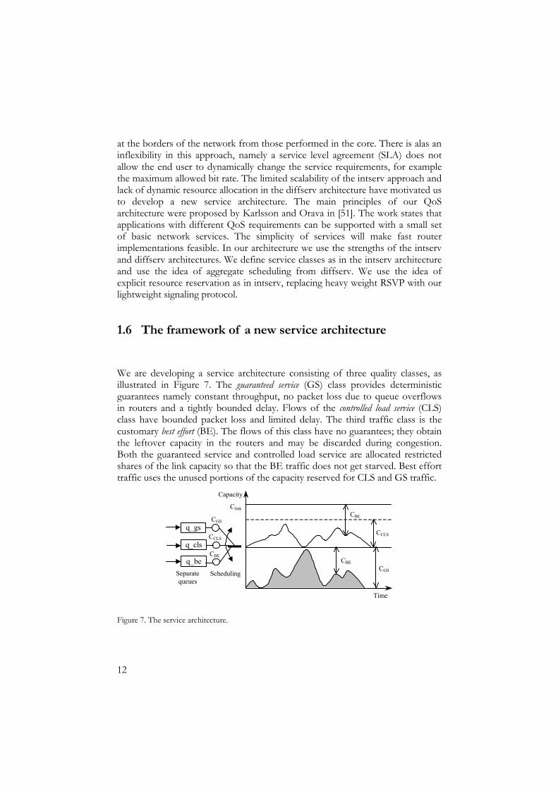
In order to satisfy the properties of our service model, a router needs a scheduling algorithm. This is to enforce additivity of the reservation state and to ensure absence of packet loss for the GS traffic in the network. The scheduling algorithm which was initially proposed in [52] ensures the above conditions for guaranteed service flows. It works with variable length packets up to a maximum transfer unit on a link. The algorithm prevents starvation of the best effort traffic. The router model that we are considering for the analysis defines a cascade of schedulers at the output port, as shown in Figure 9. In the first stage of the cascade we have a set of schedulers that are responsible for smoothing out the incoming flow aggregate from a particular input port directed to the output port. A scheduler in the second stage interleaves packets from different input ports so that additivity of the outgoing data rate is preserved and the lower priority traffic is not blocked.
14
n-1 input ports
SWIT
CH
ρρρρ1,n
ρρρρ2,n
ρρρρn-1,nρρρρ n
output portn
First stage of schedulers
Output scheduler of the second
stage
q_gs
q_be
Figure 9. Router model for guaranteed service flows.
The scheduling rule for the output scheduler in the second stage is straightforward. The scheduler will serve one or more packets from the GS queue (q_gs in Figure 9), and it will schedule an idle period that is long enough to preserve the outgoing reserved rate of the GS traffic. During the idle period, it will serve packets from both the CLS and BE classes. The number of GS packets served back to back at link speed is called a GS burst. The reservation ratio of the output port in a router is defined as
GSBurstIdleGSBurst
+=ρ .
(1)
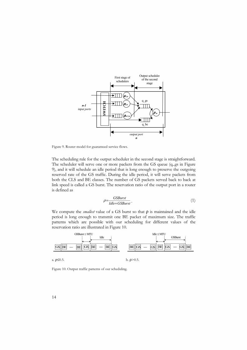
We compute the smallest value of a GS burst so that ρ is maintained and the idle period is long enough to transmit one BE packet of maximum size. The traffic patterns which are possible with our scheduling for different values of the reservation ratio are illustrated in Figure 10.
BE BEBE GS GS
GSBurst ≤ MTU Idle
GS BE
GS GS GSBE BE
Idle ≤ MTUGSBurst
BE GS
a. ρ≤0.5. b. ρ>0.5.
Figure 10. Output traffic patterns of our scheduling.
15
The schedulers in the first stage are the same type as the output scheduler except that during the GS idle period they do not serve any traffic.
1.6.2 The signaling protocol
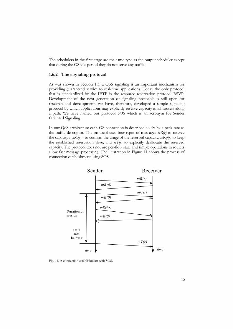
As was shown in Section 1.3, a QoS signaling is an important mechanism for providing guaranteed service to real-time applications. Today the only protocol that is standardized by the IETF is the resource reservation protocol RSVP. Development of the next generation of signaling protocols is still open for research and development. We have, therefore, developed a simple signaling protocol by which applications may explicitly reserve capacity in all routers along a path. We have named our protocol SOS which is an acronym for Sender Oriented Signaling. In our QoS architecture each GS connection is described solely by a peak rate as the traffic descriptor. The protocol uses four types of messages mR(r) to reserve the capacity r, mC(r) - to confirm the usage of the reserved capacity, mRef(r) to keep the established reservation alive, and mT(r) to explicitly deallocate the reserved capacity. The protocol does not use per-flow state and simple operations in routers allow fast message processing. The illustration in Figure 11 shows the process of connection establishment using SOS.
Sender Receiver
Duration of session
mT(r)
mC(r)
mR(0)mR(r)
Data rate
below r
time time
mR(0)
mRef(r)
mR(0)
Fig. 11. A connection establishment with SOS.

16
1.7 My contribution
The work reflected in this Licentiate thesis concerns only the guaranteed service class of the service architecture presented in Section 1.6. My contribution to the development of the network support for the guaranteed service consists of two major parts: The analysis of the scheduling algorithm presented in Section 1.6.1 and the design and analysis of a new signaling protocol introduced in Section 1.6.2. My contribution to the area of scheduling is essentially the development of the two-stage scheduling architecture and the formal and experimental analyses of the delay properties of this approach. The results of my work are presented in Chapter 2. I have implemented the scheduling algorithm in the routers for the network simulator ns-2 [58] and performed a series of experiments. The aim of the experiments was to compare QoS parameters attained with our scheduling to the same conditions of the expedited forwarding PHB of diffserv. According to the specification of the EF PHB [7] a method to provide the necessary QoS for the delay-sensitive applications is to treat EF flows as the highest priority flows. One can implement this using a class-based scheduling (e.g. per-class weighted fair queuing) or a strict priority FIFO scheduler. I performed a series of simulations in order to compare the performance of our scheduling algorithm to the same conditions in SP FIFO and WFQ scheduling. My studies of the delay properties of the GS traffic show that our scheduling introduces a delay jitter which is smaller than the delay jitter under both SP FIFO and WFQ. I calculated the delay bound for the GS traffic attained with our scheduling and the size of buffers needed in routers to ensure absence of packet loss for the GS traffic. I showed both analytically and experimentally that the maximum end-to-end delay under usage of our scheduling is acceptable for real-time applications. A part of the work described in Chapter 2 was published in the proceedings of the Seventh International Workshop on Protocols for High Speed Networks, PfHSN 2002, [56]. As a result of the work on the development of the signaling protocol (introduced in Section 1.6.2), I have completed a specification of the protocol for unicast communication. Whilst designing the operation of the protocol I considered both the networks with stable routes and networks where routes may change. I have developed two fault handling mechanisms. These make SOS tolerant to losses of all types of signaling messages. I have implemented the protocol in the end systems and routers for the network simulator ns-2 and run a series of simulations to evaluate the performance of our protocol. The simulations performed on a 500 MHz Pentium III processor have shown that routers could process up to 700,000 signaling messages per second. I have also developed a mechanism that can handle re-routing of GS packets. The results of the work related to operation of SOS in
17
networks with stable routes were published in the proceedings of the Third International Workshop on Quality of Future Internet Services, QofIS 2002 [57]. This paper was given the “Best Ph.D. Student Paper Award”.
1.8 The structure of this thesis
The thesis is organized as follows: • In Chapter 2 a detailed description of the scheduling architecture is
presented. We begin this chapter with a survey of the related work in the areas of scheduling algorithms and methods of their analyses. We proceed with a description of the proposed scheduling algorithm. We then describe the router architecture for supporting our scheduling. After that, using network calculus we calculate the delay bound which the guaranteed service flows attain. Finally, we present results of experimental studies on delay, link utilization and the fairness properties of our scheduling.
• In Chapter 3 we describe the details of the operation in our signaling
protocol and present its experimental performance evaluation. We begin with a brief introduction to signaling protocols and their classification. We then describe the related work in the area of signaling protocols. We proceed with a description of the operation of our signaling protocol in the end systems and routers. We elaborate further on the encoding scheme for signaling messages in the current format of the IP packet header. We then describe the fault handling operation of our protocol in the case of loss of signaling messages and in the case of rerouting. Finally we focus on the experimental studies of the protocol performance.
• In Chapter 4 we consider the issues of application of the guaranteed
service for resource provisioning in the backbone network. In our vision of the future Internet, the designed guaranteed service can be used as the default service class in the backbone network.
• In Chapter 5 we summarize the work described in this thesis. We
conclude by presenting ideas for future research.


19
CHAPTER 2. SCHEDULING FOR A SIMPLIFIED
GUARANTEED SERVICE
Scheduling is a mechanism in routers that ensures the necessary QoS characteristics for flows of packets. In the case of our service architecture we need a scheduling algorithm in the routers to enforce additivity of the reservation state and to ensure zero packet loss for the guaranteed service traffic. The scheduling algorithm, which was initially proposed in [52], ensures aforementioned conditions for guaranteed service flows. In this thesis, we will refer to this algorithm as SGS, which is an acronym for ‘scheduling for a simplified guaranteed service’. The algorithm has the following properties: • It deals with variable length packets up to some maximum transfer unit. • The algorithm prevents starvation of the lower priority traffic. • The computed buffer space for the GS traffic is sufficient to avoid packet
loss, taking into account the worst arrival pattern.
My contribution to this area is essentially the development of SGS schedulers for the output ports of the routers and its formal and experimental analyses. Recall that in our service architecture we define three service classes: The guaranteed service, controlled load service and best effort service. Since the guaranteed service and controlled load service classes are isolated from each other to simplify the description of the scheduling algorithm, we will consider only interaction between the GS and best effort service class. We begin this chapter (Section 2.1) with a survey of the related work in areas of scheduling algorithms and methods of their analyses. In Section 2.2 we present a description of the proposed scheduling algorithm. The router architecture for supporting our scheduling is described in Section 2.3. In Section 2.4 using network calculus we calculate the delay bound for the guaranteed service flows. We present results of experimental studies of the delay, link utilization, and fairness properties in Section 2.5. We summarize the discussion of the scheduling in Section 2.6.
20
2.1 Related work
The differentiation of services in the Internet highlights the problem of the traditional first-in-first-out scheduling algorithm. It was shown in [36, 46 and 48] that pure FIFO service discipline does not provide any control over flows and cannot ensure QoS levels for end users. The development of the scheduling algorithms for providing packet flows with firm QoS requirements began from theoretical studies of the properties of packet flows, which were done by Cruz [31, 32]. He establishes a method to calculate the end-to-end delay bound for a flow and the size of a buffer needed in each node to ensure loss free service for that flow. The author investigates these parameters for a single node case in [31] and for the case of a network of nodes in [32]. Cruz’s theory assumes that each node in the network shapes the traffic of an individual flow so that it satisfies the initially negotiated characterization. The theoretical work of Cruz was further studied and extended in [[34, 35 and 36]. The scheduling algorithm proposed in [31], Generalized Processor Sharing (GPS), assumes a fluid model of traffic where the traffic is seen as a continuous stream of bits. Its basic concept is that an individual flow does not exceed its pre-negotiated transmission rate and the number of bits transmitted back to back is limited so that other flows obtain fair service. Although Cruz’s theory is able to compute service parameters in this scenario, the fluid model of traffic that is used by GPS, is an idealized assumption; in reality we have packetized transmission. The work of Golestani, Zhang, and others based on the results of Cruz propose service disciplines that adapt GPS to the packetized case. Examples of such schemes are Self-Clocked Fair Queuing (SFQ) [37] and Weighted Fair Queuing (WFQ) [38]. A good overview of the existing approximation of GPS is given in [39]. The above mentioned GPS scheme and its packetized versions belong to the class of work-conserving scheduling disciplines. In a work-conserving discipline a scheduler is never idle when there is a packet waiting to be sent. Another class of scheduling disciplines is the non-work-conserving class. In this type of scheduling every packet that arrives at the output buffer is assigned an eligibility time. The packet is held in the buffer until this time. Thus, the server may remain idle although there is work (packets) to be served. Since the scheduling algorithm in our architecture belongs to the non-work conserving disciplines we describe the related work in this area in more detail.

21
2.1.1 Non-work-conserving scheduling algorithms
A good overview of the general classes of non-work-conserving scheduling disciplines is given in [40]. The paper defines two types of scheduling algorithms: The rate-jitter controllers and delay-jitter controllers. Examples of some schedulers which use the delay-jitter control policy are Stop and Go [41] and Earliest Due Date (EDD) [39]. Examples of the schedulers which use the rate-jitter control policy are Cell Spacing [43] and Hierarchical Round Robin [42]. The difference between the two classes of non-work-conserving scheduling approaches is described below. The delay jitter controllers appeared in the scope of the Tenet architecture [8]. The aim of Tenet was to provide strict guarantees on the end-to-end delay and delay jitter for real-time applications. In order to obtain such guarantees, a real-time application needs to establish a real-time channel. During the channel establishment phase, the application declares its delay requirements to all routers along a path to the destination. When receiving a request, every router advertises its local delay bound that it can guarantee for all packets of this channel. Therefore, when the channel-establishment message arrives at the destination, it contains the delay bounds for all routers along the path of the connection. Based on this data the destination verifies whether the parameters satisfy the needs of the application. If the parameters conform to the needs, the destination replies with an accept message, which follows the same path in the reverse direction towards the source. All routers react to this message by registering the deadline time for the packets of this connection. When the accept message arrives at the source, it contains the transmission deadline for the first router. The deadline based scheduling works as follows: Before sending packet P, every router computes d, the difference between the deadline of this packet in this router and its actual transmission time. This value is then encoded in the packet’s header and is transmitted to the next downstream router. If a packet is transmitted before its deadline the delay jitter for packets of a particular channel increases. The downstream router assigns the time when packet P is eligible for transmission taking uniformly the value from the interval [a+d-∆, max(Deadline(P), a+d)], where a is the arrival time of the packet and ∆ is an internal constant of the scheduler accounting for possible inaccuracy of computation of d. By doing this operation the next downstream router eliminates the jitter in a particular channel introduced by the upstream routers. The implementation of this type of scheduling requires modification of the transmission protocol since all routers have to transmit the value d in the options field of the header of every IP packet. In addition, the scheduling requires computation of the eligibility times for every packet.

22
The difference of the rate-jitter schedulers from the delay-jitter schedulers is in how routers compute the eligibility times for packets. In a rate-jitter scheduling algorithm the eligibility time for a packet is computed in a particular router with respect to the departure time of the previous packet of the same flow from the same router. Both types of non-work-conserving schedulers were developed to provide QoS for individual flows.
2.1.2 Work on the analysis of scheduling in the scope of differentiated services framework
The development of the scheduling algorithms has received much attention when the integrated services architecture was proposed. The research efforts were towards ensuring QoS levels for individual flows. Analysis of the aggregate scheduling became a challenge when the differentiated services architecture appeared. In fact, there are no specially developed scheduling algorithms for the diffserv architecture. The work on aggregate scheduling concerns an analysis of the delay properties of the existing scheduling schemes when used to schedule flow aggregates. We can distinguish two directions of the work in this area: The study of topological aggregation and the study of per traffic class aggregation. Topological aggregation means that flows, which should be aggregated, must share the same path over the network. An approach towards topological flow aggregation in the integrated services architecture is described in [62]. The ingress nodes at the aggregation domain intercept all individual reservation requests and aggregate them based on the common egress point from the network. An aggregation domain is a network which supports the differentiated services architecture. The ingress routers shape all flows which follow the same path according to their aggregated traffic specification. It was shown in [62] that this type of aggregation might drastically decrease the complexity of the intserv architecture whilst still providing tight delay bounds on individual flows. Another type of aggregation that is used in differentiated services architecture is traffic class based. Since in our service architecture we perform per traffic class aggregation, we will consider the related work in this area in more detail. The work which has been done on traffic class based approach of flow aggregation is given in [36, 45 and 46]. These publications give a methodology for an analysis of the aggregated flows. The work presents calculation of the delay bound for general topology networks where all routers use a strict priority FIFO scheduling at the output. The calculated delay bound is a function of the number of routers traversed by a flow and the maximum reservation ratio of low delay traffic on the links. A reservation ratio in this context is a share of the total link capacity allocated to the high priority and low delay traffic. However, in the case of SP FIFO the calculated delay bound is valid only for very small values of the reservation ratio.
23
This is due to the specific properties of SP FIFO scheduling where the creation of a burst of several packets cannot be controlled in the network. The work in [48] elaborates reasons for the instability of the FIFO scheduling algorithm. The main conclusion of [45 and 46] is that in order to obtain a delay bound with pure output scheduling, one either has to restrict the topology of the network or to make the reservation ratio for high priority traffic very small (in order of several percent of the total link capacity).
2.2 SGS: A packet scheduling algorithm for guaranteed service flows
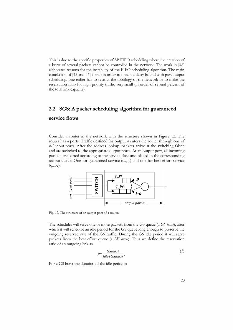
Consider a router in the network with the structure shown in Figure 12. The router has n ports. Traffic destined for output n enters the router through one of n-1 input ports. After the address lookup, packets arrive at the switching fabric and are switched to the appropriate output ports. At an output port, all incoming packets are sorted according to the service class and placed in the corresponding output queue: One for guaranteed service (q_gs) and one for best effort service (q_be).
q_gs
q_be
SWIT
CH
ρρρρ
1-ρρρρ
n-1
inpu
t por
ts
output port n
Fig. 12. The structure of an output port of a router.
The scheduler will serve one or more packets from the GS queue (a GS burst), after which it will schedule an idle period for the GS queue long enough to preserve the outgoing reserved rate of the GS traffic. During the GS idle period it will serve packets from the best effort queue (a BE burst). Thus we define the reservation ratio of an outgoing link as
GSBurstIdleGSBurst
+=ρ .
(2)
For a GS burst the duration of the idle period is

24
GSBurstIdle ρρ−
=1
. (3)
Note that with increasing ρ (up to 1) the idle period for GS queue tends to 0. Under such circumstances the BE traffic will be blocked. Thus, we compute the smallest length of the GS burst so that ρ is maintained and the following idle period is sufficiently long to transmit one BE packet up to the maximum size MTU. Thus,
the size of the burst of the guaranteed service traffic is at most MTUρ
ρ−1
bytes
for ρ > 0.5 and at most MTU for ρ ≤ 0.5. The pseudo code of the scheduling algorithm is shown in Appendix 1. The schematic in Figure 13 shows outgoing traffic patterns generated by our scheduling algorithm. Note that the proposed scheduling scheme is non-work-conserving only with respect to GS packets. Best effort traffic receives the remaining capacity not used by the GS class.
BE BEBE GS GS
GSBurst ≤ MTU Idle
GS BE
GS GS GSBE BE
Idle ≤ MTUGSBurst
BE GS
a. ρ ≤ 0.5. b. ρ > 0.5.
Figure 13. The outgoing traffic patterns in our scheduling algorithm.
In fact the structure of a router depicted in Figure 12 where our scheduling is implemented only at the output has a drawback that it cannot prevent the creation of a burst of packets within an individual flow. In the next section we illustrate the burst creation process and show that when performing aggregate scheduling only at the output of a router it is very hard to quantify the burst.
2.2.1 The process of burst creation using pure output scheduling
Consider the first core router in a path which connects the number of access gateways to other core routers as shown in Figure 14. Recall that in our architecture the access gateways perform per-flow scheduling and shape the traffic of individual flows according to their reservations. Assume all core routers have the architecture depicted in Figure 12. Let us pick input port one of router one at which traffic from access gateway one arrives.

25
In Figure 15a we have an aggregate flow of ten packets per second (pps), observed at the considered input of router one during two seconds. The aggregate consists of ten individual connections, each with a rate of one pps. All the connections are smooth. Now, consider the possibilities of the arrival of a part of the aggregate with a total rate of five pps to the output port two of this router. The best case for the corresponding queue will be when the aggregate of five pps is smooth. This will occur when connections a,c,e,g,i are destined to port two (Figure 15b), but it could also occur that the five pps aggregate will consist of flows a,b,c,d,e (Figure 15c).
hc b a j ig f e d g f e d ch i j a b
1 second
c a ig e g e c i a
1 second
c b a e d e d c a b
1 second
Time, future
a)
b)
c)
Time, future
Time, future
Figure 15. The possibilities of arrival of the five pps aggregate.
In order to show the process of a burst creation let us follow an example. Let us consider a network as depicted in Figure 16. User A has established a GS connection with user B, denote this connection as e. The rate of connection e is one pps. On the path towards the destination there are h routers with four ports each. The capacity ten pps of the outgoing link is distributed in every router as follows: One pps is reserved for port a, four pps is reserved for port x and five pps is reserved for port y. The traffic from inputs x and y of every router shares the outgoing link (z to a) with connection e and then exits in the next downstream router. Assume that the aggregate flow from the input port x consists of four one-pps connections x1,x,2,x3,x4 and the aggregate from the input port y consists of five one-pps connections y1,y2,y3,y4,y5. Assume as well that the sequence of packets in these two aggregates is as depicted in Figure 15c. Assume also that flow e always interacts with the last packets of the connections from ports x and y. This
A ccess gatew ay 1
R ou ter 1
R outer 2
R outer 3
1 2
3
Figure 14. A network topology for the definition of a burst.

26
means that the ports x and y remain idle forever after the transmission of four and five packets respectively.
Let us consider the first two packets of connection e arriving at router one. Assume that the aggregates from inputs x and y of router one arrive as is shown in Figure 17.
x4 x3 x1 x2
y5 y4 y3 y1 y2
x4 e y5 e y4 x3 y3 x2 y2 y1 x1
First packet of connection e delayed
for five packet transmission times
Transmission of packets from output z
Arrival of aggregate x1,x2,x3,x4 at the queue of
output z
Arrival of aggregate y1,y2,y3,y4,y5 at the queue
of output z
e e
1 second
Arrival of flow e at the queue of output z
Time, future
Time, future
Time, future
Time, future
Figure 17. The multiplexing of packets in the output z of router one.
As a result of the multiplexing at output z the first packet of connection e will be delayed for five packet transmission times. Let now connection e arrives at the output queue z of router two. The interaction with the flows from ports x and y of router two is shown in Figure 18. The multiplexing in the second router results in the creation of a burst of two packets for connection e.
Access gateway 1 Access
gateway 2 Router 1 Router 2 Router h
x y x y x y
Flow e
User A
User B a z a z a z
Net 1 Net 2 Net 3
x1,x2,x3,x4 to net 2
y1,y2,y3,y4,y5to net 2
Figure 16. A network topology for the discovery of the worst case burst.

27
x4 x3 x1 x2
y5 y4 y3 y1 y2
x4 e e y5 y4 x3 y3 x2 y2 y1 x1
First packet of connection e delayed
for another five packet transmission times
Transmission of packets from output z
Arrival of subaggregate a,b,c,d,e at the queue of
output z
Arrival of subaggregate x1,x2,x3,x4,x5 at the queue
of output z
e e
1 second
Arrival of flow e at the queue of output z e
e
Time, future
Time, future
Time, future
Time, future
Figure 18. The multiplexing of packets in the output z of router two.
Assume now that in router three the cross-traffic from inputs x and y is represented by flows with two packets burst as shown in Figure 19.
x4 x4 x3 x3 x2 x2 x1 x1
y4y5 y5 y4 y3 y3 y2 y2 y1 y1
x2y4 x3 y3 x3 y3y5 x4 y4 x4 y2 x2 y2 x1 y1 y5e e y1 x1
Two first packets of connection e delayed
for nine packet transmission times
Transmission of packets from output z
Arrival of subaggregate x1,x2,x3,x4 with two
packets burst at the queue of output z
Arrival of subaggregate y1,y2,y3,y4,y5 with two
packets burst at the queue of output z
e e
1 second
Arrival of flow e at the queue of output z
e
e
Time, future
Time, future
Time, future
Time, future
Figure 19. The multiplexing of packets in the output z of router three.
The burst of three packets is created just after one router. In general the process of burst creation is a non-linear function of the number of routers on the path of a flow [36]. We can observe that the first time shift of the first packet of connection e will not happen if all three input ports of the first router would shape the arriving aggregates according to their reservation rates before entering the output buffer. In this case flow e will maintain its arrival pattern.

28
2.3 Modification to the structure of output ports in routers
As was shown in the previous section pure output scheduling has the drawback that it cannot prevent the creation of a burst of an individual flow. By performing aggregate scheduling only at the output of a router, it is very hard to quantify the process of burst creation and therefore to compute the delay bound. Whilst developing the scheduling architecture for our guaranteed service we accounted for this problem by inserting per-input shapers before the queue of the output scheduler.
2.3.1 Per-input shapers and their properties
We add n-1 shapers at each output port as shown in Figure 20. Each shaper is responsible for smoothing an aggregate directed to a particular output port. We denote the shaper that smoothes traffic from input port i to output port j as the (i,j)-shaper. The shaper here is the same scheduler as described in Section 2.2 with the exception that it schedules idle periods instead of BE bursts. Each shaper forces the incoming subaggregate to satisfy its reserved peak rate. After passing the shaper the traffic from a particular input port arrives at the output scheduler where it is multiplexed with traffic from other inputs. The output scheduler also provides a fair service to the best effort traffic as described in Section 2.2.
n-1 input ports
SWIT
CH
ρρρρ1,n
ρρρρ2,n
ρρρρn-1,n
ρρρρ n
output portn
Figure 20. The schematic of the modified output port for supporting guaranteed service.
29
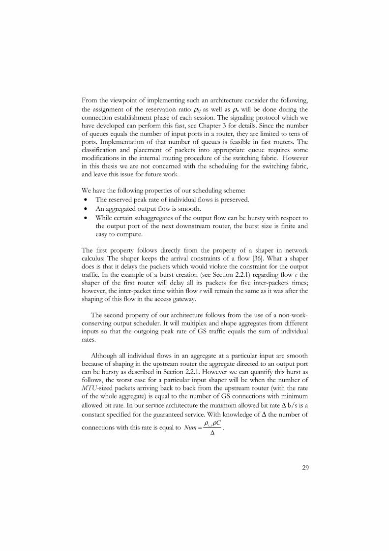
From the viewpoint of implementing such an architecture consider the following, the assignment of the reservation ratio ρi,j as well as ρn will be done during the connection establishment phase of each session. The signaling protocol which we have developed can perform this fast, see Chapter 3 for details. Since the number of queues equals the number of input ports in a router, they are limited to tens of ports. Implementation of that number of queues is feasible in fast routers. The classification and placement of packets into appropriate queue requires some modifications in the internal routing procedure of the switching fabric. However in this thesis we are not concerned with the scheduling for the switching fabric, and leave this issue for future work. We have the following properties of our scheduling scheme: • The reserved peak rate of individual flows is preserved. • An aggregated output flow is smooth. • While certain subaggregates of the output flow can be bursty with respect to
the output port of the next downstream router, the burst size is finite and easy to compute.
The first property follows directly from the property of a shaper in network calculus: The shaper keeps the arrival constraints of a flow [36]. What a shaper does is that it delays the packets which would violate the constraint for the output traffic. In the example of a burst creation (see Section 2.2.1) regarding flow e the shaper of the first router will delay all its packets for five inter-packets times; however, the inter-packet time within flow e will remain the same as it was after the shaping of this flow in the access gateway.
The second property of our architecture follows from the use of a non-work-conserving output scheduler. It will multiplex and shape aggregates from different inputs so that the outgoing peak rate of GS traffic equals the sum of individual rates.
Although all individual flows in an aggregate at a particular input are smooth
because of shaping in the upstream router the aggregate directed to an output port can be bursty as described in Section 2.2.1. However we can quantify this burst as follows, the worst case for a particular input shaper will be when the number of MTU-sized packets arriving back to back from the upstream router (with the rate of the whole aggregate) is equal to the number of GS connections with minimum allowed bit rate. In our service architecture the minimum allowed bit rate ∆ b/s is a constant specified for the guaranteed service. With knowledge of ∆ the number of
connections with this rate is equal to ∆
=C
Num ji ρρ , .
30
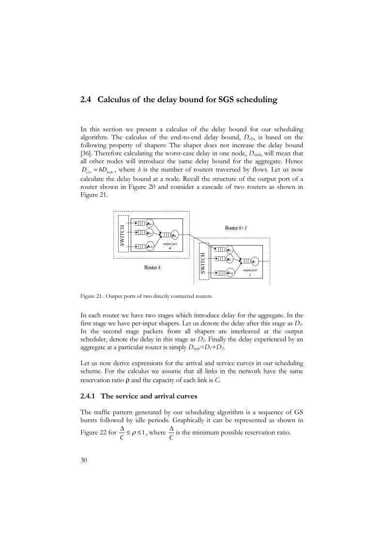
2.4 Calculus of the delay bound for SGS scheduling
In this section we present a calculus of the delay bound for our scheduling algorithm. The calculus of the end-to-end delay bound, De2e, is based on the following property of shapers: The shaper does not increase the delay bound [36]. Therefore calculating the worst-case delay in one node, Dnode, will mean that all other nodes will introduce the same delay bound for the aggregate. Hence
nodeee hDD =2 , where h is the number of routers traversed by flows. Let us now calculate the delay bound at a node. Recall the structure of the output port of a router shown in Figure 20 and consider a cascade of two routers as shown in Figure 21.
SW
ITC
H
SW
ITC
H
ρρρρ1,j
ρρρρ2,j
ρρρρn-1,j
ρρρρ j
output portj
ρρρρ1,n
ρρρρ2,n
ρρρρn-1,n
ρρρρ n
output portn
Router k
Router k+1
Figure 21. Output ports of two directly connected routers.
In each router we have two stages which introduce delay for the aggregate. In the first stage we have per-input shapers. Let us denote the delay after this stage as D1. In the second stage packets from all shapers are interleaved at the output scheduler, denote the delay in this stage as D2. Finally the delay experienced by an aggregate at a particular router is simply Dnode=D1+D2. Let us now derive expressions for the arrival and service curves in our scheduling scheme. For the calculus we assume that all links in the network have the same reservation ratio ρ and the capacity of each link is C.
2.4.1 The service and arrival curves
The traffic pattern generated by our scheduling algorithm is a sequence of GS bursts followed by idle periods. Graphically it can be represented as shown in
Figure 22 for 1≤≤∆ ρC
, where C∆ is the minimum possible reservation ratio.

31
Ct
t
GS
Cumulative service
σ(t)=min(Ct, ρCt+GS(1-ρ)) GS(1-ρ)
Slope=ρC
Figure 22. Service curve for the aggregate 1≤≤∆ ρC
, σ(t) is a bound on service curve of the
aggregate, GS is the length of the GS burst..
Depending on the value of the reservation ratio ρ, the service curve of the output scheduler for the aggregate can be stated as:
( ) ( ))1(,min ρρσ −+= GSCtCttout . (4)
As is stated in Section 2.2, the length of the GS burst depends on the value of ρ and is
=
<≤
−
≤≤∆
=
1,0
15.0,1
5.0,
ρ
ρρ
ρ
ρ
MTU
CMTU
GS .
(5)
Recall the cascade of two routers and consider the shaper (i,j) in router k+1. The shaper smoothes out an aggregate from input port i directed to output port j. Since in our architecture the shaper (i,j) is the same kind of scheduler as in the output case a service curve for the subaggregate in the shaper (i,j) is
( ) )1( ,,, ρρρρσ jijiji MTUCtt −+= ,
(6)
where ρi,j is the reservation ratio of shaper (i,j); note that GS burst is one MTU in this stage for all reservation ratios.

32
In Section 2.3.1 we quantified the worst case burst which can arrive to the shaper
as the number of connections with minimum allowed rates ∆
=C
Num ji ρρ , .
The arrival process of the subaggregate entering the shaper (i,j) is bounded by a curve which is the minimum between the arrival curve of the whole aggregate arriving at input i and the arrival curve that describes the subaggregate. Since the output scheduler is a shaper, then according to the definition of a shaper [36]: The arrival curve of the whole aggregate equals the service curve σout of the output scheduler in router k.
( ) ( )( )bCttta jioutji ′+= ρρσ ,, ,min .
(7)
The burst parameter b′ in (7) depends on ρi,j , the share of the outgoing capacity reserved from a particular input port. Namely, if the number of connections with minimum rate is smaller than the number of packets in the GS burst of the aggregate as shown in Figure 23, then NumMTU × bits may arrive at link speed. Otherwise, if the number of connections is larger than the number of packets in the GS burst, NumMTU × bits will arrive with the rate of the aggregate as shown in Figure 24.
ai,j(t)
Ct
t
Cumulative arrivals
σout(t)=min(Ct, ρCt+MTUρ)
MTUρ
MTU × Num
b’
ρρ−
=1
MTUGS
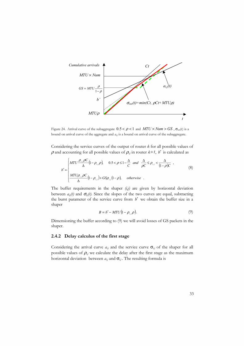
Figure 23. Arrival curve of the subaggregate 15.0 << ρ and GSNumMTU ≤× , σout(t) is a bound on arrival curve of the aggregate and ai,j is a bound on arrival curve of the subaggregate.
33
ai,j(t)
Ct
t
Cumulative arrivals
σout(t)=min(Ct, ρCt+MTUρ)
MTUρ
MTU × Num
b’
ρρ−
=1
MTUGS
Figure 24. Arrival curve of the subaggregate 15.0 << ρ and GSNumMTU >× , σout(t) is a bound on arrival curve of the aggregate and ai,j is a bound on arrival curve of the subaggregate.
Considering the service curves of the output of router k for all possible values of ρ and accounting for all possible values of ρi,j in router k+1, b′ is calculated as
( ) ( )
( ) ( )
−+−∆
−∆<≤∆∆−≤<−
∆=′
.,11
,1
15.0,1
,,,
,,,
otherwiseGSCMTU
CCand
CC
MTU
b
jijiji
jijiji
ρρρρρ
ρρ
ρρρρ
ρρ
(8)
The buffer requirements in the shaper (i,j) are given by horizontal deviation between ai,j(t) and σi,j(t). Since the slopes of the two curves are equal, subtracting the burst parameter of the service curve from b′ we obtain the buffer size in a shaper
( )ρρ jiMTUbB ,1 −−′= .
(9)
Dimensioning the buffer according to (9) we will avoid losses of GS packets in the shaper.
2.4.2 Delay calculus of the first stage
Considering the arrival curve ai,j and the service curve σi,j of the shaper for all possible values of ρi,j we calculate the delay after the first stage as the maximum horizontal deviation between ai,j and σi,j . The resulting formula is
34
( ) ( ) ( )
( ) ( ) ( )
−−−+−
∆
−∆<≤∆∆−≤<−−−
∆=
.,111
,1
15.0,11
,
,,
,,,
,
1 otherwiseC
MTUC
GSMTU
CCand
CCMTUMTU
D
ji
jiji
jijiji
ji
ρρρρ
ρρρ
ρρ
ρρρρ
ρρρρ
(10)
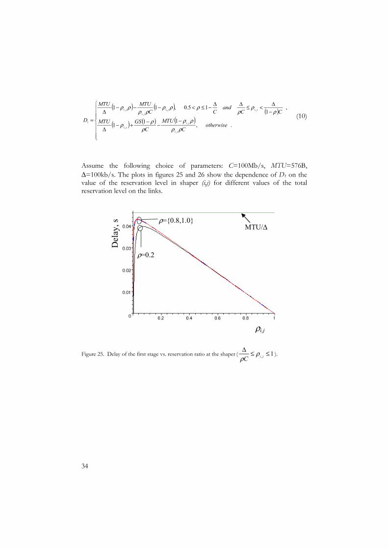
Assume the following choice of parameters: C=100Mb/s, MTU=576B, ∆=100kb/s. The plots in figures 25 and 26 show the dependence of D1 on the value of the reservation level in shaper (i,j) for different values of the total reservation level on the links.
Del
ay, s
ρi,j
MTU/∆ ρ={0.8,1.0}
ρ=0.2
Figure 25. Delay of the first stage vs. reservation ratio at the shaper ( 1, ≤≤∆jiC
ρρ
).

35
Del
ay, s
ρi,j
MTU/∆
ρ=0.2 ρ=0.8
ρ=1
Figure 26. Delay of the first stage vs. reservation ratio at the shaper (small ρi,j ).
One can observe from the figures that for the values of ρi,j in the range (0.01,
0.03) the maximum delay tends to ∆
MTU which is 0.046. The implications of
this observation are described in the next section.
2.4.3 Delay calculus of the second stage and buffer requirements
Recall our architecture of a router with shapers. In the first stage incoming aggregates pass through the shapers. In the second stage, smooth aggregates from n-1 inputs arrive to the queue of the output scheduler. The service curve of the output scheduler is given as
( ) ( ))1(,min ρρσ −+= GSCtCttout .
(11)
An arrival process of the whole aggregate is bounded by the following arrival curve.
( ) ( )MTUnCtta 12 −+= ρ .
(12)
In (12) ( )MTUn 1− is the number of packets which may arrive simultaneously from n-1 input ports. Now computing the maximum horizontal deviation between a2 and σout we obtain the bound on the delay in the output scheduler.

36
( ) ( )C
GSCMTUnD
ρρ
ρ−−−= 11
2 .
(13)
At the final step we compute the delay bound at any node:
( ) 2max,1 DDD jinode += ρ .
(14)
In (14) ρi,jmax is the value of the reservation ratio in shaper (i,j) that maximizes D1. In Section 2.4.2 we found that the dominating term which contributes to the
maximum delay was ∆
MTU . Therefore the smaller the value of ∆ the minimum
allowed GS rate, the higher the delay bound. As an example let us calculate the delay bound for a network with the following parameters. The maximum number of routers between any two edges of the network is h=10. All routers in the network have 10 ports. The capacity of all links is 100 Mb/s, in the attached links 20 Mb/s is available for the guaranteed service traffic (ρC=20Mb/s), and the MTU is 576 bytes. Assume we designed the network to support individual calls from a computer to a GSM phone; therefore, we set the minimum allowed GS rate ∆ equal to 13 kb/s. The maximum end-to-end queuing delay with 10 routers is 3.4 seconds. This is of course unacceptable for real time voice communication. However if under the same conditions the minimum allowed GS rate is 390 kb/s which corresponds to 30 GSM calls, the end-to-end queuing delay with 10 routers is 106 milliseconds which is more acceptable for this type of service. In fact in order to provide a guaranteed service for low bit rate applications a network operator can establish channels of larger bit rates to gateways for a particular service. In the example of calls to GSM phones, the network provider can reserve a channel to the gateway for 30 users and offer this channel to its customers (the task of channel establishment for a particular type of application is out of scope for this thesis and will be considered in future work). In order to avoid losses of GS packets in the second stage, a buffer of ( )MTUn 1− bytes is needed. In Section 2.4.1 we calculated the buffers in all n-1 shapers of the first stage (9), thus the total size of buffers needed in every output port of a router is ( ) ( ) ( )MTUnBn ji 11 max
, −+− ρ , where ρi,jmax is the value of the reservation ratio in shaper (i,j) that maximizes b′ .

37
Buf
fer s
ize,
B
ρi,j
Buf
fer s
ize,
B
ρi,j
a. ρ=0.2. b. ρ=0.8.
Figure 27. Buffer size in a shaper vs. reservation ratio ρi,j.
Figure 27 shows the dependence of the buffer size at shaper (i,j) on its reservation level ρi,j . The maximum buffer size in any shaper is needed when it is configured for half of the outgoing link capacity, therefore ρi,jmax =0.5. In the example where C=100 Mb/s, every router has 10 ports and the minimum allowed rate ∆ is 390 kb/s the total memory needed for buffers at every output port of every router is 70 kB when the reservation ratio ρ is equal to 0.2; over the full range of reservation
ratios 1≤≤∆ ρC
, the maximum buffer size for the considered settings is 335 kB.
2.5 Experimental study
In this section we present the description of simulations which we conducted to evaluate the delay and fairness properties of our scheduling. We will show that the delay values obtained from simulations are bounded by the theoretically computed values. We have implemented our scheduling algorithm in routers for the network simulator ns-2 [58]. The aim of the experiments was to compare the maximum end-to-end delay and the delay jitter which we achieve with our scheduling architecture to the same conditions when using the expedited forwarding per hop behaviour of the differentiated service architecture. According to the specification of the EF PHB [7] one way to provide necessary QoS for the delay-sensitive applications is to treat EF flows as the highest priority flows. One can use a class-based output scheduling in routers (e.g. per-class weighted fair queuing) or a strict priority FIFO scheduling. A series of simulations were performed in order to
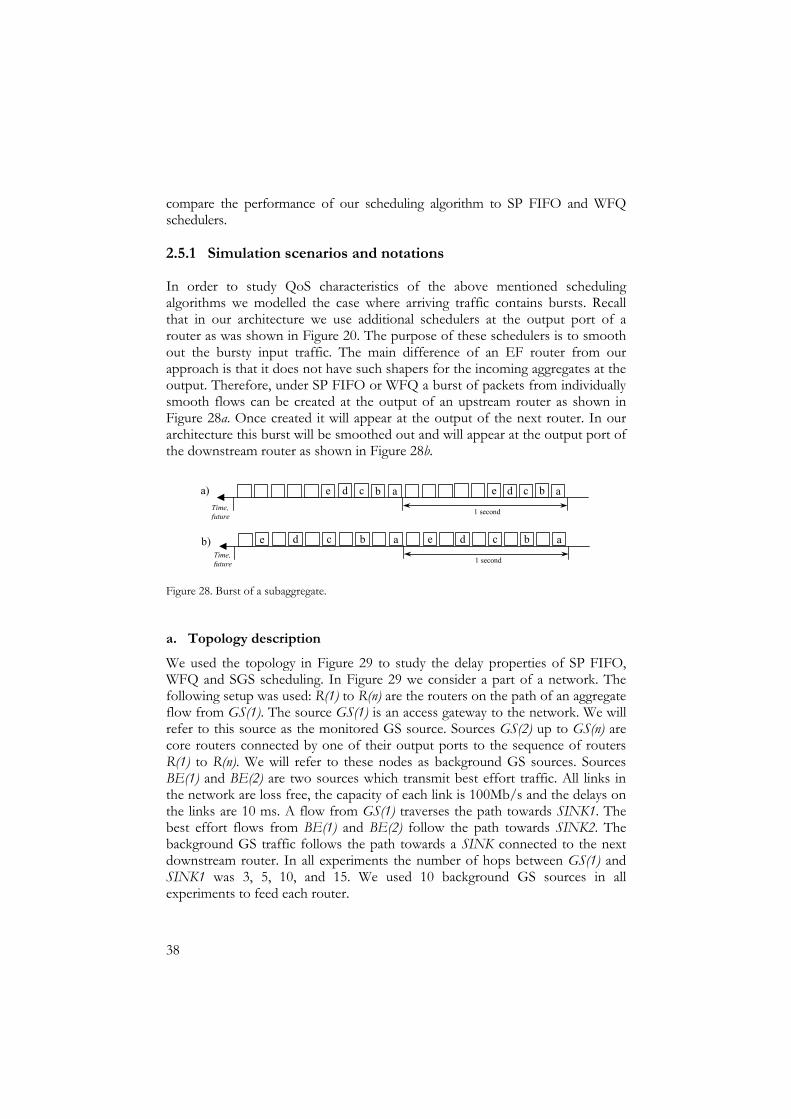
38
compare the performance of our scheduling algorithm to SP FIFO and WFQ schedulers.
2.5.1 Simulation scenarios and notations
In order to study QoS characteristics of the above mentioned scheduling algorithms we modelled the case where arriving traffic contains bursts. Recall that in our architecture we use additional schedulers at the output port of a router as was shown in Figure 20. The purpose of these schedulers is to smooth out the bursty input traffic. The main difference of an EF router from our approach is that it does not have such shapers for the incoming aggregates at the output. Therefore, under SP FIFO or WFQ a burst of packets from individually smooth flows can be created at the output of an upstream router as shown in Figure 28a. Once created it will appear at the output of the next router. In our architecture this burst will be smoothed out and will appear at the output port of the downstream router as shown in Figure 28b.
c b a e d e d c a b
1 second
b a ed c d c b e a
1 second
a)
b)
Time, future
Time, future
Figure 28. Burst of a subaggregate.
a. Topology description We used the topology in Figure 29 to study the delay properties of SP FIFO, WFQ and SGS scheduling. In Figure 29 we consider a part of a network. The following setup was used: R(1) to R(n) are the routers on the path of an aggregate flow from GS(1). The source GS(1) is an access gateway to the network. We will refer to this source as the monitored GS source. Sources GS(2) up to GS(n) are core routers connected by one of their output ports to the sequence of routers R(1) to R(n). We will refer to these nodes as background GS sources. Sources BE(1) and BE(2) are two sources which transmit best effort traffic. All links in the network are loss free, the capacity of each link is 100Mb/s and the delays on the links are 10 ms. A flow from GS(1) traverses the path towards SINK1. The best effort flows from BE(1) and BE(2) follow the path towards SINK2. The background GS traffic follows the path towards a SINK connected to the next downstream router. In all experiments the number of hops between GS(1) and SINK1 was 3, 5, 10, and 15. We used 10 background GS sources in all experiments to feed each router.
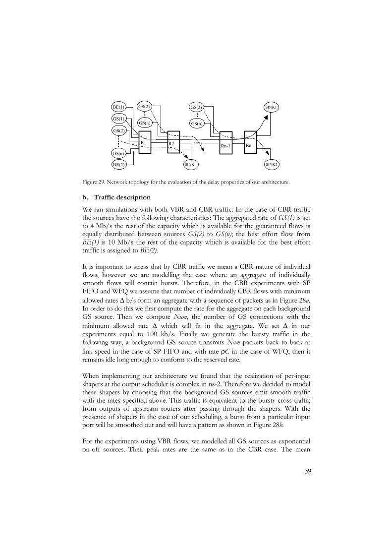
39
BE(1)
GS(1)
GS(2)
GS(n)
BE(2) SINK
GS(n)
GS(2)
GS(n)
GS(2) SINK1
SINK2
R1 R2 Rn-1 Rn
Figure 29. Network topology for the evaluation of the delay properties of our architecture.
b. Traffic description We ran simulations with both VBR and CBR traffic. In the case of CBR traffic the sources have the following characteristics: The aggregated rate of GS(1) is set to 4 Mb/s the rest of the capacity which is available for the guaranteed flows is equally distributed between sources GS(2) to GS(n); the best effort flow from BE(1) is 10 Mb/s the rest of the capacity which is available for the best effort traffic is assigned to BE(2). It is important to stress that by CBR traffic we mean a CBR nature of individual flows, however we are modelling the case where an aggregate of individually smooth flows will contain bursts. Therefore, in the CBR experiments with SP FIFO and WFQ we assume that number of individually CBR flows with minimum allowed rates ∆ b/s form an aggregate with a sequence of packets as in Figure 28a. In order to do this we first compute the rate for the aggregate on each background GS source. Then we compute Num, the number of GS connections with the minimum allowed rate ∆ which will fit in the aggregate. We set ∆ in our experiments equal to 100 kb/s. Finally we generate the bursty traffic in the following way, a background GS source transmits Num packets back to back at link speed in the case of SP FIFO and with rate ρC in the case of WFQ, then it remains idle long enough to conform to the reserved rate. When implementing our architecture we found that the realization of per-input shapers at the output scheduler is complex in ns-2. Therefore we decided to model these shapers by choosing that the background GS sources emit smooth traffic with the rates specified above. This traffic is equivalent to the bursty cross-traffic from outputs of upstream routers after passing through the shapers. With the presence of shapers in the case of our scheduling, a burst from a particular input port will be smoothed out and will have a pattern as shown in Figure 28b. For the experiments using VBR flows, we modelled all GS sources as exponential on-off sources. Their peak rates are the same as in the CBR case. The mean

40
duration of ON/OFF periods is the default value for ns-2 and is equal to 500 milliseconds. We generate bursty arrivals in the case of SP FIFO in the following way, every background GS source generates an ON period, then it calculates Num, the number of packets that would be transmitted with the reserved rate. Then we assume this number of packets belong to different connections with the minimum allowed rates. After that the background GS source emits Num packets back to back at the link speed, we calculate the remainder of the ON period and add this time to the generated duration of the OFF period. By doing this we model the case where a number of individual VBR connections with minimum allowed rates form an aggregate which contains bursts. For the experiments with WFQ the procedure for traffic generation is the same as for SP FIFO experiments with the exception that during the ON period, the background GS sources emit Num packets back to back with the rate of the aggregate namely, ρC. The goal of all the experiments described above was to measure the end-to-end delay of one GS flow from the monitored GS source. The results of this comparison are presented in the next section.
2.5.2 Comparison of our scheduler to SP FIFO and WFQ schedulers
Experiments were done with the CBR traffic. The monitored flow of 4Mb/s from GS(1) was subjected to the background traffic described in the previous section in every router along the path. We conducted two experiments for the three types of schedulers, firstly with a reservation of 80 percent on all links secondly with 20 percent. The goal was to measure the end-to-end delay of the monitored flow and to see whether SGS scheduling introduces smaller queuing delay than SP FIFO and WFQ. Then we repeated the simulations for the VBR traffic. The duration of each simulation was 20 seconds. We measured the average delay from 15 independent runs of each experiment. In each invocation the random generator was randomly seeded based on the current system time. This is recommended when using ns-2 to obtain non-deterministic results for the same simulation setup. In the experiments 95% of the measured delay values fell within ±50 microseconds from the mean value. In order to capture the steady state behavior we began the measurements five seconds after the simulation was initiated. We have studied the maximum queuing delay in routers under the worst-case arrival of the GS traffic in the CBR experiments. As was expected the resulting

41
maximum queuing delay of the monitored flow is smaller in the case of our scheduling architecture than in the case when SP FIFO and WFQ were used. In comparison to SP FIFO the delay in the case of SGS is smaller for 190 milliseconds with a reservation ratio ρ=0.2 and twice as small for ρ=0.8. In comparison to WFQ the delay in the case of SGS scheduling is 28 times smaller for ρ=0.2 and 14 times smaller for ρ=0.8. The results of these experiments are shown in Figures 30 and 31.
Max
imum
del
ay, m
illis
econ
ds
Number of hops
WFQ
SGS
Max
imum
del
ay, m
illis
econ
ds
Number of hops
WFQ
SGS
a. ρ=0.2. b. ρ=0.8.
Figure 30. Maximum queuing delay of the monitored GS flow for the CBR case with WFQ and SGS.
Max
imum
del
ay, m
illis
econ
ds
Number of hops
SP FIFO
SGS
Max
imum
del
ay, m
illis
econ
ds
Number of hops
SP FIFO
SGS
a. ρ=0.2. b. ρ=0.8.
Figure 31. Maximum queuing delay of the monitored GS flow for the CBR case with SP FIFO and SGS.
We can observe from the figures that the maximum queuing delay in the case of WFQ scheduling is very large in comparison to both SP FIFO and our scheduling.

42
In the case of simultaneous arrivals of packets with the rate of the aggregate, WFQ offers a much lower service rate. This experiment shows that presence of per-input shapers drastically decrease the queuing delay in the case of bursty traffic. Let us apply now the delay bound calculated in Section 2.4 to our experimental topology (see Figure 29) and compare the results with the delay values obtained from simulations. In our experiments the monitored flow enters every router through a designated input port and is multiplexed at the output with flows arriving from other inputs. In order to compute the bound for this particular case consider an input shaper where the monitored flow arrives. Thus, setting ∆=4 Mb/s and MTU=576 B as in our simulations we obtain the delay bound as shown in Figure 32. As we can see for both values of utilization factor ρ the theoretical curve indeed bounds the experimental one. The maximum queuing delay for the monitored flow after 15 routers is 23 milliseconds in simulations with ρ=0.2 and the theoretically computed bound for the same conditions is 33 milliseconds. As for the case where ρ=0.8 the maximum delay attained in the simulations is 5 milliseconds and the theoretically computed bound is 8 milliseconds. The difference in the delay values between those obtained experimentally and those obtained theoretically is in order of tens of milliseconds. This is because in our experiments we could not model the worst possible case where the arrival time of packets from different inputs is synchronized in all routers.
Del
ay, s
Hops, h
Theoretical
Simulations
Del
ay, s
Hops, h
Theoretical
Simulations
a. ρ=0.8 b. ρ=0.2
Figure 32. Theoretical vs. experimental delay bound.
By looking at the maximum and minimum delays for SGS scheduling we have seen that they grow almost linearly with the number of hops, Figure 33 illustrates this. The fact that the delay grows linearly with number of hops was shown in Section 2.4 the simulation results also confirm this. The linear growth of the minimum and maximum delays also explains the small variations in the delay jitter. The maximum delay jitter is the difference between the minimum and maximum end-

43
to-end delays. In the case of VBR traffic where ρ=0.8 the maximum jitter is 1.83 milliseconds after 15 hops, in the case where ρ=0.2 this value is 5.49 milliseconds. Reservation values of less than 0.5 (in our case 0.2), lead to packets being delayed for one or more idle periods, this accounts for on higher jitter value.
Del
ay, m
illis
econ
ds
Number of hops
Max delay CBR Max delay VBR Min Delay CBR, VBR
Del
ay, m
illis
econ
ds
Number of hops
Max delay CBR Max delay VBRMin Delay CBR, VBR
a. ρ=0.8 b. ρ=0.2
Figure 33. Min and max delays attained with SGS for GS flow VBR and CBR traffic.
We continued our experiments by looking at the delay jitter of the monitored flow for the VBR case. Simulations show that for both values of the reservation level our scheme introduces much smaller jitter than SP FIFO and WFQ scheduling, figures 34 and 35 illustrate this. Using the strict priority scheduling the monitored flow is affected by bursty traffic from other input ports. It is possible that a burst of packets can be created due to the effect of flow multiplexing. This phenomenon may increase with the number of hops. In our scheme the multiplexed flows from the input ports in a router are reshaped and smooth. When making a comparison of SGS with WFQ scheduling we may observe the effect of having per-input shapers at the output ports. Although functionally WFQ is similar to our algorithm, in the sense that the outgoing traffic rate is not larger then the sum of individual rates it has to deal with bursty traffic from the inputs. The traffic destined to a particular output port arrives with the rate of the aggregate from all inputs while the output WFQ scheduler works at the rate much lower than the sum rates of these aggregates. This causes very large queuing delay, which results in high delay jitter values when WFQ scheduling is used, figures 35a and 35b show this.

44
Del
ay ji
tter,
mill
isec
onds
Number of hops
Priority
SGS
Del
ay ji
tter,
mill
isec
onds
Number of hops
Priority
SGS
a. ρ=0.2. b. ρ=0.8.
Figure 34. End-to-end jitter of the monitored GS flow for the VBR case with SP FIFO and our schedulers.
Interesting observations can be made on delay properties of SP FIFO and WFQ. As one can see from Figure 36a the delay jitter of WFQ in the case where ρ=0.8 is larger than in the case of SP FIFO. This difference is even more noticeable in the case of small values of ρ (Figure 36a). The explanation of this behavior is in the nature of SP FIFO scheduling. Even in the case of bursty traffic, it serves GS packets at full link speed with non-preemptive priority. With a similar arrival pattern, WFQ offers a much lower service rate.
Del
ay ji
tter,
mill
isec
onds
Number of hops
WFQ
SGS
Del
ay ji
tter,
mill
isec
onds
Number of hops
WFQ
SGS
a. ρ=0.2. b. ρ=0.8.
Figure 35. End-to-end jitter of the monitored GS flow for the VBR case with WFQ and our scheduler.

45
Del
ay ji
tter,
mill
isec
onds
Number of hops
WFQ
Priority
Del
ay ji
tter,
mill
isec
onds
Number of hops
WFQ
Priority
a. ρ=0.2. b. ρ=0.8.
Figure 36. End-to-end jitter of the monitored GS flow for the VBR case with WFQ and SP FIFO schedulers.
2.5.3 Link utilization properties of our scheduling algorithm
In this experiment we studied the link utilization properties under the three considered schedulers. This time we do not include the hop count factor, therefore we decided to continue simulations using the topology in Figure 37. The sources, routers, links, and traffic specification are the same as in Section 2.5.1a.
BE(1)
GS(1)
GS(2)
GS(n)
BE(2)
SINK1
SINK2
R1 R2
Figure 37. Network topology for evaluation of the fairness and link utilization properties of our architecture.
We set all sources so that they can emit traffic with variable size packets in the interval [40, 1500] bytes, we used an MTU of 1500 bytes. In order to generate packets of variable sizes, we choose numbers from the exponential distribution with a mean of 100 bytes. If the generated values are less than 40 bytes or larger

46
than 1500 bytes the packet length for these cases is rounded to the respective value. We varied the load of the GS traffic from 20% to 80% of the link capacity and measured the utilization of the link between R(1) and R(2). We compare the utilization for the usage of SP FIFO/WFQ and two variants of the implementation of our algorithm. For variant one when the remainder of the GS burst period is not sufficient to transmit next GS packet, the scheduler remains idle until the beginning of the BE burst period. For variant two under the same conditions the scheduler starts to serve best effort packets immediately. The results of this experiment are shown in Figure 38.
Util
izat
ion
ρ
SP FIFO and WFQ
Our scheduler Variant 2
Our scheduler Variant 1
Figure 38. Utilization of the link capacity.
Obviously with variant two we achieve higher utilization. The shape of the utilization curve in the case of our scheme can be explained as follows, when the ratio of the GS traffic tends to 0.5 the lengths of both the GS burst and BE burst periods tends to one MTU. This results in the situation where a smaller number of variable length packets may fit into the service interval, which in turn results in smaller utilization of the link capacity. This effect however does not appear in the case of SP FIFO and WFQ because of the work-conserving nature of these schedulers. These schedulers never remain idle when there is a packet to send.
2.5.4 Fairness of our scheduling with respect to best effort traffic
In this experiment we studied the impact of our scheduling and SP FIFO schemes on a monitored best effort flow. For this purpose we used the topology in Figure 37. The description of the sources, routers, links as well as traffic specification are identical to those in Section 2.5.1a. The monitored BE flow from BE(1) follows the path towards SINK1 and the other flows towards SINK2. The number of GS sources is varied from 10 to 100. The results of the experiments with ρ=0.8 and ρ=0.2 are shown in Figure 39. The following observation was drawn from the simulations: For both values of the reservation

47
level our scheme performs better with regard to best effort flows. This is due to the difference between the two scheduling schemes: Under strict priority scheduling GS traffic gets full priority over best effort traffic therefore the BE packets can only be transmitted when there are no packets in the GS queue. In our scheme the best effort traffic gets certain guarantees to transmit even in case of simultaneous arrivals of GS packets.
SP FIFO ρ=0.8
SP FIFO ρ=0.2
SGS ρ=0.8 and ρ=0.2
Figure 39. Delay jitter of the monitored best effort flow.
2.6 Summary of our scheduling architecture
The packet scheduling architecture presented in this chapter is developed to provide strict delay guarantees and zero packet loss for guaranteed service flows. The analysis of the related work showed that having pure output scheduling a finite delay bound cannot be achieved without limiting the reservation ratio for GS flows and restricting the network topology. We therefore have developed a scheduling scheme where incoming aggregates, which might contain bursts due to flow multiplexing, are reshaped before entering the buffer of the output scheduler. We have shown experimentally that the presence of such shapers drastically decrease the maximum queuing delay in routers. We performed an analysis of our proposed architecture using network calculus and calculated the worst-case end-to-end queuing delay. As was shown the proposed scheduling provides finite delay bound for guaranteed service flows. The SGS scheduling algorithm provides also fair service to the lower priority traffic for all values of reservation level ρ. The calculated size of buffers in the output port ensures lossless handling of guaranteed service packets in the core routers.


49
CHAPTER 3. SENDER ORIENTED SIGNALING FOR A
SIMPLIFIED GUARANTEED SERVICE
A resource reservation scheme is important for providing guaranteed service to real-time applications. Today the only protocol that is standardized for the Internet is the resource reservation protocol RSVP. Development of the next generation of signaling protocols is still an open research issue. We have therefore developed a simple signaling protocol by means of which applications that use the guaranteed service may explicitly reserve capacity in all nodes along a path. We have named our protocol SOS, which is an acronym for ‘sender oriented signaling’. Our signaling protocol has the following properties: It does not require per-connection soft-states in the core routers, the processing time of a signaling message is small, and the protocol tolerates loss of all types of messages. In the following sections we present a complete description of the protocol’s operation in the end systems and routers. We begin with a brief introduction of signaling protocols and their classification in Section 3.1. We describe the related work in the area of signaling protocols in Section 3.2. In Section 3.3 we focus on the operation of our signaling protocol in the end systems and routers. We elaborate on the encoding scheme for signaling messages in the current format of the IP packet header in Section 3.4. The fault handling operation of our protocol during signaling message loss and when rerouting occurs is described in Section 3.5. Section 3.6 focuses on experimental studies of the protocol’s performance. We summarize the discussion of the signaling protocol in Section 3.7.
3.1 Signaling protocols in brief
In the simplest case the operation of a resource reservation protocol can be described as follows. In order to establish a connection with certain QoS characteristics, an end system issues a reservation message. The initiator specifies the traffic and quality parameters for the connection in this message. The success of the reservation is indicated by reception at the source of the confirmation
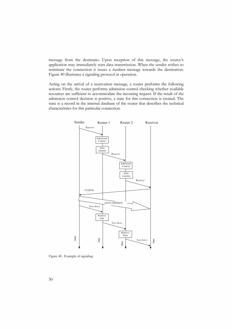
50
message from the destinatio. Upon reception of this message, the source’s application may immediately start data transmission. When the sender wishes to terminate the connection it issues a teardown message towards the destination. Figure 40 illustrates a signaling protocol in operation. Acting on the arrival of a reservation message, a router performs the following actions: Firstly, the router performs admission control checking whether available resources are sufficient to accommodate the incoming request. If the result of the admission control decision is positive, a state for this connection is created. The state is a record in the internal database of the router that describes the technical characteristics for this particular connection.
Sender ReceiverReserve
time
Admission Control
State creation
Admission Control
State creation
Router 1 Router 2
Remove state
Remove State
DATA SESSION
Reserve
Reserve
Confirm
Tear down
time tim
e
time
Tear down
Tear down
Figure 40. Example of signaling.
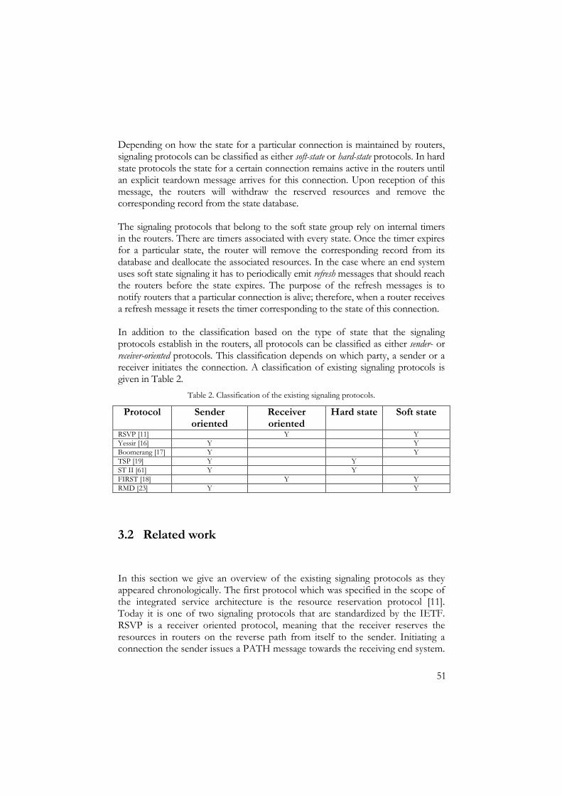
51
Depending on how the state for a particular connection is maintained by routers, signaling protocols can be classified as either soft-state or hard-state protocols. In hard state protocols the state for a certain connection remains active in the routers until an explicit teardown message arrives for this connection. Upon reception of this message, the routers will withdraw the reserved resources and remove the corresponding record from the state database. The signaling protocols that belong to the soft state group rely on internal timers in the routers. There are timers associated with every state. Once the timer expires for a particular state, the router will remove the corresponding record from its database and deallocate the associated resources. In the case where an end system uses soft state signaling it has to periodically emit refresh messages that should reach the routers before the state expires. The purpose of the refresh messages is to notify routers that a particular connection is alive; therefore, when a router receives a refresh message it resets the timer corresponding to the state of this connection. In addition to the classification based on the type of state that the signaling protocols establish in the routers, all protocols can be classified as either sender- or receiver-oriented protocols. This classification depends on which party, a sender or a receiver initiates the connection. A classification of existing signaling protocols is given in Table 2.
Table 2. Classification of the existing signaling protocols.
Protocol Sender oriented
Receiver oriented
Hard state Soft state
RSVP [11] Y Y Yessir [16] Y Y Boomerang [17] Y Y TSP [19] Y Y ST II [61] Y Y FIRST [18] Y Y RMD [23] Y Y
3.2 Related work
In this section we give an overview of the existing signaling protocols as they appeared chronologically. The first protocol which was specified in the scope of the integrated service architecture is the resource reservation protocol [11]. Today it is one of two signaling protocols that are standardized by the IETF. RSVP is a receiver oriented protocol, meaning that the receiver reserves the resources in routers on the reverse path from itself to the sender. Initiating a connection the sender issues a PATH message towards the receiving end system.

52
Acting on the arrival of this message every router creates a state for this connection. Upon reception of the PATH message the receiver issues a RESV message which follows the same route in the reverse direction towards the initiator and reserves the resources according to the receiver’s QoS capabilities. In RSVP the receiver periodically emits refresh messages, which makes RSVP a soft-state protocol. The major concern of the research community about RSVP is its scalability in large IP networks. The theory that RSVP does not scale well since it installs per-connection states led to the appearance of some new signaling protocols [16-19]. However, none of them has yet found practical application in the Internet. The common opinion of the research community is that there is a need for a next generation signaling protocol, which can overcome the inflexibility of RSVP. The recently created IETF working group Next Steps in Signaling (NSIS) [15] develops the specification of the next generation signaling. At the moment the working group defines only the framework of the new signaling protocol, the protocol’s operation is not yet specified. It is worth mentioning the work in [12, 20]. The authors point out the ability of RSVP to scale in a large network by performing flow aggregation on the boundaries of administrative domains and optimisation of its implementation in all network devices. The work in [21, 22] suggests several extensions to RSVP which improve its performance. The Ticket Signaling Protocol (TSP) [19] is a lightweight resource reservation protocol for unicast IP traffic. It is the first protocol which addresses the issues of the complexity of RSVP. The resources can be reserved on a per-connection basis without introducing per-flow state in the network. The main idea of this protocol is the usage of a so-called ticket. When the reservation request propagates through the network it can either be accepted or rejected in each router. When the reservation reaches the receiver it issues an acknowledgment that contains the traffic specification for the connection. Upon reception of the acknowledgment, the sender transforms this message into a ticket. This is a refresh message transmitted periodically through the network to confirm the usage of the resources. The protocol has remained at the level of a prototype implementation. YESSIR (YEt another Sender Session Internet Reservations) [16] differs from RSVP in the following ways, it is an in-band protocol, meaning that it uses signaling messages of the already existing protocol RTP. This implies easier implementation of the protocol in the end systems. Secondly it is sender oriented, meaning that the resource reservation request is initiated by the sender. The developers argue that the sender-oriented nature of the protocol significantly reduces its implementation complexity. Like RSVP, YESSIR relies on per-connection soft states in all the routers. YESSIR is not standardized for the Internet.

53
ST-II is a set of protocols for real-time communication [60, 61]. The setup protocol of ST-II is another sender-oriented scheme for bandwidth reservation. The protocol was designed for point-to-multipoint scenarios. The main concept of the protocol is to install multicast forwarding state and reserve resources along each subnet of the multicast tree. The protocol uses six types of messages: The CONNECT message issued by a sender is used to establish a connection, the ACCEPT message issued by a receiver to signal success of the reservation, the DISCONNECT and REFUSE messages to explicitly teardown a connection. Two other message types are used to change the parameters of a connection and to establish the reservation for new multicast members. The robustness of the protocol is assured by reliable message retransmission and a special protocol for ST-routers to recover from path changes. The protocol is standardized by the IETF and the work on the extension of its operations is ongoing. Boomerang [17] is another attempt to address the issues of the complexity of RSVP. It uses one message to set up bi-directional soft-state reservation in the routers. The authors modify the ICMP protocol so that the reservation is included in an ICMP request message. Usage of the ICMP protocol for Boomerang requests allows simple implementation in the end systems and routers. The setup of a connection is done in Boomerang by exchange of two messages. The main difference of this signaling protocol from RSVP is the usage of the same protocol message for the reservation and maintenance of the connection. The protocol establishes soft state in all the routers. The Flow Initiation and Reservation Protocol (FIRST) [18] is a reservation protocol for multicast traffic. It establishes hard state in the routers and assumes that routes for flows with guarantees are not changed with time. The principle of this protocol is very similar to RSVP: FIRST is a receiver oriented protocol, the sources establish the states in the routers and the receivers actually reserve the resources on the reverse path. The connection states in FIRST are hard, meaning that there are no refresh messages for the established connection. The state of the particular connection should be explicitly deleted from the routers by a termination message. This protocol remain at the level of a proposal without further analysis. The recently proposed RMD scheme (resource management in diffserv) [23] uses aggregated soft state in the core routers. The ingress routers to a diffserv domain issue reservations for the aggregate flows towards the corresponding egress router. The core routers allocate the needed resources and monitor the ongoing traffic. In the case of congestion the core routers notify the egress nodes about this event by specially marking the users data packets. The way RMD handles fault situations is complex since it involves the detection of the ingress nodes for every congestion-marked packet. The protocol is currently under development.
54
Different approaches for the resource reservation deal with centralized schemes, as described in [28]. In these approaches there exists a central point, a bandwidth broker, which has a map of the entire network and keeps track of the available resources. The resource reservation operation in this case converges to a simple request to the bandwidth broker to allocate the needed resources end-to-end. The centralized approaches are not considered in this thesis. Our signaling protocol described below is similar only to the RMD proposal described above. We use aggregated soft state in the core routers. However the way RMD handles fault situations is more complex than in our protocol. In our protocol we do not overload the egress routers with the detection of the corresponding ingress routers for failed connections. Instead sources terminate the ongoing connections in the case of signaling messages loss. Our protocol differs from the approaches described above in the following ways, it uses a simpler traffic descriptor: We define a connection solely by its peak rate. Secondly, the protocol does not establish per-flow soft states in the routers. Instead we introduce soft state for the aggregate reservation on a network link.
3.3 Basic operations of our signaling protocol
The idea behind our signaling is simple, it uses the additivity of the reservation state (see Definition 6 in Section 1.6). A router has four state variables for each outgoing link. We keep track of the capacity available for the guaranteed service on each network link in a variable CGS, and have three public state variables for the requested, confirmed and refreshed capacity, Rr , Rc and Rref. All users are able to modify these variables by means of the signaling protocol. The following messages are needed for the signaling: • The reservation message mR(r) for the amount of capacity r. • The confirmation message mC(r) from the initiating party for the reserved
capacity. • The refresh message mRef(r) for the amount of capacity r. • The tear down message mT(r), which indicates that the initiating party
terminates the connection and releases the reserved capacity. In our protocol we define the requested rate r in all signaling messages as a multiple of ∆, where ∆ bits per second is a minimum value (quantum) of reservation.

55
It is important to stress that the service specifies that all the signaling messages are carried in the part of the link capacity allocated to the guaranteed service traffic and therefore they are not subject to congestion-induced loss.
3.3.1 Time cycles and synchronization of network devices
For the purposes of long-term garbage collection, which is presented below, we specify that all devices that participate in the communication process, i.e. the end systems, access gateways and core routers operate in cycles of fixed duration Tc. The beginning of each cycle is synchronized in all devices by using SNTP [63]. All events of sending signaling messages from the end systems and receiving them in the routers take place in strictly defined time intervals within a cycle. Figure 41 shows how a cycle is divided into intervals in the end systems and routers. The time intervals Tc, TRref and Tmargin are constants specified for the routers, other time intervals are computed in relation to these. The precise definition of each time interval is given in the corresponding sections (for the end systems in Section 3.3.2 and for the routers in Section 3.5.1 b).
TRref
TSref
One cycle of duration Tc
END SYSTEMS:
ROUTERS: Tmargin
Figure 41. Time intervals in the end systems and routers.
3.3.2 SOS operation in end systems
In order to establish a guaranteed service connection, the initiator sends a reservation message mR(r) towards the destination. After issuing this message a waiting timer is started with a value T. This is the allowed waiting time for an acknowledgment at the sender and it is a constant specified for the service. By defining T as a maximum round trip time we ensure correct handling of delayed acknowledgments: If no acknowledgment arrives during T seconds, the initiator sends a new reservation request. The establishment of a connection is repeated until an acknowledgment arrives or the sender decides to not transmit again. If an acknowledgement was delayed by the receiving end system and the sender times out before receiving this message it will issue a new reservation message. The acknowledgment for the old reservation will be ignored. The core routers

56
will handle this case as a lost reservation and will clean up the reserved capacity during garbage collection (see Section 3.5.1a). Reservations may be sent during the whole duration of the cycle Tc (see Figure 41). Each signaling message has a unique identifier except an acknowledgement that has the same identifier as the corresponding signaling message. An acknowledgment is issued by the receiver when it receives any signaling message except a teardown, and it is encoded as a zero-rate reservation, i.e. mR(0). For the sender an acknowledgment indicates a successful transmission of the message along the path. If the expected acknowledgment did not arrive at the sender, this situation is interpreted as an error and will be handled as shown in Table 3.
Table 3. Handling of errors at the sender.
Event Action
Acknowledgment for mR() did not arrive during time period T. Retransmit reservation after T. Acknowledgment for mC() did not arrive during time period T. Interrupt ongoing session without
issuing a tear down. Acknowledgment for mRef() did not arrive during time period T. Interrupt ongoing session without
issuing a tear down. When an acknowledgment for a reservation is received, the sender confirms it by transmitting a confirmation message towards the destination and may immediately start to send data at a rate below r b/s. During the lifetime of the established connection the sender transmits refresh messages mRef(r). The refresh message is sent at a random point within TSref of each cycle. TSref is the time during which the sender may transmit refresh messages. It is computed as TSref=TRref -T /2. Since we defined T as a maximum round trip time the duration of TSref ensures that the refresh messages will arrive to any router before TRref. If the sender does not receive an acknowledgment for the issued mRef() then, according to Table 3, the sender must interrupt the connection without issuing a teardown message and setup a new reservation. When the initiating party wishes to end the session, it sends a teardown message releasing the reserved capacity along the path. The diagram in Figure 42 represents the behaviour of the sender and the receiver in the case where no message is lost in the network.

57
Sender Receiver
Duration of session
mT(r)
mC(r)
mR(0)mR(r)
Data rate
below r
time time
mR(0)
mRef(r)
mR(0)
Figure 42. Lossless operation of the sender and the receiver.
3.3.3 SOS operation in routers
When a router receives mR(r), it performs admission control based on the requested rate. The router will simply drop a reservation message if it exceeds the remaining capacity available to guaranteed service traffic (r>CGS -Rr). Otherwise it increases Rr and Rref by the bit rate requested in the reservation message. Upon reception of a confirmation message, the router increases the value of Rc by the rate r. In reaction to the arrival of a refresh message, the router increments the Rref variable by the bit rate specified in the refresh message. When the router receives a teardown message, it decreases both Rr and Rc by the rate in the message. If a router gets an acknowledgment message in the form of mR(0), it will not change the state variables. Figure 43 shows the capacity allocation for the signaling messages and the dynamic behavior of Rr , Rref and Rc. The message mR(r) is carried in the available capacity from which it reserves a share, mC(r), mRef(r), and mT(r) use the established reservation. Thus, the messages are not subjected to congestion, however they may be lost due to a link failure or bit errors. Acknowledgments are carried in the unallocated part of the GS capacity and might therefore be lost due to buffer overflow. The router will handle this situation by garbage collection described in Section 3.5.1b. The algorithm of SOS operation in the routers is presented as pseudo-code in Appendix 2.

58
time
mR(r) mC(r) mT(r)
CGSRr Rc
Rc Rr Rr
RcRr
Rc
mRef(r)
Rref Rref Rref
Figure 43. Dynamic behavior of Rr, Rref and Rc.
3.4 The message encoding scheme
We decided to encode all four types of the signaling messages in the IP header, so that the length of any signaling message can be as small as the length of the IP header (20 bytes). In order to do this we use the ToS field to encode the messages of the signaling protocol and the data of the controlled load, best effort and guaranteed service classes. In addition we re-define the Fragment Offset fields of the IP header in order to encode the rate value in the signaling messages. We will refer to the numerical values of the ToS field in the diffserv like manner as code points. According to [64] six bits (0 – 5) of the IPv4 ToS field are assigned as diffserv code points. The document defines three pools of code points: Values from pools one and three (48 CPs) are used to encode the existing diffserv classes [5]. The second pool of code points is reserved for experimental or local use. At the current moment we have decided to assign code points for our architecture from pool two. The second pool is defined as xxxx11, where xxxx are the highest significant bit positions available for free assignment. The newly defined CP values are given in Table 4. The signaling messages can be distinguished by a combination of the CP value and the rate value. Recall that the operations of processing the reservation and teardown messages are symmetric; we can therefore encode a teardown message as a reservation with a negative requested rate. Recall also that an acknowledgement message in our protocol is a reservation message with the requested rate equal to zero. To summarize we need a signed integer in order to represent the rate in the signaling messages.

59
Table 4. New code points for our architecture.
Code Point Binary Hex
Type of message
000011 0x3 GS data 000111 0x7 mR(), mT(), and ACK 001011 0xB mC() 001111 0xF mRef() 010011 0x13 CLS probe 010111 0x17 CLS data 011011 0x1B BE data
Since the length of any signaling message will be 20 bytes, the IP packet that carries a signaling message will never be fragmented in the network. We therefore decided to use the 13 bits Fragment Offset field to encode r, the rate value of the signaling message as shown in Figure 44. As was shown above we need a signed integer to represent the value r; therefore, we decided to assign the most significant bit of the Fragment Offset field to the sign of the rate value. Thus r is a 12 bit signed integer. Recall that users of SOS may specify their requested rate as multiples of ∆, where ∆ b/s is the minimum allowed reservation rate. We decided therefore that the signaling messages will carry only the multiple of ∆. In this way one reservation message may indicate a request for up to 4095∆ b/s.
13 bit Fragment Offset field
Sign Rate Value
1 bit 12 bits
Figure 44. New definition of the “Fragment Offset” field.
To summarize mR(r) is encoded as CP=0x7 and as a positive rate value, mT(r) as CP=0x7 and a negative rate value, ACK as CP=0x7 and zero-rate value. We decided to allocate separate code points for confirmations and refreshes, thus mC(r) is encoded as CP=0xB and a positive rate value and finally mRef(r) as CP=0x13 and a positive rate value. The extended pseudo-code of the packet classifier at the output port of a router and SOS processing block is presented in Appendix 3. The classification of a data packet of any type of service (GS, CLS, BE) as well as any signaling message takes one comparison operation. The signaling message which requires more operations during the processing is the reservation message. To process this message it takes three operations of comparison. This simplicity of operation allows SOS to

60
process up to 700,000 signaling messages per second (see Section 3.6.6 for more details).
3.5 Fault handling in routers
A loss of signaling messages can occur in routers due to one of the following four scenarios: Lack of resources, a link failure, bit errors during transmission of signaling messages and rerouting of certain flows on a new path. In Section 3.3.2 we have described the fault handling mechanisms in end systems. In the case where signaling messages are lost in the network the sources will terminate the connection according to Table 3. However the sources will not issue teardown messages for the terminated connections. This may eventually lead to a situation where all available capacity for GS in the routers is reserved by connections which do not exist. In order to re-establish the reservation levels in routers we have developed two mechanisms for garbage collection, they are described in Section 3.5.1. In the case of rerouting one can consider the following train of thought, current routing protocols are unaware of the differentiation of services in the Internet. Therefore in the case of our service architecture GS packets will be rerouted as all other packets without any reservation. As a result rerouted GS connections from the old path can disturb the ongoing GS sessions on the new unreserved path. In this case the total rate of the incoming aggregates on the new path will be higher than the reserved value. Our solution to this problem is presented in Section 3.5.2 where we describe the rerouting procedure for GS packets.
3.5.1 The garbage collection procedures
There are several cases where routers need garbage collection to re-establish the reservation levels that may be inconsistent due to loss of signaling messages. A reservation message is discarded when a router blocks a reservation request. This means that there will be pending reservations upstream along the path of the message. In case the loss is of a confirmation message, a sender cannot issue a teardown for this connection, since it is impossible to deallocate the capacity on the unconfirmed part of the path. If a teardown message is lost, all the nodes after the point of failure will never receive the message and therefore the amount of capacity which was supposed to be deallocated will remain in use. These situations can potentially lead to a state in which all the capacity in a router is unavailable for new reservations. Some important observations can be made on the frequency of messages loss due to admission control (mR()) and link failures or bit errors (mC(), mT()) and the relationship between them:
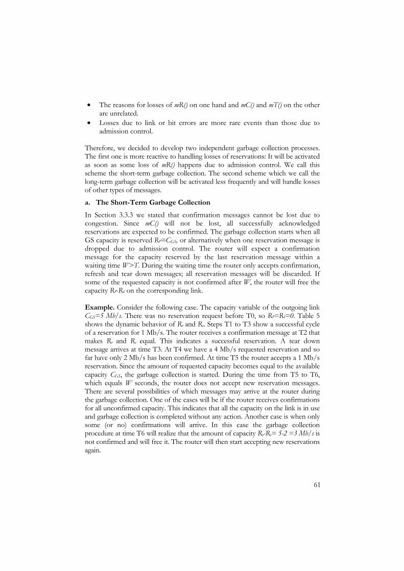
61
• The reasons for losses of mR() on one hand and mC() and mT() on the other are unrelated.
• Losses due to link or bit errors are more rare events than those due to admission control.
Therefore, we decided to develop two independent garbage collection processes. The first one is more reactive to handling losses of reservations: It will be activated as soon as some loss of mR() happens due to admission control. We call this scheme the short-term garbage collection. The second scheme which we call the long-term garbage collection will be activated less frequently and will handle losses of other types of messages.
a. The Short-Term Garbage Collection In Section 3.3.3 we stated that confirmation messages cannot be lost due to congestion. Since mC() will not be lost, all successfully acknowledged reservations are expected to be confirmed. The garbage collection starts when all GS capacity is reserved Rr=CGS, or alternatively when one reservation message is dropped due to admission control. The router will expect a confirmation message for the capacity reserved by the last reservation message within a waiting time W>T. During the waiting time the router only accepts confirmation, refresh and tear down messages; all reservation messages will be discarded. If some of the requested capacity is not confirmed after W, the router will free the capacity Rr-Rc on the corresponding link. Example. Consider the following case. The capacity variable of the outgoing link CGS=5 Mb/s. There was no reservation request before T0, so Rr=Rc=0. Table 5 shows the dynamic behavior of Rr and Rc. Steps T1 to T3 show a successful cycle of a reservation for 1 Mb/s. The router receives a confirmation message at T2 that makes Rr and Rc equal. This indicates a successful reservation. A tear down message arrives at time T3. At T4 we have a 4 Mb/s requested reservation and so far have only 2 Mb/s has been confirmed. At time T5 the router accepts a 1 Mb/s reservation. Since the amount of requested capacity becomes equal to the available capacity CGS, the garbage collection is started. During the time from T5 to T6, which equals W seconds, the router does not accept new reservation messages. There are several possibilities of which messages may arrive at the router during the garbage collection. One of the cases will be if the router receives confirmations for all unconfirmed capacity. This indicates that all the capacity on the link is in use and garbage collection is completed without any action. Another case is when only some (or no) confirmations will arrive. In this case the garbage collection procedure at time T6 will realize that the amount of capacity Rr-Rc= 5-2 =3 Mb/s is not confirmed and will free it. The router will then start accepting new reservations again.
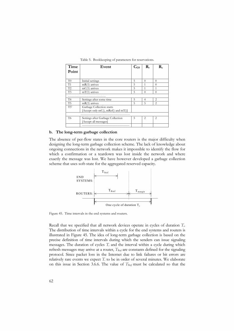
62
Table 5. Bookkeeping of parameters for reservations.
Time Point
Event CGS Rr Rc
T0 Initial settings 5 0 0 T1 mR(1) arrives 5 1 0 T2 mC(1) arrives 5 1 1 T3 mT(1) arrives 5 0 0 ……………………………… T4 Settings after some time 5 4 2 T5 mR(1) arrives 5 5 2 T5’ Garbage Collection starts
[Accept only mC(), mRef() and mT()]
-------------------------------------------------- T6 Settings after Garbage Collection
[Accept all messages] 5 2 2
------------------------------------------------
b. The long-term garbage collection The absence of per-flow states in the core routers is the major difficulty when designing the long-term garbage collection scheme. The lack of knowledge about ongoing connections in the network makes it impossible to identify the flow for which a confirmation or a teardown was lost inside the network and where exactly the message was lost. We have however developed a garbage collection scheme that uses soft-state for the aggregated reserved capacity.
TRref
TSref
One cycle of duration Tc
END SYSTEMS:
ROUTERS: Tmargin
Figure 45. Time intervals in the end systems and routers.
Recall that we specified that all network devices operate in cycles of duration Tc. The distribution of time intervals within a cycle for the end systems and routers is illustrated in Figure 45. The idea of long-term garbage collection is based on the precise definition of time intervals during which the senders can issue signaling messages. The duration of cycles Tc and the interval within a cycle during which refresh messages may arrive at a router, TRref are constants defined for the signaling protocol. Since packet loss in the Internet due to link failures or bit errors are relatively rare events we expect Tc to be in order of several minutes. We elaborate on this issue in Section 3.6.6. The value of TRref must be calculated so that the
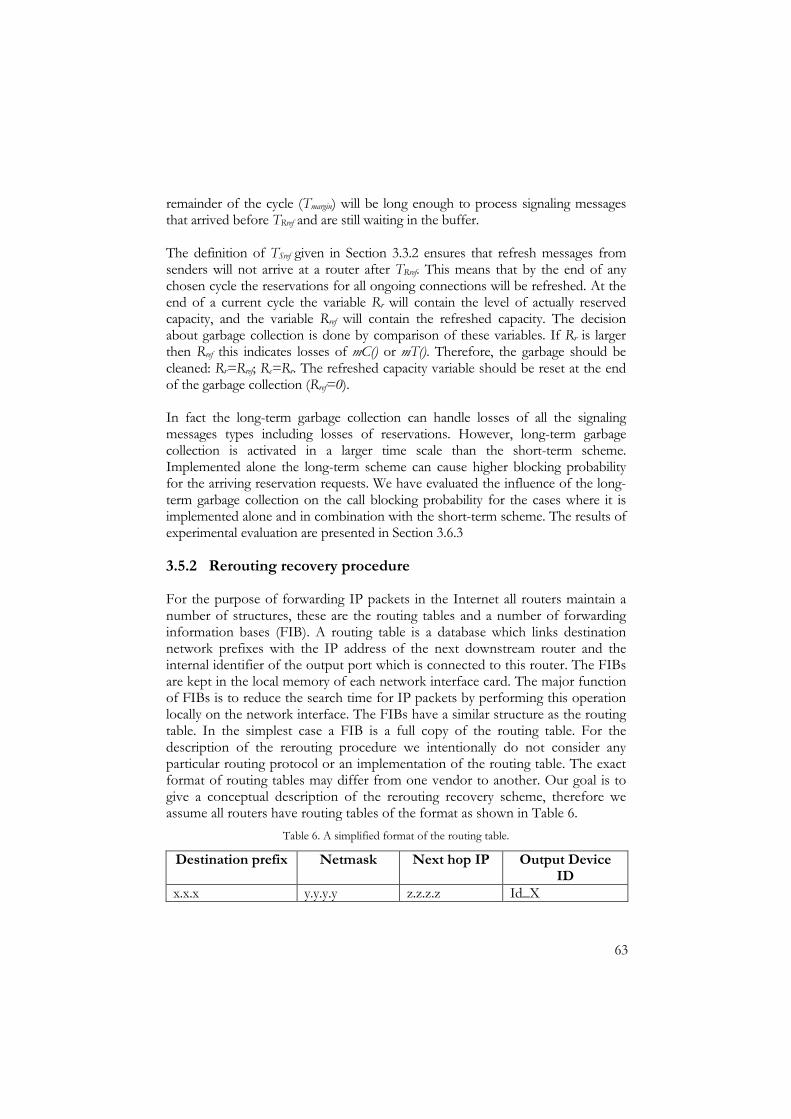
63
remainder of the cycle (Tmargin) will be long enough to process signaling messages that arrived before TRref and are still waiting in the buffer. The definition of TSref given in Section 3.3.2 ensures that refresh messages from senders will not arrive at a router after TRref. This means that by the end of any chosen cycle the reservations for all ongoing connections will be refreshed. At the end of a current cycle the variable Rr will contain the level of actually reserved capacity, and the variable Rref will contain the refreshed capacity. The decision about garbage collection is done by comparison of these variables. If Rr is larger then Rref this indicates losses of mC() or mT(). Therefore, the garbage should be cleaned: Rr=Rref; Rc=Rr. The refreshed capacity variable should be reset at the end of the garbage collection (Rref=0). In fact the long-term garbage collection can handle losses of all the signaling messages types including losses of reservations. However, long-term garbage collection is activated in a larger time scale than the short-term scheme. Implemented alone the long-term scheme can cause higher blocking probability for the arriving reservation requests. We have evaluated the influence of the long-term garbage collection on the call blocking probability for the cases where it is implemented alone and in combination with the short-term scheme. The results of experimental evaluation are presented in Section 3.6.3
3.5.2 Rerouting recovery procedure
For the purpose of forwarding IP packets in the Internet all routers maintain a number of structures, these are the routing tables and a number of forwarding information bases (FIB). A routing table is a database which links destination network prefixes with the IP address of the next downstream router and the internal identifier of the output port which is connected to this router. The FIBs are kept in the local memory of each network interface card. The major function of FIBs is to reduce the search time for IP packets by performing this operation locally on the network interface. The FIBs have a similar structure as the routing table. In the simplest case a FIB is a full copy of the routing table. For the description of the rerouting procedure we intentionally do not consider any particular routing protocol or an implementation of the routing table. The exact format of routing tables may differ from one vendor to another. Our goal is to give a conceptual description of the rerouting recovery scheme, therefore we assume all routers have routing tables of the format as shown in Table 6.
Table 6. A simplified format of the routing table.
Destination prefix Netmask Next hop IP Output Device ID
x.x.x y.y.y.y z.z.z.z Id_X
64
When packets arrive at a router they pass through a route lookup procedure in order to determine where they should be forwarded. The route lookup function extracts the destination IP address from the header of a particular IP packet and performs a search in the forwarding information base. The result of this search is the returned value of the internal identifier of the output port in the router to which the packet should be forwarded. The records in the routing table are inserted based on the information provided by a routing protocol, e.g. OSPF [66]. One of the reasons for inserting a new record in the routing table can be a link failure in the network, in this case new routes are established in the network for affected prefixes. This procedure is called rerouting and avoids the point of failure. When the routing protocol delivers new routing information, the routing table and FIBs must be updated in every router. We can distinguish the following major steps in the procedure for the routing table and FIBs update. • A router receives messages of the routing protocol. • The central processor of the router computes a new routing table (at this
time the router keeps two routing table structures). • When the new routing table is computed it replaces the old one. • New FIBs are downloaded to the interfaces.
As a result of the routing table update the IP packets which were previously forwarded to the output port X might be routed to a new output port Y. In most of the cases the rerouted traffic can overload the new link, which in turn can induce packet loss. It is important to stress that although a routing table may contain an indication about the modification of some routes this information is used for diagnostic purposes and is not used in a route search. Recall that in our service architecture we defined three service classes: The guaranteed service, the controlled load service and the best effort service. The applications which use the last two service classes are less sensitive to packet loss in the network whilst the applications which use guaranteed service have strict requirements on absence packet loss. Thus we need to perform certain actions in order to avoid the loss of GS packets on the new path due to the rerouting of the GS traffic. At the same time routing of the lower priority traffic should not be affected by these actions. There can be different solutions regarding the handling of the rerouted GS connections. Obviously the rerouted GS packets should not be forwarded in the GS part of the capacity on a new unreserved path since this can cause congestion of GS traffic there. Assume that the route lookup procedure accounts for modified routes when resolving the next hop IP address for a particular packet. Therefore when a router recognizes that rerouting occurs for some prefix, it should either stop forwarding the rerouted GS packets or make a reservation for the rerouted GS connections on the new path. The later solution implies additional complex

65
functionality in the core routers. We therefore decided to concentrate on the first variant. In this case the rerouted GS packets can either be dropped or be re-marked as BE packets and forwarded on the new port. The capacity which was previously reserved for this prefix at the old output port will be released by the two garbage collection processes described in Section 3.5.1. In this thesis we focus on the case where rerouted GS packets are re-marked as best effort, since in this case at least some part of GS packets still have a possibility to reach the destination until a new reservation is established for the flow. It is obvious that the re-marking of GS packets should not continue for long periods. After some time the rerouted connections will be terminated by sources and the new GS connections will be established on the new route. Thus we need an indication to stop re-marking of the GS packets. Since the destinations will not send acknowledgments for the re-marked signaling messages, we can rely on the following property of the signaling protocol: If a source does not receive an acknowledgment for either mC() or mRef() it stops the ongoing session at most after T without issuing a tear down message (see Section 3.3.2, Table 3). The router will receive and process the refresh messages of all rerouted GS connections at most after the duration of a cycle Tc. Therefore the re-marking of GS packets should be stopped after ctimeUpdate TT +_ , where TUpdate_time is the time of the last update of the routing table and FIBs and Tc is the duration of a cycle for the long-term garbage collection. For the purposes of the rerouting recovery scheme we need to add a four-bytes field Update_time to the structures of the routing table and FIBs. It is important to stress that although we introduce one additional field, which in consumes 4 bytes of memory per routing table entry, we do not index the routing table by it. Therefore, the time for route lookup is not affected by our modifications. The new structure of the routing table and FIBs is shown in Table 7. The field Update_time contains the system time of the last update of the routing table. When it is larger then zero it indicates that during the last update of the routing table, a new next hop router was assigned for the particular prefix.
Table 7. A modified format of the routing table.
Destination prefix
Netmask Next hop IP
Output Device ID
Update time
x.x.x y.y.y.y z.z.z.z Id_X xx:yy:zz Appropriate changes should be made to the update procedure of the routing table. When a new routing table is computed, the router must compare its contents to the content of the old table. If for any destination prefix the next hop IP address has changed, or a new prefix appeared, the current system time must be filled in the Update_time field for this prefix.
66
We make changes to the forwarding procedure of the network interface cards. Recall that the guaranteed service packets have to be treated differently from packets of the other two classes when rerouting occurs. The packets of the CLS and BE classes however should not be affected by our changes. Therefore we propose two independent packet forwarding procedures: One which will be used for the CLS and BE packets and the other one which will be used for the GS packets. In order to organize invocation of different forwarding functions for packets that belong to different service classes we need to classify them before making the forwarding decision. It was shown in [10] that the classification of packets can be done nearly at a link speed, therefore classification will not significantly increase the forwarding time for packets of all three traffic classes. The flow-chart in Figure 46 describes the modified process of the packet forwarding. We have two functions for route lookup: Route_lookup_GS and Route_lookup_current. The Route_lookup_current can be any efficient route search function, e.g. the LC-tries described in [27]. The difference in the Route_lookup_GS from the Route_lookup_current is the number of returned parameters: In addition to the output device ID and the next hop IP address the forwarding procedure receives also the value of the Update_time for the prefix. This value is used as described below.

67
Receive packet
ToS>=0x3 && ToS<=0xF
Update_time=0
Forward packet
Mark as BE
Rerouting validity test
NO: packet is BE or CLS
YES: packet isGS
Route_lookup_GS Returned parameters: -Next hop IP; -Output device ID -Update_time.
NO: GS packet is not rerouted
YES, GS packet is rerouted mark packet as BE
Classification
Route_lookup_current Returned parameters: -Next hop IP; -Output device ID
Figure 46. Modified forwarding procedure to support the rerouting recovery procedure for GS packets.
One can observe from the above flow-chart that forwarding of packets that belong to the BE and CLS service classes does not contain other operations than the route lookup and actual forwarding. However in the case of forwarding the GS packets we cannot avoid one conditional part: the test on validity of the rerouting. The test on the validity of the rerouting is done by the following check:
( )( )nowTtimeUpdateif C >=+_ , where Tc is the duration of a cycle and now is the current system time. If the condition holds, the rerouting recovery is ongoing. In this case, the rerouted GS packet must be marked as BE packet and forwarded to the output port. If the condition does not hold, it indicates that the rerouting

68
recovery is completed to the GS packets destined for this prefix and they should be forwarded as GS on the new path. In this case the Update_time for the corresponding prefix must be reset to zero. To summarize the rerouting recovery procedure for the GS packets we give a qualitative evaluation of its properties. We can evaluate the procedure by the following criteria: The correctness of the operations and the optimality of the procedure. The correctness of the rerouting recovery procedure is ensured by the fault handling operations in the end systems and routers as described in Section 3.5.1 and the test on validity of the rerouting. The fault handling operations in the end systems ensure that all GS connections will be terminated after the duration of a cycle Tc from the moment when rerouting began. The long term scheme for garbage collection will release the unused bandwidth on the old path at most after Tc from the moment of initiation of the rerouting. The validity test ensures that the Update_time for the rerouted prefix will be reset to zero after Tc from the moment when rerouting began. Regarding the optimality of the proposed procedure consider the following, the packets of the CLS and BE classes are not affected by the rerouting recovery scheme since the procedure does not induce additional operations on the packets’ forwarding path plus the effect of the classification is negligible. As for GS packets, the two tests they must undergo on the forwarding path are not avoidable. This is the cost the GS traffic must pay in networks where rerouting can occur. From the viewpoint of the modifications to the structure of the routing table, they do not increase the route lookup time for a given prefix. Addressing the issues of memory consumption our modifications require additional 4N bytes for the routing table and FIBs, where N is a number of routing entries in the routing table. This can be considered as the major drawback of the proposed solution, however the physical memory is less critical issue than the optimality of the route lookup function which remains unchanged.
3.6 Performance evaluation
In this section we present results from the simulations that we conducted to evaluate the performance of our signaling protocol. Firstly we evaluated the influence of the two schemes for garbage collection (see Section 3.5.1a and 3.5.1b) on call blocking probability. In Section 3.6.3 we show that although the long-term scheme implemented alone introduces much higher blocking probability than the short-term scheme implemented alone, their combination eliminates this effect. The second goal of the experiments is to observe the effect of different values for the duration of the timer T on the average connection

69
establishment time. The results of this experiment are presented in Section 3.6.4. In Section 3.6.5 we evaluate the effect of different durations of the cycle Tc on the call blocking probability and failure rate of ongoing sessions. By failure rate we mean the percentage of the ongoing GS connections that are terminated by sources due to loss of signaling messages. Finally we measure the average processing time of the signalling messages in the routers. The results of this simulation are presented in Section 3.6.6.
3.6.1 The network topology and settings for simulations
We implemented our signaling protocol in the end systems and routers of the network simulator ns-2 [58]. In all our simulations we use a two-stage network as shown in Figure 47.
AG n
GS(1)
GS(2)
GS(n)
AG 1
GS(1)
GS(2)
GS(n)
R
SINK1
SINK2
Figure 47. Network topology for the SOS simulations.
At the first stage, n groups of n sources gain access to n access gateways AG1…AGn. At the second stage, reservation messages from n access gateways arrive at router R. The router has two output links. Sources GS(1) at the first stage try to place a call to the receiver SINK1, and the rest of the sources establish connections with the host SINK2. The calls from every source arrive at the access gateways as Poisson streams with intensity λ calls per second. The duration of each call is exponentially distributed with a mean of µ-1 seconds. If a call is blocked the source will try again after timeout T. In all the experiments described below the following settings were used: The capacity C of all links is 10 Mb/s; 9 Mb/s on all links was allocated for the guaranteed service traffic (CGS=9Mb/s). The number of access gateways and sources connected to each access gateway was equal to 5, the mean duration of a call µ−1 =5 seconds. The minimum allowed GS rate ∆ equals 100 kb/s in all experiments. Since the mean arrival rate λ and the duration of cycle Tc vary in different experiments we will specify these parameters for every experiment in the corresponding sections. The last parameter that we need to specify for the

70
simulations is the duration of the timer T. As was stated in Section 3.3.2 T equals a maximum RTT in our protocol. In the next section we discuss how this parameter can be computed.
3.6.2 Estimation of round trip time
In order to compute the maximum round trip time for our signaling protocol we have to account for the worst-case delay of the signaling messages in the routers. In Section 2.4 we have calculated the maximum queuing delay, which any guaranteed service packet might experience in routers (see equation 14 in Section 2.4.3). Accounting for this result we assume that any signaling message will experience the maximum queuing delay in all routers along its path. Adding the propagation delay on the links the RTT for any GS packet is bounded by
( ) npropagationode DhhDRTT 122 ++= .
(15)
where h is the number of routers along the path of a GS packet. Let us now compute the RTT value for our simulation topology. In our experiments the minimum allowed GS rate is 100 kb/s, the MTU is 576 B, C=10 Mb/s, the propagation time on all links is 10 ms. Applying (14), the maximum queuing delay of a GS packet in one router is 40 ms. Since on a path from source to sink all signaling messages cross two routers with our scheduler, i.e. one access gateway and one router, the maximum queuing delay for the whole path is 80 ms. In our simulations acknowledgements are not delayed in routers on the return path, therefore we do not count the queuing delay of acknowledgements for the calculation of RTT. Adding the propagation delay of 60 ms of from any source GS(i) to its SINK and back the maximum RTT for a GS packet in our simulation topology is 140 ms; therefore, we set T=0.14 in all our experiments. Although a computation of the maximum RTT for our simulation topology is straightforward, the computation of this value in real networks is more problematic. The reason for this is that the end systems do not know in advance the number of routers on the path to a destination. Moreover the propagation delays on all links are not known either. Therefore in the real environment, estimation of the RTT will be used instead. Obviously an accurate estimation of this parameter is essential for our signaling protocol since the incorrect estimation of the round trip time may affect both the protocol’s behavior and the call blocking probability. Naturally underestimation of this parameter will result in ignoring the delayed acknowledgements for all signaling message types, which in turn will lead to the failures of ongoing sessions. On the other hand, overestimation of T will result in a larger connection establishment time. The estimation methods for the RTT are out of scope for this thesis, however we experimentally evaluate the effect of overestimation of the RTT value, both on call
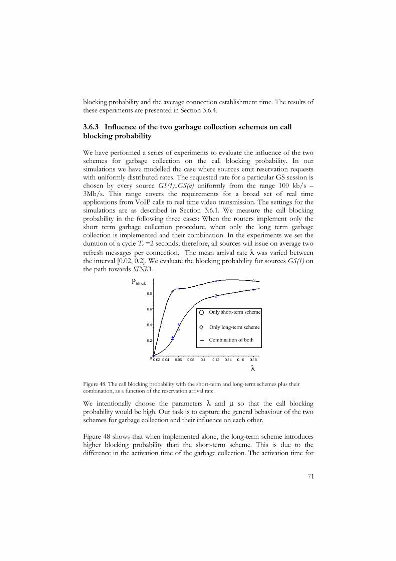
71
blocking probability and the average connection establishment time. The results of these experiments are presented in Section 3.6.4.
3.6.3 Influence of the two garbage collection schemes on call blocking probability
We have performed a series of experiments to evaluate the influence of the two schemes for garbage collection on the call blocking probability. In our simulations we have modelled the case where sources emit reservation requests with uniformly distributed rates. The requested rate for a particular GS session is chosen by every source GS(1)..GS(n) uniformly from the range 100 kb/s – 3Mb/s. This range covers the requirements for a broad set of real time applications from VoIP calls to real time video transmission. The settings for the simulations are as described in Section 3.6.1. We measure the call blocking probability in the following three cases: When the routers implement only the short term garbage collection procedure, when only the long term garbage collection is implemented and their combination. In the experiments we set the duration of a cycle Tc =2 seconds; therefore, all sources will issue on average two refresh messages per connection. The mean arrival rate λ was varied between the interval [0.02, 0.2]. We evaluate the blocking probability for sources GS(1) on the path towards SINK1.
Pblock
λ
Only short-term scheme
Only long-term scheme
Combination of both
Figure 48. The call blocking probability with the short-term and long-term schemes plus their combination, as a function of the reservation arrival rate.
We intentionally choose the parameters λ and µ so that the call blocking probability would be high. Our task is to capture the general behaviour of the two schemes for garbage collection and their influence on each other. Figure 48 shows that when implemented alone, the long-term scheme introduces higher blocking probability than the short-term scheme. This is due to the difference in the activation time of the garbage collection. The activation time for

72
the long-term scheme (at the end of each cycle Tc) is larger than for the short-term scheme. By separating the time scales of the two garbage collection schemes we obtain the resulting blocking probability of their combination being the smallest of the individual probabilities. This was shown in the second experiment. The resulting call blocking probability in the case of combination of the two schemes is the same as in the case for the short-term scheme alone. The important conclusion of our experiments is that combining the short-term garbage collection scheme with the long-term one we drastically increase the robustness properties of our protocol and that in this case the long-term scheme does not increase the call blocking probability.
3.6.4 Effect of overestimation of the maximum round trip time on average connection establishment time
In this experiment we evaluated the influence of the timer T on the average connection establishment time. In our simulations we measured the average connection establishment time for T in the interval [1RTT, 10RTT]. We run simulations for both medium and high arrival rates (λ=0.6 calls per second and λ=0.9 calls per second). The results of these experiments are shown in Figure 49.
Tsetup
T, multiples of RTT
λ=0.6
λ=0.9
1
Figure 49. The average connection setup time vs. different values of timer T.
One can observe from the figure that overestimation of the maximum round trip time by a factor of two does not significantly increase the average establishment time. However in the case where T=10 RTT the connection setup time is more than three times larger than that in the case of T=RTT. The increase of the average connection establishment time is an important issue for the end users; therefore, we stress again the importance of a good estimation of the maximum round trip time.

73
3.6.5 Influence of the value of Tc on the failure rate of active sessions
In this experiment we evaluated the effect of the duration of cycles Tc both on call blocking probability and the failure rate of the active sessions. This is with the presence of a non-zero loss probability of the signaling messages. By failure rate we mean a fraction of the established GS connections that were interrupted due to the loss of refresh messages. Recall that in our service architecture reservation messages are carried in the available capacity from which they reserve a share. The confirmations, refreshes and teardowns use the established reservations. Thus the messages are not subjected to congestion, however they might be lost due to bit errors. In this experiment we modelled the case where refresh messages may be corrupted during the transmission. For this purpose we artificially introduced a non-zero loss probability for refresh messages. In our simulations we set 3Re 10−=fm
lossP in access gateways AG1..AGn and router R. We performed our measurements for the medium call arrival rate λ=0.6 calls per second. We varied the duration of Tc from one second to four seconds with a step of half a second. For sources this means that they will issue in average from four to one refresh messages per connection lifetime. The results of our simulations are shown in Figure 50 and Figure 51.
Pblock
Tc, seconds
Faile
d se
ssio
ns, %
Tc, seconds
Figure 50. The call blocking probability vs. different duration of cycle Tc.
Figure 51. The failure rate of active session vs. different duration of cycles Tc.
From the graphs we can see that increasing the duration of a cycle we gain a decrease both in call blocking probability and the failure rate. These results have a natural explanation. For the short duration of the cycle a source will issue more refresh messages, hence the probability of losing a refresh message for a particular connection increases which in turn results in the growth of the failure rate, Figure 51 shows this. Naturally, the more sessions are lost the more unused capacity is accumulated in routers which causes the higher call blocking probability as is
74
shown in Figure 50. The conclusion of these experiments is that the duration of the cycle Tc should be chosen in order that the average duration of a real time session, so that on average the sources would issue one refresh message per connection lifetime. There were a number of measurements performed recently on the estimation of the average duration of a real time communication. The measurements performed in the United Kingdom in early 2003 [65] show that the average duration of a telephone call varies from two minutes for local calls to five minutes for international calls. A VoIP service is one of the primary services for which we have designed the guaranteed service; therefore, we recommend the duration of a cycle Tc to be set to five minutes.
3.6.6 Message processing rate
In this experiment our goal was to observe the performance of our protocol in a real router; therefore, we measured the actual time the processor spends on processing every signaling message and not the local ns-2 time, since it is independent of the computer power. In a series of simulations on a processor Intel Pentium III 500 MHz we obtain the following results. The time of processing one reservation message is 2 microseconds, a teardown message takes 1.18 microseconds, a confirmation message 1.18 microseconds and a refresh message 1.35 microseconds. Although the operations of reservation and teardown are similar, recall that the router performs admission control for reservations. This explains the slightly different processing times for these types of messages. The average rate of message processing is therefore 700,000 messages per second. Assuming for example a link capacity equal to 100 Mb/s and a reservation quantum of 10 kb/s, then the maximum number of supported connections will be 10000 and each connection could issue 70 messages per second without overloading the processor of the machine we have used. Recall that the length of one signaling message is 20 bytes, the above stated message-processing rate converts then to 112 Mb/s, therefore the routers can process SOS messages at full link rate.
3.7 Summary of the signaling protocol
Summarizing the description of our signaling protocol, we have developed a new simple signaling protocol for the guaranteed service. This protocol has the following properties.
75
• It is sender oriented. • It uses four types of messages mR(), mC(), mRef() and mT(). They can be
easily encoded in the format of the IP packet header. • The protocol does not use per-flow state in core routers and the simple
operations allow fast message processing. My contribution to this area is essentially the development of all operations of the signaling protocol in the end systems and routers. I have proposed and developed the two schemes for garbage collection in routers. I designed the encoding scheme for signaling messages in the IP packet header. I developed the re-routing recovery procedure for the GS connections. I implemented SOS operations in the end systems and routers of the network simulator ns-2 and performed experimental evaluation of the protocol’s performance. The next step in the work is the further development of SOS and its operation on a Linux-based platform. The design of the signaling protocol described in this thesis was concerned only with unicast communication. In our future work we will also consider multicast GS flows.


77
CHAPTER 4. THE APPLICATION OF A SIMPLIFIED
GUARANTEED SERVICE IN THE INTERNET
The simplified guaranteed service presented in this thesis is intended for a broad class of real-time applications with strict requirements on the end-to-end delay and no tolerance to packet loss. The applications that utilize this guaranteed service use a simple signaling protocol to reserve bandwidth on network links and non-work-conserving scheduling in the routers ensures the computable delay bound and zero packet loss for the GS traffic. In this chapter we present our ideas on how the simplified guaranteed service could be deployed in the Internet. In our vision of the future Internet, the guaranteed service can be used as the default service class in the backbone network. Let us first extend our understanding of the Internet architecture. We consider the network as shown in Figure 52.
End System s
BACKBONE NETW ORK
Access Gateways
Border Gateways
Core R outers
Figure 52. The extended architecture of the Internet.

78
In the network architecture depicted in the figure we define the following actors: • Autonomous system. This is a network of one service provider. • End systems. These are client systems which use certain services in the
network and the servers which offer the services to the clients. • Access gateways. These are routers located on the border between the
access and the core networks of an ISP. • Border gateways. These are routers located at the border between
different ASes. • Core routers. These are the routers of an AS, except the access
gateways and border gateways. They provide IP-level packet forwarding and do not keep per-connection soft state.
• Backbone network. This is a network of border gateways. It is used to interconnect different ASes.
4.1 A circuit-switched Internet
To generalize the ideas of our service architecture for the entire Internet, we are developing the following hierarchical structure: We separate the set of services that will exist inside an autonomous system from the set in the backbone network as shown in Figure 53.
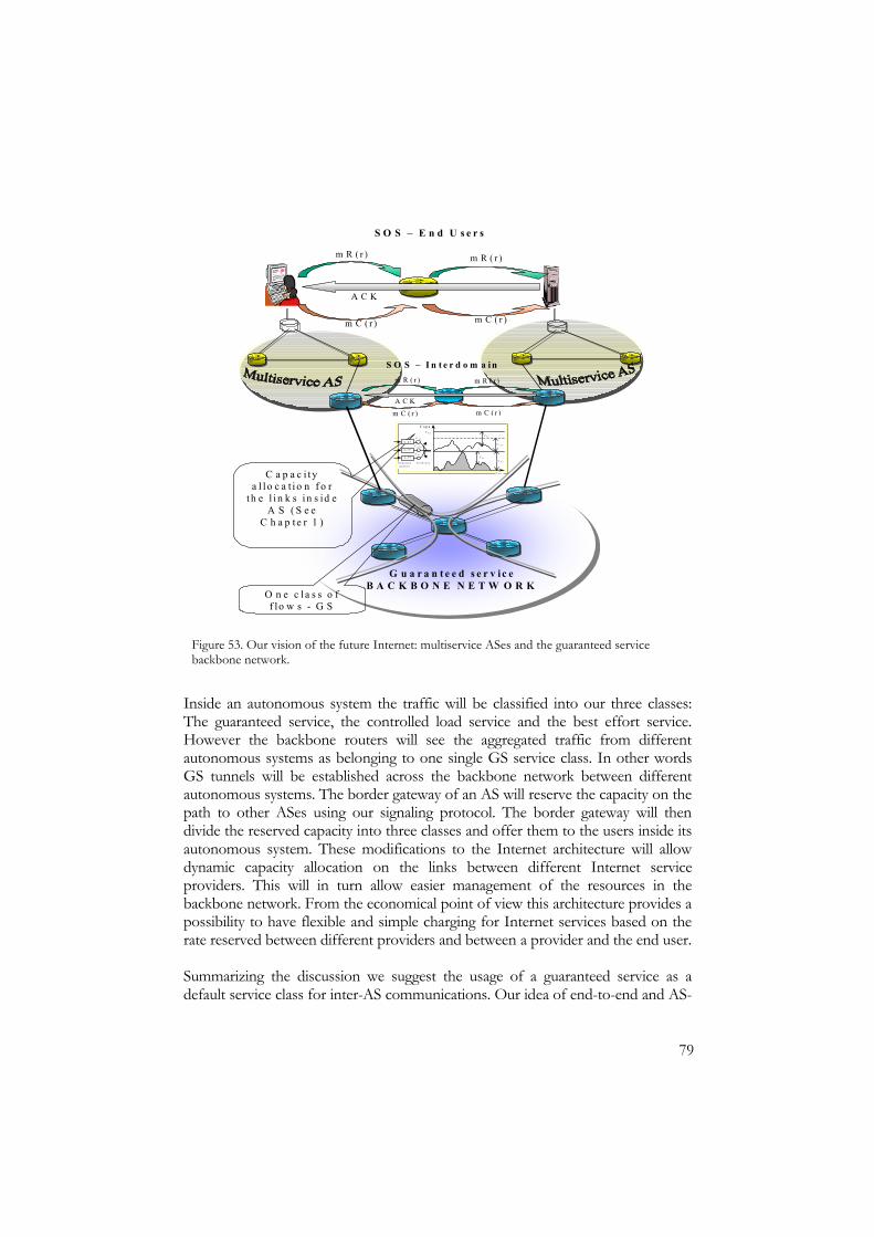
79
G u a r a n t e e d s e r v i c e B A C K B O N E N E T W O R K
m R ( r ) m R ( r )
m C ( r ) m C ( r )
A C K
S O S – E n d U s e r s
O n e c l a s s o f f lo w s - G S
C a p a c i t y a l l o c a t i o n f o r
t h e l i n k s i n s id e A S ( S e e
C h a p t e r 1 )
q _ g s
q _ c l s
q _ b e
S e p a r a t e q u e u e s
S c h e d u l i n g
C G S
C C L S
C B E
C a p ai t C l in k
T i m e
C B E
C B E
C C L S
C G S
m R ( r ) m R ( r )
A C K
m C ( r ) m C ( r )
S O S – I n t e r d o m a i n
Figure 53. Our vision of the future Internet: multiservice ASes and the guaranteed service backbone network.
Inside an autonomous system the traffic will be classified into our three classes: The guaranteed service, the controlled load service and the best effort service. However the backbone routers will see the aggregated traffic from different autonomous systems as belonging to one single GS service class. In other words GS tunnels will be established across the backbone network between different autonomous systems. The border gateway of an AS will reserve the capacity on the path to other ASes using our signaling protocol. The border gateway will then divide the reserved capacity into three classes and offer them to the users inside its autonomous system. These modifications to the Internet architecture will allow dynamic capacity allocation on the links between different Internet service providers. This will in turn allow easier management of the resources in the backbone network. From the economical point of view this architecture provides a possibility to have flexible and simple charging for Internet services based on the rate reserved between different providers and between a provider and the end user. Summarizing the discussion we suggest the usage of a guaranteed service as a default service class for inter-AS communications. Our idea of end-to-end and AS-

80
to-AS channels (circuits) will allow the Internet to provide a better quality of service to end customers, simplicity of management of inter-AS communication and clarify the issues of service level agreements between different ISPs. The usage of simple and identical mechanisms for the resource reservation on the end-users and inter-domains levels implies simplicity of implementation of our Internet architecture. The following issues need to be addressed while developing the idea of the “circuit switched” Internet: Adjustment of the signaling protocol for inter-AS communications, development of methods for capacity reservation between autonomous systems and allocation of the capacity reserved of the inter-AS channel inside an AS. Addressing the first issue, we need to separate the operations of the signaling protocol inside the ASes and in the backbone network. Once capacity is reserved on the inter-AS level, the backbone network must be transparent for the signaling messages that arrive from the individual end systems. One way to implement this is to tunnel the signaling messages from end-users across the established channel. This will effect in additional complexity of the border gateways. An alternative solution would be to encode signaling messages for the inter-AS reservations differently from those inside ASes. Another aspect that must be considered in detail is a method of capacity reservation on the inter-AS level. Assuming some initial reservation of the capacity between two ASes, how should a border gateway react if an incoming SOS reservation request is for more capacity than what is available? One solution is to use temporarily the part of the capacity which was allocated for traffic of other classes. As soon as this situation occurred the border gateways should extend the capacity for the GS channel. However, the way in which the temporal usage by GS connections of the capacity allocated to the CLS and BE traffic will affect their QoS characteristic must be additionally studied.
81
CHAPTER 5. CONCLUSIONS
In this thesis we presented the results of the development of a network mechanism that allows the Internet to provide a guaranteed service for real-time applications. The guaranteed service is intended for a broad class of real-time applications with strict requirements on the end-to-end delay and no tolerance to packet loss. We defined the guaranteed service class as is done in the integrated services architecture but used the idea of aggregate scheduling from the differentiated services framework. In order to obtain the above guarantees the applications utilize a simple signaling protocol to explicitly reserve the capacity on network links. The guarantees on the transmission capacity, bounded end-to-end delay and zero packet loss are enforced by a cascade of non-work-conserving schedulers at the output port of every router. Specifically this thesis focused on the analysis of the scheduling algorithm and the design and analysis of SOS, a sender oriented signaling protocol. We have developed a two-stage scheduling scheme where incoming aggregates are reshaped before entering the buffer of the output scheduler. We have shown experimentally that the presence of such shapers drastically decrease the maximum queuing delay in routers. We performed an analysis of our proposed architecture using network calculus and calculated the worst-case end-to-end queuing delay. As was shown the proposed scheduling provides a finite delay bound for the guaranteed service flows. The calculated size of buffers in the output port of core routers ensures lossless handling of the guaranteed service packets. We have presented a complete specification of a signaling protocol for unicast GS communications. Whilst designing the protocol’s operations we considered both the networks with stable routes and networks where routes may change. SOS has the following properties: It is sender oriented, it uses four types of messages to reserve, maintain and teardown a guaranteed service connection, the protocol does not use per-flow state in core routers and the simple operations allow the fast message processing. We have developed two fault-handling mechanisms. These make SOS tolerant to all types of signaling messages loss. We designed an encoding scheme for signaling messages in the current format of the IP packet header plus we have developed a re-routing recovery procedure for the GS connections.
82
5.1 Future work
The results obtained from the simulations showed suitability of the proposed architecture for real-time applications. However, the simulations are only an approximation of the reality, therefore our primary goal in future work is to observe the behavior of the guaranteed service mechanisms in real networks. For this purpose we are implementing the scheduling scheme and signaling protocol in Linux based routers and end systems. We intend to construct a test-bed network with enabled GS support and perform experiments with current real time applications. The design in this thesis was concerned only with unicast communication. Another direction of our work is to consider multicast GS flows. Another direction of our work is to consider the issues of security in our service architecture. The “guaranteed” nature of our service implies also protection of the established GS sessions from misbehaving users.

83
BIBLIOGRAPHY
[1] Defense Advanced Research Projects Agency, “Internet protocol”, RFC 791, IETF, September 1981.
[2] R. Braden, D. Clark, and S. Shenker, “Integrated services in the Internet architecture: an overview”, RFC1633, IETF, June 1994.
[3] J. Wroclavski, “Specification of the controlled-load network element service”, RFC 2211, IETF, September 1997.
[4] S. Shenker, C. Partridge, R. Guerin, “Specification of guaranteed quality of service”, RFC 2212, IETF, September 1997.
[5] S. Blake, D. Black, M. Carlson, E. Davies, Z. Wang, and W. Weis, “An architecture for differentiated services”, RFC 2475, IETF, December 1998.
[6] J. Heinanen, F. Baker, W. Weis, J Wroclavski, “Assured forwarding PHB group”, RFC 2597, IETF, June 1999.
[7] V. Jacobson, K. Nichols, K. Poduri, “An expedited forwarding PHB”, RFC 2598, IETF, June 1999.
[8] A. Banerjea, D. Ferrari, B. Mah, M. Moran, D. Verma, H. Zhang, “The tenet real-time protocol suit: design, implementation, and experiences”, IEEE/ACM Transactions on networking, Vol. 4, No. 1., February 1996.
[9] IETF Working group Integrated Services over Specific Link Layers (ISSLL), http://www.ietf.org/html.charters/issll-charter.html.
[10] N. Borg, E. Svanberg and O. Schelen, “Efficient multi-field Packet Classification for QoS purposes”, in Proc. of 7th International Workshop on Quality of Service (IWQoS’99), 1999.
[11] R. Braden, L. Zhang, S. Berson, S. Herzog, and S. Jamine, “Resource reservation protocol (RSVP)”, RFC 2205, IETF, September 1997.
[12] Y. Bernet, P. Ford, R. Yavatkar, F. Baker, L. Zhang, M. Speer, R. Braden, B. Davie, J. Wroclawski, E. Felstaine, “A framework for integrated services operation over diffserv networks”, RFC 2998, IETF, November 2000.
[13] F. Baker, C. Iturralde, F. Le Faucheur, B. Davie, “Aggregation of RSVP for IPv4 and IPv6 Reservations”, RFC 3175, IETF, September 2001.
[14] J. Harju, P. Kivimaki, “Co-operation and comparison of diffserv and intserv: performance measurements”, in Proc. of 25th Annual IEEE Conference on Local Computer Networks, 2000, pp. 177-186.
[15] IETF Working group Next Steps in Signaling (NSIS), http://www.ietf.org/html.charters/nsis-charter.html.
[16] P. Pan, and H. Schulzrinne, “YESSIR: a simple reservation mechanism for the Internet”, ACM Computer Communication Review, vol. 29, No. 2, April 1999.
[17] G. Feher, K. Nemeth, M. Maliosz, I. Cselenyi, J. Bergkvist, D.Ahlard, T. Engborg, “Boomerang - a simple protocol for resource reservation in IP networks”, IEEE Workshop on QoS Support for Real-Time Internet Application, June 1999.
84
[18] T. W. K. Chung, H. C. B. Chang, V. C. M. Leung, “Flow initiation and reservation tree (FIRST)”, IEEE Conference on Communications, Computers, and Signal Processing, pp. 361-364, 1999.
[19] A. Eriksson and C. Gehrman, “Robust and secure light-weight resource reservation for unicast IP traffic”, in Proc. of 6th IEEE International Workshop on Quality of Service (IWQoS 98), 1998, pp. 168-170.
[20] M. Menth and R. Martin, “Performance evaluation of the extensions for control message retransmissions in RSVP”, In Proc. of 7th IEEE International Workshop on Protocols for High Speed networks (PfHSN 2002), 2002, pp. 35-49.
[21] M. Karsten, “Experimental extensions to RSVP - remote client and one-pass signaling”, in Proc. of 9th IEEE International Workshop on Quality of Service (IWQoS 01), 2001.
[22] M. Karsten, J. Schmitt, N. Berier, and R. Steinmetz, “On the feasibility of RSVP as general signaling interface”, in Proc. of 1st COST 263 International Workshop on Quality of Future Internet Services (QoFIS 2000), 2000.
[23] L.Westberg, A. Csaszar, G. Karagiannis, A. Marquetant, D. Partian, O. Pop, V. Rexhepi, R. Szabo, A. Takacs, “Resource management in diffserv (RMD): a functionality and performance behavior overview”, In Proc. of 7th IEEE International workshop on Protocols for High-Speed Networks (PfHSN 2002), pp. 17-34, 2002.
[24] R. Guerin and A. Orda, “Networks with advance reservations: the routing prespective”, in Proc. of IEEE Infocom 2000, pp. 118-127.
[25] G. Apostolopoulos, R. Guerin, S. Kamat, A. Orda, S. Tripathi, “Intradomain QoS routing in IP networks: a feasibility and cost/benefit analysis”, IEEE Network, September 1999, pp. 42-54.
[26] ATM Forum, http://www.atmforum.com. [27] S. Nilsson and G. Karlsson, “IP-Address Lookup Using LC-Tries”, IEEE Journal
on Selected Areas in Communications, Vol. 17, No. 6, June 1999, pp. 1083-1092. [28] K. Nichols, V. Jacobson, L. Zhang, “A two-bit differentiated service architecture
for the Internet”, RFC 2638, IETF, July 1999. [29] B. Braden, D. Clark, J. Crowcroft, B. Davie, S. Deering, D. Estrin, S. Floyd, V.
Jacobson, G. Minshall, C. Partridge, L. Peterson, K. Ramakrishnan, S. Shenker, J. Wroclawski, L. Zhang, “Recommendations on Queue Management and Congestion Avoidance in the Internet”, RFC 2309, IETF, April 1998.
[30] A. Romanow and S. Floyd, “Dynamics of TCP Traffic over ATM Networks”, IEEE Journal on Selected Areas in Communications, V. 13 N. 4, May 1995, p. 633-641.
[31] R.L. Cruz. “A calculus for network delay. I. Network elements in isolation”, IEEE Transactions on Information Theory, Vol. 37 Issue 1, January 1991, pp. 114-131.
[32] R.L. Cruz, “A calculus for network delay. II. Network analysis”, IEEE Transactions on Information Theory , Vol. 37 Issue 1, January 1991, pp. 132-141.
[33] C. Chang, R.L. Cruz, J-Y. Le Boudec, P. Thiran, “A min, + system theory for constrained traffic regulation and dynamic service guarantees”, IEEE Transactions on Networking, Vol. 10 Issue 6, December 2002, pp. 805-817.
[34] A. Parekh and R. Gallager, “A generalized processor sharing approach to flow control in integrated services networks: the single-node case”, IEEE/ACM Transactions on Networking, Vol. 1, No 3, June 1993.
85
[35] A. Parekh and R. Gallager, “A generalized processor sharing approach to flow control in integrated services networks: the multiple node case”, IEEE/ACM Transactions on Networking, Vol. 2, No 2, April 1994.
[36] J. Y. Le Boudec, P. Thiran, Network Calculus, Springer Verlag LNCS 2050, June 2001.
[37] S. Golestani, “A self -clocked fair queuing scheme for broadband applications”, In Proc. of IEEE Infocom 1994, pp. 636-646.
[38] J. Bennett and H. Zhang, “WF2Q: Worst-case fair weighted queuing”, In Proc. of IEEE Infocom 1996, pp. 120-128.
[39] H. Zhang, “Service disciplines for guaranteed performance service in packet-switching networks”, Proceedings of IEEE, Vol. 83(10), pp. 1374-1396, October 1995.
[40] H. Zhang, “Providing end-to-end performance guarantees using non-work-conserving disciplines”, ACM Computer Communications: Special Issue on System Support for Multimedia Computing, 18(10), October 1995.
[41] S.J. Golestani, “A framing strategy for congestion management”, IEEE Journal on Selected Areas in Communications, vol. 97, September 1991, pp. 1064 -1077.
[42] D. Verma, H. Zhang, and D. Ferrari, “Guaranteeing delay-jitter bounds in packet switching networks”, in Proc. of Tricomm’91, pp. 35-46.
[43] F. Guillemin, P. Boyer, A. Dupuis, and L. Romoeuf, “Peak rate enforcement in ATM networks”, in Proc. of IEEE Infocom 1992, pp. 753-758.
[44] J. Cobb, “Preserving quality of service guarantees in spite of flow aggregation”, IEEE/ACM Transactions on Networking, vol.10, February 2002.
[45] A. Charny and J-Y Le Boudec, “Delay bounds in a network with aggregate scheduling”, in Proc. of 1st COST 263 International Workshop on Quality of Future Internet Services (QoFIS 2000), 2000.
[46] J-Y Le Boudec, “A proven delay bound for a network with aggregate scheduling”, EPFL-DCS Technical Report DSC2000/002, http://ica1www.epfl.ch/PS_files/ds2.pdf.
[47] L. Veltri, “Delay calculus for differentiated services networks”, in Proc. of IEEE International Conference on Communications (ICC 2001), pp. 2912-2917, 2001.
[48] M. Andrews, “Instability of FIFO in session-oriented networks”, In eleventh Annual ACM-SIAM Symposium on Discrete Algorithms (SODA 2000), January 2000.
[49] K. Iida, K. Kawahara, T. Takine, Y. Oie, “Performance analysis of flow aggregation of constant bit rate type traffic at ingress router”, In Proc. of IEEE Globecom’99, pp. 92-99, 1999.
[50] H. Fu and E. Knightly, “Aggregation and scalable QoS: a performance study”, in Proc. of 9th IEEE International Workshop on Quality of Service (IWQoS 01), 2001.
[51] G. Karlsson, F. Orava, “The DIY approach to QoS”, in Proc. 7th IEEE International Workshop on Quality of Service (IWQoS 99), 1999, pp. 6-8.
[52] M. Mowbray, G. Karlsson, and T. Köhler, “Capacity reservation for multimedia traffics”, Distributed Systems Engineering, vol. 5, 1998, pp. 12-18.
[53] V. Elek, G. Karlsson, and R. Rönngren, “Admission control based on end-to-end measurements”, in Proc. of IEEE Infocom 2000, pp. 623-630.
86
[54] I. Mas Ivars, G. Karlsson, “PBAC: probe based admission control”, in Proc. of 2nd COST 263 International Workshop on Quality of Future Internet Services (QoFIS 2001), pp. 97-109, 2001.
[55] I. Mas Ivars, V. Fodor, G. Karlsson, “Probe-based admission control for multicast”, in Proc. 10th IEEE International Workshop on Quality of Service (IWQoS 02), pp. 97-109, 2002.
[56] E. Ossipov, G. Karlsson, “A simplified guaranteed service for the Internet”, in Proc. of 7th IEEE International Workshop on Protocols for High-Speed Networks 2002, pp. 147-163, 2002.
[57] E. Ossipov, G. Karlsson, “SOS: Sender oriented signaling for simplified guaranteed service”, In Proc. of Third International Workshop on Quality of Future Internet Services (QoFIS’02), pp. 100 – 114, 2002.
[58] Network Simulator NS-2, http://www.isi.edu/nsnam/ns [59] F. Le Faucheur, L. Wu, B. Davie, S. Davari, P. Vaananen, R. Krishnan, P. Cheval, J.
Heinanen, “Multi-protocol label switching (MPLS) support of differentiated services”, RFC 3270, IETF, May 2002.
[60] L. Delgrossi, L. Berger, “Internet stream protocol version 2 (ST2) protocol specification – version ST2+”, RFC 1819, IETF, August 1995.
[61] CIP Working Group, “Experimental Internet stream protocol, version 2 (ST-II)”, RFC 1190, IETF, October 1990.
[62] J. Schmitt, M. Karsten, and R. Steinmetz, “On the Aggregation of Guaranteed Service Flows”, Computer Communications (Special Issue on QoS sensitive Network Applications and Systems), pp. 2-18, January 2001.
[63] D. Mills, “Simple Network Time Protocol (SNTP) Version 4 for IPv4, IPv6, and OSI”, RFC 2030, IETF, October 1996.
[64] K. Nichols, S. Blake, F. Baker, D. Black, “Definition of the differentiated services field (DS field) in the IPv4 and IPv6 headers”, RFC 2474, IETF, December 1998.
[65] The official web site of Telecost, a producer of Call Management, Mediation and Billing software for the Telecommunications industry http://www.telecost.co.uk/pages/CallDurationLength.htm
[66] J. Moy, “OSPF version 2”, RFC 2328, IETF, April 1998.
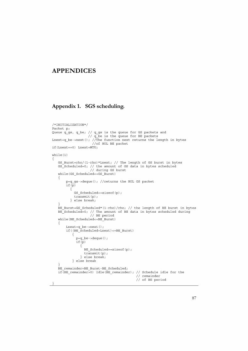
87
APPENDICES
Appendix 1. SGS scheduling.
/*INITIALIZATION*/Packet p;Queue q_gs, q_be; // q_gs is the queue for GS packets and
// q_be is the queue for BE packetsLnext=q_be->next(); //The function next returns the length in bytes
//of HOL BE packetif(Lnext==0) Lnext=MTU;
while(1){
GS_Burst=rho/(1-rho)*Lnext; // The length of GS burst in bytesGS_Scheduled=0; // the amount of GS data in bytes scheduled
// during GS burstwhile(GS_Scheduled<=GS_Burst){
p=q_gs->deque(); //returns the HOL GS packetif(p){GS_Scheduled+=sizeof(p);transmit(p);
} else break;}BE_Burst=GS_Scheduled*(1-rho)/rho; // the length of BE burst in bytesBE_Scheduled=0; // The amount of BE data in bytes scheduled during
// BE periodwhile(BE_Scheduled<=BE_Burst){
Lnext=q_be->next();if((BE_Scheduled+Lnext)<=BE_Burst)
{p=q_be->deque();if(p){BE_Scheduled+=sizeof(p);transmit(p);
} else break;} else break
}BE_remainder=BE_Burst-BE_Scheduled;if(BE_remainder>0) Idle(BE_remainder); // Schedule idle for the
// remainder// of BE period
}
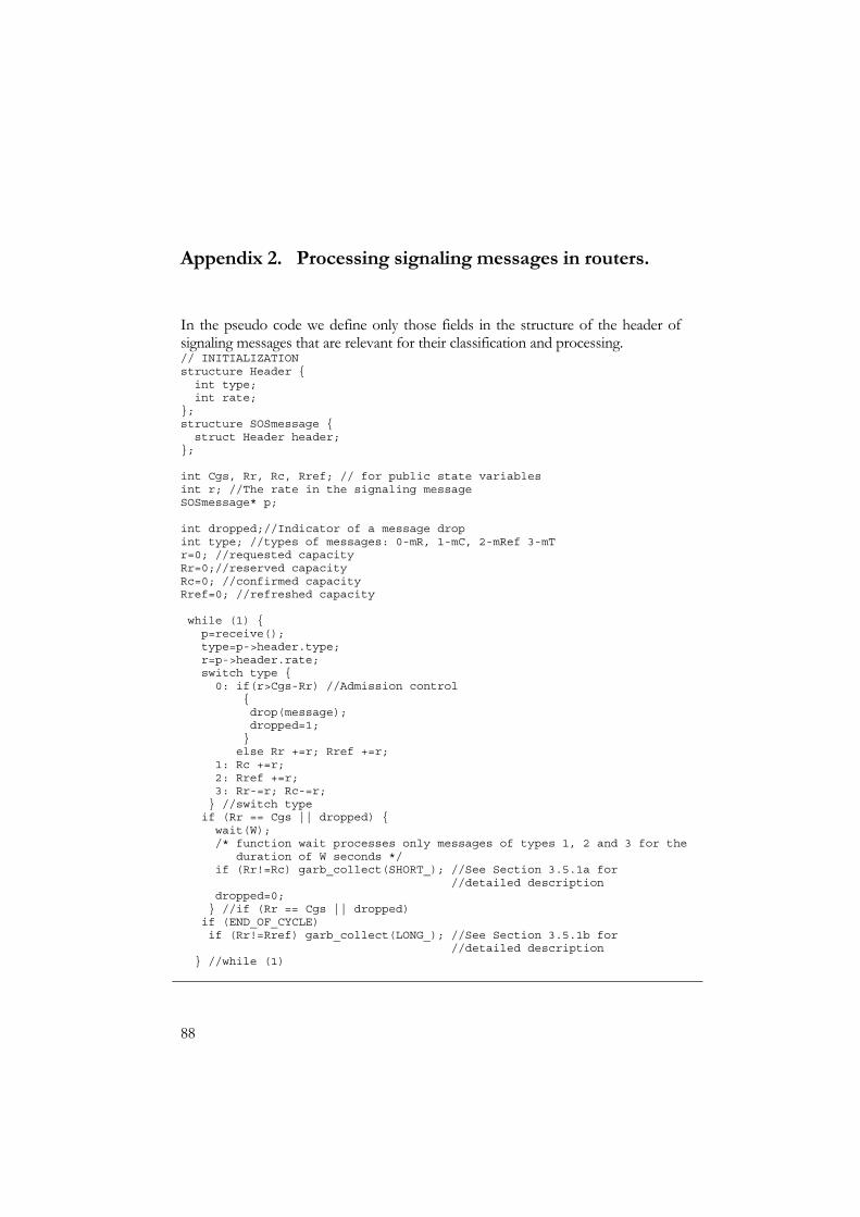
88
Appendix 2. Processing signaling messages in routers.
In the pseudo code we define only those fields in the structure of the header of signaling messages that are relevant for their classification and processing. // INITIALIZATIONstructure Header {int type;int rate;
};structure SOSmessage {struct Header header;
};
int Cgs, Rr, Rc, Rref; // for public state variablesint r; //The rate in the signaling messageSOSmessage* p;
int dropped;//Indicator of a message dropint type; //types of messages: 0-mR, 1-mC, 2-mRef 3-mTr=0; //requested capacityRr=0;//reserved capacityRc=0; //confirmed capacityRref=0; //refreshed capacity
while (1) {p=receive();type=p->header.type;r=p->header.rate;switch type {0: if(r>Cgs-Rr) //Admission control
{drop(message);dropped=1;}else Rr +=r; Rref +=r;
1: Rc +=r;2: Rref +=r;3: Rr-=r; Rc-=r;} //switch typeif (Rr == Cgs || dropped) {wait(W);/* function wait processes only messages of types 1, 2 and 3 for the
duration of W seconds */if (Rr!=Rc) garb_collect(SHORT_); //See Section 3.5.1a for
//detailed descriptiondropped=0;} //if (Rr == Cgs || dropped)if (END_OF_CYCLE)if (Rr!=Rref) garb_collect(LONG_); //See Section 3.5.1b for
//detailed description} //while (1)
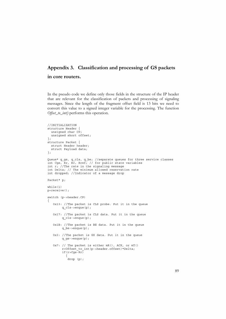
89
Appendix 3. Classification and processing of GS packets in core routers.
In the pseudo code we define only those fields in the structure of the IP header that are relevant for the classification of packets and processing of signaling messages. Since the length of the fragment offset field is 13 bits we need to convert this value to a signed integer variable for the processing. The function Offset_to_int() performs this operation.
//INITIALIZATIONstructure Header {unsigned char CP;unsigned short offset;
};structure Packet {struct Header header;struct Payload data;
};
Queue* q_gs, q_cls, q_be; //separate queues for three service classesint Cgs, Rr, Rc, Rref; // for public state variablesint r; //The rate in the signaling messageint Delta; // The minimum allowed reservation rateint dropped; //Indicator of a message drop
Packet* p;
while(1)p=receive();
switch (p->header.CP){
0x13: //The packet is CLS probe. Put it in the queueq_cls->enque(p);
0x17: //The packet is CLS data. Put it in the queueq_cls->enque(p);
0x1B: //The packet is BE data. Put it in the queueq_be->enque(p);
0x3: //The packet is GS data. Put it in the queueq_gs->enque(p);
0x7: // The packet is either mR(), ACK, or mT()r=Offset_to_int(p->header.offset)*Delta;if(r>Cgs-Rr){drop (p);

90
dropped=1; //mR() is dropped}
elseRr+=r;
if(Rr==Cgs || dropped){wait(W);/*function wait process only mC, mRef, and mT for theduration of W seconds */
if (Rr!=Rc) garb_collect(SHORT_); //See Section 3.5.1a//for details
dropped=0;}; //if (Rr == Cgs || dropped)if (END_OF_CYCLE)if (Rr!=Rref) garb_collect(LONG_); //See Section 3.5.1b for
//detailed descriptionq_gs->enque(p);
0xB: // The packet is mC()r=Offset_to_int(p->header.offset)*Delta;Rc+=r;q_gs->enque(p);
0xF: // The packet is mRef()r=Offset_to_int(p->header.offset)*Delta;Rc+=r;q_gs->enque(p);
}//end switch}// end while(1)
