the design and construction of new mizen head … · design and construction of new mizen head...
TRANSCRIPT

The Design and Construction of New Mizen Head Footbridge
Murt Coleman, BE CEng FIEI, Chartered Engineer Managing Director, Carillion Irishenco Ltd. Enda Collery, BA BAI CEng MIEI, Chartered Engineer
Contracts Manager, Carillion Irishenco Ltd. Eoghan Lehane, BE Eur Ing CEng MIEI MCIWEM, Chartered Engineer
Civil Engineering and Property Manager, Commissioners of Irish Lights Brendan Minihane, BE Eur Ing CEng MIEI, Chartered Engineer
Project Resident Engineer, Cork County Council Ross O’Donovan, Dip Eng BEng CEng MIEI, Chartered Engineer
Senior Resident Engineer, RPS Consulting Engineers Ltd. Noel O’Keeffe, BE Eur Ing CEng FIEI MICE, Chartered Engineer
County Engineer, Cork County Council Kevin Power, BE CEng FIEI MICE MCIWEM, Chartered Engineer
Director, RPS Consulting Engineers Ltd. Kieran Ruane*, BE MSc(Eng) CEng MIStructE MIEI MICE, Chartered Engineer
Technical Director, RPS Consulting Engineers Ltd.
Paper first presented to a joint meeting of Engineers Ireland, Institution of Structural Engineers and The Irish Concrete Society in Cork on 08.03.2011. *Corresponding author: Tel +353 (0) 21 4665900, [email protected].


Design and Construction of New Mizen Head Footbridge Paper first presented to Engineers Ireland, IStructE and ICS in Cork on 08.03.2011
Page 1
The Design and Construction of New Mizen Head Footbridge
Overview Mizen Head Footbridge in County Cork is a reinforced concrete through-arch structure spanning 50m. The original structure was completed in 1909. After 100 years of service the bridge was demolished and reconstructed in 2009/10. This paper describes the design and construction challenges of safely demolishing and reconstructing the bridge in a difficult site location.
Figure 1: Mizen Head Footbridge (2004) Mizen Head Footbridge Mizen Head Footbridge is shown in Figure 1. The bridge provided access to a lighthouse on a tiny island, Cloghán, at the tip of Mizen Head in southwest Cork. The original structure was commissioned by the Commissioners of Irish Lights (CIL). The structural form was chosen from a design competition held in the early 1900’s. The entries to this competition are held in the CIL archives and on display in the Visitors’ Centre at Mizen Head. The winning entry was a design by Mr. Noel Ridley of Westminster, London. It consisted of a pair of parabolic arch ribs spanning 50m which supported a pedestrian deck, the deck being suspended by vertical hangers from the ribs in the central section. In the quarter spans the deck was supported by the ribs via a series of trestles. The ribs were 1.6m apart in the central section where the deck was suspended. Where the ribs intersected the deck they flared out so that the ribs were 3.7m apart at the springing points. The ribs were cross-braced below deck level to provide an inherently stable structure.
On the 18th of October 1907, sanction was given for the erection of a reinforced concrete bridge to give access to the island. Construction of the bridge commenced in 1908 and was completed in 1909. The Contractor was Alfred Thorne and Sons of Westminster, London and the contract cost was £1,272. The original bridge comprised both precast and in-situ reinforced concrete elements and it was considered an early example of precast concrete construction1. The arch ribs were constructed in stages both onshore and in-situ2,3. The initial rib cross section was an open precast concrete trough to allow launching of the ribs. The open cross-section allowed precast concrete trestles and deck edge beams to be added before the ribs were completed with in-situ concrete. The bridge deck and the hangers were cast in-situ. The reinforcement in the structure was in the form of round bars, rectangular bars and sheets of steel folded in a corrugated manner. The bridge was constructed in the era of proprietary reinforced concrete systems and the system used was the Ridley-Cammell system. Figure 2 shows the structural elements of the bridge. Figure 3 shows an image of the original bridge under construction with the use of an overhead wire ropeway.
Figure 2: Structural elements of the bridge
Figure 3: The original bridge under construction

Design and Construction of New Mizen Head Footbridge Paper first presented to Engineers Ireland, IStructE and ICS in Cork on 08.03.2011
Page 2
The Bridge Site The bridge spans a sea gorge between the mainland at Mizen Head and the tiny island of Cloghán. The soffit of the bridge is some 45m above the bottom of the gorge. Access to the bridge site is difficult. Vehicle access is possible to within 300m of the mainland abutment. Thereafter, access is only available along a steeply inclined footway which is less than 1m wide along a substantial part of its length (Figure 4).
Figure 4: Access to the footbridge The local geology of the site has always attracted interest. Purple coloured horizons flank the footbridge. These horizons comprise thinly bedded sandstone units with interbedded mudstone giving the rocks a purplish hue. The rocks strike to the northeast, with well developed cleavage and quartz veining, parallel to bedding planes. Bedding is noted to be both horizontal and steeply dipping (almost vertical) at different locations. The U-shaped limbs of the Crookhaven Syncline are clearly identifiable from the footbridge. Origins of the Scheme For over 100 years, CIL has carried out maintenance activities on the bridge. A maintenance contract was undertaken in 2000 for repainting the bridge and carrying out concrete repairs. An inspection by CIL engineers at this time revealed areas of spalled concrete and severe reinforcement corrosion, particularly at a joint between a deck hanger and the northern edge beam. In 2002, CIL appointed RPS (then M.C. O’Sullivan and Company Ltd.) to conduct an inspection and structural assessment of the footbridge. Specific information on the structure was collected by material tests, observations and geometrical surveys. This information helped to establish the condition of the structure and provide material and geometric parameters for analytical models and for maintenance, repair or strengthening scheme development. The defects noted during the inspection may be summarised as rust staining, areas of hollow sounding concrete, cracking and localised
areas of missing concrete. All the defects noted were related to corroding reinforcement. No defects caused by structural actions were observed. In general, the visual inspection of the bridge found it to be in good condition given its age and its location in an exposed site4. This was due to the quality of the original construction and to CIL who have regularly maintained and repainted the bridge over its lifetime.
Figure 5: Inspection by roped access in 2002 Material tests were used to determine the integrity and strength of the concrete and to investigate reinforcement corrosion mechanisms. Both non-destructive and destructive tests were used ranging in complexity from hammer tap surveys to petrographic examination. BA 35/905 presents information on these and other tests with useful references. Table 1 summarises the test results. Test Summary Comment
Cover meter survey.
Varied from minimum of 31mm to maximum of 85mm with an average of 49.1mm.
Good cover meter readings throughout, readings corresponded to steel locations indicated on construction drawings.
Depth of carbonated concrete.
Typically measured at 1mm.
Low carbonation depth expected due to bridge location.
Depth of coating applied.
Typically 2mm. Refers to bituminous coating and paint layers previously applied to the concrete members.
Chloride content.
Varied from minimum of 1.92% to maximum of 4.06% with an average of 2.73%.
Very high levels of chloride recorded throughout the structure.
Schmidt hammer test for concrete consistency.
Varied from minimum of 26 N/mm2 to maximum of 51 N/mm2 with an average of 34.6N/mm2.
Consistent readings throughout the structure. Good correlation between readings and core strengths.
Concrete core removal and compression testing.
Three cores removed and tested. Strengths recorded: 70.3 N/mm2, 46.4 N/mm2 and 72.9 N/mm2.
Cores removed and tested by UCD in 1990.
Concrete core removal and compression testing.
One core removed and found to have a strength of 27.5 N/mm2.
Core removed during 2002 inspection.
Concrete core removal and petrographic testing.
One core removed for petrographic testing and remains of other core also tested petrographically after compression test.
Petrographic examination indicated that the concrete was made to a specification, it was well compacted during construction, it was made with suitable materials and it was generally found to be a high quality concrete.
Table 1: Materials test results 2002

Design and Construction of New Mizen Head Footbridge Paper first presented to Engineers Ireland, IStructE and ICS in Cork on 08.03.2011
Page 3
Concrete was broken out locally in two hangers to examine the condition of the reinforcement. The reinforcement in the first break-out was found to be in very good condition. The reinforcement in the second breakout was found to have disintegrated in to a fine black dust without the formation of expansive product (Figure 6). This is an unusual form of steel anaerobic corrosion and it is the subject of ongoing research. Figure 6: Breakout of Hanger N19 in 2002. Original flat bar reinforcement had disintegrated in to a fine black dust without expansive product. Two 105mm diameter cores were taken from the deck of the bridge. One of these cores was compression tested and found to have an equivalent cube strength of 27.5N/mm2. Three cores removed from the arch ribs in 19907 were compression tested and found to have equivalent cube strengths of 70.3, 46.4 and 72.9N/mm2. Petrographic examination was carried out on two core samples taken from the structure. The coarse aggregate used in the deck construction was dominated by crushed greywacke and sandstone particles having a nominal maximum size of 14mm. The aggregate in the coarse fraction was probably locally derived. The fine aggregate contained abundant shell fragments, which were derived from a marine source, probably a beach sand (Figure 7). Samples of sand were taken from nearby Barley Cove during a visit to the site and examined in the laboratory using the petrological microscope. This material closely resembled the shell fragments found in the deck concrete and given the close proximity of the beach to the bridge it is likely that Barley Cove was the source of fine aggregate used in the deck.
Figure 7: Petrographic analysis of the original bridge concrete showing presence of sea shells No evidence of damage due to alkali-aggregate action was found in the petrographic examination, although traces of gel were present in voids in the paste. Examination of a thin section taken from a portion of the core sample showed fine cracks running through aggregate particles into the cement paste. These were found to contain alkali silicate gel and indicated that an expansive reaction had taken place between the greywacke aggregate and alkalies in the paste, causing very localised damage to the concrete in the area where the core had been taken. This is considered to be the only reported example of alkali-aggregate reaction in Ireland to date. In summary, chloride content levels were very high throughout the structure. This did not affect the integrity of concrete directly but it provided a mechanism for reinforcement corrosion to occur. Evidence of damage to concrete caused by the expansive product of reinforcement corrosion was clear in the inspection. Defects ranged from areas of hollow concrete where corrosion had caused delamination of the cover zone to areas of spalled concrete. Carbonation levels were very low. Based on the petrographic examination, low levels of alkali-aggregate reaction, low carbonation levels, high chloride levels, and strength estimates from cores and Schmidt hammer tests, it was concluded that the concrete, excluding the concrete in the cover zone, was of a sound nature. Based on the original construction drawings and the information gathered during the principal inspection, RPS carried out a finite element assessment of the structure (Figure 8). Structural member stiffnesses were calculated neglecting the cover layer concrete. Structural member resistances were calculated using half the reinforcement indicated in the construction drawings. The results indicated that the structure was adequate for continued use due to good reserves of structural resistance to applied dead and live loading effects.

Design and Construction of New Mizen Head Footbridge Paper first presented to Engineers Ireland, IStructE and ICS in Cork on 08.03.2011
Page 4
Figure 8: Part of the finite element model used for bridge assessment However, given that the central suspended span of the deck was relying on reinforced concrete hangers in direct tension and given the high chloride induced steel corrosion throughout the structure, it was recommended that the hangers be strengthened and that measures be taken to halt the corrosion of reinforcement in the structure. A monitoring regime was placed on the structure to allow regular inspections at six-monthly intervals. In 2004, RPS produced a Preliminary Report for Strengthening and Repair of the Mizen Head Footbridge. It was recommended that the hangers be reinforced with Near Surface Mounted Fibre Reinforced Polymer (NSM FRP) bars, that concrete repairs be undertaken to repair defects on the structure and that a cathodic protection system be installed on the structure to stall the rate of reinforcement corrosion. However, it was noted that the suitability of the structure to receive a cathodic protection system would need to be confirmed by specialist testing before a definite recommendation could be made. In February 2005, electrical continuity testing of reinforcement in the structure was undertaken to assess the feasibility of providing a cathodic protection system for the structure. The specialist testers concluded that there was a limited amount of reinforcement continuity within the arch ribs and within some hangers but that there was no general continuity of reinforcement steel within the structure, either between structural elements or within individual elements. Following the issue of the Electrical Continuity Testing Report to CIL, the Mizen Footbridge was closed to pedestrian traffic. In June 2005, RPS under the direction of CIL procured an access scaffold for the bridge. The scaffold was supported directly from the arch ribs only and provided an independent bridge deck for the structure. The scaffold allowed access to be maintained at Mizen Head until a permanent solution was developed (Figure 9). It was expected that the scaffold would have a lifespan in the region of 3 to 5 years.
Figure 9: Temporary access scaffold supported directly from the arch ribs erected in June 2005. Detailed Scheme Development A revised Preliminary Report was issued by RPS to CIL in September 2005. The following solutions were considered:
• Option 1: A strengthening and repair scheme which involved an initial strengthening and repair of the arch ribs and rib braces followed by a sequential removal and replacement of the remaining elements of the deck superstructure. The mass concrete foundations at the arch springing points and deck ends would be retained.
• Option 2: A scheme which initially
involved the construction of new arch ribs (parallel to and outside the existing ribs) using the existing ribs (strengthened if required) as falsework, followed by the sequential demolition of the existing bridge, followed by the construction of trestles edge beams, hangers, and the deck slab. This scheme produced a replica of the existing bridge though the deck would be 700mm wider. The mass concrete foundations at the arch springing points and deck ends would be retained.
• Option 3: A scheme which involved
replacing lost steel throughout the structure with small diameter FRP (Fibre Reinforced Polymer) bars using the Near Surface Mounted (NSM) method followed by a large concrete repair scheme.
Various factors fed in to the selection of the preferred option. These included heritage considerations, cost, environmental issues, ease of construction, health and safety, and durability.

Design and Construction of New Mizen Head Footbridge Paper first presented to Engineers Ireland, IStructE and ICS in Cork on 08.03.2011
Page 5
Option 2 was recommended as the preferred option as it maintained the current appearance and form of the bridge, it gave the best long term solution and provided an economic solution which could be built safely with minimal impact on the environment. Figure 10 outlines the solution.
Figure 10: Sectional elevations through the bridge indicating the solution to use the existing ribs as falsework for the construction of new ribs. The new ribs would then be used to support demolition works on the old bridge. Detailed design of this scheme was progressed by RPS under the direction of CIL in 2006. Specific measures to address durability were incorporated into the design. These included:
• Use of ground granulated blast furnace slag (GGBS) cement. The cement to be Ordinary Portland Cement with a GGBS replacement level of 50%. The concrete to be Grade C40/50 to IS EN 206.
• All exposed formed concrete surfaces to receive an F3 finish as described in the NRA Specification for Road Works. This is a high quality finish and it precludes the use of internal formwork ties and embedded metal formwork supports.
• All reinforcement used during construction to be stainless steel ribbed Grade 500 conforming to BS 6744:2001. The stainless steel grade to be Type 1.4301 to IS EN 10088.
• Any other exposed or non-exposed metallic elements provided as part of the works, such as parapet mesh panels, to be manufactured from stainless steel Type 1.4301 to IS EN 10088.
• The bridge deck to receive a combined anti-skid surfacing and waterproofing coat.
• Careful detailing of all elements to shed water from the structure.
• Use of trial panels to allow the Contractor to develop his construction proposals for the complex bridge geometry in advance of construction proper (Figures 11 and 13).
The replacement structure was designed as a two-pinned arch. Analysis was undertaken using the LUSAS finite element system and design was undertaken to British Standard BS5400. The live loading consisted of 5kN/m2 nominal pedestrian loading and a maintenance vehicle load case. Tender documents were prepared in accordance with the newly issued Department of Finance Public Works Contract Form for Civil Engineering Works Designed by the Employer.
Figure 11: Trial panel comprising braced arch rib section at trestle support.

Design and Construction of New Mizen Head Footbridge Paper first presented to Engineers Ireland, IStructE and ICS in Cork on 08.03.2011
Page 6
Tender Process Tender documents were issued to four prequalified contractors in November 2006. Three tenders were returned in December 2006. Tenders ranged from €2.02m to €4.01m (excluding VAT). All tenders were in excess of the budget provision. Tenders were submitted at the peak of the construction boom and there was uncertainty whether a contract agreement based on the tender would deliver value for money. The tender process was closed at this point. Alternative procurements strategies were examined in early 2007. These included Early Contractor Involvement and the Competitive Dialogue Procurement Process. CIL had successfully utilised the Competitive Dialogue Process on a different project and a new procurement process using this method was commenced in late 2007. The Competitive Dialogue Procurement Procedure is prescribed in SI 329/2006 “European Communities (Award of Public Authorities’ Contracts) Regulations 2006”. The procedure involves a contracting authority engaging in a dialogue with candidates, the aim of which is to identify and define the means best fitted to satisfy its needs. The dialogue may be conducted in a number of different stages which allows a contracting authority to reduce the number of solutions and/or eliminate tenderers during the dialogue phase. The dialogue continues until the contracting authority can identify the solution(s) meeting its needs. At the end of the dialogue, a contracting authority formally concludes the dialogue and invites candidates to submit final and complete tenders on the basis of the solution(s) presented and specified during the dialogue. Following a prequalification process, four contractors were selected to proceed to the Competitive Dialogue Process. Letters were issued to the candidates in December, 2007. The letter invited candidates to identify and define the appropriate solution for the existing bridge replacement in accordance with previous documentation issued for the prequalification process and the following guidelines:-
• “The preferred replacement solution is a replica of the current structure with a slightly wider deck constructed in high durability concrete either reinforced, precast or post / pre-tensioned or a combination of some or all of the options for a design life of 120 years.
• Taking into account possible
restrictions on funding and value for money requirements, consideration
will also be given to the following replacement solutions:-
- A 120 year design life
structure of any structural form and material capable of providing a safe and stable access to the island in weather conditions up to gale force.
- Similar to immediately above but with a 50 year design life.”
The candidates developed proposals which were discussed at individual competitive dialogue meetings. Proposals included stressed ribbon bridges, FRP bridges, carbon steel bridges and high quality stainless steel bridges. Detailed construction proposals were discussed including a proposal from Irishenco to ‘build a bridge to build a bridge’. The Competitive Dialogue Process was closed when each candidate was informed whether his alternative proposal was deemed acceptable or otherwise to the Employer based on the criteria outlined in the tender documentation. Candidates were then asked to submit their financial tenders for the preferred solution (the reinforced concrete replica structure) and/or their alternative proposal where appropriate. Four tenders were received in total, with sums ranging from €1.5m to €2.4m (excluding VAT). These comprised three tenders for the preferred solution and one for an acceptable alternative solution. On completion of the tender assessment process, a recommendation was made that the Contract be awarded to Irishenco for €1.5m (excluding VAT) for the construction of a replica structure in reinforced concrete. Funding for the project was provided by Fáilte Ireland, Cork County Council and the Commissioners of Irish Lights. Under an agreement between Cork County Council and CIL, Cork County Council undertook the role of Employer and entered in to agreement with Irishenco in September 2009 for the demolition and reconstruction of the bridge under the Department of Finance Public Works Contract Form for Civil Engineering Works Designed by the Employer. Construction Stage Works commenced in October 2009 with measures to improve access to the bridge. There was limited scope to widen the lower reaches of the footway to the mainland abutment. However, the upper reaches of the footway were locally widened to allow limited access for delivery vehicles and construction plant. The maximum plant size which could access the bridge site is shown in Figure 12.
Design and Construction of New Mizen Head Footbridge Paper first presented to Engineers Ireland, IStructE and ICS in Cork on 08.03.2011
Page 7
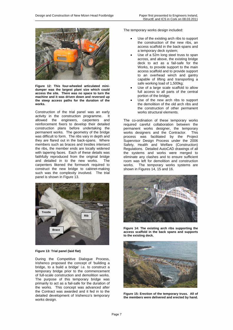
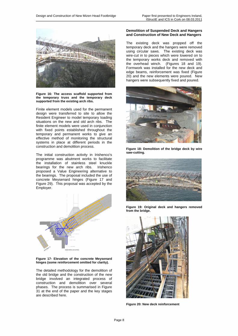
Figure 12: This four-wheeled articulated mini-dumper was the largest plant size which could access the site. There was no space to turn the machine and it was driven down and reversed up the steep access paths for the duration of the works. Construction of the trial panel was an early activity in the construction programme. It allowed the engineers, carpenters and reinforcement fixers to develop their detailed construction plans before undertaking the permanent works. The geometry of the bridge was difficult to form. The ribs vary in depth and they are flared out in the back-spans. Where members such as braces and trestles intersect the ribs, the member ends are locally widened with tapering faces. Each of these details was faithfully reproduced from the original bridge and detailed in to the new works. The carpenters likened the formwork required to construct the new bridge to cabinet-making such was the complexity involved. The trial panel is shown in Figure 13.
Figure 13: Trial panel (laid flat) During the Competitive Dialogue Process, Irishenco proposed the concept of ‘building a bridge, to a build a bridge’ i.e. to construct a temporary bridge prior to the commencement of full-scale construction and demolition works. The purpose of this temporary bridge was primarily to act as a fail-safe for the duration of the works. This concept was advanced after the Contract was awarded and it fed in to the detailed development of Irishenco’s temporary works design.
The temporary works design included:
• Use of the existing arch ribs to support the construction of the new ribs, an access scaffold in the back-spans and a temporary deck system;
• Use of a 52m long steel truss to span across, and above, the existing bridge deck to act as a fail-safe for the Works, to provide support to the main access scaffold and to provide support to an overhead winch and gantry capable of lifting and transporting a safe working load of 1,500kg;
• Use of a large scale scaffold to allow full access to all parts of the central portion of the bridge;
• Use of the new arch ribs to support the demolition of the old arch ribs and the construction of other permanent works structural elements.
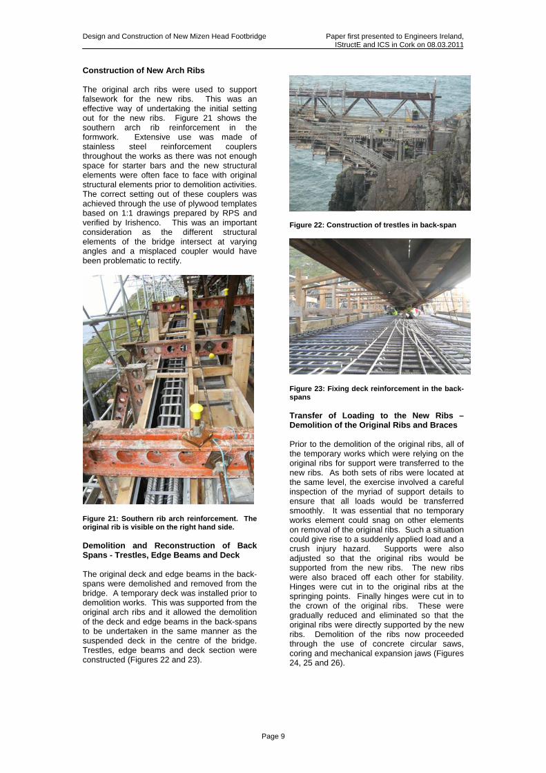
The co-ordination of these temporary works required careful collaboration between the permanent works designer, the temporary works designers and the Contractor. This process was facilitated by the Project Supervisor Design Process under the 2006 Safety, Health and Welfare (Construction) Regulations. Detailed AutoCAD drawings of all the systems and works were merged to eliminate any clashes and to ensure sufficient room was left for demolition and construction works. The temporary works systems are shown in Figures 14, 15 and 16.
Figure 14: The existing arch ribs supporting the access scaffold in the back spans and supports to the existing deck.
Figure 15: Erection of the temporary truss. All of the members were delivered and erected by hand.
Brace
Rib Trestle
Design and Construction of New Mizen Head Footbridge Paper first presented to Engineers Ireland, IStructE and ICS in Cork on 08.03.2011
Page 8
Figure 16: The access scaffold supported from the temporary truss and the temporary deck supported from the existing arch ribs. Finite element models used for the permanent design were transferred to site to allow the Resident Engineer to model temporary loading situations on the new and old arch ribs. The finite element models were used in conjunction with fixed points established throughout the temporary and permanent works to give an effective method of monitoring the structural systems in place at different periods in the construction and demolition process. The initial construction activity in Irishenco’s programme was abutment works to facilitate the installation of stainless steel knuckle bearings for the new arch ribs. Irishenco proposed a Value Engineering alternative to the bearings. The proposal included the use of concrete Meysenard hinges (Figure 17 and Figure 29). This proposal was accepted by the Employer.
Figure 17- Elevation of the concrete Meysenard hinges (some reinforcement omitted for clarity). The detailed methodology for the demolition of the old bridge and the construction of the new bridge involved an integrated process of construction and demolition over several phases. The process is summarised in Figure 31 at the end of the paper and the key stages are described here.
Demolition of Suspended Deck and Hangers and Construction of New Deck and Hangers The existing deck was propped off the temporary deck and the hangers were removed using circular saws. The existing deck was wire-cut in to pieces which were lowered on to the temporary works deck and removed with the overhead winch. (Figures 18 and 19). Formwork was installed for the new deck and edge beams, reinforcement was fixed (Figure 20) and the new elements were poured. New hangers were subsequently fixed and poured.
Figure 18: Demolition of the bridge deck by wire saw-cutting.
Figure 19: Original deck and hangers removed from the bridge.
Figure 20: New deck reinforcement
Design and Construction of New Mizen Head Footbridge Paper first presented to Engineers Ireland, IStructE and ICS in Cork on 08.03.2011
Page 9
Construction of New Arch Ribs The original arch ribs were used to support falsework for the new ribs. This was an effective way of undertaking the initial setting out for the new ribs. Figure 21 shows the southern arch rib reinforcement in the formwork. Extensive use was made of stainless steel reinforcement couplers throughout the works as there was not enough space for starter bars and the new structural elements were often face to face with original structural elements prior to demolition activities. The correct setting out of these couplers was achieved through the use of plywood templates based on 1:1 drawings prepared by RPS and verified by Irishenco. This was an important consideration as the different structural elements of the bridge intersect at varying angles and a misplaced coupler would have been problematic to rectify.
Figure 21: Southern rib arch reinforcement. The original rib is visible on the right hand side. Demolition and Reconstruction of Back Spans - Trestles, Edge Beams and Deck The original deck and edge beams in the back-spans were demolished and removed from the bridge. A temporary deck was installed prior to demolition works. This was supported from the original arch ribs and it allowed the demolition of the deck and edge beams in the back-spans to be undertaken in the same manner as the suspended deck in the centre of the bridge. Trestles, edge beams and deck section were constructed (Figures 22 and 23).
Figure 22: Construction of trestles in back-span
Figure 23: Fixing deck reinforcement in the back-spans Transfer of Loading to the New Ribs – Demolition of the Original Ribs and Braces Prior to the demolition of the original ribs, all of the temporary works which were relying on the original ribs for support were transferred to the new ribs. As both sets of ribs were located at the same level, the exercise involved a careful inspection of the myriad of support details to ensure that all loads would be transferred smoothly. It was essential that no temporary works element could snag on other elements on removal of the original ribs. Such a situation could give rise to a suddenly applied load and a crush injury hazard. Supports were also adjusted so that the original ribs would be supported from the new ribs. The new ribs were also braced off each other for stability. Hinges were cut in to the original ribs at the springing points. Finally hinges were cut in to the crown of the original ribs. These were gradually reduced and eliminated so that the original ribs were directly supported by the new ribs. Demolition of the ribs now proceeded through the use of concrete circular saws, coring and mechanical expansion jaws (Figures 24, 25 and 26).

Design and Construction of New Mizen Head Footbridge Paper first presented to Engineers Ireland, IStructE and ICS in Cork on 08.03.2011
Page 10
Figure 24: Use of circular saws for demolition.
Figure 25: Section of demolished arch rib.
Figure 26: Demolishing the ribs and braces in the back span. Construction of Braces and Composite Deck Sections, Grouting of Meysenard Hinges The final structural elements to be constructed were the braces between the ribs in the back-spans and the section of deck which is composite with the arch ribs at the quarter-span points (Figures 27 and 28). Following this, the main temporary works were sequentially dismantled and removed from the site. The Meysenard hinges were grouted and the remains of the original arch ribs were finished in concrete to provide a legacy of the original structure (Figure 29).
Figure 27: Fixing the reinforcement for the arch rib braces. The stainless steel couplers are visible.
Figure 28: Preparing the joint between the deck and the arch at the quarter span.
Figure 29: Completed bearing detail with the original arch rib springing points remaining in place. Conclusion The New Mizen Bridge was completed in December 2010. The project was delivered safely to programme and within the scheme budget. It was a project marked by a very successful collaboration between Client, Contractor and Engineer. The new structure is a fitting testimony to the original designer and contractor and to the Commissioners of Irish Lights who looked after the original structure for 100 years. The new structure (Figure 30) also preserves a landmark feature on the coast of Ireland for future generations to enjoy.

Design and Construction of New Mizen Head Footbridge Paper first presented to Engineers Ireland, IStructE and ICS in Cork on 08.03.2011
Page 11
Acknowledgements The authors gratefully acknowledge the support of the funding authorities throughout the project: Fáilte Ireland, Cork County Council and Commissioners of Irish Lights. The authors wish to thank Commissioners of Irish Lights and Mr. Martin Riordan, Cork County Manager, for their initial role in securing the project funding. The authors wish to thank Mr. Denis Cronin, Senior Technician, RPS Consulting Engineers for preparing the graphics for this paper. Denis also prepared the general arrangement and reinforcement detail drawings and the setting-out information for the demolition and reconstruction scheme. Project Team Funding Authorities: Fáilte Ireland, Cork County Council, Commissioners of Irish Lights. Client: Cork County Council. Consulting Engineer & PSDP: RPS Consulting Engineers Ltd. Contractor & PSCS: Carillion Irishenco Ltd. Contractor’s Temporary Works Designers: Scott Wilson Benaim (Truss, Deck); SGB Harsco (Access scaffold).
References
1. Sutherland J, Humm D., Chrimes M. (Ed). Historic Concrete- Background to Appraisal. Thomas Telford, London, 2001.
2. Unknown. Footbridge at Mizen Head, Ireland, Concrete and Constructional Engineering, Nov. 1910, pp 847-850.
3. Stephens, L.F. The Bridge at Mizen Head, Irish Engineers, Vol. 27, No. 7, July/August 1974, pp18-20.
4. Ruane, Kieran D and Healy, Alan. Assessment Testing Mizen Head Footbridge, Ireland. Proceedings of the Institution of Civil Engineers. Bridge Engineering 157. September 2004,pp 117-122.
5. Departmental Advice Note BA 35/90 Inspection and Repair of Concrete Highway Structures, Department of Transport, London,1990.
6. Report by ACI Committee 102. Guide to Durable Concrete ACI Materials Journal, Sept/Oct 1991
7. MacCraith. S. Performance of an 80 year Reinforced Concrete Bridge in an Extreme Environment. Corrosion of Reinforcement in Concrete. Elsevier Applied Science, 1990.
Figure 30: The completed structure
Design and Construction of New Mizen Head Footbridge Paper first presented to Engineers Ireland, IStructE and ICS in Cork on 08.03.2011
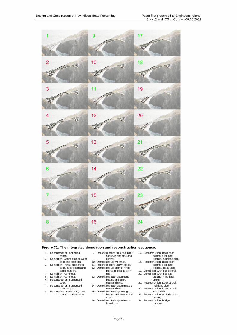
Figure 31: The integrated demolition and reconstruction sequence.
1. Reconstruction: Springing points.
2. Demolition: Connection between deck and arch ribs.
3. Demolition: Partial suspended deck, edge beams and some hangers.
4. Demolition: As note 3. 5. Demolition: As note 3. 6. Reconstruction: Suspended
deck. 7. Reconstruction: Suspended
deck hangers. 8. Reconstruction arch ribs, back-
spans, mainland side.
9. Reconstruction: Arch ribs, back-spans, island side and central.
10. Demolition: Crown brace. 11. Reconstruction: Crown brace. 12. Demolition: Creation of hinge
points in existing arch ribs.
13. Demolition: Back-span edge beams and deck, mainland side.
14. Demolition: Back-span trestles, mainland side.
15. Demolition: Back-span edge beams and deck island side.
16. Demolition: Back-span trestles island side.
17. Reconstruction: Back-span beams, deck and trestles, mainland side.
18. Reconstruction: Back-span beams, deck and trestles, island side.
19. Demolition: Arch ribs central. 20. Demolition: Arch ribs and
bracing in the back spans.
21. Reconstruction: Deck at arch mainland side.
22. Reconstruction: Deck at arch island side.
23. Reconstruction: Arch rib cross-bracing
24. Reconstruction: Bridge parapets.
Page 12