the design and thermo-structural analysis of target
TRANSCRIPT

Contents lists available at ScienceDirect
Nuclear Materials and Energy
journal homepage: www.elsevier.com/locate/nme
The design and thermo-structural analysis of target assembly for highintensity neutron source
E. Wakaia,⁎, K. Watanabeb, H. Kondoc, F. Groescheld
a Japan Atomic Energy Agency, Tokai-mura, 319-1195, Japanb Research Organization for Information Science and Technology, Kobe 650-0047 JapancNational Institutes for Quantum and Radiological Science and Technology, Naka 311-0193 Japand Karlsruhe Institute of Technology, 76131 Karlsruhe, Germany
A R T I C L E I N F O
Keywords:High intensity neutron sourceTarget assemblyThermo-structural analysisLi targetIFMIFF82H
A B S T R A C T
The engineering design of an integrated target assembly of IFMIF lithium target was performed in IFMIF/EVEDAproject for a high intensity neutron source. In the evaluation of the design, a thermos-structural analysis of wasevaluated by ABAQUS code, and the modeling region was a part of the target assembly which was from the inletnozzle to the outlet pipe. The material of the target assembly including the back plate was F82H steel. In thethermal-structural analysis, the normal operations and start/stop or abnormal operations were evaluated at 250or 300 °C operation of Li flow in inlet pipe. The result showed that the temperature of the target assembly wasevaluated to be still lower than the Li boiling point of 344 °C under a vacuum pressure of 10−3 Pa. In a tem-perature constant operation, the calculated stresses and displacements were small enough for thermal soundnessof the target assembly in steady states. In a transient cooling process from 300 °C to 20 °C through 250 °C, themaximum Mises stress was found to be 372MPa, which was lower than the yield stress at 300 °C.
1. Introduction
The main function of the International Fusion Materials IrradiationFacility (IFMIF) or the other neutron source facilities is to generate thehigh intense neutrons by injecting the deuteron or proton beams ac-celerated to high energy onto the target material such as liquid target ofLi [1-4], Hg [5–7] Pb-Bi [8,9] and solid target [9–12]. The highest beampower in them is 10 MW of the IFMIF. The engineering validation anddesign activities (EVEDA) for IFMIF were performed to start from 2007in a jointed program between the EU and Japan as a Broader Approach(BA) for fusion demo reactor. Some validation test and engineeringdesign for lithium target facility of IFMIF were completed [13–28].
The objective of IFMIF is to generate high intensity neutrons, whichare similar to fusion neutrons with 14 MeV, by injecting the deuteronbeams accelerated to high energy onto the 260mm wide and 25mmthick free-surface lithium flow. Guiding the liquid lithium along theconcave back plate at a speed of 15m/s is required to increase thepressure in the lithium flow by centrifugal force, to avoid boiling by theheat input of the deuteron beams, and to remove heat by the lithiumflow circulation [2,29]. This enables the target geometry to be main-tained at the time of heat input, which is unexpected for solid target,and realizes the steady-state neutron source. IFMIF is composed of
lithium target facility, accelerator facility, test facility with high fluxmodule [14,30] and the other modules, and conventional facility.
In IFMIF operation after EVEDA, intense neutrons are emitted insidethe Li flow through a thin back plate attached to the target assembly.Since the back plate is operating under a severe neutron irradiation of50 dpa/year and a maximum nuclear heating rate of 25W/cm3,thermo-structural design is one of critical issues in a target design. Theback plate is replaced in annual maintenance after every 11 monthsoperation because of neutron irradiation damage. Two design optionsof the target assembly for the back plate replacement are under in-vestigation. The first option is an “Integrated type” target assemblywhere the Li flow channel includes an integral back plate. This optionrequires replacement of the entire target assembly prior to life time of aportion of it. The second option is a target assembly with replaceablebayonet-type back plate. In this option, only the back plate will be re-placed [21,22]. The Guiding the lithium flow along the concave backplate in target assembly at a speed of 15m/s at 250 °C is required toincrease the pressure in the lithium flow by centrifugal force, to avoidboiling by the heat input 10 MW by the 40 MeV deuteron two beamswith 250mA in total, and to remove heat by the lithium flow circula-tion. In this study, the thermos-structural analysis and the design of anintegrated target assembly (TA) of IFMIF lithium target was evaluated.
https://doi.org/10.1016/j.nme.2018.07.005Received 15 December 2017; Received in revised form 27 June 2018; Accepted 11 July 2018
⁎ Corresponding author.E-mail address: [email protected] (E. Wakai).
Nuclear Materials and Energy 17 (2018) 15–23
2352-1791/ © 2018 The Authors. Published by Elsevier Ltd. This is an open access article under the CC BY-NC-ND license (http://creativecommons.org/licenses/BY-NC-ND/4.0/).
T

Some of engineering design of lithium target facility of IFMIF werepresented by some studies [2–4,13]. The main specification of lithiumtarget facility of IFMIF engineering design is shown in Table 1.
2. System diagram of target assembly of lithium target facility ofIFMIF
The system diagram of the lithium target facility was given in Fig. 1.The facility is composed of main lithium loop, lithium target system andtarget assembly, lithium flow measurement system and diagnostics,target test cell, beam duct, electro-magnetic pump system, impuritymonitoring loop, impurity control system (lithium purification loop),quench tank and drain tank system, heat removal system, and remotehandling systems.
In the main lithium loop and target assembly, the main Li loopcirculates liquid Li through the TA by the main electro-magnetic pump(EMP). The TA with the Li inlet pipe with an outer diameter of
165.2 mm (in JIS, 6B, Sch.40), a part of the Li outlet channel and partsof the beam ducts are in the TC. Temperature of the BP, thickness ofwhich is the thinnest among Li components and most severely irra-diated by neutron and gamma ray, is monitored. There is no vacuumport in TC. Beam duct vacuum pressure is maintained by vacuumpumps through vacuum ports both outside of TC. Downstream end ofthe Li outlet channel is below the Li level in the QT by 0.2m to suppressLi splash by confinement by duct and Li boiling by the head pressure.Also downstream end of the bypass is below the Li level to avoid ca-vitation under vacuum condition of QT with reflecting experiences atthe EVEDA Lithium Test Loop (ELTL) operation. Temperature and Lilevel of QT are monitored. A Li overflow line is near the top of QT.Height difference between the overflow and the reference Li level inoperation is about 0.2m corresponding to Li volume beyond the re-ference level. Vacuum of the QT is maintained at 10−3 Pa or lessthrough the surge tank (ST). Also Ar is supplied or evacuated throughthe ST. There is a gate valve under QT, which is closed at each TAreplacement to limit volume exposed atmosphere containing air (O andN). All valves for Li components are opened and closed remotely bypressurized Ar gas, since no worker is accessible to the areas in beamoperation when radiation is too high for workers and the areas are filledwith Ar gas. Outer diameter of pipes between the QT and the main EMPis 267.4 mm (10B, Sch.20S) for smaller pressure drop to avoid cavita-tion at the inlet of the EMP located at the lowest among operating Licomponents, 6.5 m below the Li level in QT. Branch lines to/from theImpurity Reduction System (IRS) are connected to this section. Pressurein this section is low in comparison with the other part of the main Liloop. This condition eases design pressure of the ICS. Li flow rate at theexit of the EMP is finely controlled by feedback with a flow rate mea-sured at the electro-magnetic flow meter (EMFM). Temperature of theEMP coil is monitored for a feedback control on a start of blower forcooling. Outer diameter of pipes downstream the EMP is 216.3 mm (8B,
Table 1Main specification of Li flowing target in IFMIF. Temperature will be in-creased to 350 °C inside lithium flow by the beam injection. The surfacetemperature will be elevated up to 280 °C. The margin of boiling temperatureat the surface is about 40 °C.
Item Condition
Heating power 10 MWVacuum 10−3 ∼ 10−2 PaLi temperature in inlet pipe 250 °CFlow velocity 15m/s (max. 16m/s)Li flowing thickness and width 0.025m, 0.26 mLi thickness variation ≦± 1 mmLi amount 9 m3 (4.5 tons)Li flow rate 130 l/s
Fig. 1. System diagram of lithium target facility of IFMIF. (FE: Flow element, FI: Flow indicator, FM: Flow meter, LE: Level element, LI: Level indicator, PE: Pressure element,PI: Pressure indicator, TC: Temperature controller, TE: Temperature element, TI: Temperature indicator, TIC: Temperature indicator controller, XT: Expansion tank).
E. Wakai et al. Nuclear Materials and Energy 17 (2018) 15–23
16

Sch.20S) in the LLA, but 165.2mm (6B, Sche.40) in the TC to reduceneutron and gamma ray through the wall penetration. Outer diameterof pipes of the bypass line is 114.3 mm (4B, Sch.20S), since the line isused for rather small flow rate up to 32.5 L/s (equivalent to 5m/s at theTA nozzle exit) in normal operation. The EMFM is calibrated withmonitoring Li level in the QT. For this purpose, the drain line waschanged to downstream of the EMFM. The primary heat exchanger(HX1) transfers the heat up 10 MW from liquid Li on the shell side toorganic oil ThermS-900® on the tube side. Even while a hotter fluid ison tube side in usual designs of heat exchangers, the liquid is in on theshell side in IFMIF LF design to reduce risk of tube plugging of Li whichfreezing point is 181 °C far higher than those of oils. In normal opera-tion, pressure of Li in the shell side of HX1 is 196–211 kPa (assuming
proportional to square of flow rate, i.e. (15/16)2 times) and pressure ofthe oil ThermS-900 is 166–180KPa. In case of tube rapture in HX1,leakage is in the direction from the Li to the oil. Pressure of Li at inletand outlet of the HX1 is monitored by pressure gauges with strain-gauges and membranes inside, whose type is the same as that fabricatedfor use at the ELTL. A remarkable change in absolute pressure orpressure difference between the two gauges tells malfunctions such astube/shell rupture or partial plugging, respectively. Temperature of Liat inlet and outlet of the HX1 is monitored. Temperature of Li in themain Li Loop is controlled by feedback with the Li temperature mea-sured at outlet of the HX1 typically. Li flow velocity in the shell side ofthe HX1 is very low, 0.2m/s at reference flow rate of 97.5 L/s. Note thatheaters and thermo-couples are equipped on not only the outlet of HX1
Fig. 2. Target assembly of lithium target facility.
Fig. 3. (a) CATIA CAD model, (b) and (c) ABAQUS mesh model of target assembly.
E. Wakai et al. Nuclear Materials and Energy 17 (2018) 15–23
17
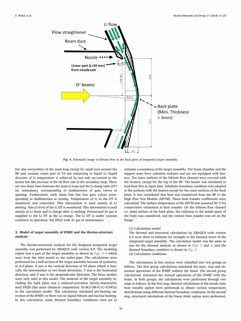
but also everywhere of the main loop except for small area around theBP and vacuum vessel part of TA not contacting to liquid Li. Rapiddecrease of Li temperature is achieved by not only no-current in theheater but also increase of the oil flow rate in the secondary loop. Thereare two drain lines between the main Li loop and the Li dump tank (DT)for redundancy corresponding to malfunctions of gate valves atopening. Furthermore, each drain line has two gate valves corre-sponding to malfunctions at closing. Temperature of Li in the DT ismonitored and controlled. This information is used mainly at Limelting. Also Li level of the Li DT is monitored. This information is usedmainly at Li drain and Li charge after Li melting. Pressurized Ar gas issupplied to the Li DT at the Li charge. The Li DT is under vacuumcondition in operation, but filled with Ar gas in maintenance.
3. Model of target assembly of IFMIF and the thermo-structureanalysis
The thermo-structural analysis for the designed integrated targetassembly was performed by ABAQUS code version 6.9. The modelingregion was a part of the target assembly as shown in Figs. 2–4 whichwere from the inlet nozzle to the outlet pipe. The calculations wereperformed for a half section of the target assembly because of symmetryto X-Z plane. X axis is the vertical direction of YZ plane which is basi-cally the intermediate of two beam directions, Y axis is the horizontaldirection, and Z axis is the perpendicular direction. The Hexa mesheswere only used in this model. The material of the target assembly in-cluding the back plate was a reduced-activation ferritic/martensiticsteel F82H (the main chemical composition: Fe-8Cr-2W-0.1C–0.04Ta)in the calculation model. This calculation simulated pre-heating op-eration of the IFMIF, so there was no liquid lithium and nuclear heating.In this calculation, some thermal boundary conditions were set to
estimate a soundness of the target assembly. The beam chamber and thesupport arms have radiation surfaces and are not equipped with hea-ters. The outer surfaces of the lithium flow channel were covered withthe heaters, except for the top of the BP. The heater was simulated toload heat flux as input data. Adiabatic boundary condition was adoptedto the surfaces with the heaters except for the outer surfaces of the backplate. It was considered that heat was transferred from the BP to theHigh Flux Test Module (HFTM). Those heat transfer coefficients werecalculated. The surface temperature of the HFTM was assumed 50 °C forconservative estimation at heat transfer. On the lithium flow channeli.e. inner surface of the back plate, the radiation to the inside space ofthe body was considered, and the contact heat transfer was set on theflange.
(1) Calculation modelThe thermal and structural calculations by ABAQUS code version6.9 were done to estimate for strength to the thermal stress of theintegrated target assembly. The calculation model was the same asone for the thermal analysis as shown in Figs. 3 and 4, and thethermal boundary condition is shown in Fig. 5.(2) Calculation conditions
The calculations in this section were classified into two groups asfollows. The first group calculations simulated the start, stop and ab-normal operations of the IFMIF without the beam. The second groupcalculations simulated the normal operations of the IFMIF with thebeam. In both groups, the calculations were performed through twosteps as follows. In the first step, thermal calculations of the steady stateheat transfer option were performed to obtain various temperaturedistributions using different thermal boundary conditions. In the secondstep, structural calculations of the linear static option were performed,
Fig. 4. Schematic image of lithium flow in the back plate of integrated target assembly.
E. Wakai et al. Nuclear Materials and Energy 17 (2018) 15–23
18

based on the temperature distributions obtained in the first step. Thecalculation cases of two groups are listed in Table 2. In thermal cal-culations of step 1, the boundary conditions were set. In this section,heater model was replaced by heat transfer from liquid Li. The thermalboundary conditions are listed in Table 3. In the structural calculationsof step 2, the constraint conditions for the displacement and rotationwere set. The calculated temperature of the lithium flow channel wasestimated higher than 200 °C. While in the other part of the target as-sembly, for example the flange, the body and the support, the calcu-lated temperature was estimated lower than 200 °C. Because themelting point of lithium is about 180 °C, the lithium flow channel shallbe preheated above 190 °C including a margin.
4. Calculation results of target assembly
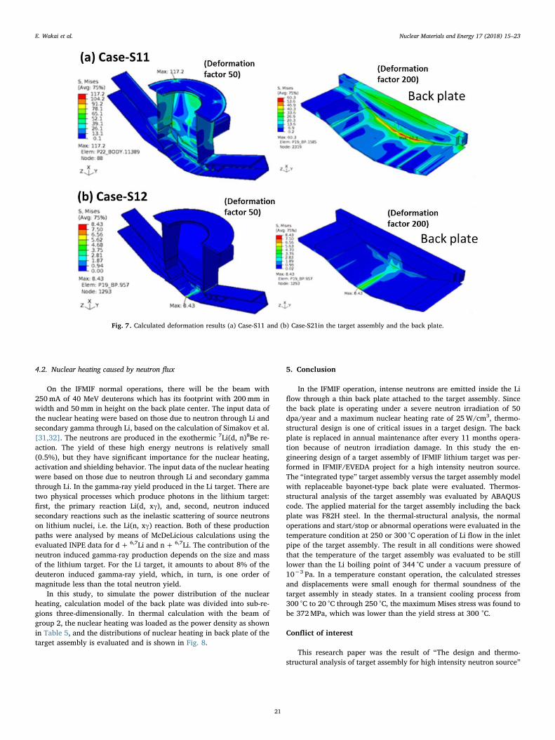
The calculation results are summarized in Tables 4 and 5. In Fig. 6,temperature distribution of target assembly (TA) with heater control.The calculated deformation results of Case-S11 and Case-S21in thetarget assembly and the back plate are shown in Fig. 7, where the de-formations are exaggerated by factors of 50 for the target assembly, 200for the back plate, respectively. This analysis was done to estimate in-tegrity of the integrated TA under the design pressure and the designtemperature before Li charge.
4.1. Transition process and normal keeping temperature condition
To compare the results in Case-S11 and in Case-S12, it was not areversible process for the temperature ascent and the temperaturedescent. (The temperature distribution was changed from uniform tonon-uniform in Case-S11, while it was changed from non-uniform to
Table 2List of calculation cases (*) a room temperature (No Li in flow channels).
Case ID Group Step Temperature ofboundary simulating Li( °C)
Heatingsimulatingnuclear heat
Case-T11 1. SimulatingIFMIF start/stop orabnormaloperations
(1) Thermal 300 OffCase-T12 250Case-T13 200Case-S11 (2) Structural 20*→250→300Case-S12 300→250→20*Case-S13 300→250→200→20*Case-T21 2. Simulating
IFMIFnormaloperations
(1) Thermal 300 OnCase-S21 (2) Structural 300 Off→OnCase-S22 300 On→Off
Table 3List of thermal boundary conditions.
Marks in Fig. 5 Models Locations Heat transfer coefficient (W/m2K) Emissivity (-) Boundary Temp. ( °C)
HT-1 Heat transfer BP / HFTM 43.4 – 50HT-2 BP / HFTM 11.0 – 50HT-3 Frame / HFTM 7.81 – 50HT-4 Frame / HFTM 6.72 – 50HT-5 Flange / Flange 15.8 – 50HT-6 Flow channel / Li 3.4E4 – 200∼300R-1 Radiation Outer (far from Li) – 0.3 50NBC No (Adiabatic) Outer (near to Li) – – –
Table 4Summary of calculated results (*) occurred in body.
Case ID Max. von Misesstress (MPa)
Magnitude Maximum displacement (mm)
in TA in BP X Y Z
Case-S11 117.2* 60.3 2.875 − 1.369 1.173 2.831Case-S12 371.9* 364.1 0.724 0.350 − 0.248 − 0.700Case-S13 281.9* 272.8 1.165 − 0.566 − 0.423 − 1.149Case-S21 8.43 8.43 3.14E−3 − 3.12E−3 1.92E−3 − 9.49E−4Case-S22 8.44 8.44 3.12E−3 3.12E−3 − 1.92E-3 9.49E−4
Fig. 5. Classification of the thermal boundary conditions in the outer surface, back plate surface, and flow channel and flange.
E. Wakai et al. Nuclear Materials and Energy 17 (2018) 15–23
19

uniform in Case-S12.) The maximum value of von Mises stress in Case-S12 was more than three times as large as that in Case-S11. The max-imum displacement was observed in Case-S11, and it was to be2.875mm in the instantaneous elevated temperature process from RTto 250 °C in the operation preparation process under a condition of nonuclear heating and no lithium flowing, and the magnitude of de-formation can be reduced by the decrease of the elevating temperaturerate.
In Case-S13, to add a step of 200 °C into the temperature descentprocess, the maximum stress was equal to 3/4 in Case-S12. The calcu-lated maximum von Mises stress, 282MPa was lower than the per-missible stress of F82H, 423MPa which was defined by the yield stressat 300 °C. The maximum Mises stress was found to be 372MPa intransient cooling process from 300 °C. In actual phenomenon, it is ex-pected that the temperature changing progress more slowly, so thethermal stress will be reduced furthermore. Therefore a soundness of
the target assembly could be estimated. To compare the results in Case-S21 and in Case-S22, it was a reversible process for the beam on and thebeam off. In both cases, the maximum von Mises stresses and magni-tude displacements were nearly same each other, and the maximumdisplacements in each direction had the same values and reverse di-rections each other. In those cases to change thermal conditions of thebeam on and off, the calculated stresses and displacements were smallenough, so it was considered that there was no problem for thermalsoundness of the target assembly. In this case, it was possible to esti-mate the temperature range of the lithium flow channel, 200 °C to325 °C by adjusting the input data of the heat flux of the heaters. Themaximum temperature of the TA is 325 °C, and it is still lower than theLi boiling point of 344 °C under a vacuum pressure of 10−3 Pa. The TAtemperature was reduced and became uniform, almost equaled to Litemperature (250 °C typically) after starting of Li circulation throughthe TA with heater control at the same time.
Table 5Power density in each region (W/mm3).
X-div. Y-div. Z-div.
A B C D E F G
Layer 3 6 2.242e−3 2.057e−3 1.909e−3 1.597e−3 1.189e−3 8.887e−4 5.549e−45 3.826e−3 3.460e−3 3.116e−3 2.629e−3 1.987e−3 1.383e−3 6.694e−44 1.724e−3 7.919e−43 1.964e−3 8.881e−42 2.228e−3 1.002e−31 2.365e−3 1.047e−3
Layer 2 6 2.516e-3 2.254e-3 2.070e−3 1.686e−3 1.199e−3 8.314e−4 5.155e−45 4.424e-3 3.956e-3 3.628e−3 2.798e−3 1.924e−3 1.099e−3 6.221e−44 2.448e−3 1.301e−3 7.224e−43 2.895e−3 1.520e−3 8.416e−42 3.374e−3 1.704e−3 9.314e−41 3.636e−3 1.868e−3 1.021e−3
Layer 1 6 2.516e−3 2.254e−3 2.070e−3 1.686e−3 1.199e−3 8.314e−4 5.155e−45 4.981e−3 4.299e−3 3.670e−3 2.568e−3 1.592e−3 1.043e−3 6.221e−44 1.023e−2 7.667e−3 5.634e−3 3.546e−3 2.016e−3 1.219e−3 7.224e−43 2.247e−2 1.494e−2 8.608e−3 4.516e−3 2.472e−3 1.440e−3 8.416e−42 2.488e−2 1.661e−2 1.003e−2 5.273e−3 2.832e−3 1.660e−3 9.314e−41 2.599e−2 1.754e−2 1.089e−2 5.852e−3 3.158e−3 1.843e−3 1.021e−3
Fig. 6. Temperature distribution of target assembly (TA) (before Li charge).
E. Wakai et al. Nuclear Materials and Energy 17 (2018) 15–23
20
4.2. Nuclear heating caused by neutron flux
On the IFMIF normal operations, there will be the beam with250mA of 40 MeV deuterons which has its footprint with 200mm inwidth and 50mm in height on the back plate center. The input data ofthe nuclear heating were based on those due to neutron through Li andsecondary gamma through Li, based on the calculation of Simakov et al.[31,32]. The neutrons are produced in the exothermic 7Li(d, n)8Be re-action. The yield of these high energy neutrons is relatively small(0.5%), but they have significant importance for the nuclear heating,activation and shielding behavior. The input data of the nuclear heatingwere based on those due to neutron through Li and secondary gammathrough Li. In the gamma-ray yield produced in the Li target. There aretwo physical processes which produce photons in the lithium target:first, the primary reaction Li(d, xγ), and, second, neutron inducedsecondary reactions such as the inelastic scattering of source neutronson lithium nuclei, i.e. the Li(n, xγ) reaction. Both of these productionpaths were analysed by means of McDeLicious calculations using theevaluated INPE data for d+ 6,7Li and n+ 6,7Li. The contribution of theneutron induced gamma-ray production depends on the size and massof the lithium target. For the Li target, it amounts to about 8% of thedeuteron induced gamma-ray yield, which, in turn, is one order ofmagnitude less than the total neutron yield.
In this study, to simulate the power distribution of the nuclearheating, calculation model of the back plate was divided into sub-re-gions three-dimensionally. In thermal calculation with the beam ofgroup 2, the nuclear heating was loaded as the power density as shownin Table 5, and the distributions of nuclear heating in back plate of thetarget assembly is evaluated and is shown in Fig. 8.
5. Conclusion
In the IFMIF operation, intense neutrons are emitted inside the Liflow through a thin back plate attached to the target assembly. Sincethe back plate is operating under a severe neutron irradiation of 50dpa/year and a maximum nuclear heating rate of 25W/cm3, thermo-structural design is one of critical issues in a target design. The backplate is replaced in annual maintenance after every 11 months opera-tion because of neutron irradiation damage. In this study the en-gineering design of a target assembly of IFMIF lithium target was per-formed in IFMIF/EVEDA project for a high intensity neutron source.The “integrated type” target assembly versus the target assembly modelwith replaceable bayonet-type back plate were evaluated. Thermos-structural analysis of the target assembly was evaluated by ABAQUScode. The applied material for the target assembly including the backplate was F82H steel. In the thermal-structural analysis, the normaloperations and start/stop or abnormal operations were evaluated in thetemperature condition at 250 or 300 °C operation of Li flow in the inletpipe of the target assembly. The result in all conditions were showedthat the temperature of the target assembly was evaluated to be stilllower than the Li boiling point of 344 °C under a vacuum pressure of10−3 Pa. In a temperature constant operation, the calculated stressesand displacements were small enough for thermal soundness of thetarget assembly in steady states. In a transient cooling process from300 °C to 20 °C through 250 °C, the maximum Mises stress was found tobe 372MPa, which was lower than the yield stress at 300 °C.
Conflict of interest
This research paper was the result of “The design and thermo-structural analysis of target assembly for high intensity neutron source”
Fig. 7. Calculated deformation results (a) Case-S11 and (b) Case-S21in the target assembly and the back plate.
E. Wakai et al. Nuclear Materials and Energy 17 (2018) 15–23
21

entrusted to Japan Atomic Energy Agency performed under IFMIF/EVEDA project.
Acknowledgments
The activity was performed under the IFMIF/EVEDA project. Theauthors are grateful to the members of IFMIF/EVEDA EU and JAmembers, fusion for energy and related ones. Especially, we would liketo express appreciation to Dr. R. Heidinger of F4E, Drs. G. Micciche, D.Bernardi, and S. Nitti of ENEA, Drs. F. Arbeiter, K. Tian, V. Heinzel, andA. Moselang, A. Ibarra of CIEMAT in EU team, and Drs. M. Ida, K.Nakamura, S. Niitsuma, H. Nakamura, K. Fujishiro, T. Kanemura, T.Nishitani, M. Sugimoto, H. Kimura, S. Ohira, Profs. E. Hoashi, S.Yoshihashi-Suzuki, H. Horiike, Y. Tsuji, T. Terai, S. Fukada, J. Yagi, A.Suzuki,and Ms. M. Hirano of JA team, and Drs. P. Garin, H. Matsumoto,J. Knaster, K. Fujishiro, and M. Perez of IFMIF/EVEDA project team,Profs. T. Muroga, T. Yokomine, and A. Kohyama for their fruitful dis-cussion and coordination.
References
[1] E. Wakai, T. Kanemura, H. Kondo, Y. Hirakawa, Y. Ito, H. Serizawa, Y. Kawahito,T. Higashi, A. Suzuki, S. Fukada, K. Furuya, K. Esaki, J. Yagi, Y. Tsuji, T. Ito,S. Niitsuma, S. Yoshihashi-Suzuki, K. Watanabe, T. Furukawa, F. Groeschel,G. Micciche, S. Manorri, P. Favuzza, F.S. Nitti, R. Heidinger, T. Terai, H. Horiike,M. Sugimoto, S. Ohira, J. Knaster, Engineering validation for lithium target facilityof the IFMIF under IFMIF/EVEDA project, Nuclear Mater. Energy 9 (2016)278–285.
[2] E. Wakai, H. Kondo, T. Kanemura, T. Furukawa, Y. Hirakawa, K. Watanabe, M. Ida,Y. Ito, S. Niitsma, Y. Edao, K. Fujishiro, K. Nakaniwa, E. Hoashi, H. Horiike,
H. Serizawa, Y. Kawahito, S. Fukada, Y. Sugie, A. Susuki, J. Yagi, Y. Tsuji,K. Furuya, F. Groeschel, J. Knaster, G. Micchiche, A. Ibarra, R. Heidinger, F. Nitti,M. Sugimoto, Engineering validation and engineering design of lithium target fa-cility in IFMIF/EVEDA project, Fus. Sci. Technol. 66 (2014) 46–56.
[3] E. Wakai, H. Kondo, M. Sugimoto, S. Fukada, J. Yagi, M. Ida, T. Kanemura,T. Furukawa, Y. Hirakawa, K. Fujishiro, A. Suzuki, T. Terai, Y. Edao, T. Hiromoto,S. Shigeharu, S. Niitsuma, H. Kimura, H. Horiike, E. Hoashi, S. Suzuki, N. Yamaoka,H. Serizawa, Y. Kawahito, Y. Tsuji, K. Furuya, F. Takeo, Development of LithiumTarget System in Engineering Validation and Engineering Design Activity of theInternational Fusion Materials Irradiation Facility (IFMIF/EVEDA), J. Plasma Fus.Res. 88 (2012) 691–705.
[4] J. Knaster, P. Garin, H. Matsumoto, Y. Okumura, M. Sugimoto, F. Arbeiter, P. Cara,S. Chel, A. Facco, P. Favuzza, T. Furukawa, R. Heidinger, A. Ibarra, T. Kanemura,A. Kasugai, H. Kondo, V. Massaut, J. Molla, G. Micciche, S. O'hira, K. Sakamoto,T. Yokomine, E. WakaiIFMIF/EVEDA Integrated Project Team, Overview of theIFMIF/EVEDA project, Nucl. Fus. 57 (2017) 102016(25pp).
[5] L. Mansur, Materials research and development for the spallation neutron sourcemercury target, J. Nucl. Mater 318 (2003) 14–25.
[6] H. Takada, K. Haga, M. Teshigawara, T. Aso, S. Meigo, H. Kogawa, T. Naoe,T. Wakui, M. Ooi, M. Harada, M. Futakawa, Materials and Life ScienceExperimental Facility at the Japan Proton Accelerator Research Complex I: PulsedSpallation Neutron Source, Quantum Beam Sci. 1 (2017) 2017, 8-pp.1–26.
[7] J.R. Haines, T.J. McManamy, T.A. Gabriel, R.E. Battle, K.K. Chipley, J.A. Crabtree,L.L. Jacobs, D.C. Lousteau, M.J. Rennich, B.W. Riemer, Spallation neu-tronsourcetargetstationdesign, development, and commissioning, Nuclear Instrum.Methods Phys. Res. A 764 (2014) 94–115.
[8] Y. Dai, G.S. Bauer, Status of the first SINQ irradiation experiment, STIP-I, J. Nucl.Mater 296 (2001) 43–53.
[9] L.K. Mansur, J.R. Haines, Status of the Spallation Neutron Source with focus ontarget materials, J. Nucl. Mater 356 (2006) 1–15.
[10] T. McManamy, M. Rennich, F. Gallmeier, P. Ferguson, J. Janney, 3MW solid ro-tating target design, J. Nucl. Mater 398 (2010) 35–42.
[11] A.R. Paramo, F. Sordo, J.M. Perlado, A. Rivera, Viability of the ESS-Bilbao neutronsource for irradiation of nuclear fusion materials, J. Nucl. Mater 444 (2014)469–474.
[12] X.J. Jia, G.S. Bauer, W. He, Y.L. Sun, T.J. Liang, W. Yin, D. Zha, Mock-up stands for
Fig. 8. Distributions of nuclear heating in back plate of the Li target assembly. X axis is the vertical direction of YZ plane which is basically the intermediate of twobeam directions, Y axis is the horizontal direction, and Z axis is the perpendicular direction.
E. Wakai et al. Nuclear Materials and Energy 17 (2018) 15–23
22

a rotating target for CSNS project, J. Nucl. Mater 398 (2010) 28–34.[13] F.S. Nitti, A. Ibarra, M. Ida, P. Favuzza, T. Furukawa, F. Groeschel, R. Heidinger,
T. Kanemura, J. Knaster, H. Kondo, G. Micchiche, M. Sugimoto, E. Wakai, Thedesign status of the liquid lithium target facility of IFMIF at theend of the en-gineering design activities, Fus. Eng. Des 100 (2015) 425–430.
[14] F. Arbeiter, N. Baluc, P. Favuzza, F. Groeschel, R. Heidinger, A. Ibarra, J. Knater,T. Kanemura, H. Kondo, V. Massaut, F.S. Nitti, G. Micchiche, S. O'hira,D. Rapisarda, M. Sugimoto, E. Wakai, T. Yokomine, The accomplishments of lithiumtarget and test facility validation activities in the IFMIF/EVEDA phase, Nucl. Fus. 58(6pp) (2018) 015001.
[15] H. Kondo, T. Kanemura, T. Furukawam Y. Hirakawa, E. Wakai, Cavitation inceptionupstream of liquid lithium target for intense fusion neutron source, Fus. Eng. Des.124 (2017) 990–994.
[16] T. Kanemura, H. Kondo, T. Furukawa, Y. Hirakawa, E. Hoashi, S. Yoshihashi,H. Horiike, E. Wakai, Measurement of Surface Velocity of Li Target in IFMIF/EVEDA Li Test Loop, Fus. Eng. Des. 109-111 (2016) 1682–1686.
[17] H. Kondo, T. Kanemura, T. Furukawa, Y. Hirakawa, E. Wakai, J. Knaster,Experimental Study on Cavitation of a Liquid Lithium Jet for International FusionMaterials Irradiation Facility, J. Nuclear Eng. Radiat. Sci. 3 (2017) 041005-1 –041005-11.
[18] H. Kondo, T. Kanemura, T. Furukawa, Y. Hirakawa, E. Wakai, J. Knaster, Validationof liquid lithium target stability for an intense neutron source, Nucl. Fus. 57 (2017)066008.
[19] P. Favuzza, A. Antonelli, T. Furukawa, F. Groeschel, R. Heidinger, T. Higashi,Y. Hirakawa, M. Iijima, Y. Ito, T. Kanemura, J. Knaster, H. Kondo, G. Micciche,F.S. Nitti, S. Ohira, M. Severi, M. Sugimoto, A. Suzuki, R. Traversi, E. Wakai, Roundrobin test for the determination of nitrogen concentration in solid lithium, Fus. Eng.Des. 107 (2016) 13–24.
[20] E. Wakai, et al., Nitrogen hot trap design and manufactures for lithium test loop inIFMIF/EVEDA project, Plasma Fusion and Res. 11 (2016) 2405112-1 to 4.
[21] H. Nakamura, P. Agostini, K. Ara, S. Fukada, K. Furuya, P. Garin, et al., Latestdesign of liquid lithium target in IFMIF, Fus. Eng. Des. 84 (2009) 252–258.
[22] K. Watanabe, M. Ida, H. Kondo, N. Nakamura, E. Wakai, Thermo-structural analysis
of integrated back plate in IFMIF/EVEDA liquid lithium target, Fus. Eng. Des. 86(2011) 2482–2486.
[23] J. Knaster, F. Arbeiter, P. Cara, S. Chel, A. Facco, R. Heidinger, A. Ibarra,A. Kasugai, H. Kondo, G. Micciche, K. Ochiai, S. O'hira, Y. Okumura, K. Sakamoto,E. Wakai, IFMIF, the European–Japanese efforts under the Broader Approachagreement towards a Li(d,xn) neutron source: Current status and future options,Nuclear Mater. Energy 9 (2016) 46–54.
[24] M. Ida, H. Kondo, K. Nakamura, E. Wakai, Hydraulic analysis on effects of back-plate deformation upon stability of high-speed free-surface lithium flow for IFMIFtarget design, Fus. Eng. Des. 86 (2011) 2478–2481.
[25] K. Esaki, K. Hiyane, S. Fukada, E. Wakai, Y. Ito, F. Nitti, Study on control of non-metallic impurities in liquid lithium, J. Plasma Fus. Res. SERIES 11 (2015) 36–40.
[26] S. Yoshihashi-Suzuki, E. Hoashi, T. Kanemura, H. Kondo, N. Yamaoka, H. Hiriike,Characteristics of surface oscillation on high speed liquid Li jet, Fus. Eng. Des. 87,2012, 1434–1438.
[27] E. Hoashi, S. Yoshihashi-Suzuki, H. Nanba, T. Kanemura, H. Kondo, T. Furukawa,N. Yamaoka, H. Horiike, Numerical study on free surface flow of liquid metal li-thium for IFMIF, Fus. Eng. Des. 88 (2013) 2515–2519.
[28] J. Yagi, A. Suzuki, T. Terai, Nitrogen contamination effect on yttrium gettering ofhydrogen in liquid lithium, J. Nucl. Mater 417 (2011) 710–712.
[29] M. Ida, H. Nakamura, H. Nakamura, H. Nakamura, K. Ezato, H. Takeuchi, Thermal-hydraulic characteristics of IFMIF liquid lithium target, Fus. Eng. Des. 63–64 (2002)333.
[30] T. Yokomine, T. Yoshida, T. Kunugi, E. Wakai, Neutronic Analysis of IFMIF HighFlux Test Module for High Temperature Irradiation, Fus. Sci. Technol. 68 (2015)657–661.
[31] S.P. Simakov, U. Fischer, U. von Moellendorff, I. Schmuck, A. Konobeev,P. Pereslavtsev, Advanced Monte Carlo procedure for the IFMIF d-Li neutron sourceterm based on evaluated cross section data, J. Nucl. Mater 307–311 (2002)1710–1714.
[32] S.P. Simakov, U. Fischer, K. Kondo, P. Pereslavtsev, Status of the McDeLiciousApproach for the D-Li Neutron Source Term Modeling in IFMIF NeutronicsCalculations, Fus. Sci. Technol. 62 (2012) 233–239.
E. Wakai et al. Nuclear Materials and Energy 17 (2018) 15–23
23