the design of an energy-efficient ir-uwb transmitter with
TRANSCRIPT
IEEE TRANSACTIONS ON CIRCUITS AND SYSTEMS—II: EXPRESS BRIEFS, VOL. 65, NO. 10, OCTOBER 2018 1485
The Design of an Energy-Efficient IR-UWBTransmitter With Wide-Output Swing and
Sub-Microwatt Leakage CurrentZhe Zhang , Yongfu Li , Senior Member, IEEE, Guoxing Wang , Senior Member, IEEE,
and Yong Lian, Fellow, IEEE
Abstract—In this brief, we present an impulse-radio ultra-wideband (IR-UWB) transmitter for low-power communicationand radar sensing applications. To improve the leakage powerfor the IR-UWB transmitter, we have adopted transistor stack-ing technique in the design of our digitally controlled oscillator(DCO) and mask generator. The DCO and mask generator cir-cuit generate the UWB carrier frequency and pulse mask signals,respectively. These signals are combined through a cascode out-put driver stage with an on-chip inductor load. The cascodestructure significantly reduces the leakage power. The on-chipinductor load improves the transmitted pulse amplitude. As aresult, our proposed transmitter has significantly reduced theleakage power to sub-micro watt and achieved a maximum ampli-tude of 0.94 V. Therefore, we are able to achieve a maximumefficiency of 8.6% and the transmitted energy per pulse is 3.6-pJ.
Index Terms—Impulse-radio ultra-wideband (IR-UWB), all-digital IR-UWB transmitter, digitally-controlled oscillator (DCO).
I. INTRODUCTION
IMPULSE-RADIO ultra-wideband (IR-UWB) technologyhas been widely studied for low power biomedical wire-
less applications [1]. It can be used in short-range wirelessdata communication systems in the wireless body area network(WBAN), or in radar sensors which remotely detect vital signssuch as heartbeat and respiration. An IR-UWB transmitter-receiver was proposed in our previous work to reconfigure thesame IR-UWB front-end for both communication and radarmodes [2]. IR-UWB transceivers show its unique advantagein integrating with the emerging asynchronous analog sensingplatform [3], [4]. In this brief, we proposed an energy effi-cient IR-UWB transmitter with low leakage current and hightransmission efficiency.
In an IR-UWB transmitter, IR-UWB pulses can be gen-erated in the same way as in narrow-band transmitter by
Manuscript received June 14, 2018; accepted July 18, 2018. Date of publica-tion July 31, 2018; date of current version September 27, 2018. This work wassupported in part by the National Key Research and Development Programof China under Grant 2016YFE0116900 and in part by the Natural ScienceFoundation of China under Grant 61474074. This brief was recommended byAssociate Editor C.-C. Chu. (Corresponding author: Yongfu Li.)
Z. Zhang is with Huawei International Pte Ltd., Singapore 117674 (e-mail:[email protected]).
Y. Li, G. Wang, and Y. Lian are with the School of Microelectronics,Shanghai Jiao Tong University, Shanghai 200240, China (e-mail: [email protected]).
Color versions of one or more of the figures in this paper are availableonline at http://ieeexplore.ieee.org.
Digital Object Identifier 10.1109/TCSII.2018.2861833
multiplying the baseband signal with a Local Oscillator (LO)signal [5]. This circuit implementation is not suitable for low-power biomedical application. Alternatively, pulsed oscillatormethod was proposed where the IR-UWB pulse is generatedwhen the oscillator is started and stopped by the basebandpulse [6]–[8]. However, the response time of the oscilla-tor limits the transmitter output bandwidth. In this brief, weproposed a new IR-UWB transmitter to overcome the existinglimitations while achieving state-of-the-art performance.
In the design of an IR-UWB transmitter for biomedicalapplications, it is important to achieve low leakage powerand high transmission energy efficiency simultaneously. Theleakage power must be minimized to prolong the lifespan ofthe portable sensor. In our previous work, we have demon-strated that the use of asynchronous sensing with an IR-UWBtransmitter can reduce the data rate of digitalized ECG sig-nals to 2 kbps [3]. Under this low data rate, the dynamicpower of the IR-UWB transmitter is comparable with theleakage power. To improve the transmission energy efficiencyand distance, the transmitted pulse energy and output volt-age amplitude should be large. This requires large transmitteroutput driver transistors in which the leakage power becomessignificant. Therefore, it is challenging to achieve high trans-mission energy efficiency and low leakage power for IR-UWBtransmitter at the same time.
In this design, we have reduced the leakage power of ourIR-UWB transmitter by adopting transistor stacking techniquein the design of the digitally-controlled oscillator (DCO) andmask generator. The DCO and mask generator circuits gen-erate the UWB carrier frequency and pulse mask signals,respectively. The combination of the UWB carrier frequencyand pulse mask signals produce an IR-UWB pulse, which isachieved through the use of a cascode output driver stagewith an on-chip inductor load. Since the transistor sizes ofthe output driver are big to drive the antenna impedance,cascode output driver structure significantly reduces the leak-age power. The on-chip inductor load improves the trans-mitted pulse amplitude. Therefore, we are able to achievesub-microwatt leakage power and increase transmitted pulseamplitude.
This brief is organized as follows. Section II introducesthe transmitter architecture and circuitry. Section III presentsthe measurement results and comparison with other works.Conclusion is given in Section IV.
1549-7747 c© 2018 IEEE. Personal use is permitted, but republication/redistribution requires IEEE permission.See http://www.ieee.org/publications_standards/publications/rights/index.html for more information.
1486 IEEE TRANSACTIONS ON CIRCUITS AND SYSTEMS—II: EXPRESS BRIEFS, VOL. 65, NO. 10, OCTOBER 2018
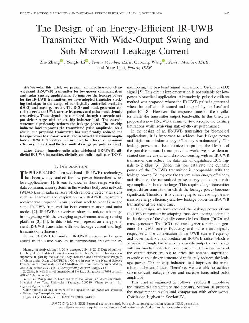
Fig. 1. Architecture of the IR-UWB Transmitter.
Fig. 2. Schematic of the one-shot circuit.
II. TRANSMITTER ARCHITECTURE AND CIRCUIT DESIGN
A. Transmitter Architecture
The system architecture of the transmitter is presented inFig. 1. First, the rising edge of the incoming data is usedto generate a narrow pulse by the one-shot circuit (Fig. 2).This narrow pulse is used to turn on and off the DCO andmask generator. Thus, this method helps to reduce the leakagecurrent when no data is transmitted. A twelve-bit coarse-finefrequency tuning is implemented in the DCO to control thecenter frequency of the UWB pulse. An eight-bit mask gener-ator circuit is implemented to control the shape of the IR-UWBpulse. Both the frequency signal and the pulse shaping signalare used to drive the cascode amplifier with an inductive load.The on-chip inductor resonates with the output capacitanceand increases the output voltage swing.
B. One-Shot Circuit
As shown in Fig. 2, the schematic of our one-shot circuitconsists of a NAND gate and an inverter. In this brief, wehave designed our IR-UWB signal maximum bandwidth tobe 400-MHz, which corresponds to a pulse width of 2.5-ns.Therefore, the delay of the pulse should be larger than 3-ns.
C. Digital-Controlled Oscillator
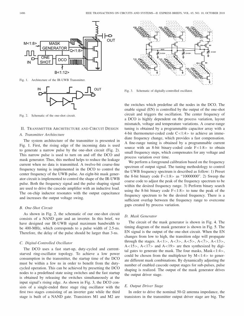
The DCO uses a fast start-up, duty-cycled and current-starved ring-oscillator topology. To achieve a low powerconsumption in the transmitter, the startup time of the DCOmust be within a few ns in order to benefit from the duty-cycled operation. This can be achieved by presetting the DCOnodes to a predefined state using switches and the fast startupis obtained by releasing the switches simultaneously at theinput signal’s rising edge. As shown in Fig. 3, the DCO con-sists of a single-ended three stage ring oscillator with thefirst two stages consisting of an inverter gate while the thirdstage is built of a NAND gate. Transistors M1 and M2 are
Fig. 3. Schematic of digitally-controlled oscillator.
the switches which predefine all the nodes in the DCO. Theenable signal (EN) is controlled by the output of the one-shotcircuit and triggers the oscillation. The center frequency ofa DCO is highly dependent on the process variation, layoutmismatch, voltage and temperature variations. A coarse-rangetuning is obtained by a programmable capacitor array with a4-bit thermometer-coded code C<1:4> to achieve an imme-diate frequency change, which provides a fast compensation.A fine-range tuning is obtained by a programmable currentsource with an 8-bit binary-coded code F<1:8> to obtainsmall frequency steps, which compensates for any voltage andprocess variation over time.
We perform a foreground calibration based on the frequencyspectrum of output signal. The tuning methodology to controlthe UWB frequency spectrum is described as follow: 1) Presetthe 8-bit binary code F<1:8> as “10000000”. 2) Sweep thecoarse code to adjust the peak of the frequency spectrum to bewithin the desired frequency range. 3) Perform binary searchusing the 8-bit binary code F<1:8> to tune the peak of thefrequency spectrum to be the desired frequency. There is asufficient overlap between the frequency range to overcomegaps created by process variation.
D. Mask Generator
The circuit of the mask generator is shown in Fig. 4. Thetiming diagram of the mask generator is shown in Fig. 5. TheEN signal is the output of the one-shot circuit. When the ENchanges from low to high, the transition edge will propagatethrough the stages. A<1>, A<3>, A<5>, A<7>, A<13>,A<15>, A<17> and A<19> are then synthesized by digi-tal gates to generate the mask. The four masks, Mask<1:4>,could be chosen from the multiplexer by M<1:4> to gener-ate different mask combinations. By dynamically adjusting thenumber of enabled cascode output stages for sub-pulses, pulseshaping is realized. The output of the mask generator drivesthe output driver stage.
E. Output Driver Stage
In order to drive the nominal 50-� antenna impedance, thetransistors in the transmitter output driver stage are big. The
ZHANG et al.: DESIGN OF ENERGY-EFFICIENT IR-UWB TRANSMITTER WITH WIDE-OUTPUT SWING AND SUB-MICROWATT LEAKAGE CURRENT 1487
Fig. 4. Schematic of TSPC mask generator.
Fig. 5. Schematic of mask generator.
Fig. 6. Schematic of the cascode output driver stage.
leakage power of the output stage is dominant in the wholetransmitter. Simple inverter can be used as the driver stage ofthe IR-UWB transmitter. However, the leakage power of thesimple inverter increases significantly as the sizes the transis-tors get larger. In this design, the output driver is composed ofparallel digital cascode stages which also combine the DCOoutput with the mask signal. When no pulse is transmitted,
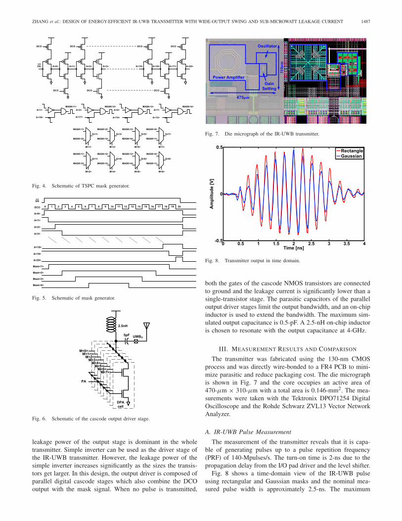
Fig. 7. Die micrograph of the IR-UWB transmitter.
Fig. 8. Transmitter output in time domain.
both the gates of the cascode NMOS transistors are connectedto ground and the leakage current is significantly lower than asingle-transistor stage. The parasitic capacitors of the paralleloutput driver stages limit the output bandwidth, and an on-chipinductor is used to extend the bandwidth. The maximum sim-ulated output capacitance is 0.5-pF. A 2.5-nH on-chip inductoris chosen to resonate with the output capacitance at 4-GHz.
III. MEASUREMENT RESULTS AND COMPARISON
The transmitter was fabricated using the 130-nm CMOSprocess and was directly wire-bonded to a FR4 PCB to mini-mize parasitic and reduce packaging cost. The die micrographis shown in Fig. 7 and the core occupies an active area of470-μm × 310-μm with a total area is 0.146-mm2. The mea-surements were taken with the Tektronix DPO71254 DigitalOscilloscope and the Rohde Schwarz ZVL13 Vector NetworkAnalyzer.
A. IR-UWB Pulse Measurement
The measurement of the transmitter reveals that it is capa-ble of generating pulses up to a pulse repetition frequency(PRF) of 140-Mpulses/s. The turn-on time is 2-ns due to thepropagation delay from the I/O pad driver and the level shifter.
Fig. 8 shows a time-domain view of the IR-UWB pulseusing rectangular and Gaussian masks and the nominal mea-sured pulse width is approximately 2.5-ns. The maximum

1488 IEEE TRANSACTIONS ON CIRCUITS AND SYSTEMS—II: EXPRESS BRIEFS, VOL. 65, NO. 10, OCTOBER 2018
Fig. 9. Transmitter output in the frequency domain and its compliance withthe FCC mask.
Fig. 10. Transmitter output in the frequency domain for various supplyvoltages.
output voltage swing is 940-mV, as shown in Fig. 8. Witha PRF of 10-Mpulses/s, the resulting spectrum of the outputpulse achieves both indoor and outdoor FCC compliance withmore than 24 dB of sidelobe suppression without requiringthe use of an off-chip filter, as shown in Fig. 9. The powerspectrum density (PSD) −10 dB bandwidth is about 480-MHzand the PSD is below −42.15 dBm/MHz. The measured spec-trum also achieves FCC compliance within the supply voltagerange from 1.1 to 1.3-V, as shown in Fig. 10.
B. Power Measurement
The power consumption of the transmitter was analyzed forvarious PRFs from 100-pulses/s to 140-Mpulses/s, as shownin Fig. 11 (a). The average leakage power, PL = 725.9-nW.The PRF dependent part is 36.9 ± 4.4 − μW/PRF(Mpulse/s).As can be seen in Fig. 11 (b), the overall energy (activeand leakage) per pulse, EdTX ranges from 7.6-nJ/pulse at aPRF of 100-pulse/s to 37.9 ± 4-pJ/pulse with PRF beyond200-kpulse/s. The average deviation of ±4-pJ/pulse arisesfrom different masking modes. The transmitted pulse energyis EpTX = 3.6-pJ/pulse, based on calculation from the time-domain output waveform. Thus, the transmitter achieves amaximum efficiency η = 8.6%.
Fig. 11. (a) Power consumption of the transmitter versus the PRF, (b) Energyper pulse of the transmitter versus the PRF.
Fig. 12. Center frequency of the transmitter output versus different tuningcodes.
C. Frequency Tuning Measurement
The measured center frequencies of the transmitter outputversus different coarse and fine tuning codes are shown inFig. 12. The coarse tuning codes of C<1:4> = “0000” meetthe UWB frequency spectrum requirement. One of the mea-surement observations is that the fine tuning is nonlinear andonly a few MSBs of F<1:8> are effective. In UWB appli-cations there is no requirement for linear fine tuning of thecenter frequency.
ZHANG et al.: DESIGN OF ENERGY-EFFICIENT IR-UWB TRANSMITTER WITH WIDE-OUTPUT SWING AND SUB-MICROWATT LEAKAGE CURRENT 1489
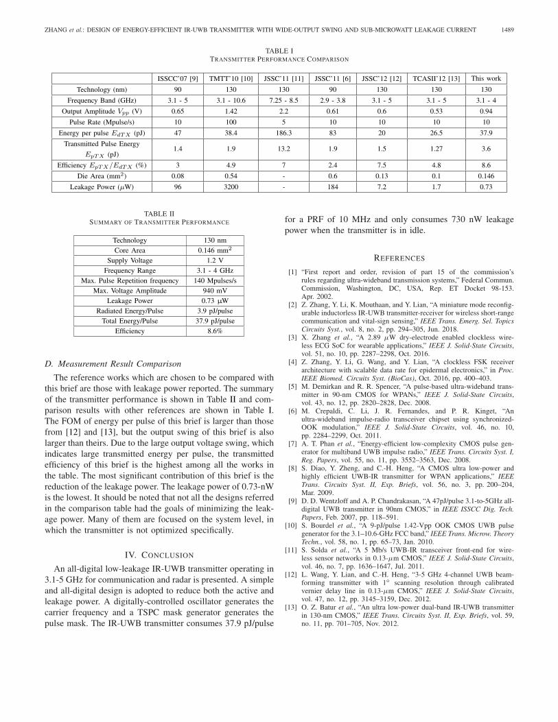
TABLE ITRANSMITTER PERFORMANCE COMPARISON
TABLE IISUMMARY OF TRANSMITTER PERFORMANCE
D. Measurement Result Comparison
The reference works which are chosen to be compared withthis brief are those with leakage power reported. The summaryof the transmitter performance is shown in Table II and com-parison results with other references are shown in Table I.The FOM of energy per pulse of this brief is larger than thosefrom [12] and [13], but the output swing of this brief is alsolarger than theirs. Due to the large output voltage swing, whichindicates large transmitted energy per pulse, the transmittedefficiency of this brief is the highest among all the works inthe table. The most significant contribution of this brief is thereduction of the leakage power. The leakage power of 0.73-nWis the lowest. It should be noted that not all the designs referredin the comparison table had the goals of minimizing the leak-age power. Many of them are focused on the system level, inwhich the transmitter is not optimized specifically.
IV. CONCLUSION
An all-digital low-leakage IR-UWB transmitter operating in3.1-5 GHz for communication and radar is presented. A simpleand all-digital design is adopted to reduce both the active andleakage power. A digitally-controlled oscillator generates thecarrier frequency and a TSPC mask generator generates thepulse mask. The IR-UWB transmitter consumes 37.9 pJ/pulse
for a PRF of 10 MHz and only consumes 730 nW leakagepower when the transmitter is in idle.
REFERENCES
[1] “First report and order, revision of part 15 of the commission’srules regarding ultra-wideband transmission systems,” Federal Commun.Commission, Washington, DC, USA, Rep. ET Docket 98-153.Apr. 2002.
[2] Z. Zhang, Y. Li, K. Mouthaan, and Y. Lian, “A miniature mode reconfig-urable inductorless IR-UWB transmitter-receiver for wireless short-rangecommunication and vital-sign sensing,” IEEE Trans. Emerg. Sel. TopicsCircuits Syst., vol. 8, no. 2, pp. 294–305, Jun. 2018.
[3] X. Zhang et al., “A 2.89 μW dry-electrode enabled clockless wire-less ECG SoC for wearable applications,” IEEE J. Solid-State Circuits,vol. 51, no. 10, pp. 2287–2298, Oct. 2016.
[4] Z. Zhang, Y. Li, G. Wang, and Y. Lian, “A clockless FSK receiverarchitecture with scalable data rate for epidermal electronics,” in Proc.IEEE Biomed. Circuits Syst. (BioCas), Oct. 2016, pp. 400–403.
[5] M. Demirkan and R. R. Spencer, “A pulse-based ultra-wideband trans-mitter in 90-nm CMOS for WPANs,” IEEE J. Solid-State Circuits,vol. 43, no. 12, pp. 2820–2828, Dec. 2008.
[6] M. Crepaldi, C. Li, J. R. Fernandes, and P. R. Kinget, “Anultra-wideband impulse-radio transceiver chipset using synchronized-OOK modulation,” IEEE J. Solid-State Circuits, vol. 46, no. 10,pp. 2284–2299, Oct. 2011.
[7] A. T. Phan et al., “Energy-efficient low-complexity CMOS pulse gen-erator for multiband UWB impulse radio,” IEEE Trans. Circuits Syst. I,Reg. Papers, vol. 55, no. 11, pp. 3552–3563, Dec. 2008.
[8] S. Diao, Y. Zheng, and C.-H. Heng, “A CMOS ultra low-power andhighly efficient UWB-IR transmitter for WPAN applications,” IEEETrans. Circuits Syst. II, Exp. Briefs, vol. 56, no. 3, pp. 200–204,Mar. 2009.
[9] D. D. Wentzloff and A. P. Chandrakasan, “A 47pJ/pulse 3.1-to-5GHz all-digital UWB transmitter in 90nm CMOS,” in IEEE ISSCC Dig. Tech.Papers, Feb. 2007, pp. 118–591.
[10] S. Bourdel et al., “A 9-pJ/pulse 1.42-Vpp OOK CMOS UWB pulsegenerator for the 3.1–10.6-GHz FCC band,” IEEE Trans. Microw. TheoryTechn., vol. 58, no. 1, pp. 65–73, Jan. 2010.
[11] S. Solda et al., “A 5 Mb/s UWB-IR transceiver front-end for wire-less sensor networks in 0.13-μm CMOS,” IEEE J. Solid-State Circuits,vol. 46, no. 7, pp. 1636–1647, Jul. 2011.
[12] L. Wang, Y. Lian, and C.-H. Heng, “3-5 GHz 4-channel UWB beam-forming transmitter with 1◦ scanning resolution through calibratedvernier delay line in 0.13-μm CMOS,” IEEE J. Solid-State Circuits,vol. 47, no. 12, pp. 3145–3159, Dec. 2012.
[13] O. Z. Batur et al., “An ultra low-power dual-band IR-UWB transmitterin 130-nm CMOS,” IEEE Trans. Circuits Syst. II, Exp. Briefs, vol. 59,no. 11, pp. 701–705, Nov. 2012.