the development and features of nads cabs abstract overview
TRANSCRIPT

1
THE DEVELOPMENT AND FEATURES OF NADS CABS
Simon Bourne, John Lenkeit Dynamic Research, Inc. 355 Van Ness Ave Torrance, CA 90501 (310) 212-5211 (310) 212-5046 [email protected]
ABSTRACT
The development and features of the cabs for the National Advanced Driving Simulator (NADS) are discussed. Four cabs have been developed, including 2 passenger cars, a sport utility vehicle, and a class 8 truck. These were developed by extensively modifying actual vehicles. All of the driver-related functionality of the original vehicles is provided in the cabs, including driver controls, instrument panel, HVAC, entertainment systems, any driver assistance devices (e.g., cruise control), etc. The functionality and primary subsystems are summarized. The steps involved in developing and providing future NADS cabs are also discussed.
OVERVIEW
Dynamic Research, Inc. has developed four fully functional vehicle cab modules for the National Advanced Driving Simulator (NADS). The NADS Cab Modules (NCABs) are designed to provide realistically simulated driving conditions for the driver while considering occupant safety under all NADS operational conditions, including possible NADS system failures. The NCABs also support the detailed observation and measurement of driver behavior during simulated driving scenarios.
The 4 cab modules built to date include:
• 1996 Ford Taurus (NCAB 1) representing a typical mid-size passenger car
• 1997 Jeep Cherokee (NCAB 2) representing a typical sport utility vehicle (SUV)
• 1998 Chevrolet Malibu (NCAB 3) representing a typical mid-size passenger car, illustrated in Fig 1
• 1998 Freightliner Century Series Day Cab (NCAB 4) representing a typical over-the-road tractor or tractor-trailer combination
The NCABS support the operation of much of the original equipment manufacturer (OEM) equipment and systems, and provide for simulated equipment or system failures under integrated control of the NADS host computer. The OEM supported systems include the instrument cluster controls and indicators; all secondary controls such as lights and entertainment; the ventilation and air conditioning system; and convenience items such as cruise control and interior lighting. To accomplish this, the NCABs were designed with on-board computers to interface with the NADS host computer, which controls and monitors the OEM vehicle equipment, systems and controls.
It is desirable that the driving environment within the cab be as realistic as possible. In addition to the functionality of the OEM secondary controls and systems, this requires that the primary control feel systems provide realistic properties, and that the aural environment presented to the subject accurately reproduce sounds related to vehicle operation, traffic, and the outside environment. A control feel system was developed to allow for realistic and variable, steering, brake pedal and accelerator pedal feel properties, and a high fidelity, 8 speaker audio subsystem was integrated into the cab in a non-intrusive manner. Two-way communications between the cab occupants and the NADS control room has also been provided.
During possible emergency stop conditions resulting from a NADS failure, loads imparted to the NCABS can be as high as 8000 lbs. The structural mounting interface systems were designed to control and effectively distribute these emergency loads into the mounting surface of the motion platform, and to provide a standardized mechanical interface to the NADS platform.

2
The necessary electronic support equipment, including the on board computers and various electronic monitoring, communication and interface equipment are housed in a standardized modular DIN form factor. The electronics can withstand the 2.5 g shock possible during emergency stop conditions and operate under the realistic ride vibration environment planned for the NADS. The implementation supports the future addition of navigational, routing or communication subsystems and other research specific subsystems.
Passive and active redundant safety features help ensure occupant safety.
The four NCABs were designed with a high degree of commonality of components and methods of installation to minimize procurement and logistics support costs.
A System Development Module (SDM) is an adjacent facility to support the use of an NCAB in a fixed base environment. The SDM can be used for experimental setup and checkout in preparation for studies on the NADS motion base. In conjunction with an NCAB it could also serve as a facility for experiments that do not require the large motion provided by the NADS.
Figure 1 NCAB 3, Chevrolet Malibu
NCAB EQUIPMENT AND SYSTEMS
From a driver's standpoint each NADS Cab Module is required to replicate the look and feel of the basic motor vehicle it represents. In addition it must satisfy the communication, structural, maintenance, and safety requirements of the NADS system. Various subsystems have been designed, developed and implemented to satisfy these requirements. These subsystems are integrated into each NCAB to provide such functions as:
• Control feel properties
• Reproduction of the desired in-vehicle aural environment
• Audio and video systems for monitoring and communication
• Environmental monitoring and control
• Structural interface with the NADS platform
• Interaction with OEM equipment
• Two way communication with the NADS control room
• Safety

3
THREE POINT PASSIVE RESTRAINT & LAP BELT
HEADSET COMMUNICATIONS
INTERFACE
LINE SOURCE SPEAKERS
HEADLINER CONSOLE • SAFETY SWITCHE • SOUND PRESSURE LEVEL SENSOR • TEMPERATURE METER • QUAD CAMERA (OVER-THE-SHOULDER) • GENERAL COMMUNICATIONS INTERFACE
OEM EVAPORATOR
MOTION SENSOR PACK
FORWARD STRUCTURAL FRAME REINFORCEMENT
QUAD CAMERAS PARKING BRAKE
PNEUMATIC EMULATOR
CIS VME ENCLOSURE
12 VDC FAILIBLE INPUT
FRONT ISOLATION CARRIAGE
HORN (TYP 4 PLACES)
CFS VME PROCESSOR & PWM SERVO CONTROLLERS
POWER DISTRIBUTION CONDUIT END PANEL • CFS POWER • 12 VDC POWER • 48 VDC POWER
VIBRATION ACTUATOR INTERFACE
(TYP 4 PLACES)
VALVE/GAUGE FOR PNEUMATIC ISOLATORS POWER
DISTRIBUTION CONDUIT
CONDENSOR/FAN ASSEMBLY
REAR ISOLATION CARRIAGE
SECOND STAGE ENCLOSURE
DUAL DRAWER CHASSIS
48 VDC DISTRIBUTION BOX
12 VDC DISTRIBUTION BOX
SHEAR PIN AND REINFORCING
ROD AND FOOT (TYP 4 PLACES)
Components of these systems are illustrated in Figs 2 and 3.
For ease of maintenance, and to minimize the number of spares required, a modular approach was taken to the subsystem design, resulting in a high degree of commonality of components between cabs. Differences exist, of course, in the detailed implementation, location and mounting of the subsystems.
The following sections include photographs showing the location of each of the subsystems and provide a brief description of each.
Figure 2 NCAB #3, 1998 Malibu, Left Front View
4
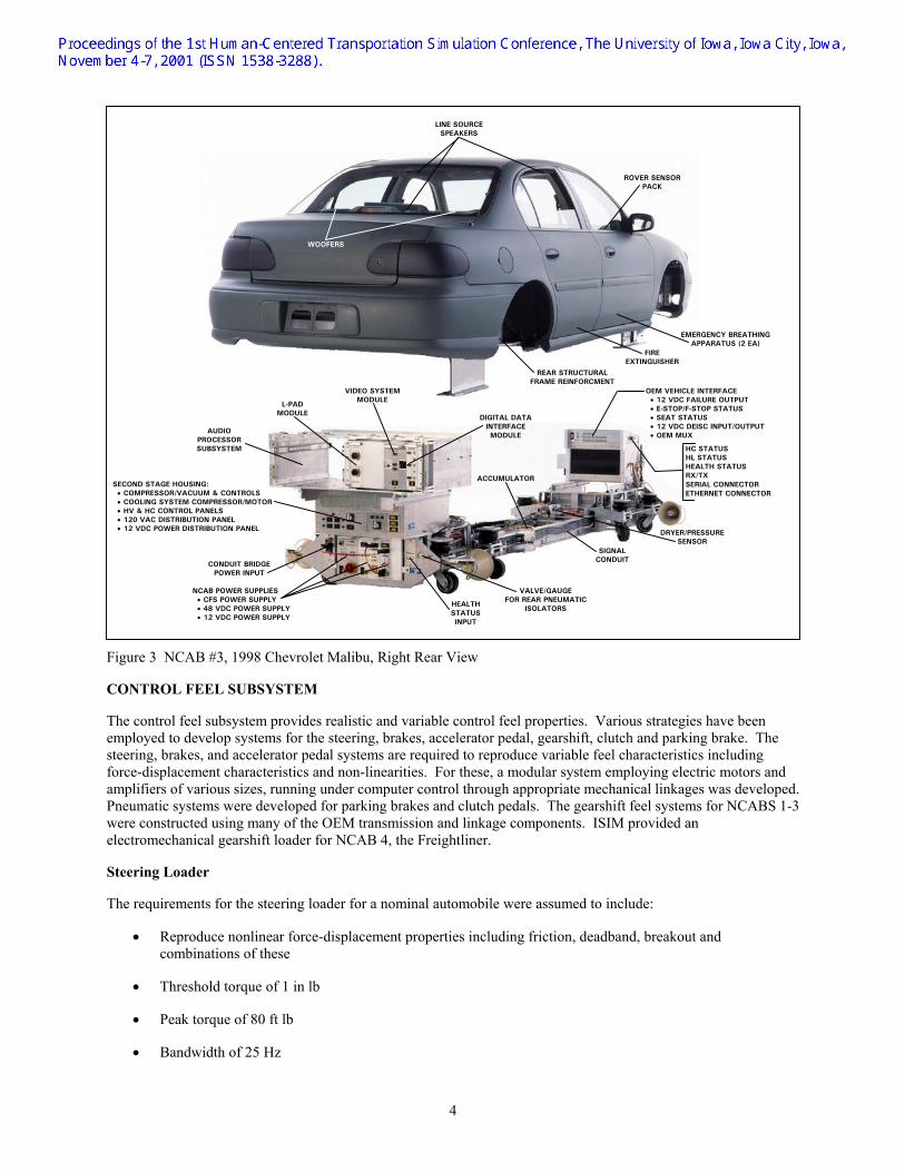
Figure 3 NCAB #3, 1998 Chevrolet Malibu, Right Rear View
CONTROL FEEL SUBSYSTEM
The control feel subsystem provides realistic and variable control feel properties. Various strategies have been employed to develop systems for the steering, brakes, accelerator pedal, gearshift, clutch and parking brake. The steering, brakes, and accelerator pedal systems are required to reproduce variable feel characteristics including force-displacement characteristics and non-linearities. For these, a modular system employing electric motors and amplifiers of various sizes, running under computer control through appropriate mechanical linkages was developed. Pneumatic systems were developed for parking brakes and clutch pedals. The gearshift feel systems for NCABS 1-3 were constructed using many of the OEM transmission and linkage components. ISIM provided an electromechanical gearshift loader for NCAB 4, the Freightliner.
Steering Loader
The requirements for the steering loader for a nominal automobile were assumed to include:
• Reproduce nonlinear force-displacement properties including friction, deadband, breakout and combinations of these
• Threshold torque of 1 in lb
• Peak torque of 80 ft lb
• Bandwidth of 25 Hz
WOOFERS
ROVER SENSOR PACK
EMERGENCY BREATHING APPARATUS (2 EA)
FIRE EXTINGUISHER
REAR STRUCTURAL FRAME REINFORCMENT
DIGITAL DATA INTERFACE MODULE
VIDEO SYSTEM MODULE
L-PAD MODULE
AUDIO PROCESSOR SUBSYSTEM
SECOND STAGE HOUSING: • COMPRESSOR/VACUUM & CONTROLS • COOLING SYSTEM COMPRESSOR/MOTOR • HV & HC CONTROL PANELS • 120 VAC DISTRIBUTION PANEL • 12 VDC POWER DISTRIBUTION PANEL
CONDUIT BRIDGE POWER INPUT
NCAB POWER SUPPLIES • CFS POWER SUPPLY • 48 VDC POWER SUPPLY • 12 VDC POWER SUPPLY
HEALTH STATUS INPUT
VALVE/GAUGE FOR REAR PNEUMATIC
ISOLATORS
ACCUMULATOR
SIGNAL CONDUIT
DRYER/PRESSURE SENSOR
OEM VEHICLE INTERFACE • 12 VDC FAILURE OUTPUT • E-STOP/F-STOP STATUS • SEAT STATUS • 12 VDC DEISC INPUT/OUTPUT • OEM MUX
HC STATUS HL STATUS HEALTH STATUS RX/TX SERIAL CONNECTOR ETHERNET CONNECTOR
LINE SOURCE SPEAKERS

5
• Number of turns lock to lock equivalent to OE
Failsafe mechanisms were provided to help prevent injury to drivers in the event of signal loss or spurious signals.
Parking Brake Pneumatic Emulator Subsystem
The NCAB pneumatic parking brake emulator used on NCABs 1 through 3 provides parking brake lever/pedal force feel representative of an OEM parking brake by using a pressurized pneumatic cylinder installed on the driver's side under the floorpan and attached to the OEM parking brake cable. The assembly is equipped with a pressure gauge, Schrader valve fill port and a pressure sensor.
INTEGRATED AUDIO SUBSYSTEM
The NCABs support the reproduction of high fidelity audio at the driver's design ear point through a suite of installed speakers. The suite includes four woofer and four line source speakers mounted in the passenger compartment. The passenger compartment mounted speakers are installed to provide a uniform sound field at the design ear point of the driver. To achieve this, four non-directional woofer are installed around the driver, one in each front door and one in each rear corner of the passenger compartment. Since sound reproduction of the line source speakers is directional, these assemblies are mounted around the driver with the line-of-sound of the speaker passing through the design ear point. Line sources are mounted to the left and right of the driver in the headliner above the doors, to the rear of the driver on the rear shelf (or in the headliner) and in front of the driver ahead of the steering wheel. Four horns mounted in the wheel wells of the OEM vehicles on the isolation carriages provide tire/road contact noise source reproduction. A tactile sound transducer mounted under the NCAB floorpan on the driver's side provides engine related sound and vibrations.
AUDIO COMMUNICATIONS SUBSYSTEM
The NCAB Audio Communication subsystem supports two duplex voice communication channels between NCAB occupants and other NADS System personnel via the control room based communication subsystem. One channel is a General Communication channel supporting hand free voice communication by NCAB occupants via a headliner console mounted speaker panel and dynamic microphone. The other channel provides headset based communication with the NADS control room via a light weight headset and the interface panel mounted on the passenger side headliner in the vicinity of the B pillar.
HEATING, VENTILATION, AIR CONDITIONING SUBSYSTEM
This NCAB subsystem provides cooling of the passenger compartment to a user specified desired temperature distinct from the outside NCAB temperature e.g., the NADS in-dome temperature. The subsystem utilizes a 3-phase motor driven compressor providing high pressure refrigerant flow to the OEM evaporator. The OEM ventilation subsystem and OEM blower are automatically configured by the NCAB CSCI for re-circulation/Max AC mode for most efficient cooling. The system will operate until the passenger compartment temperature, measured by the headliner console mounted temperature probe, matches the user set reference temperature; and once at temperature the system will regulate about the reference temperature indefinitely. The NCAB CSCI provides status and control of the cooling subsystem via a graphical user interface (GUI) screen.
Ventilation Subsystem
The NCAB Ventilation Subsystem is comprised of three subassemblies:
• A second stage mounted vacuum pump, compressed air pump, embedded controller, and vacuum and pressure switches, check valves, and relay control components
• An engine compartment HVAC user interface control assembly featuring:
• Vacuum switches interfaced to the output of the OEM HVAC mode control switch allowing the state of the switch to be measured by the NCAB CSCI

6
• Vacuum solenoids interfaced to the OEM vacuum registers enabling ventilation duct control by the NCAB CSCI
• The OEM front console mounted OEM ventilation ducts and control registers
The above subsystem elements enable automatic OEM air register configuration via the NCAB CSCI. The HV embedded controller switches the vacuum and compressed air pumps on and off to maintain reservoir conditions within specified bounds.
ENVIRONMENTAL MONITORING SUBSYSTEM
The Environmental Monitoring subsystem enables the continuous monitoring of the NCAB passenger compartment environment. An engine compartment mounted motion reference point sensor pack provides tri-axial acceleration and angular rate accelerations along orthogonal axes. The headliner console is equipped with a temperature probe and sound pressure level meter. In addition a Rover Accelerometer Sensor Pack, equipped with a tri-axial linear accelerometer, is provided with hook and loop strap that enables it to be mounted at a user desired location in the cab.
VIDEO MONITORING SUBSYSTEM
Four remote video cameras equipped with pan and zoom lenses are installed within the NCAB passenger compartment to monitor driver behavior. Two cameras are mounted at the corner of the driver's and passenger's side A pillars with the front console. The camera on the driver's side allows the observation of eye and head movements; the camera on the passenger side allows the observation of center console and sideward directed gaze and control activity. A camera is mounted on the rear of the headliner console allowing observation of secondary control activity over the driver's shoulder. The fourth camera is mounted under the driver's seat looking at the foot and pedal area.
Infrared illumination is used in the driver's foot area to improve image quality at the corresponding low light levels. The illuminator is mounted under the driver's seat.
A Video Module, mounted in the trunk compartment, supports the 4 video signals.
NCAB/NADS STRUCTURAL INTERFACE
Lateral strengthening is the main structural design challenge for a NADS cab module. The OEM vehicle unibody/frame structural design has adequate strength for loads applied in the vertical plane, such as simulated vibration from driving over potholes and curbs. However, under estimated NADS limit motion conditions, arising from possible motion system failures, limit inertial loads can be as high as 9000 lbf. The NCAB features two key load transfer paths for reaction of the inertial load:
• Loads normal to the motion platform surface are reacted via the 4 NADS Vibration Actuators mounted in the wheel wells of the OEM vehicle.
• Shear loads parallel to the motion platform surface are reacted via the 2 NCAB Shear Flexures that are mounted under the front and rear isolation carriages. These flexures make a 3 degree elevation with the platform surface and hence enable shear load transfer with minimal accompanying normal load transfer with the load application point only 0.75 in above the motion platform surface.
An internal NCAB Structural Reinforcement Assembly (SRA) is required to control load transfer from the OEM body to the NADS Motion Platform concentrated load interface points due to the following.
• The thin sheet metal nature of the OEM unibody/frame structure requires control of bearing stress and bending stress during the transfer of such high loads.
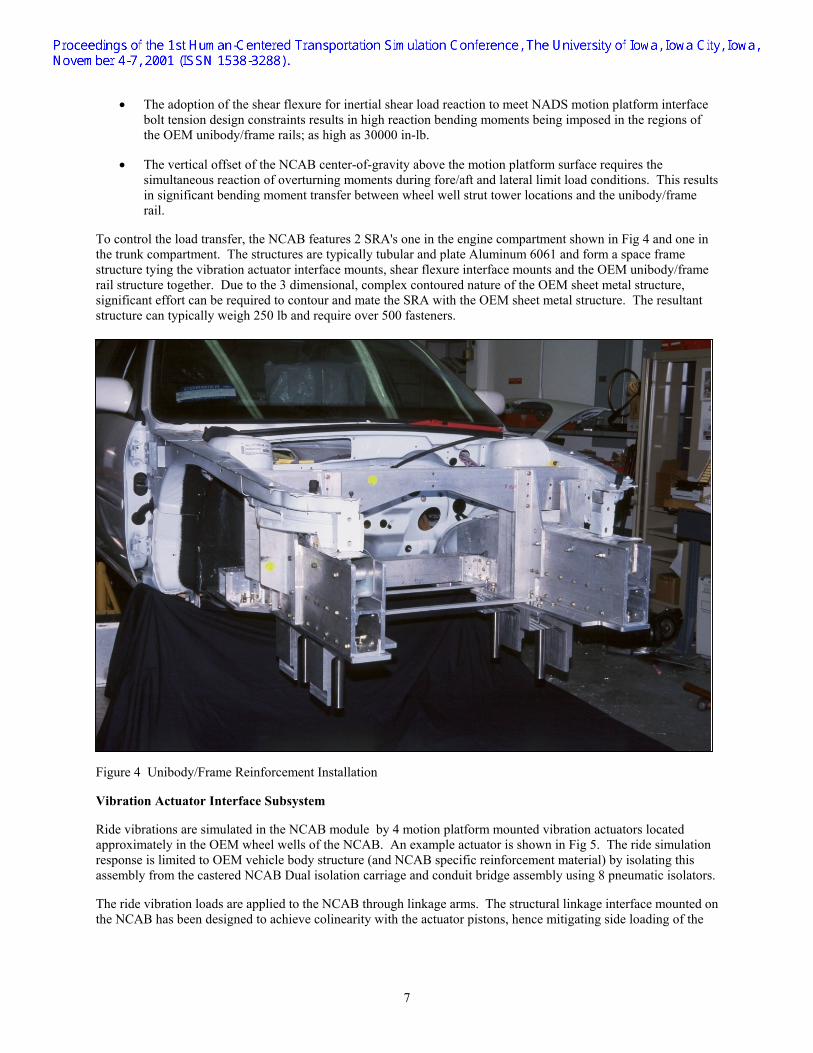
7
• The adoption of the shear flexure for inertial shear load reaction to meet NADS motion platform interface bolt tension design constraints results in high reaction bending moments being imposed in the regions of the OEM unibody/frame rails; as high as 30000 in-lb.
• The vertical offset of the NCAB center-of-gravity above the motion platform surface requires the simultaneous reaction of overturning moments during fore/aft and lateral limit load conditions. This results in significant bending moment transfer between wheel well strut tower locations and the unibody/frame rail.
To control the load transfer, the NCAB features 2 SRA's one in the engine compartment shown in Fig 4 and one in the trunk compartment. The structures are typically tubular and plate Aluminum 6061 and form a space frame structure tying the vibration actuator interface mounts, shear flexure interface mounts and the OEM unibody/frame rail structure together. Due to the 3 dimensional, complex contoured nature of the OEM sheet metal structure, significant effort can be required to contour and mate the SRA with the OEM sheet metal structure. The resultant structure can typically weigh 250 lb and require over 500 fasteners.
Figure 4 Unibody/Frame Reinforcement Installation
Vibration Actuator Interface Subsystem
Ride vibrations are simulated in the NCAB module by 4 motion platform mounted vibration actuators located approximately in the OEM wheel wells of the NCAB. An example actuator is shown in Fig 5. The ride simulation response is limited to OEM vehicle body structure (and NCAB specific reinforcement material) by isolating this assembly from the castered NCAB Dual isolation carriage and conduit bridge assembly using 8 pneumatic isolators.
The ride vibration loads are applied to the NCAB through linkage arms. The structural linkage interface mounted on the NCAB has been designed to achieve colinearity with the actuator pistons, hence mitigating side loading of the

8
actuator piston over the range of NADS operational motion conditions including possible limit loads encountered under emergency stop conditions.
Figure 5 Vibration Actuator Interface
NCAB to Motion Platform Shear Interface Subsystem
The NCAB-to-Motion Platform structural interface provides a reaction load path for inertial forces in the fore/aft and lateral axes of the NCAB that might be experienced as a result of simulated driving maneuvers or limit load conditions arising from possible failures of the NADS Motion Subsystem. Limit load conditions can be as high as 9000 lbf; and reaction of these loads into the motion platform is effected through the NCAB shear flexure interface. The inertial load from the NCAB OEM body is diffused into a Structural Reinforcement Assembly (SRA) in both the engine compartment and trunk/rear compartment of the NCAB; the load is then transferred to within 0.75 in of the motion platform surface via the shear pin assemblies. A standard shear pin assembly foot then interfaces the load with the outboard section of the shear flexure installed under the isolation carriages of the NCAB. The shear flexure has less than a 3 deg elevation angle with the motion platform surface, thus the shear load can be reacted by the motion platform surface with minimal normal loads.
This load transfer mechanism enables shear load reaction while mitigating large tension load application to the motion platform surface tie down bolts; this is a pre-requisite due to the low working tensile load capacity of these bolts resulting from structural characteristics of the motion platform skin.

9
ISOLATION CARRIAGE/CONDUIT BRIDGE SUBSYSTEMS
Each NCAB is mounted on 2 NCAB isolation carriages, which are fabricated from plate aluminum for a maximum strength- to-weight ratio. One carriage weighs approximately 200 lb. The isolation carriages are separated by a conduit bridge, also constructed of plate aluminum, which provides a suitable area for the routing of wiring and cabling. The isolation carriage/conduit bridge subsystem is shown in Fig 6.
Figure 6 Isolation Carriage/Conduit Bridge Assembly with Equipment Racks Installed
Isolation Carriage Subsystem
The carriage assembly is mounted on 8 swivel casters to enable 360 deg of motion. This allows the NCABS to be maneuvered during installation and removal in the NADS dome and over typical industrial surfaces. The 8 casters also provide a low contact force appropriate for rolling on the NADS motion Platform surface.
The carriage also provides structural mounts for electrical equipment enclosures and DIN Standard 19" rack mount equipment weighing up to 120 lb. The Front Isolation carriage houses the Control Feel Subsystem VME chassis. The Cab Interface System (CIS) VME enclosure is mounted on the top mounting flange. The Rear Isolation Carriage houses the NCAB Power Supply Drawer, with the Second Stage Enclosure, housing the compressed air and vacuum pump subsystem and the cooling subsystem compressor, mounted to the top mounting flange. Mounted atop the Second Stage Enclosure is a dual drawer chassis housing the NADS Audio Processor and the Electrical Modules.
A pneumatic isolator suspension reacts the static weight of the NCAB original equipment manufacturer (OEM) body via four pneumatic isolators in the front and the rear isolation carriages. This suspension subsystem provides a

10
method of easily adjusting the height of the OEM body relative to the NADS motion platform by inflating or deflating the pneumatic isolators via the pressure fill ports on the front face of the isolation carriages. It also provides a low stiffness, hence low natural frequency, suspension of the NCAB that works in parallel with the NADS Vibration Actuators to react vertical inertial loads of the OEM body. When the NCAB is mounted on the NADS Vibration Actuators, the pneumatic isolators are adjusted so that they react the static weight of the OEM body, and the vibration actuators are not subject to static load at their mid-stroke position. The low stiffness of the suspension results in minimal restoring force generation when the vibration actuators displace the OEM body vertically through their +- 0.3 in stroke. Limit inertial load forces, resulting from an emergency stop, for example, are reacted by the NADS Vibration Actuators and are not carried by the pneumatic suspension subsystem. The suspension subsystem also isolates all the key NCAB electrical and processing subsystems mounted on the isolation carriage assembly from the NADS ride vibration environment imposed on the OEM body by the NADS Vibration Actuator Subsystem.
Conduit Bridge Subsystem
The front and rear isolation carriages are connected by means of an integrated cable conduit subsystem. This allows point-to-point wiring to be installed between any two points in the NCAB and provides a method of managing the cables.
The conduit bridge provides power distribution throughout the cab module, supplying the range of operational voltages and current required by NCAB mounted equipment, helping to protect the power cables from mechanical damage, and guarding against accidental contact with voltages of 50 volts or more.
The conduit bridge allows for managed power cabling and EMC protection of power buses while supporting multiple power cables. The conduit bridge provides significant growth capacity and allows for power cable addition/removal with minimal NCAB teardown.
The conduit bridge has the following key components:
• Front and rear conduit assemblies, which are designed as an integral part of the Isolation Carriage Assembly in the interests of weight and utility
• One high voltage 250VDC power bus and one low voltage multi-power bus on the left hand side of the NCABs
• One signal conduit on the right hand side of the NCABs
• Conduit covers and modular interface fittings
• Modular plug-in power and signal interface modules supporting interfacing with conduits
NCAB ELECTRONIC EQUIPMENT
Each NCAB contains over 16 cubic feet of electronic equipment, including extra space for the addition of future subsystems. The NCAB equipment suite has been designed to mount DIN standard modules, including 19in drawers, and 6U modules of various widths; to provide a mounting that mitigates exposure to high frequency ride vibration characteristics of the OEM vehicle; and to provide structural support appropriate for the estimated 2.5g emergency stop conditions of the NADS motion environment. The equipment installation is shown in Figs 7 and 8.
Electronic Equipment Mounting
Standardized equipment mounting is common to all NCABs and features:
• A 19-inch drawer in the front isolation carriage supports the Control Feel Subsystem Processor and Pulse Width Modulated Controllers
• A 19-inch drawer in the rear isolation carriage houses the NCAB modular Power Supplies. Power supplies support DC power bus generation

11
Figure 7 Front Electronic Equipment Installation
Figure 8 Rear Electronic Equipment Installation

12
• Two 19-inch drawers mounted on top of the rear isolation carriage in the trunk area of the passenger vehicles support mounting the NADS audio subsystem and fiber optic interface modules. Fiber optics support the interface of digital and video data between NCAB mounted subsystems and the NADS host computer.
Line Replaceable Unit (LRU) Packaging
The NCAB features a modular Line Replaceable Unit (LRU) family of electronics that includes power supply, fiber optic interface, and audio subsystem support modules. Packaging the electronics as LRUs allows:
• Rapid reconfiguration of NCABs by swapping modules between them
• Diagnosis of failure to an individual unit for easy replacement
The LRU modules that make up the NCAB Electronics Equipment are described in the following paragraphs.
Power Supply Module Family
The power supply module family includes the following units:
• 250VDC Power Supply, which provides power for the Control Feel Subsystem (CFS)
• 48 VDC Power Supply, which provides general power to all NCAB subsystems such as VME processors
• 12 VDC Power Supply, which supports all OEM vehicle subsystems
• Controllable Power Supply, which provides a computer controlled power source for cooling fans
Fiber Optic Interface Module Family
The Fiber Optic Interface Module family links digital and video data between the NCAB and the NADS host computer and includes the following units:
• The SCRAMNet/Ethernet Module, which transmits the real-time digital data between the NCAB and the host including:
• Primary control activity by the driver e.g., steering and brake control state
• Secondary control selections by the driver
• Instrument cluster gauge and indicator backdrive values
• Safety data such as redundant acceleration and sound pressure level data
• The Video/Entertainment Module, which transmits video data from four cameras mounted inside the NCAB to both the NADS operator and the research control stations. It also translates the Controllable Power Supply emulated radio frequency transmissions of the OEM entertainment subsystem.
NCAB CAB INTERFACE SUBSYSTEM
To support driver behavior studies, the NCAB Cab Interface Subsystem (CIS) allows the monitoring of all control selections by the driver, and controls the information displayed to the driver based upon requests made by the NADS host computer, providing functional OEM vehicle displays and controls through the following features:
• Multiple power bus structure supporting OEM vehicle subsystems and NCAB processor operation

13
• An OEM wiring signal conditioning and interface card suite that provides the necessary electrical conditioning between the NCAB processor hardware input/output subsystem and the OEM wiring subsystem
• A wiring interface harness featuring over 200 point-to-point interconnections with the OEM wiring harness
• NCAB Graphical User Interfaces supporting the setting of displays and reading of secondary controls
Cab Interface System Functions
Information displayed to the driver by the CIS under NADS host computer control includes:
• Analog or digital data displays for speed, engine rpm, fuel level
• Alert indicators for brake and airbag warning lights
Driver control selections that are monitored from the NCAB CIS include the following:
• Headlights and turn signals
• Radio tuning and controls
• Heating, ventilation and air conditioning (HVAC) controls (vent configuration, blower speed and temperature selection)
• Power mirrors and power seat
• Ignition switch
• Cruise Control
Custom wiring harness
The custom wiring harness conducts over 200 signals within the passenger compartment and provides interface with all secondary controls and displays supported by appropriate signal conditioning with a standard interface between the OEM vehicle firewall and the CIS processing subsystem.
Dual high and low current power feed and return wiring subsystem
The dual high and low current power feed and return wiring subsystem mitigates ground plane sensitivity to high current OEM subsystems.
Signal conditioning subsystem
The signal conditioning subsystem supplies all analog and discrete input and output to support channel-specific gain adjustment and current pull up or pull down circuitry needs. The Digital Electrical Interface Card (DEIC) family was specifically designed for this purpose. Up to 160 data channels can be supported in two slots of a standard 6U VME chassis. This is approximately three times the density of existing DIN standard components and is prerequisite to subsystem implementation in the confines of the engine compartment.
Cab Interface VME Subsystem
The CIS VME subsystem is housed in the sloping roof enclosure located in the engine compartment of NCABS 1 through 3, and behind the cab in NCAB 4. The enclosure houses a multi board Motorola 2604 based processing subsystem with supporting signal conditioning and interface boards
The primary function of this subsystem is to enable operation of OEM vehicle subsystems through:

14
• Sampling of secondary control state for transmission to the NADS/SDM host
• Backdrive of information and alert subsystems based upon NADS/SDM hosts state
• Sampling of environmental variables for the passenger compartment interior for use by the NADS/SDM Safety systems
• Supports control and status determination of the NCAB cooling subsystem embedded controller located in the rear second stage enclosure of the NCAB
The data transmission to/from the NADS host is accomplished by means of RTEX services by the Motorola 2604 board via the fiber optic based SCRAMNet interface.
The VME 14 slot chassis supports the following systems:
• One Motorola 2604 board supporting fiber optic based digital reflective interface with the NADS host computer
• One Motorola 2604 board supporting sampling and backdrive of all OEM vehicle subsystems
• Three Industry Pack (IP) carriers to mount up to 12 IPs
• Mounting of the DEIC signal conditioning card family
• An electromagnetic compliant enclosure housing the processing subsystem and allowing ease of connection for input and output signals for OEM vehicles featuring multiplexed subsystems, and the VME subsystem supporting a serial multiplexed interface that drives all OEM instrument cluster related functions. The interface is implemented through existing OEM connectors where possible.
The front console may be completely removed using OEM maintenance procedures in addition to disconnecting 4 additional connectors.
DIGITAL ELECTRICAL INTERFACE CARD SUBSYSTEM
The Digital Electrical Interface Card (DEIC) family supports the interfaces between the analog OEM subsystems and the CIS VME processing subsystem Industry Pack hardware input/output cards via the NCAB OEM wiring interface harness, and also between the multiplexed OEM subsystems and the CIS VME serial port. Note that NCAB 1 does not feature this functionality since it is a fully analog OEM system.
In the conversion process from the OEM vehicle to the NCAB, all OEM electrical wiring is removed with the exception of the OEM wiring within the passenger compartment. To achieve full functionality of the OEM passenger compartment subsystems, several functions must be provided by the Digital Electrical Interface Card system. For displays, such as speedometer, tachometer, and fuel gauge, the original source of the electrical input (e.g., fuel level sender) to the display must be removed from the NCAB. The DEIC provides the necessary current drive capability to regulate the display in response to CIS digital specified values that are received from the NADS/SDM Host. For secondary controls such as the headlamp or cruise selector the OEM load (e.g., headlamp resistive load) must be removed. The DEIC provides a current limiting small emulation load, which provides a measurable voltage change for different control selector positions that can be read either by analog to-digital conversion or discrete input channels of the CIS and provided to the NADS/SDM Host.
The DEIC family is made up of analog interface cards and multiplexed OEM interface cards. There are 2 designs of analog DEIC interface cards. A 40 channel discrete input/output card and an 8 channel analog input/output card. Both cards can only be configured either as input or output cards since the card is interfaced directly with an Industry Pack family of I/0 modules. The multiplexed OEM systems interface cards support serial interfacing with the OEM vehicle specific multiplexed signal protocol.

15
DIGITAL DATA SCRAMNET/ETHERNET INTERFACE SUBSYSTEM
The NCAB Digital Data Interface Module provides digital data connectivity to the NADS/SDM host subsystem for 2 SCRAMNet Nets and a 100-Baset Ethernet connection; the transmission to the NADS/SDM facility is effected over fiber optic cables in the NCAB Umbilical.
The NCAB Digital Data Interface Module supports breakout of the 12 fiber optic umbilical cable into: a within NCAB module SCRAMNet Transmit (Tx) and Receive (Rx) Fiber Optic Cable ring; a 100-Baset Ethernet Hub supporting an NCAB Ethernet network of seven ports.
The within NCAB Fiber Optic Cable ring supports dual net connectivity between the CIS, CFS and Audio Processor subsystems by daisy chaining the TX port of one unit to the RX port of the next.
NCAB INTERIOR TRIM
To provide an interior trim equivalent to OEM vehicle standards, custom vacuum formed ABS plastic encases NADS-specific equipment installed inside the NCAB passenger compartment. The color is closely matched to that of the OEM vehicle trim.
Custom Trim Components
Due to the unique interior of each OEM vehicle, vacuum-formed items typically require the following custom handling:
• Detailed measurement of OEM vehicle contours
• Detailed design and prototyping of the trim
• Detailed design and fabrication of a medium density fiber board mold for use in the vacuum forming process
• Custom contouring and mating the trim to the OEM vehicle interior
Headliner Console
Mounted along the centerline of the NCAB, the headliner console, shown in Fig 9, encases safety and communication subsystem components. This location makes emergency switches accessible to both the driver and front passenger. Also, equipment mounted in the headliner does not interfere with the driver's field of view. The headliner console components include:
• Safety subsystem manual controls including the emergency and fire stop switches, and redundant safety sensors for sound level and temperature measurements
• Video camera mounted to view over the driver's shoulder
• Speaker and microphone for communication between NCAB occupants, simulator operator, and researchers

16
Figure 9 Headliner Console
Line source tweeters and woofers
Four tweeter and woofer assemblies are installed in the NCAB passenger compartment. They reproduce high fidelity audio simulation of sounds such as passing vehicles and wind noise. The speakers are submerged into the OEM vehicle structure and covered with custom trim.
SAFETY SUBSYSTEM
The NCAB system provides human and equipment hazard mitigation under both operational and maintenance environments through a broad range of subsystem functionality and attributes including:
• A passive restraint system including the OEM vehicle 3 point harness and an additional lap belt for front seat occupants
• A safety control panel providing the user direct access to Emergency Stop and Run_Consent signals under all conditions
• Sampling of NCAB environment data (Sound Pressure Level, temperature, X, Y and Z linear acceleration and angular rates) for communication (by RTEX System services) to NADS/SDM safety systems for monitoring and control purposes
• Passenger compartment emergency equipment, including two 5 minute emergency breathing apparatus, a fire extinguisher, a flashlight, and a first aid kit

17
Non-OEM subsystem components featured within the passenger compartment (e.g., integrated audio subsystem speakers, cameras) have been installed so as to mitigate possible mechanical impact hazard for the occupants under NADS motion conditions by:
• Recessing the equipment into the interior of door panels and headliner conduit cavities to minimize protrusion into the passenger compartment
• Providing OEM equivalent ABS vacuum formed trim for the exposed fascia of the installed units; the plastic fascias feature rounded contours and compliant surfaces in an effort to prevent occupant contact with angular metallic features of the installed equipment
• Providing tethered restraint for detachable units
NCAB Subsystems are labeled with safety and warning labels as appropriate.
SYSTEM DEVELOPMENT MODULE
A System Development Module (SDM) is an adjacent facility to support the use of an NCAB in a fixed base environment. In addition to the NCAB, the NADS systems required to accomplish this are:
• An image generator and projection system
• Roadway database
• Vehicle dynamic models and processors
• Data acquisition system
• Capability for data input/output and other communication with the NCAB
An SDM can be used for experimental setup and checkout in preparation for studies on the NADS motion base. In conjunction with an NCAB it can also serve as a facility for experiments that do not require the large motion provided by the NADS.
The overall NADS facility is planned to provide an SDM for setup and preparation and for studies that do not require motion. Organizations with their own NCAB can also use an in-house SDM to maximize the use of the NCAB, and pertinent NCAB interface documents are available.
STEPS IN DESIGNING AND DEVELOPING ADDITIONAL NADS CABS
The NCABS described in this paper have been developed as a part of the overall NADS effort, and as such are part of that facility. Other organizations may find it useful or desirable to have an NCAB of their own. Possible reasons for this include:
• Specific vehicle configuration
• Confidential equipment or features
• Enhanced or reduced capabilities compared to NADS owned cabs
• Ability to perform experiments in the NADS as well as in-house using a System Development Module (SDM) or other in-house simulator capabilities
The steps in designing and developing such a cab include:
• Define user requirements and possible simulator applications
• Determine SDM interest or needs

18
• Identify example vehicle
• Determine cab functionality, features
• Develop cab specifications
• Obtain actual vehicle or cab as the basis for modification
• Perform preliminary mechanical design
• Establish geometry: platform, eyepoint, etc.
• Plan and analyze structures
• Perform preliminary design of other systems
• Review preliminary design with user and NADS Staff
• Resolve issues, obtain approval
• Prepare final plan and schedule
• Disassemble vehicle, prepare for modification
• Perform detailed designs
• Fabricate cab
• Perform systems integration and checkout
• Complete in-plant acceptance tests
• Ship to user's plant or NADS facility
• Perform integration, functional and acceptance tests at user's plant or NADS facility
• Provide documentation
• Perform training
• Support maintenance, spares, and other follow-up activities
SUMMARY
Four NCABS, representing a range of vehicle types, have been developed to the NADS specifications. These cabs incorporate systems that help provide for a realistic driving environment and satisfy the requirements for communications with the various NADS systems. They are designed to meet the current and anticipated needs of NADS users for the foreseeable future.