the dry carbonate process - national energy technology ... library/research/coal/ewr/co2/dry... ·...
TRANSCRIPT
RTI International is a trade name of Research Triangle Institutewww.rti.org
Thomas Nelson, Luke Coleman, Matthew Anderson, Joshua Herr, Maruthi Pavani
RTI International - Center for Energy Technology
The Dry Carbonate Process:Carbon Dioxide Recovery from Power Plant Flue Gas
Annual NETL CO2 Capture Technology for Existing Plants R&D Meeting
March 24 – 26, 2009 • Sheraton Station Square • Pittsburgh, Pennsylvania

2
www.rti.org
RTI InternationalCenter for Energy Technology (CET)
RTI International• Established in 1958• One of the world’s leading research institutes• > 2,800 staff; > $700M revenue (2008)• Mission: to improve the human condition
by turning knowledge into practice
CET Capabilities• Advanced Gasification
– Warm gas desulfurization– Multicontaminant removal– Substitute natural gas production
• Carbon Capture– Post- and Pre-combustion CO2 capture– Chemical Looping Combustion– Advanced Membranes
• Clean Fuels– Syngas to fuels and chemicals– Biofuels
• Hydrogen Production and Purification
Clean FuelsCarbon Capture
Catalyst/Sorbent Synthesis
CET Application Areas
Membrane Separations
Process Development and Scale-up

3
www.rti.org
Project Background
4
www.rti.org
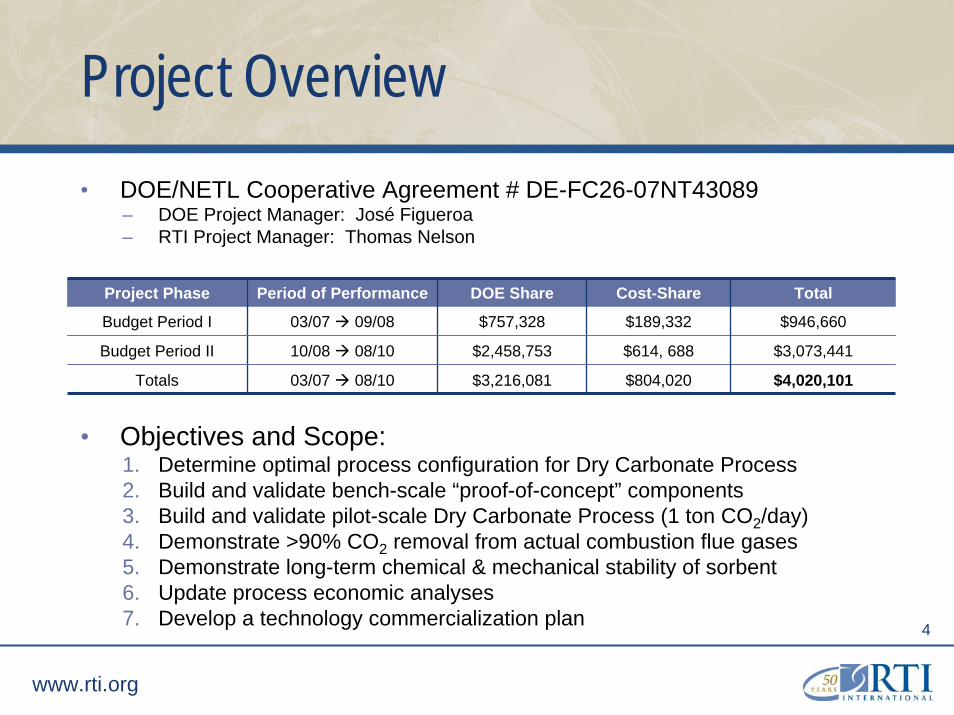
Project Overview• DOE/NETL Cooperative Agreement # DE-FC26-07NT43089
– DOE Project Manager: José Figueroa– RTI Project Manager: Thomas Nelson
• Objectives and Scope:1. Determine optimal process configuration for Dry Carbonate Process2. Build and validate bench-scale “proof-of-concept” components3. Build and validate pilot-scale Dry Carbonate Process (1 ton CO2/day)4. Demonstrate >90% CO2 removal from actual combustion flue gases5. Demonstrate long-term chemical & mechanical stability of sorbent6. Update process economic analyses7. Develop a technology commercialization plan
Project Phase Period of Performance DOE Share Cost-Share Total
Budget Period I 03/07 09/08 $757,328 $189,332
$614, 688
$804,020
$946,660
Budget Period II 10/08 08/10 $2,458,753 $3,073,441
Totals 03/07 08/10 $3,216,081 $4,020,101
5
www.rti.org
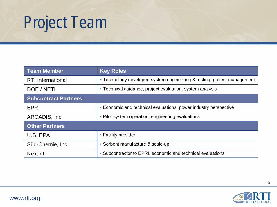
Project Team
Team Member Key RolesRTI International • Technology developer, system engineering & testing, project management
DOE / NETL • Technical guidance, project evaluation, system analysis
Subcontract PartnersEPRI • Economic and technical evaluations, power industry perspective
ARCADIS, Inc. • Pilot system operation, engineering evaluations
Other PartnersU.S. EPA • Facility provider
Süd-Chemie, Inc. • Sorbent manufacture & scale-up
Nexant • Subcontractor to EPRI, economic and technical evaluations

6
www.rti.org
Technology Background

7
www.rti.org
RTI’s Dry Carbonate Process for CO2Capture from Flue Gas
FGD CO
2Ad
sorb
er
Reg
ener
ator
Sta
ck
Comp.
CO22200 psiaCO2Recycle
Flue GasLow CO2
Flue GasHigh SO2High CO2
Flue GasLow SO2
High CO2 + H2O
CO2+ H2O
Hot SorbentNa2CO3
Cooled SorbentNa2CO3
CO2-Loaded SorbentNaHCO3
Water
FGD CO
2Ad
sorb
er
Reg
ener
ator
Sta
ck
Comp.
CO22200 psiaCO2Recycle
Flue GasLow CO2
Flue GasHigh SO2High CO2
Flue GasLow SO2
High CO2 + H2O
CO2+ H2O
Hot SorbentNa2CO3
Cooled SorbentNa2CO3
CO2-Loaded SorbentNaHCO3
Water
60°C1 atm
120°C1 atm
Na2CO3 (s) + CO2(g) + H2O(g) ↔ 2NaHCO3(s)
60°C

8
www.rti.org
The Dry Carbonate ProcessCloser Look at Reaction Chemistry
CO2 Adsorption (Carbonation)
Exothermic ΔHr° = -1325 Btu/lb CO2
Operating temperature: < 80°C
Sorbent Regeneration
Endothermic ΔHr° = 1325 Btu/lb CO2
Operating temperature: > 100°C
Contaminants
Reactions with SO2 and HCl are irreversible at process conditions
No observed effects by O2, Hg, and NOx
Na2CO3 (s) + SO2 (g) + ½O2 (g) → Na2SO4 (s) + CO2 (g)Na2CO3 (s) + 2HCl(g) → 2NaCl (s) + CO2 (g) + H2O (g)
Na2CO3 (s) + CO2(g) + H2O(g) ↔ 2NaHCO3(s) 2NaHCO3(s) ↔ Na2CO3(s) + CO2(g) + H2O(g)

9
www.rti.org
Advantages of a Na2CO3-based CO2 Capture Process (Compared to conventional amine technology)
• Lower total regeneration energy requirement
• Lower CO2 removal cost – capital savings; operating costs; sorbent make-up savings
• No flue gas pretreatment – No heating, No cooling, No guard beds
• Tolerance to contaminants in flue gas (e.g., O2, SO2, HCl)
• Readily available and inexpensive sorbent
• Non-hazardous and non-toxic sorbent
• No hazardous waste generated

10
www.rti.org
Challenges of CO2 Capture with a Na2CO3-based Process
• Large solids handling/circulation requirements– Best-case scenario → Na2CO3 : CO2 = 2.4 : 1 (mass ratio)Solution: High capacity sorbents; best available solids handling technologies
• Exothermic CO2 sorption affects reaction equilibrium– CO2 capture is heat transfer limitedSolution: Reactor design is critical; target designs with highly effective heat transfer
• CO2 removal requires equimolar amount of waterSolution: Target saturated flue gas (downstream of wet FGD); water added if required
• Na2CO3 reacts irreversibly with SO2 and HCl at process conditionsSolution: Continuous sorbent make-up; SO2 guard bed may improve economics
• Raw Na2CO3 is not physically strongSolution: Engineered sorbent (binders / support materials)
• Condensed water causes raw Na2CO3 to agglomerateSolution: Engineered sorbent; reactor operation above flue gas dew point
11
www.rti.org
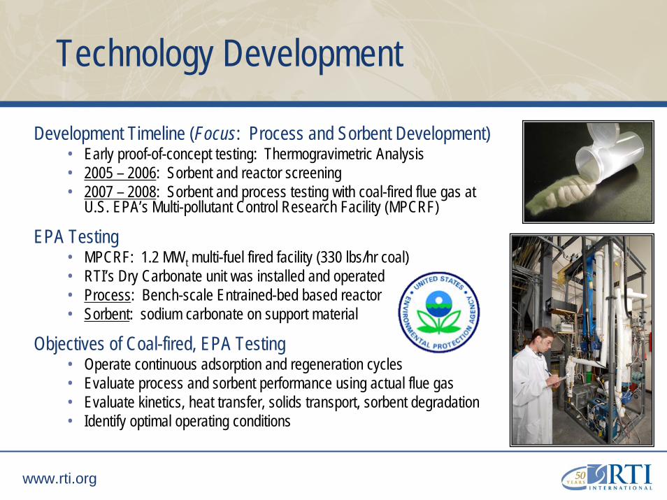
Technology Development
Development Timeline (Focus: Process and Sorbent Development)• Early proof-of-concept testing: Thermogravimetric Analysis• 2005 – 2006: Sorbent and reactor screening• 2007 – 2008: Sorbent and process testing with coal-fired flue gas at
U.S. EPA’s Multi-pollutant Control Research Facility (MPCRF)
EPA Testing• MPCRF: 1.2 MWt multi-fuel fired facility (330 lbs/hr coal)• RTI’s Dry Carbonate unit was installed and operated• Process: Bench-scale Entrained-bed based reactor• Sorbent: sodium carbonate on support material
Objectives of Coal-fired, EPA Testing• Operate continuous adsorption and regeneration cycles• Evaluate process and sorbent performance using actual flue gas• Evaluate kinetics, heat transfer, solids transport, sorbent degradation• Identify optimal operating conditions

12
www.rti.org
Field Testing of the Dry Carbonate Unit
RTI CO2 Capture Test Unit - EPA TestingNatural Gas Combustion (CO2 Concentration ~ 6 vol%)
0
1
2
3
4
5
6
7
0 30 60 90 120 150 180 210
Time (min)
CO
2 C
onc
(vol
%)
CO2 Conc. (vol%)
CO2 concentration of flue gas after WFGD (~6 vol%)
CO2 concentration in Gas-Solid ContactorAfter flue gas mixes with aeration gas (~ 4 vol%)
Start sorbent flow
Stopped sampling to clean filter
Natural Gas Combustion Test Flue gas flowrate: 20 SCFHAverage CO2 Capture: 96.5%
Maximum CO2 Removal ~ 98%
Highlights• Thousands of hours of sorbent circulation testing• Hundreds of hours of combustion flue gas testing
Natural Gas Combustion• CO2 in flue gas: ~6 vol% (before dilution)• Maximum CO2 removal achieved: ~99%
Coal Combustion• CO2 in flue gas: ~10.5 vol% (before dilution)• Maximum CO2 removal achieved: ~92%• Sustained > 90% capture over many cycles• No negative effects due to contaminants
Lessons Learned• Heat control in adsorber is critical for CO2
capture rate – reactor design must be optimized• Sorbent CO2 working capacity was not
sufficient for economical operation of process

13
www.rti.org
Current Research & Development

14
www.rti.org
Dry Carbonate Process
• RTI has selected an isothermal, moving, fluidized-bed design for further scale-up• Most commercially- and technologically-feasible embodiment of the Dry Carbonate Process• Design specifically addresses key process challenges
• Focus on scale-up: Dry Carbonate pilot unit capable of 1 ton/day CO2 capture
Heat Transfer• Achieves maximum heat transfer rates• Dedicated heating/cooling service systems• Commercial: Coal dryers, Circulating fluidized-bed combustors
Reaction Rate• Maximizes thermodynamic and concentration driving forces• Maximizes gas-solid contacting• Permits counter-current gas-solids contacting
Solids Handling• Permits gravity feeding through reactor• Simple gas-solid separation• Commercial: Used in mining, cement plants, power plants

15
www.rti.org
RTI’s Development Approach
Development Areas Approach
Improved Sorbent CO2 Capacity • Modify sorbent recipe• Screen candidates in lab-scale CO2 adsorber
Heat Transfer Evaluation• Bench-scale heat transfer system• Measure heat transfer coefficients• CFD Modeling
Operate in Moving-bed Mode • Bench-scale evaluation of moving-bed contactor
Evaluate Solids Handling / Control • Consult with solids/fluidization experts• Bench-scale evaluation of conveyors and control valves
Develop Process Design & Sizing • Detailed engineering and design for 1 ton/day pilot unit• Bench-scale evaluation of heat transfer arrangements
RTI’s ongoing R&D effort to prepare for 1 TPD CO2 capture unit:

16
www.rti.org
Sorbent Development Program
• R&D Scope of Work:• Construct sorbent test station• Improve sorbent CO2 capacity• Improve sorbent CO2 capture rate• Maintain acceptable attrition resistance• Scalable manufacturing procedure
• Expected Results• Na2CO3-based sorbent having a minimum dynamic CO2
capacity of 10 wt%• Sorbent with an optimized CO2 capture rate• Attrition resistance consistent with commercial materials
used in fluidized-bed applications• Production of 200 lb “validation” batches of best-performing
sorbents by our partner, Süd-Chemie, Inc.• Production of several thousand pounds of optimized sorbent
by Süd-Chemie, Inc.
StatusCompleteCompleteIn ProgressIn ProgressMay 2009
Time [min]

17
www.rti.org
Improved Sorbents
SorbentDensity[g/cm3]
Davidson Attrition Index
CO2 Capacity[wt%]
Supported-Na2CO3
0.96 12 2.2
Sorbent A 0.67 29 13.3
Sorbent B 0.57 23 16.3
Sorbent C 0.65 32 24.3
Lab-scale CO2 Sorbent Test Station
• April / May 2009: Scale-up at Sud-Chemie manufacturing plant
18
www.rti.org
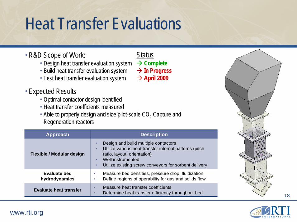
Heat Transfer Evaluations• R&D Scope of Work:
• Design heat transfer evaluation system• Build heat transfer evaluation system• Test heat transfer evaluation system
• Expected Results• Optimal contactor design identified• Heat transfer coefficients measured• Able to properly design and size pilot-scale CO2 Capture and
Regeneration reactors
Approach Description
Flexible / Modular design
• Design and build multiple contactors• Utilize various heat transfer internal patterns (pitch
ratio, layout, orientation)• Well instrumented• Utilize existing screw conveyors for sorbent delivery
Evaluate bed hydrodynamics
• Measure bed densities, pressure drop, fluidization• Define regions of operability for gas and solids flow
Evaluate heat transfer • Measure heat transfer coefficients• Determine heat transfer efficiency throughout bed
StatusCompleteIn ProgressApril 2009

19
www.rti.org
Vertical Screw Conveyor
Vertical Screw Conveyor
Fluidized-bed,Gas-Solids Contactor
Chilled Water
Fluidization Gas
Heat Transfer EvaluationsProcess and Instrumentation Diagram
20
www.rti.org
CFD ModelingSupport for bench-scale and pilot-scale R&D
• R&D Scope of Work• Validate MFIX model with experimental results• Develop MFIX predictive model to guide reactor designs
• Expected Results• Functional model to predict how design of heat transfer internals
affects hydrodynamic and heat transfer properties• Fundamental understanding of:
• gas/solids movement• mass transfer• heat transfer between gas-solid-surface
• Reduced time to select optimal contactor designs for heat transfer system and 1 TPD pre-pilot unit
StatusIn ProgressIn Progress

21
www.rti.org
Solids Handling and Control
• R&D Scope of Work• Evaluate solids control valves• Pneumatic conveying of carbonate sorbent• Evaluate gas-solids separation and filtering• Consult with solids handling experts
• Expected Results• Determine optimal solids control technique for 1 TPD• Determine operating ranges for pneumatic conveyor• Determine optimal gas-solids separation technique
• Approach• Utilize solids flow equipment developed under DOE-
funded project DE-FG36-04GO14312• Parametric testing of control valves, seals, conveying,
and separation techniques
StatusIn Progress

22
www.rti.org
Design of Pilot-Scale Dry Carbonate Process
• Pilot-scale: 1 ton per day CO2 Capture Unit
• Sizing:
• Modular design
• Current work: sizing, reviewing fabrication needs, creating PFDs and P&IDs, process control
Flue Gas In
CO2-LeanFlue Gas
Low-pressure CO2
CO2
Capt
ure
Reac
tor
Rege
nera
tor
CO2 Captured (90%) 2000 lbs/day, 84 lbs/hr
Flue Gas Flowrate (wet) 8,730 SCFH
Initial Sorbent Loading 1,500 lbs
Sorbent Circulation 500 – 1500 lb/hr
Sizing of Test Unit 12’ tall - 4’ X 4’ footprint
Cooling Load (water) 10 gpm
Heating Load (steam) 140 lb/hr

23
www.rti.org
Path Forward

24
www.rti.org
EPA Field Testing of Pilot Dry Carbonate Process
Objectives:• 2,500 hours online• Utilize 10-20% slipstream of flue gas• Multiple coals: bituminous, sub-bit., lignite
Expected Outcomes:• Long-term reliability proven• True measure of:
– sorbent attrition– sorbent degradation– regeneration gas purity
• Parametric/sensitivity studies exhibit optimal conditions for Dry Carbonate Process

25
www.rti.org
Slipstream Test Unit Design
Project Objective: Design for next scale-up phase –Slipstream Test Unit (STU)
Sizing: 5 MW equivalent slipstream at utility site
Potential demonstration site:• UNC Chapel Hill power plant• Power equivalent: ~ 60 MWe• CO2 produced: ~ 1500 tons/day• Potential to utilize plant for additional testing of 1 TPD unit
CO2 Captured (90%) ~100 tons/day
Flue Gas Flowrate (wet) 700,000 SCFH
Initial Sorbent Loading 125,000 lbs
Footprint 400 – 500 ft2
Cooling Load (water) 500 gpm
Heating Load (steam) 10,000 lb/hr
StackBaghouse
Coal Bunker
Limestone
Admin Building
Enclosed CFBs
UNC Chapel Hill Coal-fired power plant
Source: Microsoft Live Maps

26
www.rti.org
Detailed Economic Analyses
• Current work: Independent analyses of Dry Carbonate Process by EPRI and Nexant• Phase I: Update cost analysis for new process design (Apr 2009)• Phase II: Comprehensive technoeconomic analysis of Dry Carbonate Process (2010)
– Baseline: Fluor’s Econamine FG+ CO2 capture process– Utilize data from pilot-scale testing
• Expected Outcomes: CAPEX, OPEX, Power Performance, Novel heat integration schemes, novel compression schemes
• Previous Preliminary Analyses:Cost Summary No CO2 Capture1 With CO2 Capture
(MEA)1With CO2 Capture(Dry Carbonate)
Net Plant Power (MWe) 462 329 381
Total COE, c/kWh 5.51 8.73 7.46
$/ton CO2 removed NA 29.2 17.7
Total Plant Capital Requirement ($ X 1000) $ 591,714 $ 733,000 $ 695,598
1 Source: “Evaluation of Innovative Fossil Fuel Power Plants with CO2 Removal”, DOE/EPRI, 1000316, December 2000

27
www.rti.org
Development Timeline
2010 2011 2012
Process Related
Sorbent Related
Economics Related
Heat Transfer Studies
Cold-Flow Studies
Construction of 1 TPD Pilot & CUP testing
EPA Field Testing Slipstream Test Unit (STU)Construction Shakedown
Experimental Batches (50 lbs)
Pilot Batch (3,000 lbs)
Batch for STU (200,000 lbs)
Preliminary Economics
Comprehensive Technical & Economic Analyses
Construction Shakedown & TestingDesign & Engineering
Budget Period II Next Development Phase

28
www.rti.org
Path to Commercialization
2001Laboratory and “proof of concept”studies
2005RTI field testing proves feasibility of dispersed gas-solid reactor design
2007Bench-scale system successfully tested at coal-fired research facility
2003Novel CO2 capture sorbent developed based on supported sodium carbonate
2010Pilot-scale demonstration of technology – up to 1 ton CO2captured per day
2012Large-scale demonstration at utility company site – 100 ton CO2captured per day
>2015Commercial Technology
Development timeline for RTI’s Dry Carbonate Process

29
www.rti.org
Acknowledgements
RTI would like to thank the Department of Energy – National Energy Technology Laboratory for the financial support on this project through Cooperative Agreement DE-FC26-07NT43089
Also, RTI would like to thank the following individuals for their technical guidance and feedback to the project:
– José D. Figueroa (DOE-NETL, Project Manager)– Tom Feeley, Sean Plasynski, and Jared Ciferno (DOE-NETL, Technology Managers)– Gunnar Henningsen (Consultant)– Carl Singer and Wojciech Jozewicz (ARCADIS, Inc)– John Wheeldon / Gerry Choi (EPRI / Nexant)– Nick Hutson and Will Yelverton (U.S. EPA)– Tom Pusty, Jeff Braden, and Troy Walsh (Süd-Chemie, Inc)– Sharon Sjostrom, Richard Schlager, and Paul Brignac (ADA-ES)– Ted Knowlton (PSRI)