the early eighties: development of in-flight transfer ... · the early eighties: development of...
TRANSCRIPT

The Early Eighties: Development of In-Flight Transfer
Alignment—Challenges and Methods
Zeev Berman*
Berman Consulting and Training Ltd, Kinneret, 15105, Israel
email:[email protected]
Abstract. In the late seventies and early eighties, Rafael devolved a very ad-
vanced (at the time) transfer alignment algorithm. This required the develop-
ment of an entire infrastructure for navigation work: strapdown navigation
equations, navigation error model, Kalman filter implementation, system level
error model, inertial measurement unit, real-time, floating-point computer, test
design, implementation and analysis. This paper tells the story of this enter-
prise, from the preliminary studies to successful operational deployment, by
pointing out the different phases and lessons learned.
1 Introduction
This paper is about the development of a navigation system, and touches on a very
wide range of engineering topics related to navigation systems. The main goal of the
paper is to describe the people, decisions, challenges, problems, and solutions during
this project. The dilemma was deciding on the extent to which the underlying engi-
neering and mathematical topics should be detailed. The decision was ultimately
made to write a paper without equations, mainly because the subject is so broad that
once I started writing equations, I would not know where to stop. Moreover, the main
objective of the paper is to provide the reader, who is not necessarily a navigation
expert, a history background of the technical achievements. Those who are missing
the equations are directed to references in which the relevant ones are described. Of
course, the best descriptions are in Itzhack Bar-Itzhack's technical documents.
Itzhack Bar-Itzhack is one of the key individuals in this story. Like many others, I
learned a lot from Bar-Itzhack: I took his course at the Technion and read his bro-
chures, which were always on his desk. We knew each other pretty well: Bar-Itzhack
worked as a consultant at Rafael; we even played volleyball together. Nevertheless,
although the paper is being published in the Itzhack Y. Bar-Itzhack Memorial Sympo-
sium, it is not a dedicated memorial to the man. Its main purpose is to depict a picture
of engineering challenges and the progress in their achievements.
* CEO, web-site: http://www.bermanconsult.com
To maintain a continuous flow in the paper, we present here, for non-experts, a
short description of the technical terms used in the sequel (see [13] for more details).
Accelerometer – an instrument that measures a specific force (acceleration com-
bined with gravity effect).
Gyro – an instrument that measures angular rates.
IMU (Inertial Measurement Unit) – a unit composed of accelerometers and gyros
to measure specific forces and angular rates in three orthogonal axes.
Inertial Navigation – a method to calculate position, velocity and angular position
from initial conditions and accelerometer and gyro outputs.
Stabilized Platform Navigation System – an inertial system with accelerometers in-
stalled on a stabilized gimbal.
SD (Strapdown) Navigation System – an inertial system without any stabilizing
gimbals. It is stiff with respect to the body to which it is attached.
SD Navigation Algorithm – an algorithm that integrates the IMU outputs to provide
position, velocity and angular position where the IMU is installed rigidly with the
body to be navigated.
Transfer Alignment – a method of finding attitude (orientation) of a navigation sys-
tem from a velocity (or position) reference. To achieve this, the reference data are
provided for a certain time and some maneuver during this phase is required. The
standard implementation is based on Kalman filtering (see [2] for further description).
Quaternion representation – a method to describe attitude by four normalized
numbers.
ARU (Attitude Reference Unit) – a method to calculate orientation from direct
measurements of gyros and accelerometers, with the underlying assumption that the
mean value of acceleration is zero, and therefore the accelerometer's mean value is
related to a gravity vector. These units are usually integrated with heading gyro and
optional magnetometer.
Captive Flight – the phase in the missile's mission when it is operating but con-
nected to the aircraft.
Free Flight – the phase in the missile's mission when it flies without any connec-
tion to the aircraft.
Inertial Mid-Course – the part of free flight when the missile is steered by its navi-
gation system.
2 The Early Years (1974–1980): From Conceptual Study to
Design and Implementation
Our story begins in 1974, the year that saw the creation of a missile model with its
6DOF simulation for a medium-range precise air-to-surface missile, later called Pop-
eye. The relatively long range was due to the requirement for a standoff. By standoff
we mean that the missile should be dropped beyond the range of most air-defense
ammunition.. At that time, Rafael had already gained some experience with precise
TV-guided weapons. Their principle of operation was to present a pilot with an image
from the target vicinity; the pilot's task was to recognize the target on this image and
correct the missile's course until it hits the target. Implementation of such a system
required a seeker, a high-quality TV camera mounted on gimbals to provide stabiliza-
tion and movement capability, and two-way communication links. Having mastered
the concept of terminal guidance, the open question was the midcourse—how to guide
the missile with such accuracy that indeed the seeker would point close to the target,
and the pilot could recognize it with high confidence. The new challenges were relat-
ed to the several tens of kilometers range and relatively long flight time. Many guid-
ance concepts, based on the classical ARU approach, that combined accelerometers,
gyros, and perhaps an additional sensor to calculate the attitude directly, were ana-
lyzed. It took until mid-1975 to understand that for this type of range and for the re-
quired electro-optical performance, inertial mid-course was absolute necessary.
Moreover, as an outcome of this work, the goal of 200-m accuracy (2–2.5 sigma) was
stated as a primary requirement for the navigation subsystem.
No one knows who proposed the strapdown (SD) implementation for such a prob-
lem—it could have been Itzhack Bar-Itzhack, or someone influenced by him.
In any case, before the end of 1976, two navigation pioneers went to the United
States to visit companies that had made some progress in SD technology. Of course,
travel preparations were much more involved back then, without the benefit of
Google and Internet searches. They needed to read a lot of professional literature and
to consult with every available expert.
They visited three companies (names are withheld for private reasons), and the re-
sponses and impressions were diverse:
At one company, the vendor representatives refused to discuss the implementation
issue with guests from Israel. Their assertion was that no business could come of
this meeting and they were not interested in teaching the team from Israel how to
implement the SD system.
At the second company, the team found a system that was over 10 times less pre-
cise than required. Although the company was interested in cooperation, the low
performance did not justify the effort.
At the third company, the team found a nice prototype of an inertial system that
closely matched the Popeye's requirements. They found an engineering and man-
agement team that was willing to cooperate. The Israeli team understood that this
company would provide good support for the entire navigation system composed
of hardware (IMU), navigation software and a Kalman filter for transfer alignment.
Nevertheless, the Israeli Department of Defense decided to develop the Popeye's
navigation system in Israel. The Tamam division of Israel Aircraft Industries, Ltd.
proposed to use a stabilized platform which they were producing at the time, but the
cost ($1M) and size were prohibitive. After a long discussion between all involved
parties, three important decisions were made:
The Popeye navigation system would be of the SD type.
The hardware (IMU) would be developed by Tamam.
The navigation algorithms would be developed at Rafael.
So the task of implementing a SD IMU with a price of around $100K, weighing
less than 6 kg with errors of 1 deg/h for gyro drift and 1 mg bias for the accelerometer
was assigned to Tamam. The assigned project manager just completed M.Sc. degree
under the supervision of Itzhack Bar-Itzhack. It was an important project with enor-
mous challenges: sensor development, accompanying electronics, mechanical design,
all to be the first of their kind. I am sure that Taman engineers would add the relation-
ships with Rafael's people as one additional and demanding challenge. Eventually the
IMU was ready, on time and with outstanding performance. I am certain that the his-
tory of this development would provide an excellent foundation for a dedicated paper.
The first man that started to develop navigation algorithms at Rafael tells: "We got
the main idea from Itzhack Bar-Itzhack; he presented us with differential equations
and explained all of the details. For example, it was his recommendation to use qua-
ternion integration. We performed the detailed work, but every time we progressed,
Itzhack Bar-Itzhack was already ahead of us; as we got into a problem or dilemma, he
had already studied the issue and came prepared with an analysis, explanations and
recommendations."
The task was quite demanding: to design an algorithm that discretizes the naviga-
tion differential equations in a way that can be implemented in the proposed Rafael-
homemade computer, the µ-Remez. Every multiplication and load was counted and
optimized. Eventually a very effective navigation algorithm that fit well into the con-
straints was developed. The resulting procedure was a multi-rate integration with very
carefully selected and optimized discrete integration methods. One interesting exam-
ple was the quaternion normalization, which was required at quite a high rate. The
optimization result was to use a linear approximation for normalization instead of the
"standard" deviation by square root of the sum of squares. The testing of the naviga-
tion algorithm was combined with 6DOF simulation. From the very beginning, their
models matched each one; the same person was in charge of both, 6 DOF simulation
and navigation algorithms, so the differences were only because of numerical errors
(integration rate and computer resource-saving navigation algorithm). In addition, this
platform (6DOF simulation and navigation algorithm) served for an analysis of sensor
error effect. One important remark is needed here: the approach then, and during the
entire development phase, was not to use "blind" simulation for analysis but to associ-
ate it to an analytical (usually simplified) analysis. One could not simply present a
result and state: "these are the results that I got from the simulation." Everyone was
expected to explain why these results appeared to be reasonable. This work ended
with a well-known report describing the proposed algorithm, the main trade-offs,
sensitivities and tests. This document is well known in Rafael and is still in use for
training the younger generations. The algorithm proposed then has remained basically
unchanged, and every navigation system developed at Rafael is based on it.
The challenge of transfer alignment was even more daunting: the differential equa-
tions describing the inertial navigation error models were not yet available and it was
clear that the discrete time and efficient implementation issues were very demanding.
This task was combined with M.Sc. degree dissertation under the supervision of
Itzhack Bar-Itzhack. During 1977 to 1979, the navigation error model was developed
and formulated it into the framework of in-flight transfer alignment. In particular, the
attitude error model required special attention. This study led to a SD version of psi
model, which was already known for platform navigation. It was somewhat intriguing
that they developed the same equation as in the case of a platform, but with the oppo-
site sign of the drift term. In addition, they proposed an extended sensor error model
and integrated it into one combined system. Special effort was dedicated to the ran-
dom noise integration formula required by the Kalman filter. The analysis distin-
guished direct sampling from integral sampling, and he provided rigorous analyses for
both cases. One of the conclusions was the need for integral sampling, and Tamam
developed a mechanism called V/F to provide angular and velocity increments instead
of angular rate and accelerations. This dissertation was very extensive, several hun-
dred pages long, with some of the equations written in A3 format, it could in effect be
considered a Transfer Alignment Handbook, as it completely covered all models re-
quired to develop the transfer alignment algorithm. Unfortunately, this work was de-
fined as classified and was never published. The reason for this was that part of the
work dealt directly with the Popeye transfer alignment algorithm. It was based on a
Kalman filter with a 12-state vector: velocity error, attitude error, gyro drift and ac-
celerometer bias (all of them in three axes). The velocity error measurement was cho-
sen, based on a comparison between aircraft and SD velocities, with 1-sec intervals
between measurements. Those critical decisions were based on common sense and
good engineering insight into the dominating phenomena, and were later justified by
simulations. For example, acceleration measurements were rejected due to the high
flexibility of the wing that Popeye missile was installed underneath and the long time
between measurements, related to computer-resource limitations. The states for gyro
drift and accelerometer bias were added to allow tracking and compensating for these
slow-changing error terms. The time between measurements, 1 sec, was set as the
longest time (to save on computer resources) that would presumably allow the re-
quired tracking quality. The performance analysis was based on S-shape maneuver
during in-flight alignment. The Kalman filter calculations were very computationally
expensive and required working with a floating point machine, which was not availa-
ble in feasible sizes.

The project manager was dedicated to meeting the time schedule for a series of
system tests. His message was that the navigation system's development, after 4 years
of effort, was still fraught with huge uncertainties; therefore, in the event of a delay or
critical problem, he would replace the proposed SD navigation system with a backup
one, based on a simple ARU that had already been developed for airframe configura-
tion tests. In this atmosphere, the need to reduce development risks and efforts was
vital.
The next task was to build a simulation that would combine SD navigation and in-
flight alignment. During this task, an important achievement was found. The observa-
tion was that at the cost of a minor approximation in the stochastic part of the model,
but without sacrificing the accuracy of its deterministic part, the algorithm's com-
plexity can be reduced. The key observation was that the simplified system transition
matrix is nilpotent. The precise calculation of the discrete transition matrix in a time-
varying system is related to matrix multiplication, which is computationally heavy.
The nilpotent property states that those multiplications come to zero. This observation
opened the possibility of calculating the transition matrix by simple integrations
(summations). The term nilpotent, that may create negative connotations, was very
attractive in the eyes of the project leaders, because it eliminated the need of a spe-
cial-purpose computer; the new Intel 8086 processor with floating point 8087 copro-
cessor was able (when working at almost 100% capacity) to carry out the calculations
required for all of the navigation algorithms.
3 Years 1980–1985: It Works! Integrations, Tests and First
Improvements
The Project Test Plan consisted of several phases, each phase dedicated to testing
one of the major subsystems, while the subsystems tested in the previous phases
served as the infrastructure for those tests. Table 1 describes the main test plan from
the perspective of navigation subsystems
All navigation test analyses were based on the principle of data recording and off-
line reconstruction. The idea of recording was to store the entire stream of IMU out-
puts (6 numbers at 60 Hz) and aircraft navigation blocks (9 numbers at 20 Hz). The
requirements for data rate and storage volume were high, but the most demanding
requirement was with respect to data quality. To successfully calculate the navigation
data, the stream of IMU data had to be close to perfect. Because the navigation algo-
rithm was based on integration, lack of even a single IMU block (for example during
maneuvering) could harm the entire task.
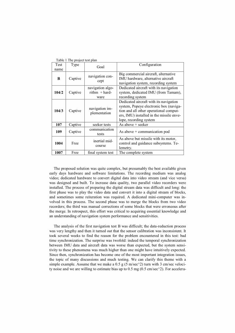
Table 1 The project test plan
Test
name
Type Goal
Configuration
B Captive navigation con-
cept
Big commercial aircraft, alternative
IMU hardware, alternative aircraft
navigation system, recording system
104/2 Captive
navigation algo-
rithm + hard-
ware
Dedicated aircraft with its navigation
system, dedicated IMU (from Tamam),
recording system
104/3 Captive navigation im-plementation
Dedicated aircraft with its navigation
system, Popeye electronic box (naviga-tion and all other operational comput-
ers, IMU) installed in the missile enve-
lope, recording system
107 Captive seeker tests As above + seeker
109 Captive communication
tests As above + communication pod
1004 Free inertial mid-
course
As above but missile with its motor,
control and guidance subsystems. Te-
lemetry.
1007 Free final system test The complete system
The proposed solution was quite complex, but presumably the best available given
early days hardware and software limitations. The recording medium was analog
video; dedicated hardware to convert digital data into video stream (and vice versa)
was designed and built. To increase data quality, two parallel video recorders were
installed. The process of preparing the digital stream data was difficult and long: the
first phase was to play the video data and convert it into a digital stream of blocks,
and sometimes some reiteration was required. A dedicated mini-computer was in-
volved in this process. The second phase was to merge the blocks from two video
recorders; the third was manual corrections of some blocks that were erroneous after
the merge. In retrospect, this effort was critical to acquiring essential knowledge and
an understanding of navigation system performance and sensitivities.
The analysis of the first navigation test B was difficult; the data-reduction process
was very lengthy and then it turned out that the sensor calibration was inconsistent. It
took several weeks to find the reason for the problem encountered in this test: bad
time synchronization. The surprise was twofold: indeed the temporal synchronization
between IMU data and aircraft data was worse than expected, but the system sensi-
tivity to these phenomena was much higher than one might have intuitively expected.
Since then, synchronization has become one of the most important integration issues,
the topic of many discussions and much testing. We can clarify this theme with a
simple example. Assume that we make a 0.5 g (5 m/sec^2) turn with 3 cm/sec veloci-
ty noise and we are willing to estimate bias up to 0.5 mg (0.5 cm/sec^2). For accelera-

tion of 0.5 g = 5 m/sec2, 1 msec of synchronization error will produce a measurement
error of 0.5 cm/sec, significantly less than the velocity error of 3 cm/sec. However,
after 1 sec, the bias error of 0.5 mg will cause a velocity error of 0.5 cm/sec, so the
same as the error due to miss-synchronization The observation was that the compari-
son of error due to miss-synchronization with velocity noise is misleading. The cor-
rect comparison is between the synchronization error and the error caused by bias that
we are willing to estimate. Indeed, these errors appear with similar correlation to the
trajectory. In this case, since we would like to keep the synchronization error well
below the error due to the estimated bias, the allowed synchronization error should be
on the order of 0.1 msec.
Test series 104/2 was less problematic; integration with the real IMU went smooth-
ly, and the performances and sensor calibration behaved well. This was a great oppor-
tunity to optimize the transfer alignment maneuver. The starting point was relatively
long S-shaped maneuver, required for a good estimation of the heading error and z-
axis drift. It turned out that in a Popeye-type missile, the sensitivity to heading error is
relatively low; the simple (albeit non-intuitive) explanation was as follows: if a mis-
sile is launched and does not perform any maneuvers, than at the end of the mission
its position error will be zero, even if the heading error was large (in this case all other
errors are assumed to be zero). In other words, heading error influences system error
only if there is acceleration. The most significant acceleration (due to the rocket mo-
tor) was at the beginning of the mission. This observation allowed to relax the re-
quirements for z-axis drift estimation and significantly reduced the need to estimate
heading error. As a result, a shorter maneuver was proposed which was much easier
from an operational point of view. It was based on a single, relatively small turn and
the time of captive flight was reduced significanly. An additional result of the 104/2
series was the tuning of the Kalman filter.
On Itzhack Bar-Itzhack, the first navigation group leader relates the following: "In
those days, Itzhack Bar-Itzhack was coming in to Rafael once a week to work with us.
For me, he was one of the team members, perhaps younger than many of the others.
He was always smiling, in a good mood and ready to tell new jokes, some of them not
necessary politically correct by today's standards. Nevertheless, from a professional
point of view, he was always serious, well-organized and very precise. He was always
ready to carry out new assignments, whatever was needed, once he had studied the
details of aircraft navigation systems in depth; on one occasion, for example, he pro-
posed a missile trajectory generator algorithm. We always discussed the current is-
sues, problems and plans with him."
The 104/3 tests, performed with the actual navigation system (hardware and soft-
ware), were relatively extensive; they aimed to cover the entire operational envelope.
The software integration was very successful; it worked well from the first flight test.
The most important lesson learnt here was the system's sensitivity to flight conditions:
for quiet flights very good results were obtained, whereas for low-level, fast flights,
the results were worse but still within requirements. The long-flight 104/3 test series,
followed by the even longer 107 series, was used to create a huge library of naviga-
tion data: real-life trajectories, sensor performance together with post-processing
analysis, and error sensitivities for a very broad family of error sources. This library,
which was continuously updated with new tests, served as an excellent platform to
learn navigation systems and develop new algorithms.
The seeker test series 107 showed a problem that appeared to be related to the nav-
igation system. The seeker pointing errors were too large. Rafael people claimed that
this phenomenon was due to aircraft navigation errors, whereas the air force claimed
that after position update the aircraft navigation error was about 50 m, and such large
pointing errors must therefore be related to the missile. The first task was to plan a
test that would separate the error sources. The idea was to keep the seeker tracking a
target at known positions, so the system pointing errors could be measured continu-
ously for several tens of seconds. A Kalman filter would be designed with measure-
ments of pointing errors and states of position error, attitude error (in an inertial refer-
ence frame) and misalignment between the seeker and the navigation system (related
to the body reference system). The Kalman filter implementation was off-line and
based on the already existing reconstruction infrastructure. This test showed with
high confidence that the pointing errors were due to position errors. Later analysis
showed that although the position updates were quite accurate, they did not properly
correct for the velocity error and therefore, after 1 min or more, the aircraft accuracy
was significantly worse than the specified 50 m. This fact endangered the entire pro-
ject, but a solution was proposed almost immediately. The initiative was to make
auxiliary target updates. The idea was to find, close to the actual target, an auxiliary
target with good visibility and known location. Then, from pointing to this target, the
system could estimate the pointing errors and correct them (assuming that they came
from horizontal position errors). This algorithm was accepted and applied in the sys-
tem. Years later, pilots still use this procedure with every aircraft working with GPS,
claiming that it improves performance; the reason for this is unknown, but my im-
pression is that this procedure survived the GPS era mainly because it makes the mis-
sion less boring. In any case, the lessons learned in line-of-sight analyses and the
integration with navigation errors were later used to propose installation of the navi-
gation system inside the seeker gimbal [9]. A well-known application of this approach
is Rafael's Litening Airborne Navigation and Targeting Pod.
The preparation for the first free flight test, test 1004, went according to plan, but
one day before the test, during the final captive flight test, a new feature was tested.
During the airframe configuration test, immediately after the launch, strong roll
movement was observed. Therefore, the pilot performed a strong roll movement (as
fast as he could) to simulate the release roll movement. As a result, in this route, large
navigation error appeared. It happened only once and there was a big debate whether
to stop the test launch or not. Rafael people (at least the senior ones) wanted to con-
tinue; it was the test pilot who persuaded the project managers (from the Ministry of
Defense) to postpone the test and require, from the Rafael team, a solid analysis of the
phenomena.
The result of the analysis was surprising: it was essentially a system/hardware
problem. It turned out that the actual maximal angular acceleration is much higher
than the one specified. Eventually the spec was changed, Tamam made the necessary
changes in their design and after several months of intensive work, test 1004 was
ready to restart. At the very end of the last test before the launch, an IMU error mes-
sage appeared. Again, long discussions, collection of all available data, consultations
with experts, lasted till late-night hours.
This time the decision was to continue the testing. On the following day, early in
the morning, the missile was launched. Before the successful happy ending, the mis-
sile was almost terminated by safety personnel due to a lengthy lack of communica-
tion with the operations room, first due to telemetry problems, then due to a tape-
recorder, that someone had put in the room and created acoustic noise oscillations. At
the very last moment the problems were fixed, and everyone in the operations room,
including the safety personnel, were able to witness the missile's precision in follow-
ing its designated route.
4 Post 1985: Still a Lot To Do
After the success of test 1004, the navigation group's involvement in the project
has gradually reduced. Then, in 1986, great excitement spread from the Popeye pro-
ject management: we were going to demonstrate the system in the United States. Pro-
ject management's view was that since the missile's development had been completed,
in order to reduce our costs and time schedule, the aircraft to be demonstrated in the
US should mimic the interface that was already integrated in the Popeye missile. At
this stage, schedule was very tight and intensive work was required: a few months for
implementations and integrations, then a few captive flights for testing and operation-
al training and finally, a full operational launch. In the course of the meetings and
tests, we understood that our system had excellent characteristics: the quality of the
seeker, the navigation accuracy and the very short and easy transfer alignment proce-
dure were world-class outstanding. From a technical point of view, the process ran
very smoothly with no critical failures. One improvement of note was the use of the
aircraft simulator to create dynamic trajectories, in order to record the blocks sent to
the Popeye and analyze them. In this way we were able to fix some problems well
ahead of the flight tests.
During the integration in the US, we understood that changing an aircraft's inter-
face to simulate another interface was an once-in-a-lifetime scenario and that the next
time we would need to change our interface. Then we understood that our design
lacks the flexibility to support such changes. The problem was related to Kalman
filter propagation and the time window for measurements. The first implementation
(due to a lack of spare computer resources) was very rigid; the covariance matrix was
propagated to a known a-priori measurement time, creating a narrow time window in
which the measurement should appear; if it didn't, the measurement was discarded
and the system was moved to the next second. In the next version of the transfer
alignment algorithms, due to the change in the covariance propagation scheme, the
system was ready to receive asynchronous measurements, with the only limitation
being the minimal time between measurements.
Another great challenge faced the team when it started work on the inertial naviga-
tion system for air-to-air missiles. It was clear that a dedicated maneuver for transfer
alignment was out of the question. The approach was to perform a continuous transfer
alignment, namely to turn on the missile navigation system before takeoff and keep it
working continuously such that the missile would be ready to launch all the time.
Since in every aircraft flight there are always periods of some acceleration, sensor
errors and pitch and roll angles can be estimated and kept accurate during the flight—
after intensive work for proper Kalman filter tuning of course. The only problem is
that for long flight periods with no accelerations, the heading error can grow. In an
air-to-air missile, due to its huge acceleration, the sensitivity to heading error is much
more severe than that in air-to-surface missiles. The solution came from a very inter-
esting direction: the reason that we could not perform a direct alignment (i.e. simply
copy aircraft orientation onto that of the missile) was that the missile had been in-
stalled under the wing, and its relative orientation was changing during the flight.
Indeed this was true, but only for pitch and roll; the heading misalignment (the differ-
ence between the aircraft and missile orientations) was almost fixed during the flight.
This observation led to adding another state to the Kalman filter, the new state being
the heading misalignment, and the resulting 13-state Kalman filter provided excellent
continuous transfer alignment. This 13-state Kalman filter has become a standard
solution that is implemented in all relevant airborne systems.
The stringent requirement for time synchronization between the aircraft and missile
has always been a key issue in aircraft integrations. The number of types of aircrafts
which needed to be integrated was constantly increasing, as was the number of Rafael
airborne systems that included navigation units. As a result, more and more cases of
an aircraft navigation system not providing the required synchronization accuracy
began to appear. The obvious consequence was performance degradation, until an
important observation was made. It was clear that precise synchronization is required
to accurately interpret the system errors during maneuvers. However, one could omit
the measurements during the maneuvers and estimate the system errors after a ma-
neuver had been completed. This non-trivial observation claimed that due to the inte-
gral nature of the system, there is no significant harm to performance when no meas-
urements are performed during the maneuver itself (but with enough measurements
after the maneuver) compared to the case in which all measurements are taken.

At this point our paper is complete; the basic solution for transfer alignment and its
essential improvements have been described. During those years, Rafael provided
state-of-the-art systems, with a constant line of improvements. Of course the real
story never ends, and the navigation group at Rafael continues to develop navigation
systems, based on the foundations described here, facing new challenges and produc-
ing new achievements.
In my opinion, the secret to accomplishment lies in following these three guide-
lines, as well illustrated in the story described herein:
Recruit capable people
Provide a challenge
Build an infrastructure and culture to analyze integrations and tests properly and in
depth
Acknowledgements
First I must thank Yaakov Oshman who encouraged me, from the very beginning, to
write this paper, and for his help and support which were vital in surmounting several
difficulties (for example, delays due to issues of security).
Then I must thank my colleagues from the navigation group who told me stories
from the different project phases, helped me formulate a complete picture, and pro-
vided helpful remarks. During these interviews and during the writing of this paper, I
must admit that Itzhack Bar-Itzhack's absence was painfully evident: I had so many
questions to ask him…
Lastly, and most importantly, I must acknowledge all of the people who worked on
this project: the project managers, the engineers: systems, software, hardware, control,
navigation and integration, the technicians, the Israeli Air Force flight test team, and
so many others whose coordinated work allowed everything to come together. For
me, they were simply wonderful people who I was lucky to work with and from
whom I learned a great deal.
References
[1] I. Bar Itzhack and E. Levinger, An analysis of errors in navigation inertial sys-
tems, Technion 1975 (in Hebrew).
[2] A. Gelb, Applied Optimal Estimation, The M.I.T. Press, 1974.

[3] I.Y. Bar-Itzhack and B. Porat, “Azimuth Observability Enhancement during In-
ertial Navigation System In-Flight-Alignment,” AIAA J. Guidance and Control,
Vol. 3, No. 4, pp. 337–344, July 1980.
[4] B. Porat and I. Y. Bar-Itzhack, “Effect of Acceleration Switching during INS
In-Flight-Alignment,” AIAA J. Guidance and Control, Vol. 4, No. 4, pp. 385–389,
July 1981.
[4a] A. Weinreb and I.Y. Bar-Bar-Itzhack, "The Psi Angle Error Equation in
Strapdown Inertial Navigation Systems," IEEE Transactions on Aerospace and Elec-
tronic Systems, Vol. AES-14, No. 3, May 1978.
[5] I.Y. Bar-Itzhack and Y. Vitek, "The Enigma of False Bias Detection in a
Strapdown System during T.A," AIAA J. of Guidance March-April 1985
[6] D. Goshen Meskin and I.Y. Bar Itzhack, "Unified Approach to Inertial Naviga-
tion System Error Modeling," Vol. 15, No. 3, pp. 648–653, 1992.
[7] D. Goshen Meskin and I.Y. Bar Itzhack, "Observability Analysis of Piece Wise
Constant Systems, Part I – Theory," IEEE Transactions of Aerospace and Electronic
Systems, Vol. AES-28, No. 4, pp. 1056–1067, October 1992.
[8] D. Goshen Meskin and I.Y. Bar Itzhack, "Observability Analysis of Piece Wise
Constant Systems, Part II – Application to Inertial Navigation In-flight Alignment,"
IEEE Transactions of Aerospace and Electronic Systems, Vol. AES-28, No. 4, pp.
1068–1075, October 1992.
[9] Z. Berman, "On Range and Attitude Estimation," Proceedings of the IEEE Po-
sition, Location and Navigation Symposium, Las Vegas, 1994.
[10] J. Reiner, "In-Flight Transfer Alignment Using Aircraft-to-Wing Stiff Angle
Estimation," AIAA Conference on GNC, San Diego, CA, July 1996.
[11] J. Reiner, J. Ben-Jaacov and H. Rotstein, "Transfer Alignment in the Presence
of Unknown Aircraft Measurement Delays," IBA Conference on Navigation, Her-
zelia, Israel, May 1999.
[12] I.Y. Bar Itzhack, "In Flight Alignments of Inertial Navigation Systems," Se-
ries of Control and Dynamic Systems, Vol. 38, pp. 369–396, 1990.
[13] D. H. Titterton and J. L. Weston, Strapdown Inertial Navigation Technology,
Peter Peregrinus Ltd., UK., 1997.