the earthscope facility - global positioning system · pbo plate boundary observatory ... stanford...
TRANSCRIPT

1
The EarthScope Facility: A new experiment in cooperative
solid earth science
Will Prescott, UNAVCO, Inc.
CORS Forum
CGSIC 42nd Meeting
8-9 September 2003
Portland, Oregon

2
Objectives of Presentation
• Provide an overview of EarthScope
• Provide more detail about PBO
• In the process, I hope you will see that:
– We need good monuments where ever possible
(i.e. in CORS when possible)
– We need assistance in permitting
– We need assistance in recruiting

3
A New View
into Earth
A Science and Facilities Program
for study of the structure,
dynamics and evolution
of the North American continent

4
USArray US Seismic Array
Integrated system of seismic arrays to provide a coherent 3-D image of the
lithosphere and deeper Earth
PBO Plate Boundary Observatory
Arrays of strainmeters and GPS receivers to measure real-time deformation
on a plate boundary scale
InSAR Interferometric Synthetic Aperture Radar
Images of tectonically active regions providing spatially continuous strain
measurements over wide geographic areas.
SAFOD San Andreas Fault Observatory at Depth
A borehole observatory across the San Andreas Fault to directly measure the
physical conditions under which earthquakes occur
EarthScope Components
5
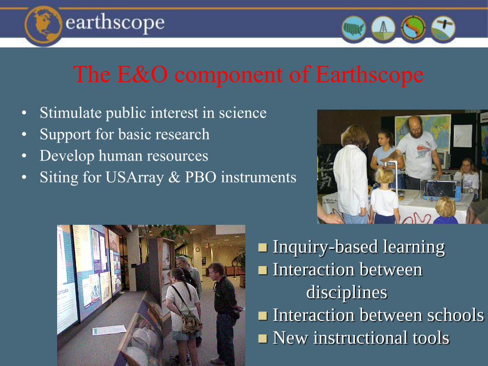
The E&O component of Earthscope
• Stimulate public interest in science
• Support for basic research
• Develop human resources
• Siting for USArray & PBO instruments
Inquiry-based learning
Interaction between
disciplines
Interaction between schools
New instructional tools

6
EarthScope Science Goals
• Structure and evolution of the continent
• Earthquake processes and seismic hazards
• Magmatic processes and volcanic hazards
• Active deformation and tectonics
• Continental geodynamics
• Fluids in the crust
• Exploration and Discovery
7
Data Policy
• PBO GPS data, Big Foot seismic data
– Completely open data policy
– Immediate unrestricted access to all data
• Portable GPS
– Open data policy (unless community rebels)
• Flexible Pool seismometers, SAFOD experiments
– Data subject to a period of exclusive use, if funding agency
concurs with Investigator’s request
8
EarthScope Planning
• 1992 - 1996
• Concept development
PBO, Array USA, InSAR
San Andreas Fault Zone Drilling
• 1997 - 1998
• Discussions with NSF
• Workshops and Steering Committees
• 1999
• EarthScope integration
• ES Working Group established
• Nat. Science Board Approval
• 2000• FY01 NSF Budget
– Not funded by Congress
• 2001• Program Plan
• NRC EarthScope review
• NRC BROES report
• FY02 NSF Budget
– No new starts
• 2002• E&O Workshop
• Canada/Mexico/US discussions
• Ocean Mantle Dynamics WS
• EarthScope in FY03 request

9
EarthScope Project
Plan EarthScope Science
Workshop
USArray and PBO Workshops
Education and Outreach
Program Plan
EarthScope Planning Documents

10
Special Panel to review EarthScope
Integrated Science, NRC, 2001
The Committee concludes
that the scientific rationale for
EarthScope is sound,
that the scientific questions to be
addressed are of significant
importance, and
that no necessary components
have been omitted.
The Committee recommends
that all four EarthScope
components be implemented as
rapidly as possible.”

11
EarthScope - Current Status• The FY 2003 funding has been approved for the National Science
Foundation to initiate construction of EarthScope: USArray, San Andreas
Fault Observatory at Depth (SAFOD), and Plate Boundary Observatory
(PBO) at $30.0 million.
• An MREFC proposal was submitted by IRIS, Inc., UNAVCO, Inc. and
Stanford University to initiate construction of the first 3 components of the
EarthScope facility.
• The proposal has received approval at all levels of NSF. We are waiting on
final signatures on Cooperative Agreements.
• We anticipate a start date of 1 September 2003, with funding shortly
thereafter.
• Funding is still being sought for InSAR.
• The expected operational lifespan of EarthScope is 15 years

12
EarthScope Facilities Executive Committee
• Greg van der Vink EarthScope Facility Project Director
• David Simpson IRIS Consortium President, PI-USArray
• William Prescott UNAVCO Consortium President, PI-PBO
• Mark Zoback Stanford, PI-SAFOD
• Goran Ekstrom Harvard, Chair, IRIS Board
• Steve Hickman USGS, Co-PI SAFOD
• Paul Silver Carnegie, UNAVCO Board

13
Challenges Ahead• Install, evolve and maintain the core MREFC facility
• Develop and Integrate:
Education & Outreach
Information Technology
and Get InSAR funded!
• Engage the next generation of Earth Scientists
www.EarthScope.org

14
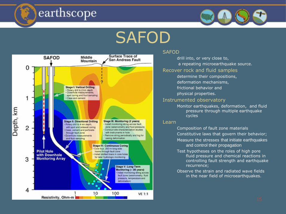
SAFOD
Drill 4 km into zone of microearthquakes at the nucleation point of the 1966 Parkfield M 6 earthquake
15
SAFODSAFOD
drill into, or very close to,
a repeating microearthquake source.
Recover rock and fluid samples
determine their compositions,
deformation mechanisms,
frictional behavior and
physical properties.
Instrumented observatory
Monitor earthquakes, deformation, and fluid pressure through multiple earthquake cycles
Learn
Composition of fault zone materials
Constitutive laws that govern their behavior;
Measure the stresses that initiate earthquakes
and control their propagation
Test hypotheses on the roles of high pore fluid pressure and chemical reactions in controlling fault strength and earthquake recurrence;
Observe the strain and radiated wave fields in the near field of microearthquakes.
16
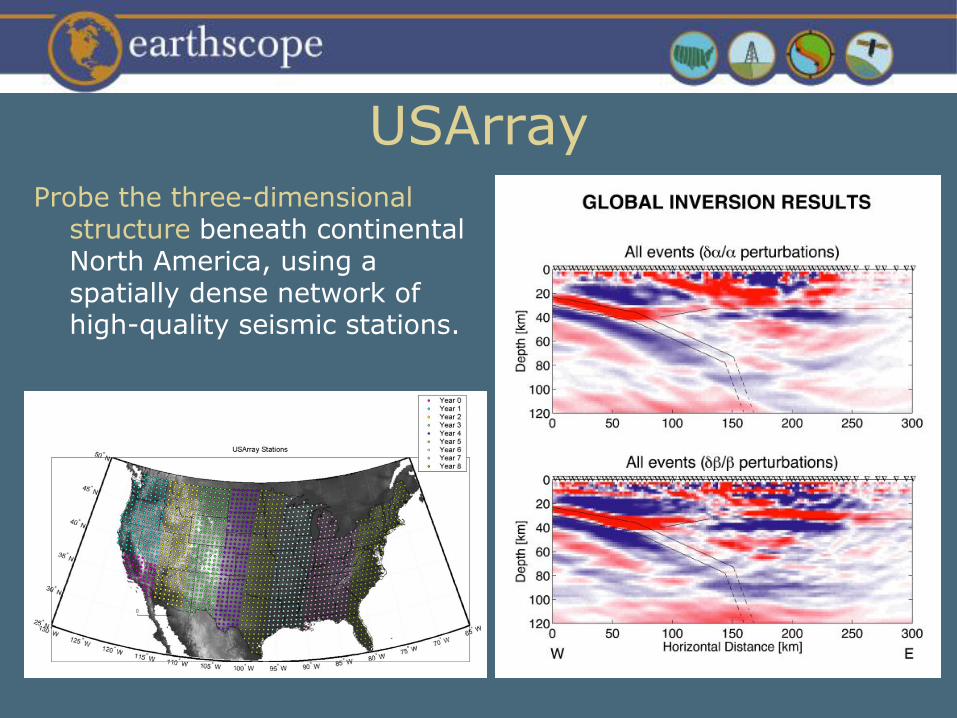
USArrayProbe the three-dimensional
structure beneath continental North America, using a spatially dense network of high-quality seismic stations.
17
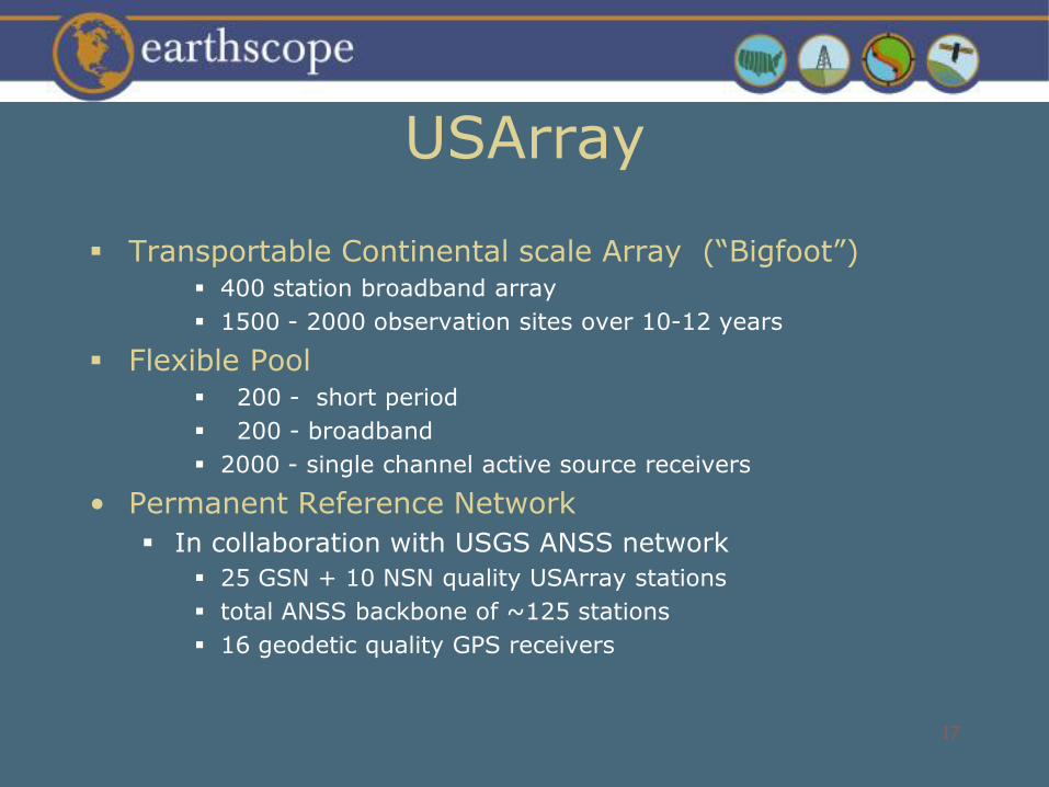
USArray
Transportable Continental scale Array (“Bigfoot”) 400 station broadband array
1500 - 2000 observation sites over 10-12 years
Flexible Pool 200 - short period
200 - broadband
2000 - single channel active source receivers
• Permanent Reference Network
In collaboration with USGS ANSS network
25 GSN + 10 NSN quality USArray stations
total ANSS backbone of ~125 stations
16 geodetic quality GPS receivers

18
Plate Boundary ObservatoryDesigned to study the three-dimensional strain
field resulting from plate-tectonic deformation
of the western portion of the continent

19
Plate Boundary Observatory
• Focused, dense deployments of GPS and strain
• 775 continuous Global Positioning Systems
• 175 borehole strainmeters
• 5 long baseline strain components
• Backbone network of GPS stations
• 100 sites to provide a long-wavelength, long-period synoptic view of the entire plate boundary zone
• Receiver spacing will be approximately 200 km
• Portable GPS receivers
• Pool of 100 portable GPS receivers for temporary deployments to areas not sufficiently covered by continuous GPS
• Geo-PBO
• Image acquisition
• Image archive
• Enhanced dating laboratories

20

21
PBO Science/Directions• Science Goals
– What are the forces that drive plate-boundary deformation?
– What determines the spatial distribution plate-boundary deformation?
– How has plate-boundary deformation evolved?
– What controls the space-time pattern of earthquake occurrence?
– How do earthquakes nucleate?
– What are the dynamics of magma rise, intrusion, and eruption?
– How can we reduce the hazards of earthquakes and volcanic eruptions?
• Choice in Instrumentation– Capture signals with periods ranging from seconds to decades
• Deployment Strategy
• Role of Geological Component
22
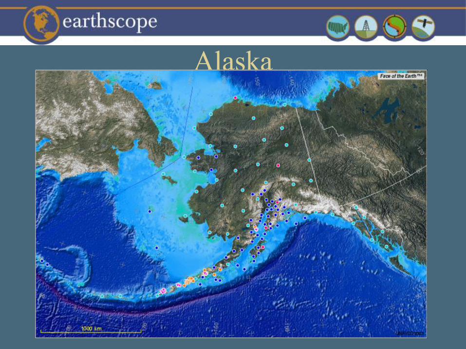
Alaska

23
Existing
W. US
Only includes networks installed for geophysical research. Includes some but not all CORS.

24
Existing
W. US
+ New

25
Existing
California
Only includes networks installed for geophysical research. Includes some but not all CORS.

26
Existing
California
+ New
27
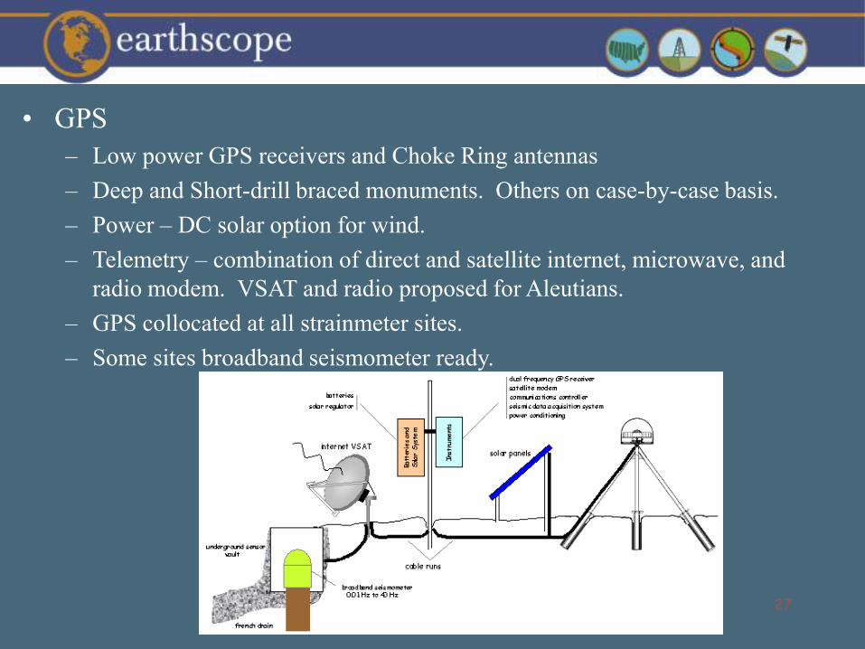
• GPS
– Low power GPS receivers and Choke Ring antennas
– Deep and Short-drill braced monuments. Others on case-by-case basis.
– Power – DC solar option for wind.
– Telemetry – combination of direct and satellite internet, microwave, and
radio modem. VSAT and radio proposed for Aleutians.
– GPS collocated at all strainmeter sites.
– Some sites broadband seismometer ready.

28
• Strainmeters
– Borehole systems a
combination of Sacks-Evertsen
dilatometers and Gladwin
Tensor Strain instruments
installed in cluster of 4 or 5.
– Borehole systems have 3-
component, 2-Hz, borehole
seismometer possible upgrade
to 3-component broadband
sensor.
– Borehole systems have
tiltmeter, GPS, pore pressure &
heat flow monitors
– GPS collocated at all
strainmeter sites.
– Propose using contract drilling
managed by DOSECC
29
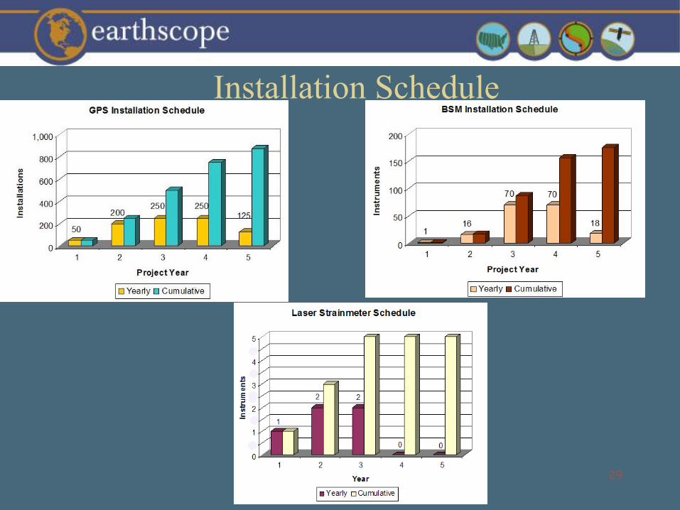
Installation Schedule
30
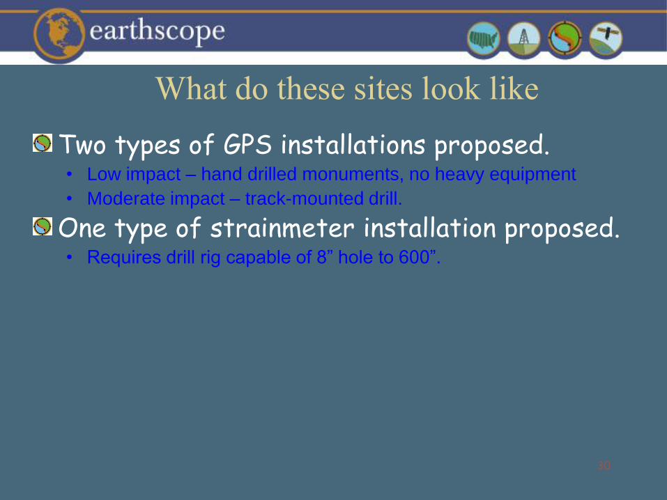
Two types of GPS installations proposed. • Low impact – hand drilled monuments, no heavy equipment
• Moderate impact – track-mounted drill.
One type of strainmeter installation proposed.• Requires drill rig capable of 8” hole to 600”.
What do these sites look like

31
Monument drilling
Monument installation
Final site
Moderate impact GPS
32
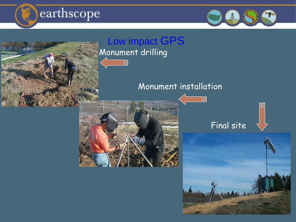
Monument drilling
Monument installation
Final site
Low impact GPS

33
Borehole drilling
Strainmeter installation
Final site
Strainmeter

34
Operations Management
• Operations Manager
oversees
– 6 regional engineers, jr.
engineers, and data techs.
– 2 strainmeter engineers
– Backbone engineer
– Campaign engineer and
tech
– Permit coordinator
35
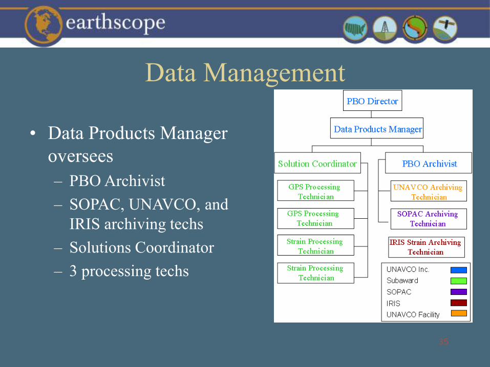
Data Management
• Data Products Manager
oversees
– PBO Archivist
– SOPAC, UNAVCO, and
IRIS archiving techs
– Solutions Coordinator
– 3 processing techs
36
Concluding Remarks
• For geophysical research, marks must be stable at the < 1 mm level for decades.
– Requires good monuments, few antenna changes, good records on changes.
• To install ~1000 new geodetic stations over next five years will require help with:
– Permitting – http://www.unavco.net/public/recon/submitinfo.aspx
– People – http://www.unavco.net/public/careers/searchjobs.asp
• http://www.unavco.org
37
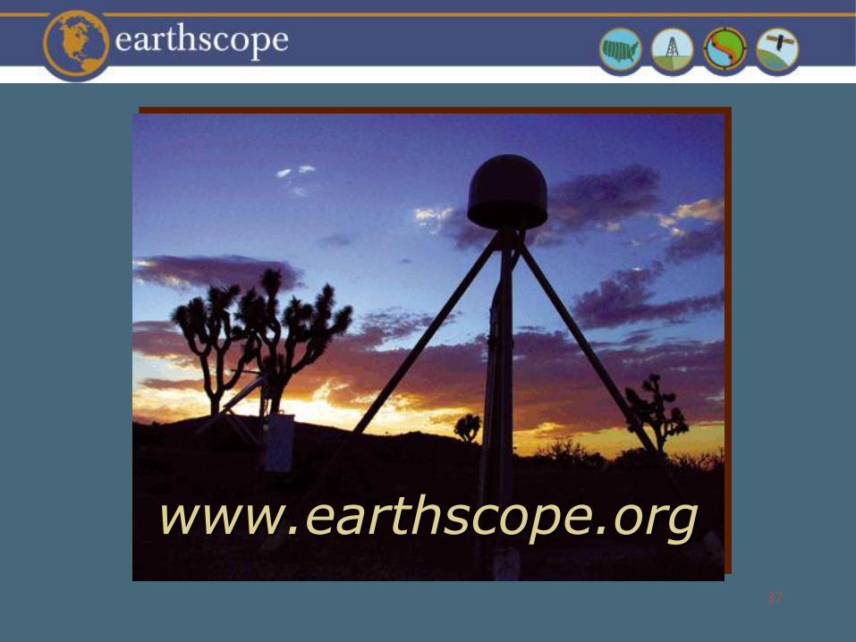
www.earthscope.org