the effect of carbonationon creep
TRANSCRIPT

THE EFFECT OF CARBONATIONON CREEP
AND SHRINK..l\.GE OF PORTLAND CEMENTCONCRETE
by
FRANCISCO ORLANDOMARTIN ALVAREZB.S.C.E., University of Puerto Rico
(1960)
SUBMITTED IN PARTIAL FULFILLMENT
OF THE REQUIREHENTS FOR THE
DEGREE OF 1v1ASTEROF SCIENCE
at the
:MASSAClIDSETTSINSTITUTE OF TECHNOLOGY
Signature of Author ;~~~~;. i~.~~ii~i~~·~~~i~~~~i~~.~{ ~~~~t~~t~~Department of Civil and. Sanitary Engineering
May 20, 1961
Certified. by •••.•••••••••••••••••••• 1./ •••••••• ~~-" •••••••••• 7;( .Thesis S~pervisor
Accepted by •••••••••••••••••• '. "7'- .~. /'/' T~ ('...r...<~~L-Cr/JI! .~'. · · .. · ... ·ChcU.rman, Depa ~ta1 Conuni ttee
Grasluate Students

DEDICATION
To Mr. Hermand E. :rvlonserrate: for
his ins~iration and guidance.
2.

ABSTRACT
THE EFFECT OF CARBONATION ON CREEPAND SHRINKAGE OF PORTLAND CENENT CONCRETE
by
Francisco Orlando Martin Alvarez
Submitted to the Course in Building Engineering and Constructionof the Department of Civil and Sanitary Engineering on May 20, 1961in partial fulfillment of the requirements for the degree of Masterof Science.
The present study consists of determining hO\-T the creepand shrinkage of' concrete is aff'ected by various amounts of C02 andmoisture in the surrounding atmosphere. Both loaded and.unloadedspecimens \.rerestored in controlled humidities of 33, 52, 76, and97 percent. Four different percentages of C02 l-Tereassociated'vith each relative humidity: 0, .03, 50, and 100 percent, givinga total of 16 different storage conditions.
The data collected indicated that the carbonation shrinkagetends to be higher in atmospheres containing higher percentage ofcarbonic gas. The effect of humidity on carbonation tended to beextremely important, with 52 percent relative humidity producingthe highest carbonation shrinkage. In addition, it ,.,asfound thatthe rate of carbonation was highest during the earliest stages ofthe carbonation process.
An attempt was made to measure the influence of carbonationon creep. No conclusive evidence ,{as found that carbonation reducescreep. The results shot-redthat carbonation shrinkage of the loadedspecimens was slightly 10\{er due to partly closing of the poresunder load.
The collected data is portrayed graphically as well as intabular form, photographs of the pertinent apparatus are included toillustrate experimental techniques. Detailed information concerningthe general testing methods is presented..
Thesis Supervisor: J. Lloyd. Cutcliffe
Title: Instructor
3.

ACKNOHLEDGMENT
The author wishes to express his gratitude to Instructor
John Lloyd Cutcliffe for introducing him to and stimulating his
interest in this subject.The author is deeply grateful to IvIr. Albert J. 0 t Neill,
Technical Instructor; to v~. Joseph E. vfuite of the Building Materials
Laboratory; Mr. Donald Gunn of' the structural Ana.lysis Laboratory; and
~rr. James E. King of the Plastics Research Laboratory for their in-
dispensable help in the technical aspects of the testing procedure.
The author would like to acknowledge Messrs. Roger Curran,
James Burtlich, r.fa.rioSerani, and Harold Levy ,,,hodirectly or
indirectly helped in the preparation of this work.
Finally, to Miss IvIarionCurley for typing the manuscript.
4.

Chapter
I
II
III
IV •
TABIE OF CONTENTS
INTRODUCTION
~neral Concrete ConstructionConcrete Behavior
PREVIOUS AND PRESE:NT HORK ON CARBONATION •
Nature of CarbonationPrevious Work on CarbonationThe Present Work
RESULTS .
DISCUSSION OF RESULTS
Photographic DataAbsorption Curves for 50% C02Rate of CarbonationLength and 'Height Changes atDifferent Relative Humidities
RECOMMENDATIONS
CONCI1JSIONS
APPENDIX A
APPENDIX B
BIBLIOGRAPHY
page
10
1011
20
20
21262943
434445
46
48
495163
72
5.

LIST OF FIGURES
Figure page
1 Creep vs. Time 192 Shrinkage vs. Time 193 Qualitative Depth of Carbonation 444 Compression Machine and
Loading Frame 675 CO2 Free Atmosphere Control . 686 Normal Air Atmosphere Control 697 100 Percent CO2 Atmosphere Control 708 50 Percent CO2 Atmosphere Control . 71
6.

LIST OF TABLES
Table page
I Length and Weight Change at0% CO2 Concentration 32II Length and 'Height Change at
.03% CO2 Concentration 34III Length and Weight Change at50% CO2 Concentration 36rl Length and Weight Change at
100% CO2 Concentration 38V Carbonation Vs. Time 40
VI Rates of Carbonation vs. Time 42
7.

LIST OF GRAPHS
Graph page
I Effect of Relative Humidity on CarbonationShrinkage and Creep at ~~ CO2 33
II Effect of Relative Humid.ity on CarbonationShrinkage and Creep at .03% CO2 35
III Effect of Relative Humidity on CarbonationShrinkage and Creep at 50% CO2 37
Dl Effect of Relative Humidity on CarbonationShrinkage and.Creep at 10()o~ CO2 39
V Carbonation vs. Time for50% CO2 Concentration' 41
VI Rate of Carbonation vs. Timefor 50% CO2 Concentration 43
8.

Photograph
1
2
3
4
5
6
7
8
9
10
11
12
13
14
151617
LIST OF PHarOORAPHS
Depth of Carbonation of SamplesExposed to 33% R.H.
Depth of Carbonation of SamplesExposed to 52!/0 R.H.
Depth of Carbonation of SamplesExposed to 76% R.H.
Depth of Carbonation of SamplesExposed to 97% R.H.
Specimens and Mold
Measuring Sample in the Up-Right Gage
Weighing of Samples
Stabilization of Samples •
Loaded and Unloaded Specimens in Jars
Measuring Sample on Loading Frame •
Hydraulic Compression Machineand Loading Frame
Measuring Spring Deformation
Carbonation with Zero Percent CO2at Different Relative Humidities
Carbonation with .03 and 100 PercentCO2 at Different Relative Humidities •
Carbonation with 50% CO2 •
Measuring Relative Humidity .
Loading Frame and Sample •
page
30
30
31
3154
54
54
56
56
57
58
58
60
60616164
9.
INTRODUCTION
General Concrete Construction
Concrete is a mixture of' inert materials of varying sizes,
which are bound together with a cement paste. The whole mass is
deposited in a plastic or fluid state; and, almost immediately after
placing, a hardening process start which, under the proper curing
conditions, may continue for years. Because it is placed in a
plastic condition, concrete lends itself successfully to all kinds
of construction; provided suitable molds are used or special placing
equipment is available, such as a tremie (1) for underwater work
placing.
Concrete possesses certain characteristics that have been
responsible for its great demand as a building material. Since con-
crete is a physically amorphous material (after mixing) it can be
easily handled in common types of jobs as well as being adaptable
to complex shapes. This material provides excellent strength for
structural uses. High strength developed by modern concretes enables
the designer to employ various methods of design, e.g., prestressed
concrete design. Although it is a high strength material, it has a
relatively low cost; one of the many reasons why it has been used
extensively.
Durability, low maintenance cost, fire resistance are but
a few of the practical qualities responsible for its broad acceptance
as a major construction material. In addition to the practicability
10.

of' the material, structures of concrete exhibit manyaesthetic
qualities.
Concrete Behavior
A structural unit maybe considered a failure whenthe
purpose f'or which it was designed is unaccornplished. Failures can
be divided into two general categories. These are: First, whenthe
structure completely or partially collapses due to gravitational,
earthquake, wind, as well as yielding of the supports. Second, when
the structure can still hold the imposedloads but deflections and
cracks makeit unsuitable to accomplish the purpose for which it was
designed. Both types of' f'ailure are directly related to the stresses
in the concrete set up by the loads and volumechanges, such as,
thermal contraction and expansion, shrinkage and creep.
The effect of' loads on structures has been extensively
investigated by a large numberof authors as to different types of
loading techniques as to determine the behavior of the concrete
structures. Laboratory test sa.m:plesas well as completed units have
been load tested to determine the different stress patterns set up
by these forces.
Temperature ef'fects (2) have been the cause of failure of a
great manynumberof structures. These effects have also been studied
to detennine the mechanismof expansion and contraction on concrete.
The results of the aforesaid studies have been applied to a large num-
ber of commercial thermal expansion joints to prevent these failures.
11.
12.
Most of the previous work on thermal changes of concrete
has determined that temperature changes mayoccur at any time and
continue indefinitely or significant temperature changes mayoccur
over short periods and maybe repeated frequently. (3) Other factors
that are connected with temperature changes in length:
(1) Magnitude of the change
(2) Rate of change and distribution
(3) Coefficient of expansion of the concrete
(4) Modulusof elasticity of the concrete
(5) The degree of restraint
(6) Coefficient of expansion of the
reinforcement and aggregates
(7) Type of cenent
Concretes under load tend to creep and shrink. Creep or
plastic flow is defined as increased deformation with time at constant
load. Shrinkage is usually associated with a change in length due
to water loss of the member. Under ordinary conditions shrinkage and
creep have the same direction even though they mayhave different
magnitudes.
Plastic flow or creep is due largely to the seepage of water
from the gel whenan external load is applied to the concrete. The
flow of water to or from the cement gel takes place through minute gel
pores. The flow through the gel pores is a function of the pressure
gradient" thus resulting in a more rapid expulsion of water. Powers(4)

13.
has explained this as an entropy effect. The rate of expulsion is
also a function of the vapor pressure on the outside of the mass.
Shrinkage caused by the loss of moisture, as well as time yield due
to seepage, are interrelated phenomena,although they maybe con-
veniently considered as separate and additive in their effects.
Davis(5) suggested that differences in flow observed in
concrete containing different mineral aggregates may be due to
crystalline flow. He also suggested that the existence of lateral
flow, accompanyingaxial flow whenthe lateral dimensions are unre-
strained, maybe caused by viscous flow.
Presently there are manytheories related to this phenomena
and someare extensions , with external stress introduced as a variable,
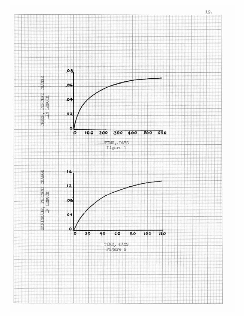
of shrinkage. A typical curve is shownin Figure (1) for a concrete
in compressionunder a load of 600 poundsper square inch. Fromthis
figure the creep is seen to occur rapidly, in the first few weeks after
loading and then to proceed at a steadily diminishing rate. The creep
is directly proportional to the applied stress up to a high proportion
of the strength and this holds even downto the smallest loads for
which measurementsare practicable.
Davis found that the higher the sustained stress, the greater
the flow. The moisture content of the cementgel has a markedeffect
upon the time yield; the flow of a totally dry concrete being of small
magnitude. The extent of hydration of the cementalters the time vs.
flow relation appreciably, since concrete of greater age under given
curing conditions at the time of loading showsless plastic flow. In

14.
plain concrete flow has been observed to continue even after almost
7 years under sustained stress ~ although the rate of flow is very
small at such ages. Usually the flow practically ceased after 1 or
2 years.
Ostlund(6) has developed mathematical expressions taking
into consideration various factors; viz.~ the magnitude of the stress,
the time which has elapsed since the load was applied~ the age of the
concrete whenthe load was applied~ the dimensions of the test body~
the composition of the concrete, the atmosphere around the sample~
the componentsof the concrete and so on. It is knownfrom experiments
that creep~ as well as the rate of creep~ increases whenthe atmosphere
around the test body becomesdrier. Also the rate of creel' decreases
with increasing dimensions of the test body.
Small plain concrete cylinders stored in dry air under
sustained stress (within the range of ordinary working stresses for
concrete) mayhave a total change in length, due to flow and shrinkage
combined~equivalent to 1 or 2 inches per 100 feet in 7 years. For
cylinders stored under moisture conditions, the total deformation due
to flow and expansion maybe only one-fourth to one-third of the total
deformation of similar concretes stored in dry air.
Davis found the total unit time deformation of air-stored
reinforced concrete columns to be from one-third to one-half of those
in corresponding air-stored plain concrete columns. These deformations
cause awreciable changes in the distribution of stress between the

steel and concrete in reinf'orced concrete columnsunder load in dry
air. Under such deformations the stress in the steel is increased.
washa(7) reported on plastic flow of thin rein:f'orced con-
crete slabs of' a given span, water cement ratio and curing method.
The greatest creep def'lections were obtained for the slabs madewith
the largest water content. This result was most pronouncedf'or the
longest span, and least pronouncedfor the shortest span. Somebeams
were sealed by painting themwith Bakelite lacquer and then with
para:f':fin. Plastic :flow, shrinkage, warpageand weight loss all took
15.
place at a slower rate for the sealed beamsthan :for the dry (unsealed)
specimens. The ultimate shrinkage and weight loss were about the same
for the two curing conditions, but the sealed specimenshad higher
modulusof elasticity and ultimate compressive strengths at 5 years.
The sealed specimensgenerally had lower plastic :flowdeflections.
and deformations.
Shrinkage has generally been attributed simply to water loss
of the mass but present evidence indicates the exact mechanismof
shrinkage is :far more complicated than this explanation indicates.
Sometheories related to the capillary structure of the material and
the nature of' the binding agent postulate such things as capillary
tension, surface sorption, swelling pressure of' a gel and interlayer
of crystals as possible explanation of shrinkage. The capillary
tension theory(8) shrinkage is associated with the increase of the
tension at the water meniscus in the capillaries as drying proceeds.
The theory is based on Kelvin's equation that there is a certain
16.
radius of curvature of a water meniscus that corresponds to a given
reduction in vapor pressure. As water recedes in the capillaries this
curvature increases and the tension forces produce a tension in the
water remaining in the capillary pores. This liquid tension must be
balanced by an equivalent compressivestress in the solid producing
shrinkage deformation. Whenwater is taken up the meniscus advances
up the capillary, the radius of curvature decreases and finally
vanishes whenfree water is present at the surface. During this
process the liquid tension and induced compressivestress and shrinkage
lessen and finally disappear. The surface sorption theories are asso-
ciated with the cementgel itself since it is here that the greak bulk
of the surface area lies. Wehave seen from former investigators
that the gel can absorb water and that the amountof it held in films
on the internal surface dependson the vapor pressure. This film of
water is held between the particles of the gel; the thickness of the
film determining the separation of the particles. Therefore shrinkage
will be suspected. The swelling pressure of the gel theory takes into
consideration that cementsets in the fully saturated condition with
its gel fully expanded. As it dries and water leaves the gel, nega-
tive pressures or tensions will be set up inside it. The resulting
contraction is resisted by the rigid frameworkof the mass, which is
thus put into tension. This internal tension could be called the
cause of shrinkage. The interlayer of crystals theory takes into con-
sideration changes in the lattice spacing of the hydrated calci~
silicate crystals with their water content. These crystals have a

17.
layer structure and water molecules can enter between layers expanding
thus the lattice. Evidence of' a similar ef'f'ect with hydrated calcium
tetra-aluminate has also been f'oundby an overall movementof' the
solid. This accounts f'or somedimensional changes in concrete.
No conclusion can be drawn f'romthese shrinkage mechanisms
but it seems that capillary ef'f'ects mayoperate at high relative
humidities, e.g., 70-80 percent and above; gel sorption at inter-
mediate humidities and the lattice shrinkage of' hydrated calcium
silicate at low humidities. It must be noted that whenset cement
or concrete loses water, the change in volumeis only a small f'rac-
tion of' the volumeof' the water lost. A typical shrinkage curve is
shownin Figure (2) at constant atmosphere conditions.
The f'ollowing are the most important factors that influence
drying shrinkage: (9) (10)(11) the water cement ratio of' the paste, the
composition and fineness of' the cement, the amountof' paste in the
concrete, the characteristics and amountof' admixtures used, the mix
proportions, the mineral composition of' the aggregates, the maximum
size of' aggregates, the size and shape of the concrete mass, the amount
and distribution of reinforcement, the curing conditions, the length
of' the drying period, the humidity of' the surrounding air, cement and
water content, gradation of aggregates, age at f'irst observation,
duration of test and absorptiveness of f'orm. These factors are also
associated with the phenomenonof creep. This association is why
someauthors have described creep as a special case of' shrinkage under
load.

All of the previously mentioned factors have a definite
bearing on the problem of shrinkage and creep. There are some other
problems that have not been studied which may have a definite bearing
on creep. The purpose of this study consists of determining the
effect of different carbonic gas concentrations on shrinkage while
at the same time extending such investigation to creep flow.
18.
19 .
+
I
-+- •-T"- +
t' +- •• t -t
. + ~p:T t+ : ::-;.t+
++.-!- +t-t-+-+-H+ .~;:t
---rl+
... -
- ..:.' ;
.. -+
. : : H-: : .' .: .. ;"';'
.. ' , ,
. : +- ' .,;. : -T: ."- ~. !. -.: I, . ~ .. : _.. t. . " t-- - .. +-
. • ' - I-H- t- , .. t+++ -j--I--' .... , -+-, .. " rHI. rl=h=""";"': -, +: ~-t-:h . .:.:m
. t--l-
.
.
.
:"H -+, ., ..
. I-- ,.. ,.
, ..... -
.,-': :::, . : .. :
• :- -: .: : --+
~." .- .. ,
. - -
,
:
.,.- - ,
.+... .. .
..
.~. +t
I+-+- :t
+-V ' ~ :i-.-.:r I.
. i--,.-. ~".. -+-r-+--- ~,. I-
, .Ii.: .. -~:
-T"
.....
... ~
.-f
. -
,
+r'''''' +
_.1":' '.-,
.
. :
.,-
, ' .
: +,,: _.::: .~I' +- ,;-- -, : .<+::;-. ;':1-+--' =-.:...... :;:- '+-T
.
,
, ,
., ,
, , ..... - ,
-
:. ,...-
. '
. . . -
.
1-: .-4..
4-+
.;- '-t 't-r~1if~,+
.
. :' :
+r-+ '..J..4 -r' +
.-;'# 1- -.,-
__ I+--+
++ -,. I-+-+-. ~+tt +, h- +++-H. 1-t- + 1--~. +-+ H j-+-1.+ =.:::::-: ~~:- ~-tt.+-t:::+=+: +-r-.--
i; -+-,+-; :--r+-r --r-+-j-t- +t++ ~ ~ .- t++-+- +-+--r-t- -+-;.,.. + ++ -r:;=r -r+-+ - H +-
t +
. -.
.: ,.: - - ,
, .
,- '. -:
,
, .
.
..... T ~ .' ~
. +-:1 --t:h'+':
,
,
:.....
. : .. :. ':.:: ....
.- : I~:.+ :-.
.+++ +-

II. PREVIOUSANDPRESENTWORKONCARBONATION
Nature of' Carbonation
It has long been accepted that carbonic gas has an effect
on concrete, but information on the nature and extent of' this ef'f'ect
is meager. Bef'ore carbonation is treated as such it is desirable to
have in mind someimportant facts. It is beyond the scope of this
work to discuss the principles upon which the theories of cement
hydration rest; but it is imperati ve to know:fromwhere the compound.s
involved in carbonation are available.
In the hydration process of' Portland cement it is well
agreed that "tricalcium aluminate reacts extremely rapidly and the
tetracalcium aluminoferrite very quickly."* Attack of tricalcium
silicate soon leads to saturation of the solution with lime due to
hydrolysis. In a very short time calcium hydroxide crystals can
develop in the hydrating mass, together with the usual structure
less hydrated silicates. The amountof' free calcium hydroxide in
the concrete mass could be altered by additions or combinations with
such materials as pozzolans. The air mixture surrounding the concrete
contains carbon dioxide as one of its constituents. Therefore, this
gas is available in concentrations of' approximately .03 per cent
(.0003 atmosphere).
*Chemistry of Cementand Concrete, Lea and Desch, 1955, p. 205.
20.

2l.
Toennies(l2) has defined carbonation as the chemical com-
bining of carbon dioxide and the hydration product of portland cement.
The primary importance in this chemical reaction is the combination
of calcium hydroxide with carbonic gas, in the presence of water, to
yield calcium carbonate and more water, e.g.
In the case of lime plasters and mortars voss(l3) considers
that this reaction still follows through in some cases and in the
presence of excess CO2 the following reaction takes place:
This new compound tends to close small fissures and cracks;
thus the term autogenous healing has been coined.
Al though there exist experimental evidence that substantially
all of the constituents of cement are subject to ultimate carbonation
under ideal conditions, the author considers that under ordinary
service conditions of the material the most important reason is the
combination of free lime (Ca(OH)2) with carbonic gas (C02).
The work of BeSSey(l4) shows some light in higher lime
content mixes of cement
Previous Works on Carbonation
A great many investigators have realized that the combina-
tion of carbon dioxide with the cement components is a practical and

important problem. Some of these men will be mentioned at this
stage of this report.
Shiedeler(15) realized that carbonation of masonry units
is accompanied by their linear shrinkage. He also found that the
moisture condition of the masonry unit has had an influence on their
receptiveness • Units predried to a moisture condition in equilibrium
with air at 50 percent relative humidity could be artificially car-
bonated, while those predried at 11 percent could not. This has been
verified by the more recent work of verbeck(16), who found that
mortar specimens would carbonate less at 25 percent relative humidity
than at 50 or 15 percent. Verbeck also reported little carbonation
with specimens exposed to a relative humidity of 100 percent. This
confirmed the work of Leber and Blakey(17) who found that artificial
carbonation was retarded when the specimens were exposed to carbon
dioxide, while in a wet condition. Thus it would appear that the
optimum moisture condition for artificial carbonation is somewhere
between the wet and dry state.
Based on these principles, Toennies derived machines to
develop a process of artificial carbonation of concrete masonry units.
This process of hastening carbonatio~ or pre shrinking would eliminate
subsequent atmospheric carbonation and attendant shrinkage after the
units were in the wall. Research was prompted by the feasibility of
artificial carbonating concrete masonry units using as a source of
carbon dioxide the flue gases from combustion in steam boilers
adjunct to steam curing.
22.

23.
Brady(18) calculated from the density of crystalline calcium
hydroxide and calcite that the effect of carbonation in a 1:3 cement/
sand mortar should be an increase in volumeof about .05 percent as the
calcium hydroxide is converted to calcium carbonate. However,an ex-
perimental study showedan increase in shrinkage after carbon dioxide
treatment. The specimens were left for 7 days in moist air and then
partly dried out in an atmosphere of 63.5 percent relative humidityoand 20 C for 3 days. Sore were kept in carbon dioxide and others in
air at the same relative humidity and temperature. The specimens
stored ..in air showedonly a slight shrinkage, whereas specimens stored
in carbon dioxide showeda further shrinkage of the order of two-thirds
of the initial shrinkage.
Lea and DeSch(19) referring to the action of carbon dioxide
commentedthat this gas in tunnels maybe present in relatively
large quantities in the atmosphere, but whenthe tunnel is fairly
dry it produces no ill effects. But under moist condition, however,
fairly rapid attack of concrete lining of tunnels or mortar pointings
to brickwork is occasionally experienced. In water-saturated atmos-
phere a skin of calcium carbonate is formed on the wet surface
(Bessey), preventing the penetration of carbon dioxide. Carbonation
of concrete, both in the field and test specimens, is therefore to
be expected moreunder semi-dry conditions.
The time whenthe carbonation takes place seems to be
important. Mansfield(20) claimed that carbonation is detrimental

when it occurs before the portland cement hydration compoundsare
formed, but is beneficial whenit follows hydration.
Meyers(21) investigated the effect of carbon dioxide on the
strength and shrinkage of mortars composedof one part cenent to four
parts of sand. He cured all specimens in water for 7 days and then
stored them in sealed containers. A carbon dioxide absorbent was
placed in the container with those specimens to be used as control.
The pore water was removedby vacuumfrom the remaining specimens
and they were kept in carbon dioxide for 10 days at 50 psi. Someof
these specimens were further treated for 15 days and others for a
monthwith carbon dioxide at 150 psi. It was shownthat shrinkage
of the specimens treated with carbon dioxide at 150 psi f'or one month
was only 30 to 40 percent of that f'or untreated specimens, and
attained considerably higher strength.
Kauer and Freeman(22) subjected fresh concrete specimens
to carbon dioxide immediately af'ter molding. These specimens were
then cured in various humidities and temperatures in CO2atmospheres
ranging f'rom4.5 to 18 percent f'or 24 to 96 hours. Tests were then
madeon hardness of' surface, depth of' carbonation, amount of carbona-
tion on surface as comparedwith unexposed specimens and compressive
strength. These tests indicated that fresh concrete exposed to CO2
resulting f'romheating devices which exhaust the flue gases directly
into the room, have sof't surface of' various depth depending on the
concentration of' CO2, the temperature at which concrete is cured.
24.

Leber and Blakey experiments have concluded that:
(1) Carbon dioxide can have either a detrimental or
beneficial effect on shrinkage of mortars or con-
cretes.
(2) The time the samples are exposed to carbon dioxide
is important. The first 10 days seemto be critical
for all changes that will develop later.
(3) Carbon dioxide apparently not only reacts with the
calcium hydroxide resulting from the hydration of
mortars and concretes but decomposesother consti t-
uents, .forming calcium carbonate.
Weberand Mather(23) exposed small slabs of cast stone,
6 by 4 by 1 inch thick to the action of carbonic gas at different
pressures (50, 100 and 150 psi). The samples in this test were of
various ages freshly molded, 24 hours, 48 hours, 1 weekand 2 weeks.
After treatment with CO2the freshly moldedconcrete samples were
chalky and crumbly, most probably because the water of the mixture
has formed carbonic acid and precipitated the lime and calcium car-
bonate before the complete reaction of the silicates. They found
also that the higher the pressure, the more total gas was absorbed;
but that seemedto makelittle difference insofar as surface hardness
was concerned.
Powers and Brownyard,(24) in determining somephysical
properties of hardened portland cement, found that carbonation was
off-shooting their results. They agree that at early ages of
25.

hydration the relative error would be considerably greater for the
same amountof carbonation at later ages.
Lea and Desch have suggested that the phenomenonof' crazing
in concrete has been due to carbonation of' the enriched skin f'ormed
in the concrete surface due to excessive trowelling fringing up the
cement to the sur:face. Crazing consists of' a network of' f'ine hair
cracks over the sur:face of' the material. Generally it is not con-
sidered a major problem except where the f'inal surface is of' prime
decorative importance.
The proper use of' concrete as a structural material requires
knowledgeof' all the properties which influence its per:formance. Data
on volume change properties such as drying shrinkage and creep under
sustained stress are of' considerable importance to designers and
producers of' concrete structures and elements. This is particularly
important in the f'ield of prestressed and masonryunit construction.
The previous mentioned authors I works present the results of' compre-
hensive laboratory tests of concretes typical of those being used in
various applications of carbonation.
The Present Work
The present study is concerned with the relative action
of carbon dioxide in creep flo'\{ of' concrete. Manyf'actors, such as
relati ve humidity during exposure to carbon dioxide, carbon dioxide
concentration, and specimen size are of considerable importance to
both the rate and degree to which carbonation occurs. The magnitude
26.

of' the shrinkage and creep that is directly produced during car-
bonation and the volume stability of' the carbonated products are of'particular concern.
The use of'mortars permits the f'abrication of' small speci-
mens f'rom which better observation of the details of the studied
mechanism can be made than would be possible with larger size
specimens required f'or concrete. Theref'ore the results obtained
will be qualitatively applicable to concretes.
It has been well-known that the moisture content or
relative humidity of' the hydrated paste has a considerable and
important influence on the rate of ultimate extent of carbonation.
A clear understanding of' this aspect is valuable in the interpreta-
tion of various observations regarding carbonation and also because
of' its theoretical implications.
As mentioned bef'ore, specimen size can influence the car-
bonation process. It can influence the apparent relationship between
relative humidity and carbonation; if carbonation proceeds at a
relative rapid rate. This ef'fect, which will be discussed later,
is brought about by release of'moisture wi thin the specimen by
carbonation. If the specimen is small or if carbonation proceeds
slowly (due to low concentration of'CO2) this moisture can be
dif'fused out of the specimen, causing water loss shrinkage and
maintaining the internal relative humidity of the specimen approxi-
mately in equilibrium with the internal controlled humidity.

For the pur:pose of' investigating shrinkage and creep due
to carbonation, small mortar prisms were prepared using a laboratory
blend of equal parts of four locally available portland cements and
standard Ottawa sand.
The sand cement and water cement ratio, as well as detailed
information of the technique and procedure involved in testing, is
given in the Appendix of this report. The specimens were moist cured
ofor 7 days at 73 F. After 7 days, specimens were subject to storage
in air free of CO2at 97, 76, 52 and 33 percent relative humidity
at 730F. These exposures were continued until all specimens had.
reached apparent equilibrium, both as to weight and length, at
various relative humidities. After moisture equilibrium had been
reached, which was assumed to require 85 days, half of the specimens
were compressed with approximately 700 pounds per square inch stress
applied by a spring mechanism; the remaining half was kept unloaded.
All samples were exposed to carbonic gas at different concentrations
and at the same relative humidity that the samples were stabilized
originally. The pressure of' the surrounding atmosphere was main-
tained constant (14.7 psi). At the end of' the carbonation period,
which required 90 days, the samples were removed from the dioxide
atmosphere and subsequently the results will be shown.
28.

III. RESULTS

>-C[
:lIE
Photographic Data
Photograph 1
DEPTH OF CARBONATION OFSAMPIES EXPOSED TO 3310 R. H •
30.
..Photograph 2
DEPrH OF CARBONATION OFSAMPIES EXPOSED TO 52!fo R. H • I ~
I~I

Photogra:ph 4DEPrH OF CARBONATION OF
SAMPIES EXPOSED TO 97% R.H.
]?hotogra:ph 3DEPI'H OF CARBONATION OF
SAMPLES EXPOSED TO 76% R. H •
31.

TABLE I
0% CO2
LENGTH AND 1-!EIGHTCHANGE AT RELATIVE HUMIDITmS SHO\-TNNominal Sample: 1 by 1 by 6i- in.
97% R.H. 76% R.H. 52!/0 R.H. 33% R.H.
Length Change, :percent
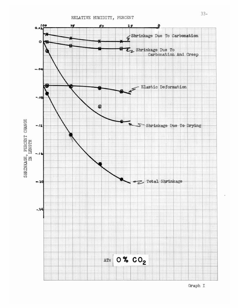
During C02-f'ree airdrying (85 days) -0.015 -0.067 -0.092 -0.117During subsequent CO2exposure (90 days) -.0.000 -0.004 -0.010 -0.010Sub-total -0.015 -0~071 -0.102 -0.127Due to Loading -0.062 -0.062 -0.066 -0.070TOTAL -0.077 -0.133 -0.168 -0.197
Weight Change, percent
During C02-f'reeair drying -1.35 -4.31 -5.84 -6.39During subsequentC02 exposure +0.35 +0.61 +0.67 +0.59TOTAL -1.00 -3.70 -5.17 -5.80
Length Change, percentCarbonation Shrinkage
(:percent) +0.011 +0.007 0.000 -0.002Creep Flow(percent) -0.011 -0.011 -0.010 -0.010
32.
33.RELATIVE HUMIDITY, PERCENT
100+.02.
o
~ b, , .-
~ TTT
.. _JI
~ :
-.041
12: ~+-::~--4-+ --H--+-- ----'- --r- - -
~ ~ • --,- -r-- - - ..... --r+--r-t --++++---4--t--t-+-;::::;:: --i- +'---: -+-4-+ -=++-- _ -H----'--
- - ---+- ..... ~ ~ ~ ++---------.-l-W--t-----+- I 1-, =-._ -~:_
-T-;--'-'- ~: ~ -t- - .:::;:t i~ -++ -+---t+--'-:::=;::::;::::: -----n---r-- --t-+--+- --4-.: ~n=+=+ H
+-~
-tt+=~:ttr -t 1:-+* i'x:: j: -8:+=+.- :;- H-~ z-:-Ii :~ r+-t+
--:R+
+-
::r:h
-.1a,+--t--t-
I
-+- H+++-H+++
--t-l +
+
0%... ~ .. ,_ 'u---"---
Graph I

TABLE II
.03% CO2
LENGTH AND WEIGHT CHANGE AT RELATIVE ffiJMIDITmS SHOv7NNominal Sample: 1 by 1 by 6ft: in.
97% H.R. 76% H.H. 52% R.H. 33% R.H.
Length Change, percent
During C02-free airdrying (85 days) -0.015 -0.067 -0.092 -0.117During subsequent CO2exposure (90 days) -0.012 -0.035 -0.044 -0.012Sub-total -0.027 -0.102 -0.136 -0.129Due to Load.ing -0.062 -0.062 -0.066 -0.070TOTAL -0.089 -0.164 -0.202 -0.199
Weight Change, percent
During CO2-freeair drying -1.35 -4.31 -5.84 -6.39During subsequentC02 exposure +0.68 +0.87 +1.09 +0.60TOTAL -0.67 -3.44 -4.75 -5.79
Length Change, percentCarbonation Shrinkage
(percent) 0.000 -0.024 -0.032 0.000Creep Flow(percent) -0.012 -0.011 -0.012 -0.012
34.

REIATIVE HUMIDITY, PERCENT 35.
100+.O'a.
If' o
t-++-
o -e~'o
t.!. "'t). it; on d' -=tG ~ee\fu
:
-.0
t-1-t-
-
- :::::=.~~
+-F- ~~~~;~:-~_~~ +-- :-: ~ ..w..
-+-h _.~ ~...,...~ _ -+-~ - f-'-L
I"""'" -rT~ - -'--l---; ..........- -- -rl-
.: - .-=~t:- ::-:-+ - ~:: --+-r-r- +.. - - - -~ ..... +-+- ------
+++---fJ.:-.~ +-t
~ -t:: ;J-::,~ :;.'!1ot-al =S. -~~.
I t_~+:.=:4'1: \.-r-t::++ ~ ~
-+~ ~
-.24:t W-.L..;
...l.f- -llJ'; >++.~
t-t+
=Ett ---.1- -
T :t~+t
!tit~
-, (G.
-.1'1.
Graph II

36.
TABIE III
50% CO2
IENGTH AND WEIGHT CHANGE AT RELATIVE HUMIDITmS SHOv1NNominal Sa.nr.p1e:1 by 1 by 6t:- in.
97% H.H. 76% R.H. 52% R.H. 33% R.H.
Length Change, percent
During C02-f'ree airdrying (85 days) -0.015 -0.067 -0.092 -0.117During subsequent CO2exposure (90 days) -0.034 -0.082 -0.103 -0.049Sub-total -0.049 -0.149 -0.195 -0.166Due to Loading -0.062 -0.062 -0.066 -0.070TOTAL -0.111 -0.211 -0.261 -0.236
Weight Change, percent
During C02-f'reeair drying -1.35 -4.31 -5.84 -6.39
During subsequentC02 exposure +0.87 +2.33 +3.29 +0.66TOTAL -0.48 -1.98 -2.55 -5.73
Length Change, percentCarbonation Shrinkage
(percent)Creep Flow(percent)
-0.024
-0.010 -0.008
-0.098
-0.005
-0.038
-0.011

RELA TIVE HUMIDI TY, PERCENT 37.
'00 T" ~O '1 0t.
I S . e e rl'O -c-'- - ...., L. -~n-'a0
-+=T--F, ,
I -4-++
~,:"1l
i 1 ~. "-g
4 t" :t'I .LL
-- ~I
..L +-L
~ i- T...--- i iR~I~TI -.. :-t -H
'i ~ I
t-~-T
01 + -r--, '
;R":-1-+ [t ---:--tt~s H
~~ , .~ r -~ -
I -hi+-r+
i ' , -+-++ ~:t - -r~'- ' ,
+-+++~-f--T""-+",-
+H-+ ..-- I ~
''a.+++-- ~'
n:, -H+ :::=.. .I- -J..+.
-++ -;-+++ I T I~., ' ' ......,. -;-- ~-'-i'- -
, ,
-++~f+i- +~++-++- 'E::..f# +-
-- --+-+--'--l-
-+ \1
: • - - +-t- ->---+ ~++.,--.+-- ._+
u. =- -. --=.:...r ~ :::G...= --t+~~- ~ --- 'X --~r+-t-t- ++ ---0- ..,..::t ::tEE -4++- ~ ~+ -+-~--H-h- T =-:.~: '-~''';''. - :..,C ~H-++"
--i-...:~~
-f-L+ -4+t rl--' -..- ; ~ -0-'-.
........f-T -'''to --+- ++- -+++- -t+++ --t-t-4 -----,..f~ 'T"'t-T+
+-+++- t-
SIE:t:.. ~ --+-- ~-f~-+=---+-~ .., ~
++H-~+ 't::t++ -++ '--+-- _ --':-:.1:'r+ --:...,...,. , -'-+
:--.::= +-+- +- -'-- +-4-..., _.~ r ......'- -M+-:- :t1ll -+-l-+ i+ W--. -+--- --+-+-
i:tti=f-++-h.- -l-~_
H--4t- ... • T' .•• -'- +-H- -++-,.. +~ ~~ . . . - ~ .• -.,.....,..-+---
!Elti-~:-:---..:. -.-++- ~ -+t
.It ~: ~ .. =+...,..,...,..... .t+~-+-
--
~- :..~,~~ i..-+++..LH+ ___H-~ ...... -+....0.-
, .~ ...,• _ ...... _T . -..... ........ --+-++ .....--I--t--'-+ --'-H
,~+~ --. :-:- ~~--
-'-++--+ ;.,+-'C't. ',:- .LU...2.4 ..
---,. +-:=t;= + +-- ~ " "Ii iit::!:I ~-'--iL-~ --'--
4- -'-~ -t+1 -to -"-:t -+-<_ -1--'-++ i+ ++++- ++-t-+-
+-+-+- M--"- ,-..-. ..:::r::t:: -.-M- ++--H--~+..... ~~~l ++>+ " ..
-rt+-tr +~:: -: ilff -
1 , , -.4.- . .., -1 '_-H-~~ ++-i=H# ~,..4 I
. -+-~"'1""""""'"-+-.~ -+- .. +;... :tttt -t+- 1:a +~rr
t+ ->- -+++~ ,-'=tP:t --.---1rl-+-
t
" l-
t++ +r ++-- f-t->--J..+.
- '._~ L'. 50 % CO2.t
-.
+.0
-.0
-.
~
~0
8 -.~::x::08
re~..t5~;2 -~~CJ)
Graph III

TABlE IV
100% CO2
IENGTH AND WEIGHT CHANGE AT RELATIVE HUMIDrrmS SHOVTNNominal Sample: 1 by 1 by 6l':- in.
97% R.H. 76% R.H. 52$ R.H. 33% R.H.
Length Change, percent
During C02-f'ree airdrying (85 days) -0.015 -0.067 -0.092 -0.117During subsequent CO2exposure (90 days) -0.029 -0.095 -0.ll6 -0.067Sub-total -0.044 -0.162 -0.208 -0.184'
Due to Loading -0.062 -0.062 -0.066 -0.070TOTAL -0.106 -0.224 -0.274 -0.254
'Height Change, percent
During C02":f'reeair drying -1.35 -4.31 -5.84 -6.39During subsequentC02 exposure +1.54 +3.20 +4.59 +1.19TarAL +0 .19 -1.11 -1.25 -5.20
Length Change, :percentCarbonation Shrinkage
(percent) -0.016 -0.085 -0.110 -0.055Creep Flow(percent) -0.013 -0.010 -0.006 -0.012
38.

REIATIVE HUMIDITY, PERCENT 39.
o
• I!'" & • o
. ,.l-+-
-r4 ::j::t!=- -+-t-'-
~ ee i~-r---
:iE~~----,....;...
+ ~~~ ;;-~t':
:~~-, ~---'~~T._--I::;... _ :--"-- i I
--: ..;..:..-:. -+--+-+- : -~
,- .~ -"---- -~. "
,-+ T'~' ~ ~ ~ +. -=- :++- -.--4-+- ~.--"-~ I- ~~ .. ~ -_. '- ~ -+-t-'-'-
- . ~ ~ +-l-4- ~ :. --:::=t --+t-t- ~-i-"- ----+--'--
~ '. -1.
t - I
, . i B +
tj
,ti+-+-+-t-'-
":
t.-+ ;1
I
-++- t-
:
~~.
-r-T +
I
~ ~r.;
~-L -- I :r
-l
=i-+- -r-
f-,
+t1- +1
~
Jt\~,'t'~
-.0 II \~\'++-~::'W-+
..~ +_\L
:1-. , ~.:t.'~
_.0 8
,- ~ --..+
fll_: 100 %C02r , r , 'rT~ .,-, ,n T"
Graph IV

TABLE V
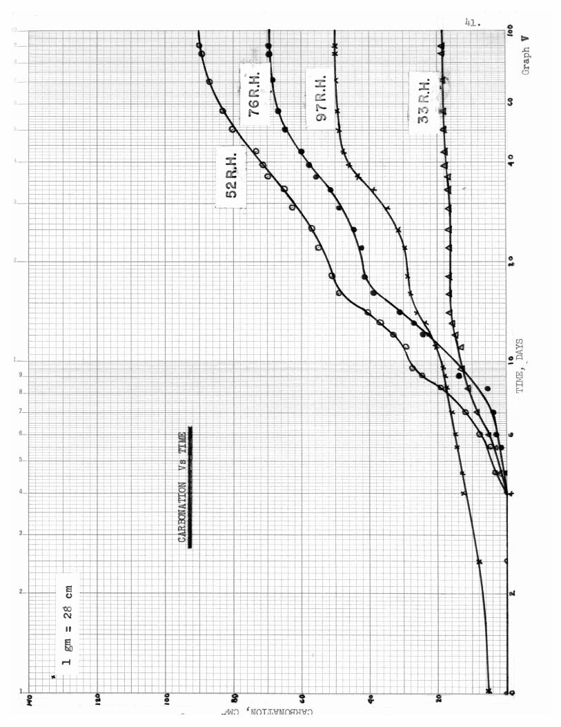
CARBONATION VS. TIME
Time Carbonation Carbonation Carbonation Carbonation(Days) at gy% R.H. at 76% R.H. at 5'C/a R.H. at 33% R.H.
0 0 0 0 0.4 1.0 0 0 0
1.4 5.7 0 0 02.5 8.1 0 0 04.0 12.6 .2 0 04.6 12.9 .2 3.5 2.55.5 14.5 1.9 4.5 4.06.0 14.9 2.8 8.0 5.57.0 16.2 4.0 12.0 8.58.3 17.5 5.8 19.1 11.69.0 18.0 14.0 24.5 12.89.5 18.2 19.5 27.5 13.2
11.0 20.5 20.9 29.3 13.612.0 22.4 24.0 33.1 14.713.0 23.9 27.2 37.0 16.014.0 26.2 31.0 40.1 16.516.0 23.1 39.0 49.1 16.518.0 29.0 41.0 51.0 16.522.0 29.5 42.4 55.0 16.625.0 31.6 44.5 57.0 16.929.0 35.1 49.0 62.5 16.933.0 38.4 51.8 65.0 17.636.0 43.4 55.9 69.9 17.639.0 46.2 57.9 71.4 18.043.0 47.5 60.1 73.4 18.050.0 49.2 65.1 80.0 18.357.0 49.7 67.1 83.1 18.371.0 50.0 68.5 86.9 18.385.0 50.1 69.4 89.2 18.390.0 50.1 69.6 90.8 18.3
40.
41.
o..II
I
Ii-+-
r-=+=l-:
--
1-_1-
_1- +-1 I
-+
.r
-I-t- +-
Frr--
I
-I--- -
-~-
-t--t _
-~- ••, Z~ .
JII..-f-- -- 0:--,-- (gc-t-== r--
.,-,
=+=-~ :::=f::I,c:-: 3c 3:-~.=l=-~3"
--
I
+- --I-
r+-'-f-II
-r-'
::=:j:::-~ ~_.::+= d-a:::--:-_L .-
--'-- --+--I I
I-,+f-r-~-r~E
9-+ -=J:::--ff-=: =f .;;L1Ji-
8 =i:---t -.t=i: -=FEi=E =F-;j:~-t--!
II I ; I
Ii
~ '-II~ e_-l.-+_, t)~ -t-+ . :==i=t=.: -cof--:B . -- - N- ~
I II-
I
f--..-l.. ..........
So-f----+---t-<
f--:+-' -f-- -
f--I- -J r-f -1--,-1--
.' I 1
I I I I1
=0~
- -j--
---- --L-..+-
't-'-+-f- ,-;-,-.
I
I
3 ---+ I
II

TABIE VI
RATES OF CARBONATION VS. TIHE
Time Rate at Rate at Rate at Rate at(Days) 97% R.R. 76% R.H. 52% R.H. 33% R.H.
0 0 0 0 01.5 3.7 0 0 04.0 2.0 0 0 05.5 1.2 4.2 .3 3.66.5 1.1 5.7 1.8 3.07.8 1.1 4.8 1.3 2.79.5 0.6 7.5 6.9 1.0
10.5 1.2 3.8 9.7 0.511.5 1.7 2.8 6.2 0.712.5 1.8 3.8 2.2 1.314.0 1.9 3.5 3.3 0.615.5 1.4 3.8 3.7 .217.0 0.8 2.8 4.0 022.0 0.1 0.8 1.0 '026.0 0.6 1.1 .3 .139.0 0.9 1.1 .9 .143.0 0.4 .8 .7 050.0 .3 .6 .6 057.0 .1 /' .6 0.0
71.0 0 0 .3 080.0 0 0 .2 090.0 0 0 .1 0
42.

- '-
10
9
8
7
6
5
-
t-+4 _++
I
-+-t
9
8
7
:= == = ~:--===>=
,-----
-+---- 1--
,, I
= tt= ~lI
, ',.

IV. DISCUSSION OF RESULTS
Photographic DataThe samples were broken and tested with phenolphtalein which
showed alkali reaction on part of the broken side of the specimen but
little or no reaction on the outside surface (which had been in contact
with the carbonic gas). Thus this test showed that the lime originally
present near the surface has suffered a chemical change. It is im-
portant to have in mind that the cement gel is ultimately affected by
the action of carbonic gas. Therefore the phenolphtalein test should
be considered only as a close approximation of '\-Thattruly is the depth
of carbonation.
Photographs I, II, III, and IV show the depth of carbonation
of the specimens tested. The carbonation increased toward the center
of the sample as the gas diffused inside the sample. Notice the depth
of carbonation for the samples maintained. at 52 percent relative
humidity is markedly increased in comparison with the corresponding
sample at the same carbonic gas concentration.
Figure 3 shows the qualitative depth of carbonation observed
in the tested samples.

III carbonated depth
t:I uncarbonated depth
97% 76% 52% 33%
0%.03%
50%
100%
FIGURE 3
Qualitative Depth. of Carbonation
Absorption Curves for 50% C02
The carbonic gas used during the carbonation period showed
that the optimum carbonation occurs at 52% relative humidity for the
50% CO2 content. The apparent explanation for such action is that the
sample in 52% relative humidity contained the optimum water for car-
bonation on its pores. Therefore the process started as soon as the
gas dissolved in the water. Probably the samples that ,{ere drier did
not contain sufficient water to start such action in a large scale
until some water was released by the initial reaction.
Carbonation will proceed until the gas cannot get in contact
with the :free lime on the saIl1J?leinterior., but only indirectly., by
propagation by the water produced by external carbonation. The samples
44.

at higher relative humidities contained large amounts of \-Taterin their
pores. This water prevented the occurrence of gaseous diffusion of
carbonic gas on the sample. Since some calcium ions are counter-
diffusing toward the surface it was expected. that some calcium car-
bonate was going to be precipitated. The calcitun carbonate will close
(clog) the pores preventing carbonation to reach any further stage.
It seems that under these environmental conditions the nature of this
clogging lies in the formation of caCo3.6H20 which is physically
bigger than ordinary caC03. The initial gas diffusion in the free
water on the surface accounts for the early increase in rate of
absorption of the wetter samples.
The Rate of Carbonation
The rate of carbonation of the samples (see Graph VI) shows
very interesting results. The absorption of CO2 by the sa.rnpleswas
observed to be a maximum during the early stages of the carbonation
period. The inference is that most of the carbonation action occurs
shortly after (during the first two weeks) the samples are in contact
with the atmosphere. The absorption slows down after the saturation
of the surface water with carbonic gas. Part of this gas combine s with
dissolved calcium hydroxide and precipitates calcium carbonate; the
rest diffuses inside the sample and continues the reaction until it is
used up.
45.
It is interesting to notice too) that the carbonation process
started 4 days later for the 76) 52) and 33 percent relative humidities

46.
samples. This was probably due to the absence of excess moisture or
large amounts of free water in the surface of these saw~les. The in-
creased amount of moisture will initially dissolve a larger anIDunt of
carbonic gas than would dissolve in samples with these deficiencies.
It is of interest that the ra~e of absorption of CO2 de-
creases (ultimately becomes zero) as a function of time. The apparent
explanation is that there is an absence of material susceptible to
the action of carbonation, and that the carbonation is dependent upon
the permeability of the carbonated depth.
Length and.Weight Change at Different Relative Humidities
The graph of relative humid.ity vs. shrinkage shovled that the
shrinkage due to water loss increased as the relative hunddity decreased.
The weight data showed. the same trend with respect to 1-;eightof the
sample, i.e., increased shrinkage decrease 1-leight.
The shrinkage due to carbonation was optimum in the vicinity
of the 50% relative humidity. From Graphs I, II, III, and rv the
general shape of the carbonation curve was established for different
carbonic gas concentrations.The creep flow of the samples was fairly constant at dif-
ferent relative humidities for low carbonic gas concentrations.
The creep flow seems to be reduced for samples subjected to
higher carbonic gas quantity at the optimum relative humidity (50%
R.H.). The author suspects that the Itsealing action" of the carbonated
crust has a bearing on such behavior. A more reasonable explanation

lies in the possibility that the carbonation shrinkage of the loaded
specimens was slightly lower due to partly closing of the pores under
load.
The elastic deformation upon loading increased for drier
sam;ples, i.e., the sanr.PlesvThich stabilized at lovrer relative humid.i':'
ties exhibited larger deformations. This may be explained by the
expected decrease in modulus of elasticity of drier sar.~les.
The total shrinlmge curves showed that the action of higher
concentrations of CO2 does not necessarily increase the magnitude of
the total shrinkage significantly.

v. RECO~~ENDATIONS
1. That more extensive analysis should be made of the mechanism of
carbonation on shrinkage and creep.
48.
2. Tests should include such variables as water cement ratio, specimen
size and carbonic gas concentration.
3. Tests should be run to determine the magnitude al1d rate of water
loss due to simultaneous drying and carbonation.
4. Cement type and methods of curing seem to influence receptiveness
and should be investigated ~ully.
5. The time of testing should be increased to maximize creep
deformation.
6. Tests should be made to determine the action of the rate of car-
bonation for subsequent industry application.
7. The rate of carbonation of samples maintained at 100% carbonic
gas concentration should be measured using a similar technique
to the one employed on the 50% carbonic gas concentration on this
report.
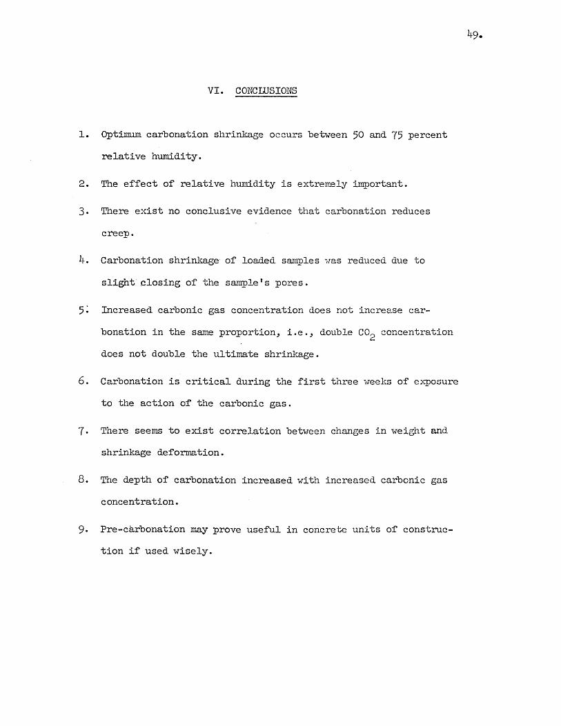
VI. CONCLUSIONS
1. Optimum carbonation shrinkage occurs between 50 and 75 percent
relative humidity.
2. The ef'f'ectof' relative humidity is extremely im:Portant.
3. There exist no conclusive evidence that carbonation reduces
creep.
4. Carbonation shrinkage- of' loaded samples i"as reduced due to
slight closing of' the sa~lefs pores.
5: Increased. carbonic gas concentration does not increase car-
bonation in the same proportion, i.e., double CO2 concentration
does not double the ultimate shriny~ge.
6. Carbonation is critical during the f'irst three weeks of' exposure
to the action of' the carbonic gas.
7 · There seems to exist correlation betvleen changes in weight and
shrinkage def'ormation.
8. The depth of' carbonation increased with increased carbonic gas
concentration.
9. Pre-carbonation may prove useful in concrete units of' construc-
tion if'used wisely.

APPENDICES
50.

APPENDIX A
Test ProcedureThe stages involved are casting, curing, stabilization,
loading and carbonating.
CastingThe samples (see Photograph 5) used in this experiment con-
sisted of litx I" x ~n long mortar prisms prepared in the molds
shown.
51.
Photograph 5
SPECIMEN AND MOLD

Plugs were inserted at the end of each sample as reference
points to measure shrinkage deformation. Further information with
respect to the use of this mold is provided in A.S.T.M. Standard
C157-54T.The mortar was prepared from a blend of four A.S.T.M. Type
I Portland cements, locally available (mON CLAD,DRAGON,ATLAS,and
HERCUIES). This blend was obtained by mixing equal weights of each
brand of cement and, mixing throughly with a mason1s trovTel. The sand
used was standard Ottawa sand, well graded.
A mixture of' 940 gm. of cement and 470 grn. of water was used,
giving a water-cement ratio of 0.50 by weight. The mixture was tested
for normal consistency according to CI09-58. If the mortar displayed
a lower consistency, it was disregarded and an increased amount of'
sand was used repeating the following process of mixing.
The water was placed in the bowl; approximately half of the
cement was added and mixed for 30 seconds. The remainder of the cement
was added and stirred for 30 seconds. At the end. of that time a paste
of uniform constitution was obtained. The sand was added to the cement
and mixed with irregular movements for two minutes. The normal con-
sistency test followed. Once the normal consistency had been reached
(100-110 percent inc.rease in lower diameter of test cone) the amount
of sand was recorded.
The final proportions of' the mortar were:
240 gm. of cement
470 ml. of water
2,350 gm. of sand
52.

53.
This can be expressed as I part water ~ 2 parts cement and 5 parts sand
by weight. The ratio of: cement to sand was 1/2.5 by weight.
The specific gravity of the mortar was measured in the labora-
tory and compared with that calculated from the individual specific
gravities of the mortar particles. The difference in the specific
gravities was found to be approximately 8%. This shows that the
mortar was fairly porous •.
The molds were f"illed and tampered by using a small wooden
rod until the cavity was completely filled with mortar. Trowelling
was necessary~ to assure a uniform surface of the sample~ on the top
part of" the mold. Sixty-four samples were needed for the test.
Curing
The molds containing the samples were placed in the moist
curing room which had a temperature of" 73°F and a 50 percent relative
humidity. They were covered with wet burlap. After 24 hours in the
molds the specimens were stripped-out and maintained in the same room,
and covered with wet burlap f"or 7 days.
At the end of the curing period the samples were measured
and weighed using the equipment shown in Photographs 6 and 7.
Stabilization
The sample stabilization with respect to weight and length
due to water loss was accomplished by using desiccator jars with
humidities controlled by saturated solutions of dissolved chemicals.
(Re:fer to Appendix B :for further information of these chemicals.)

-- Photograph6--
MEASURTIlG SAMPIE TIl THE UPRIGHT GAGE
, Photograph 7
WEIGHING OF SAMPLES
54.

The samples lose moisture until the interior humidity is
in equilibrium with the surrounding atmosphere.
The specimens were placed inside the desiccator jars as
shownin Photograph 8. Notice that between samples a small wooden
stick provides the necessary rollers to prevent any restraining o:f
the samples.
A suction pump 1vaS used to removethe air inside the jars
and replace it with air :free o:f CO2• The CO2was removed:fromthe
air by drawing it through a saturated solution o:f calcium hydroxide.
Under these conditions the samples were kept :for 85 days.
At the end o:f that time it was assumedthey were completely
stabilized with respect to weight and length.
Oncethis stage o:f the project was reached the samples were
weighed and measuredby the sameprocess used a:fter curing.
The :foregoing procedure assures that subsequent shrinkage
and creep will be isolated :frominitial water loss shrinkage.
Loading
Creep :flowas well as shrinkage was considered to be
important so hal:f the stabilized samples were subjected to 675 pounds
per square inch compressive stress. Companionspecimens loaded and
unloaded were exposed to 0, .03, 50, and 100 percent carbonic gas
concentration at :four different relative humidities: 33, 52, 76,
and CJ7.
55.

Photograph 8
STABILIZATION OF SAMPIES
56.
-Photograph 9
LOADED & UNLOADED
SPECIMENS m' JARS

57.
Photograph 10 shows the attachment used to measure the
loaded sample changes in length.
The specimens were loaded by means of the loading frame shown
in Photograph 11.
The hall inch deformation required on the spring, to develop
675 pounds, was measured by the Ames Dial Gage attached to the lower
plate next to the sample and the base of the moving part of the hy-
draulic jack. Photograph 12 shows the details of the operation. The
nuts of the frame bolts were tightened sufficiently to reduce the load
applied by the jack to zero.
Photograph 10
~URING SAMPIE ON LOADING FRAME

Photograph 11
HYDRAULIC COMPRESSION
MACHINE AND
LOADING FRAME
58.
- Photograph 12
MEASURmG SPRING
DEFORMATION

59.
The shrinkage due to loading was measuredby the gage shown
in Photograph 10.
Carbonation
After the loading phase the samples were subjected to car-
bonic gas concentrations of 0, .03, 50, and 100 percent with relative
humidities of 33, 52, 76 and 97 percent.
The relative humidities 'Within the jars were maintained by
chemical solutions. The carbonic gas concentrations were maintained
by different mechanismsas described below.
The zero percent carbonic gas concentration was obtained by
the samebubbling methodused to obtain CO2-free air during the
stabilization phase. The specimenswere sealed in the zero percent
CO2atmosphere until the end of the carbonation period. See ;Photo-
graph 13.
Normalcarbonic gas concentration was maintained by circulating
atmospheric air through the jars using a suction pumpworking inter-
mi ttently . See top part of Photograph 14.
A mixed atmosphere consisting of 50 percent carbonic gas
and 50 percent air 'Wasmaintained inside four 5 gallon jars. The
detailed procedure for maintaining this atmosphere is explained in
AppendixB. Photograph 15 shows someof those jars.
The 100 percent carbonic gas concentration was maintained
by the circulation of pure carbonic gas. The lower part of Photograph
14 shows the samples under such treatment.

Photograph 13CARBONATION WITH ZERO PERCENT C02
AT DIFFERENT RELATIVE RUMIDITJES
-PhotOgraph 14
CARBONATION WITH .03 AND 100 PERCENT C02
AT DIFFERENT RELATIVE HUMIDrrIES
60.

~
Photograph 15CARBONATION \oTITH 50 PERCENT C02
-----
Photograph 16M&ASURING RELATIVE HUMIDrry
61.

62.
AppendixB showsthe details of construction of' all the
f'oregoing equipment.
During the carbonation stage it was desirable to measure
the relative humidity of' the air inside the carbonation chamberas
a check. A lIDewPointerll humidity gage was used. This gage provided
a methodof measuring relative hvmidity without disturbing the atmos-
phere inside the jar. The principle of its performance consisted of
expanding adiabatically a sample of gas, at a def'inite pressure ratio,
until the dewpoint is attained. By meansof' tables provided by the
manufacturer and a psicrometric chart for different carbonic gas con-
centrations. The "DewPointer" was not used where the carbonic gas
concentration.:was other than as in normal air.
The carbonation period was assumedto last 90 days; at the
end of which the samples were removedfrom the jars. The loaded
samples were measuredon the frame and the unloaded samples by the
"Up-right" gage. The samples were unloaded using the compression
machine and weighed.
It was desirable to"investigate the depth of carbonation of
the samples. For this the samples were cut and drops of phenolphthalein
were applied to the newly exposed surface. Phenolphthalein in the
presence of an alkali turns a pink color. Whenthe surface is not
alkaline in nature the phenolphthalein turns transparent upon contact.
A more satisfactory and less fugitive indicator for this purpose was
Naphtol Green B, which does not color the carbonated surface, but,
instead, stains the inner portion green.

APPENDIX B
Desiccator and CommercialJars
A constant relative humidity in the atmosphere surrounding
the samples was desired. The various relative humidities required
were obtained by the use of' salt solutions reco~nded in the
AmericanSociety f'or Testing I~terials, Proceedings (1936). The
saturated solutions of' these chemicals in the presence of' excess
water in the atmosphere will dissolve someof' the crystals in the
bottom of' the container ~ until equilibrium is attained between the
liquid and the vapor above it. Subsequent decrease in relat.ive
humidity maycause the solution to give up moisture and precipitate
salt crystals.
The saturated solutions of' the f'ollowing salts provided
the desired relative humidities at 70oF.
Salt Relative Humidity (%)Potassium Sulf'ate (K2S04) 97
SodiumChloride (NaGl) 76
SodiumDicromate (Na2Cr207.2H2O) 52
MagnesiumChloride (MgCl2.6H20) 33
To maintain the conf'ined atmosphere, the smallest practical
conditioning chamber is the ordinary desiccator jar. Desiccator jars
are portable and have good ground covers which eliminate leaks and
consequent change in salt solutions. They can be placed in constant

temperature rooms or refrigerators. The actual humidity in the
desiccator jars was measured by calculating relative humidity :from
the sa~t solution used. The connnercial jars were sealed with para:f:fin
and the desiccator jars with stop-cock grease.
Loading Frame
The design o:f a mechanism that could maintain load on the
sample while in the jars was built as shown in Photograph 17.
Photograph 17LOADING FRAME AND SAMPlE
64.

This loading device is rugged, light, ef'f'icient and
economical. The load is transmitted to the sarn;pleby means of a
compression spring. Ball bearings are provided to apply the com-
pression load through the longitudinal axis of' the sample.
The whole mechanism is based on HookeI s Law. A known dis-
tortion will be applied to the spring without exceeding its elastic
limit. The spring chosen in the design had a low ttspring constant";
the reason for this is small contractions of the sam;ple will not
of'f'set the value of' the load exerted by more than I or 2 percent.
Small marks were f'iled on the edges of' the steel plates.
next to the sample to serve as ref'erence points from which to take
the measurements.
Hydraulic Compression Machine
This mechanism consists of' a rigid frame with a hydraulic
jack as the load applying unit. The machine was designed to provide
a def'inite def'lection on the frame spring and maintain it until the
nuts on the loading f'rame were tightened.
Figure 4 shows some details of' the compression machine and
loading frame.
Carbonic Gas Concentration Controls
Figures 5, 6, and 7 will show how the 0, .03 and 100 percent
carbonic gas concentrations were controlled.
To maintain an equal amount of' air and carbonic gas, two
jars (with the samples inside) were f'illed with the two gases. One

*jar contained CO2and the other atmospheric air. The gases were
mixedby recirculating the contents in a closed circuit by meansof
a hand pump.
~fuenthe samples start using carbonic gas the concentration
of it is going to change the original content of 50 :percent CO2to
a low'er value. Therefore it is required to replace the amountused.
Referring to Figure 8, if a vacuum.is created at the jar intake (A)
the one wayvalve aclaims someof the carbonic gas stored to replace
that absorbed by the samples. The pressure drops in the CO2reservoir
causing sone water in the second reservoir to flow through the siphon.
The water level in the CO2reservoir increases. Both levels were
maintained at equal heights by adding water at point (B) that was
opened to the atmosphere. This vlill maintain a constant pressure of'
one atmosphere in the specimens jar. CO2can be added to the reser-
voir by attaching a clamp to point (n) and supplying the gas through
(C). So~ water will be removedthrough (B) to account for the
increase in volumeof' gas in the system. The amountand rate of
use of CO2can be measuredby this apparatus.
*The .03 :percent of CO2percent in normal air is neglectable forall practical purposes.
66.


BIBLIOGRAPHY
1. Portland Cement Association, "Concrete Information ST-21.1I
2. Bresler, B., "1-That'He Don't KnowAbout Concrete,1f VlesternArchitect &Engineer, December 1960.
3. Powers, T. C. and Brownyard, Proceedings American ConcreteInstitute (1947).
4. Powers, T. C., "The Physical structure and EngineeringProperties of Concrete. It
5. Davis, R. E.; Davis, H. E. and Hamilton, "Plastic FlovTof'Concrete Under Sustained Stress," Proceedings A.S.T.r.l.,V. 34, Part II (1934).
6. Ostlund; L., ttStability of Concrete Structures Submitted toLong Time Loads,1I Nordisk Betong (1957).
7. Vlasha, G. Vl., "Plastic F10vT of Thin Reinforced Slabs,"Proceedings A.C.I., Vol. 19, November 1947.
8. Lea, F. M. and Lee, C. R., Symposium on "Shrinkage andCracking of Cementive lIlaterial, n Society of Chemical Industries.
9. Portland Cement Association, "Volume Changes of' ,Concrete. It
10. Troxell and Davis, Concrete, McGraw-Hill Book Co., Inc., 1956.
11. American Society of' Testing Materials, "Significance of Testand Properties of Concrete and Concrete Aggregates. tt
12. Toennies, H. T., "Artificial Carbonation of Concrete MasonryUnit, It A.C.1. Journal, February 1960.
13. Voss, H. C., tlExterior Masonry Construction, n National LimeAssociation Bulletin 324 (1956).
14. Bessey, G. E., tlEffects of Carbon Dioxide on Cement and LimeNortars," Journal Society of Chemical Industries, Vol. 52,1933.
15. Shiedeler, Joseph J., "Investigation of the l>'loisture-VolumeStability of Concrete Nasonry Units," Bulletin D3, PortlandCement Association, Chicago, Illinois, ~mrch 1955.
72.

16. Verbeck, G. J., ttCarbonation of Hydrated Portland Cement, ft
Bulletin 87, Portland Cement Association, Chicago, Illinois,February 1958.
17. Leber, I. and Blakey, F. A., ttSomeEffects of Carbon Dioxideon Mortars and Concrete,1t A.C.I. Journal, Vol. 28 NO.3,September 1956 (Proceedings V. 58), pp. 295-308.
18. Brady, F. L., Itrvlod,ification of Physical Properties of CementProduced by Carbonation, It Cement and Cement Manufacture,v. 4, 1931.
19. Lea, I. and Desch, The Chemistry of Cement and Concrete, (1956).20. Nansfield, G. A., "A Problem in Thermodynamics, I! Rock-Products,
Vol. 51, 1948.21. Meyers, S. L., "Effects of Carbon Dioxide on Hydrated Portland
Cement and Concrete. It
22. Kauer, J. A. and Freeman, R. L., "Effect of Carbon Dioxideon Fresh Concrete, tt Proceedings A.C.I., Vol. 52, p. 447, (1955).
23. Heber, J. and, Mathei, R., ItFind Carbon Dioxide Under Pressurean Efficient Curing Agent for Cast Stone, It Concrete, July 1941,pp. 31-39.
24. Powers, T. C. and Brovmyard, T. L., "Studies of the PhysicalProperties of Hardened Portland Cement Paste," Bulletin 22,Portland Cement Association, Chicago, March 1948.
25. American Society of Testing ~~terials Standards - 1958, Vol. 4.
73.