the effect of the placement of viscous fluid linear …
TRANSCRIPT

2nd
Turkish Conference on Earthquake Engineering and Seismology – TDMSK -2013
September 25-27, 2013, Antakya, Hatay/Turkey
1
THE EFFECT OF THE PLACEMENT OF VISCOUS FLUID LINEAR
DEVICE IN THE DYNAMIC RESPONSE OF STRUCTURE
L. Djellouli1 and A. Ounis
1
1
Civil Eng. and Hydraulics Department, University of Biskra, Algeria
Email: [email protected]
ABSTRACT:
For a seismic increased protection, new technologies have been developed among which are " the passive energy
dissipation devices." The absorption of most of the seismic energy input in the primary structure of buildings and
reducing as much as possible damage to structural elements is the main objective of these devices. In this work,
a modeling of viscous fluid linear device is performed as passive energy dissipation system to control the
dynamic response of structures due to a seismic motion. A comparative study with a traditional structure is
conducted to analyze the influence of this type of damping on the dynamic behavior of the structure. The effect
of the placement of these devices in the dynamic response of structure is also studied.
KEYWORDS: Seismic engineering, energy dissipation, viscous fluid damper, seismic response.
1. INTRODUCTION
Because of the seismic vulnerability of our country, the development of innovative technological concepts for
increased protection of structures and people is a challenge for researchers engineering vis-à-vis the adverse
effects generated during seismic movements.
Structural engineers cannot be unconscious of the damages caused by earthquakes on human and materials plans
that have plagued our country, which explains the need to consider the challenge of integrating new technologies
such as seismic protection systems.
The traditional approach in seismic design is based on the combination of the resistance with the ductility to
mitigate the seismic loading. To do this, the engineer is based on the ductility provided by the materials in order
to avoid disasters and ensure the stability of the structure to severe earthquakes. Structural damage is often
caused by plastic deformation suffered by the structure due to the high level of energy generated during a
seismic movement. For seismic protection, new technologies have been developed among which are the "energy
dissipation devices passive
The main objective of the incorporation of the "energy dissipation devices'’ is to absorb of a significant part of
the seismic energy and reducing as much as possible, the damage in the structural elements. Among the devices
of passive energy dissipation, we find the viscous fluid dissipator. These devices are used successfully in new
buildings as well as rehabilitation of existing structures. As an example of use of these devices, which proves to
be an effective method of seismic protection, we can cite the San Francisco Civic Center (United States), the
Raikai Hospital (Japan) and the Mayor tower (Mexico).
The objective of this study is the modeling of an energy dissipation device linear viscous fluid type such as
seismic protection system to control the dynamic response of structures in seismic movements.

2nd
Turkish Conference on Earthquake Engineering and Seismology – TDMSK -2013
September 25-27, 2013, Antakya, Hatay/Turkey
2
2. DESCRIPTION OF THE STRUCTURE
The structure used in our study is a building of reinforced concrete of 20 levels with rectangular form (Figure.1a
and Figure.1b) in plan 16x20m² including three spans in the longitudinal direction and four in the transverse
direction (Figure.1b).The main beams are of section 50x30 cm2 and the secondary section beams are 40x30
cm2, the sections columns are presented in Table 1, and the height of each stage is 3 m with thickness of the
slap is 16cm (that not lose its shape in their plan) in order to satisfy the assumption of rigid diaphragm. It is
assumed that the inherent damping ratio of the structure is 5%.
Table 1. The sections columns
levels 1-5 6-10 11-15 16-20
Section of
column(cm2)
70х60 60х50 50х40 40х30
3. MODELING OF FLUID VISCOUS DAMPER (VFD)
For the analysis of structures with added dampers different mathematical modeling techniques have been
developed. Different models of increasing complexity are examined by Reinhorn and al. (1995) for viscous
dampers. Symans and Constantinou (1993) showed that the Maxwell model is sufficient to capture the frequency
dependence of the viscous damper (Fig.2a). And they also showed that, below a frequency of about 4 Hz, the
model can be further simplified in a purely viscous damper model.
It is indicated in that the 274-FEMA damping force of viscous damper is proportional to the velocity with a
constant exponent lying between 0.5 and 2. In the preliminary stages of analysis and design, exponent velocity 1
is recommended for more simplicity. In this study, based on these references, the behavior of fluid viscous
dampers is modeled by a linear damper (Fig.2.b), and modeling of ETABS 9.7 is made by the data block NLlink
property.
Figure 1. (b) 3D view of the structure
without viscous fluid damper
Figure 1. (a) Plan view of the structure

2nd
Turkish Conference on Earthquake Engineering and Seismology – TDMSK -2013
September 25-27, 2013, Antakya, Hatay/Turkey
3
4. LOCATION OF FLUID VISCOUS DAMPERS
The structures will be analyzed and studied with and without energy dissipators viscous fluid. These dampers
will be placed in the diagonal bracing structures. Each floor contains two dissipators in the X direction and two
dissipators in the Y direction. Fig. 3 shows a plan view of the location of structures with dampers and Figures 4
shows the elevation view of the structure. The additional damping is ξ= 15% and ξ= 20%, while the critical
damping of the structure is 5%, the effective damping ratios of the structure will be ξeff =20% and ξeff= 25%.
Figure 4. Elevation view of the structure a) portico axis 1, b) portico axis 5
c) portico file A and d) portico file D
Figure 2. (b) Structure with diagonal viscous fluid damper
C
Figure 2. (a) Maxwell model
C K
Figure 3. Plan view of the structure with
the location of dissipators

2nd
Turkish Conference on Earthquake Engineering and Seismology – TDMSK -2013
September 25-27, 2013, Antakya, Hatay/Turkey
4
5. SEISMIC EXCITATIONS
The structures were studied under the influence of the components 140 ° and 230 ° of El Centro earthquake
(Imperial Valley) (1979) recorded by Array # 6 station with maximum acceleration, PGA = 0.376g and PGA=
0.436 g respectively. These two components are applied in the X direction and Y direction respectively (Figures
5 and 6). And the components 0 ° and 90 ° of the Loma Prieta earthquake (1989) recorded by Hollister station
with maximum acceleration PGA= 0.369g and PGA = 0.178g respectively, these two components are applied in
the X direction and Y direction respectively (Figures 7 and 8).
6. COMPARISONS OF THE RESULTS
6.1. Comparison “Structure with and without Viscous Fluid Damper”
The dynamic analysis carried out for the two structures (with and without VFD) enabled us to compare the
results of displacements in the levels, and the base shears force in the two directions. These results are
represented as follows:
Figure 5. Time history of Array # 6 of the
seismic El Centro in X direction
Figure 6. Time history of Array # 6 of the
seismic El Centro in Y direction
Figure 7. Time history of Hollister of the
seismic Loma Prieta in X direction
Figure 8. Time history of Hollister of the
seismic Loma Prieta in Y direction

2nd
Turkish Conference on Earthquake Engineering and Seismology – TDMSK -2013
September 25-27, 2013, Antakya, Hatay/Turkey
5
6.1.1. Displacements
According to the figures (9, 10, 11, 12) that illustrate the displacement in the levels of the structure with and
without viscous fluid damper for different effective damping ratios (ξeff= 5%, ξef= 20% and ξef= 25%). we notice
a decrease in displacement of the structure with additional damping compared to without dampers in all seismic
excitations except the component loma-prieta in the X direction.
Figure 9. Comparison of displacements Under
the El Centro earthquake in X direction
Figure 10. Comparison of displacements Under
the El Centro earthquake in Y direction
(à base fixe et à base LRB) dans le sens YY
(à base fixe et à base LRB) dans le sens XX
Figure 12. Comparison of displacements Under
the Loma-Prieta earthquake in Y direction
(à base fixe et à base LRB) dans le sens YY
(à base fixe et à base LRB) dans le sens XX
Figure 11. Comparison of displacements Under
the Loma-Prieta earthquake in X direction

2nd
Turkish Conference on Earthquake Engineering and Seismology – TDMSK -2013
September 25-27, 2013, Antakya, Hatay/Turkey
6
6.1.2. Base Shear Forces
According to the figures 13, that illustrate the base shear forces of the structure with and without viscous fluid
damper for different effective damping ratios (ξeff= 5%, ξef= 20% and ξef= 25%). we notice a decrease in base
shear forces of the structure with additional damping compared to without dampers in all seismic excitations
excepted the component loma-prieta in the Y direction for ξeff = 20%, Were the base shear forces is augmented.
Figure 13. Comparison of base shear forces
Observation
We conclude that it is not only increasing the percentage damping ratios of the dissipator, it ensures good
displacement and stability of the structure. To achieve acceptable results, we changed the distribution of fluid
viscous dampers in the structure and examined several structures with different locations of damper. In this
paper we present the location that given best results (Fig.14).
a) b) c)
Fig. 14: Elevation view of the structure with VFD a) 3D, b) portico axis 1 and 5, c) portico file A and D

2nd
Turkish Conference on Earthquake Engineering and Seismology – TDMSK -2013
September 25-27, 2013, Antakya, Hatay/Turkey
7
6.1.3. Displacements
After the analysis of the new structure we obtained curves shown in Figures (15, 16, 17 and 18) reflecting the
displacements of each level.
Figure 15. Comparison of displacements
Under the El Centro earthquake in X direction
Figure 16. Comparison of displacements Under
the El Centro earthquake in Y direction
(à base fixe et à base LRB) dans le sens YY
(à base fixe et à base LRB) dans le sens XX
Figure 17. Comparison of displacements Under
the Loma-Prieta earthquake in X direction Figure 18. Comparison of displacements under
the Loma-Prieta earthquake in Y direction
(à base fixe et à base LRB) dans le sens YY
(à base fixe et à base LRB) dans le sens XX

2nd
Turkish Conference on Earthquake Engineering and Seismology – TDMSK -2013
September 25-27, 2013, Antakya, Hatay/Turkey
8
These figures clearly show that the incorporation of viscous dampers in the structure of this new distribution
reduces displacement in all levels under all seismic excitations.
6.1.4. Base Shear Forces
Figure 19. Comparison of base shear forces
6.2. Comparison ''Structure with the First Emplacement / Structure with the Second Emplacement''
The dynamic analysis carried out for the two structures (the first emplacement and the second emplacement)
enabled us to compare the results of displacements and the base shears force in the two directions X and Y as
follows.
6.2.1. Comparison of Displacements
.
Figure 20. Comparison of displacements Under
the El Centro earthquake in X direction
Figure 21. Comparison of displacements Under
the El Centro earthquake in Y direction
(à base fixe et à base LRB) dans le sens YY
(à base fixe et à base LRB) dans le sens XX

2nd
Turkish Conference on Earthquake Engineering and Seismology – TDMSK -2013
September 25-27, 2013, Antakya, Hatay/Turkey
9
According to the results of comparison, the Figures 20, 21, 22 and 23 shows that the structure with the second
emplacement gives a significant reduction in displacement in the levels compared to the structure with the first
emplacement of viscous fluid damper.
6.2.2. Comparison of Base Shear Forces
The comparison of the base shear forces for the two structures (first and second emplacement of viscous fluid
damper) in two directions X and Y is represented on the Figure 24. This result shows that the second location
reduces the base shear best then the first location.
Figure 24. Comparison of the base shear forces for the two
structures
Figure 22. Comparison of displacements
Under the Loma-Prieta earthquake in X
direction
Figure 23. Comparison of displacements Under
the Loma-Prieta earthquake in Y direction
(à base fixe et à base LRB) dans le sens YY
(à base fixe et à base LRB) dans le sens XX

2nd
Turkish Conference on Earthquake Engineering and Seismology – TDMSK -2013
September 25-27, 2013, Antakya, Hatay/Turkey
10
The emplacement of the dissipators in the structure plays a very important role in the response of the structure.
We note For this structure in the first proposal that the percentage reduction of the base shear force under the
El-Centro-X component for ξeff = 20% is 22.06% while in the second proposition is 31.74%.
6.3. Hysteretic Behavior
A hysteretic behavior of the damper is described by a hysteresis loop (closed curve), which shows the force-
displacement relationship, the surface or the area of the loop is the energy absorbed by the viscous fluid damper.
To illustrate this dissipation, we have plotted the hysteresis loops of the viscous fluid damper on the 10th and 20
th
level of the structure under seismic excitations in both the X direction and for the effective damping ratio ξeff =
20% and ξeff = 25%.
Figure 25. Hysteresis loops of the 10th level under the El Centro earthquake following
X-axis, for a) eff =20% and b) eff =25%.
Figure 26. Hysteresis loops of the 10th level under the Loma-Prieta earthquake following
the X axis for a) eff =20% and b) eff =25%.
2nd
Turkish Conference on Earthquake Engineering and Seismology – TDMSK -2013
September 25-27, 2013, Antakya, Hatay/Turkey
11
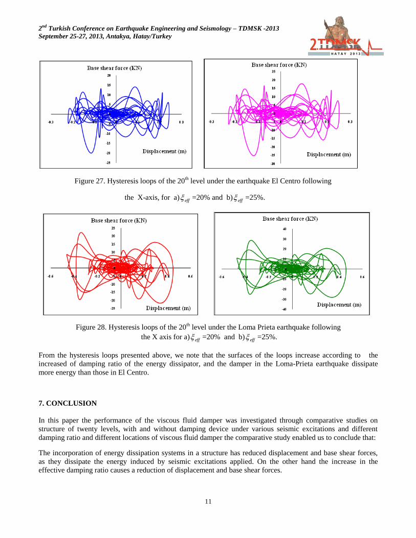
Figure 27. Hysteresis loops of the 20th level under the earthquake El Centro following
the X-axis, for a) eff =20% and b) eff =25%.
Figure 28. Hysteresis loops of the 20th level under the Loma Prieta earthquake following
the X axis for a) eff =20% and b) eff =25%.
From the hysteresis loops presented above, we note that the surfaces of the loops increase according to the
increased of damping ratio of the energy dissipator, and the damper in the Loma-Prieta earthquake dissipate
more energy than those in El Centro.
7. CONCLUSION
In this paper the performance of the viscous fluid damper was investigated through comparative studies on
structure of twenty levels, with and without damping device under various seismic excitations and different
damping ratio and different locations of viscous fluid damper the comparative study enabled us to conclude that:
The incorporation of energy dissipation systems in a structure has reduced displacement and base shear forces,
as they dissipate the energy induced by seismic excitations applied. On the other hand the increase in the
effective damping ratio causes a reduction of displacement and base shear forces.

2nd
Turkish Conference on Earthquake Engineering and Seismology – TDMSK -2013
September 25-27, 2013, Antakya, Hatay/Turkey
12
Surfaces that represent the hysteresis energy absorbed by the energy absorber increases viscous fluid loops in
accordance with the increase in the additional damping ratio for all seismic excitations applied. As well as
energy dissipators dissipate more energy at a medium or high long-term excitation (as part of Loma Prieta along
the X-axis) and at medium or high excitement of short duration (component of El Centro along the X axis).
The location of the dissipators in the structure plays a very important role in the response of the structure. We
remarks with the structure of twenty levels in the first proposal that the reduction percentage of the displacement
under the El Centro-X component for ξeff = 20% is 43,44% while in the second proposal is 54,23%. And in the
base shear force under the El Centro-X component for
ξeff = 20% is 22.06% while in the second proposal
is 31.74%.
REFERENCES
FEMA 274, (1997), “Guidelines for the Seismic Rehabilitation of Building”, chapter 9, Seismic Isolation and
Energy Dissipation, NEHRP.
T.T.Soong and M.C.C costantinou (1994). “Passive and active structural vibration control in civil engineering”.
State university of New York at buffalo.
Kelly T., (2001), “In Structure Camping and Energy Dissipation”, Holmes Coulting Group Ltd
M.C.C costantinou and M.D.Symans “Experimental study of seismic response of buildings with supplemental
fluid dampers”. The structural design of tall building, vol.2, 93-132 (1993)
T.T.Soong and B.F. Spencer Jr. “Supplemental energy dissipation: state of the-art and state-of the practice”.
(2002) Elsevier Science Ltd. Engineering Structures 24 (2002) 243–259
Semih S. Tezcan , Ozan Uluca, “Reduction of earthquake response of plane frame buildings by viscoelastic
dampers”. 2003 Elsevier Ltd. Engineering Structures 25 (2003) 1755–1761.
Ali Sehat Tabatabaei, (2006), “Energy dissipation systems for seismic resistance” copyright, 2003-2006 Iran
Civil Center.
George Vezeanu and Andrei Pricopie, “Design considerations for buildings with non linear viscous dampers”
CSI, ETABS (Extended Three Dimensional Analysis of Building Systems) Nonlinear Version 9.7
(2003).Integrated software for structural analysis and design. Computers and structures, Inc, Berkeley,
California, USA.