the effects of cfrp orientation on the strengthening of
TRANSCRIPT

THE STRUCTURAL DESIGN OF TALL AND SPECIAL BUILDINGSStruct. Design Tall Spec. Build. (2016)Published online in Wiley Online Library (wileyonlinelibrary.com/journal/tal). DOI: 10.1002/tal.1282
The effects of CFRP orientation on the strengthening of reinforcedconcrete structures
Mehdi M. Lima1, Jeung-Hwan Doh1*, Muhammad N. S. Hadi2 and Dane Miller1
1School of Engineering, Griffith University, Gold Coast, QLD, Australia2School of Civil, Mining and Environmental Engineering, University of Wollongong, Wollongong, NSW, Australia
SUMMARY
In recent years, the strengthening and retrofitting of structural members using externally bonded carbon fibrereinforced polymer (CFRP) materials has gained a great deal of attention. This has eventuated from the su-perior properties of composite materials, including high elastic modulus, higher strengths and lighterweights. This paper presents a finite element analysis that has been validated against laboratory tests oftwo reinforced concrete (RC) beams, two columns, two slabs and six walls. The main focus is on the ulti-mate failure load of these members as they have different CFRP orientations to the loading direction. Theanalysis result shows a sound agreement with the experimental data regarding the ultimate failure load ofRC samples, except for the RC wall. In fact, the RC wall, while under eccentric axial load, confirmed thatthe CFRP orientation was parallel to the loading direction, and it proved to be an insignificant contributionin the ultimate failure load of the samples. This finding demonstrates that more experiments should beconsidered when investigating the influence of CFRP on the ultimate strength of strengthened RC walls.Copyright © 2016 John Wiley & Sons, Ltd.
Received 21 September 2015; Revised 17 January 2016; Accepted 16 February 2016
KEY WORDS: concrete structures; confined concrete; carbon fibre reinforced polymer; reinforced concrete wall;strengthening; concrete damage plasticity
1. INTRODUCTION
A large number of concrete structures need to be strengthened due to the deterioration of structures thatis largely influenced by environmental effects, poor initial construction or a lack of required mainte-nance. Based on the load-carrying capacity of structures and demand, a vast array of strengtheningmethods may be utilized. While the traditional method of the strengthening/retrofitting of concrete struc-tures is commonly used steel plates and jackets, there are some disadvantages, including an increase inthe self-weight of structures, and that it is labour-intensive and susceptible to fatigue and corrosion. Dueto the rapid advancement in construction material, technology has led to the inspiring achievement ofbeing able to secure safer, more economical and functional buildings (Bakis et al., 2002). Of the inno-vative materials, fibre reinforced polymer (FRP) appears to be a superb solution for the retrofitting andstrengthening of reinforced concrete (RC) structures because of its unique properties, including highstrength-to-weight ratio, high fatigue endurance, environmental degradation and corrosion resistance(Hollaway and Head, 2001; Teng et al., 2002; Tumialan et al., 2002; Teng et al., 2003; Zhang, HsuC-T, and Moren, 2004; Zhang and Hsu, 2005; Zhao and Zhang, 2007). In contrast to the traditionalmethod of retrofitting structures, the handling and transportation of FRP is much more user-friendly.It is also durable and very flexible when applying it to the various shapes of structural members. Further,it is easy to install, with a negligible increase in structural size and weight (Alsayed, Al-Salloum, andAlmusallam, 2000; Clarke, 2003; Obaidat, Heyden, and Dahlblom, 2010; Meneghetti et al., 2014).
*Correspondence to: Jeung-Hwan Doh, School of Engineering, Griffith University, Gold Coast, QLD 4222, Australia.E-mail: [email protected]
Copyright © 2016 John Wiley & Sons, Ltd.

M. M. LIMA ET AL.
The application of FRP is dependent upon the type of structural member plus its behaviour. It can beused to enhance the load (axial, flexural or shear) capacities, ductility, rigidity, the remaining fatiguelife and the durability against harsh environments. An extensive experimental research has alreadybeen conducted on FRP application on the strengthening of concrete structures (Spadea, Bencardino,and Swamy, 1998; Pantelides et al., 1999; Neale, 2000; Rahimi and Hutchinson, 2001; Nanni, 2003;Thanoon et al., 2005; Kim et al., 2012; Napoli et al., 2013) and also national codes of standardsdevoted separate chapter for the FRP applications (JSCE, 2000; FIB14, 2001; ISIS, 2001; ACI 440,2002; TR 55, 2012).However, the effectiveness of confinement between FRP and concrete is reportedly much reduced
by applying load at eccentricity, particularly lateral FRP confined structural elements such ascolumns and walls. In addition, to the best of author’s knowledge, there has not been finite elementmethod (FEM) investigation on the behaviour of RC walls under eccentric axial loads. Therefore,this paper focuses on a comparative study of using finite element analysis. The experimental andanalytical work of beams, columns, slabs and walls has contributed to a greater understanding ofthe behaviour of FRP confinement with various concrete elements that have been utilized in thisstudy.This paper initially presents a brief overview of an experimental programme undertaken by previous
researchers on strengthened RC beams, columns, slabs and walls. The load capacity of the typical testresults is then compared with predicted results from the ABAQUS package. A nonlinear geometry andmaterial properties were employed to analyse the behaviour of RC elements.
2. APPLICATION OF CFRP IN CONCRETE ELEMENTS
Many researchers have investigated the flexural and shear behaviour of strengthened/retrofitted RCbeams, with some review papers also being published (Bakis et al., 2002; Smith and Teng, 2002;Pendhari, Kant, and Desai, 2008; Chin, Shafiq, and Nuruddin, 2014). Usually, the FRPsheet/laminate is used in the tension side of the beam and perpendicular to cracks; the strength andstiffness increases significantly as compared with situations where fibres are placed oblique to thecracks (Norris, Saadatmanesh, and Ehsani, 1997; Grace et al., 1999; Hong et al., 2010; Altin et al.,2011; Rahai and Saberi, 2011; Kim, Kim, and Kim, 2015; Lu et al., 2015; Tanarslan, Kumanlioglu,and Sakar, 2015; zgür Yurdakul and Avşar, 2015). The effect of FRP on the ultimate capacity ofRC beams has been reported in several research outcomes. Some of these results, including strength-ening scheme and the enhancement of the ultimate strength, are presented in Table. 1.The FRP confinement has been used for the strengthening of both normal and high-strength concrete
columns. To investigate the behaviour of FRP-confined concrete columns, experimental tests and the-oretical methods have been applied (Barghi, Azadbakht, and Hadad, 2012). The effect of FRP in theultimate capacity of RC columns is reported in the previous studies. Some of these results, includingstrengthening scheme, load type and enhancement of the ultimate strength, are presented in Table. 2.The effect of FRP in the ultimate capacity of RC slabs has been investigated. Some of these results,including strengthening scheme and enhancement of the ultimate strength, are presented in Table. 3.Based on these results, the CFRP significantly enhanced the ultimate strength of slab by up to 184%in some cases.Wall panels often experience eccentric loads due to a range of loading conditions including corbel
element applied to the wall, imperfections in construction, an uneven loading condition on top of thewall or due to temporary loading during operation and/or maintenance. Many researchers have inves-tigated the behaviour of RC walls with various material properties, geometry and boundary conditions(Saheb and Desayi, 1989, 1990; Doh and Fragomeni, 2005; Doh and Fragomeni, 2006; Fragomeni,Doh, and Lee, 2012). However, little research has been carried out on the CFRP strengthening methodon the RC wall under eccentric axial loads. Mohammed, Ean and Malek (2013) conducted experimentson 16 one-way RC walls with two different CFRP layouts on the wall surface. Authors observed thatthe CFRP applications on RC walls could increase the ultimate strength of the wall from 10% up to80%, depending on the opening size and CFRP arrangement.
Copyright © 2016 John Wiley & Sons, Ltd. Struct. Design Tall Spec. Build. 2016;DOI: 10.1002/tal

Table
1.Som
eprevious
research
studieson
theapplicationof
CFRPin
beam
s.
Author
Num
bers
andsize
ofelem
ent
[#no.clearspan
×b×D
(mm)]
Loadtype/spacing
betweentwo
pointsloading
(mm)
Average
concrete
strength
(MPa)
Strengthening
scheme
Maxim
umload
increm
ental
(upto
%)
TSB
UW
CW
CS
A90
AN90
Grace
etal.(1999)
#6.2
743×152×292
SP
48√
√73
KhalifaandNanni
(2000)
#5.2
340×(T-beam)×
(150
×405
web)×
(380
×100flange)
TP/200
35√
√√
√148
Alm
usallam
andAl-Salloum
(2001)
#2.2
050×150×200
TP/200
38√
√√
190
KhalifaandNanni
(2002)
#8.4
576×15
0×305
TP/310
23√
√√
√√
120
Alagusundaram
oorthy,Harik
and
Choo(2003)
#12.
4576
×230×342
TP/916
31√
√50
Zhang
etal.(200
4)#12.
762×101×203
SP&
TP/254
42√
√√
√√
√122
Zhang
andHsu
(2005)
#11.
1675
×152×229
SP&
TP/304
45√
√√
80Cao
etal.(2005)
#18.
1700
×150×223
TP/400,6
0026
√√
√80
Hosny
etal.(2006)
#1.3
000×(T-beam)×
4570
×(160
×300w
eb)×
(460
×60
flange)
Cyclic
TP/750
25√
√√
17
Kotynia
etal.(2008)
#10.
4200
×150×300
TP/1400
36√
√√
√68
JumaatandAlam
(2008)
#1.2
000×125×250
TP/700
30√
√√
54Ibrahim
andMahmood(2009)
#1.2
440×150×250#2.
1830
×230×380
SP&
TP/1700
30√
√√
√80
Siddiqui(2010)
#6.2
000×200×300
TP/500
35√
√√
√√
37Ceroni(2010)
#18.
2000
×100×180
TP/240,4
4034
√√
√√
√√
72Obaidat
etal.(201
0)#4.1
560×
150×300
TP/520
29√
√√
√33
Sen
andJagannatha
Reddy
(2013)
#2.1
300×14
0×200
TP/433
22√
√√
√√
√125
El-Saikaly
andChaallal(2015)
#6.4
164×(T-beam)
(152
×406web)×
(508
×102flange)
TL/2056
35√
√122
SP,singlepointloading
atcentre;T
P,twopointsloading;
TSB,twosidesbonding;
UW,U
-wrap;
CW,com
pletewrap;
C,contin
uous;S
,strip;A90,angleto
longitu
dinalaxis=90;
AN90,angle
tolongitu
dinalaxis≠90.
THE EFFECTS OF CFRP ORIENTATION ON RC STRUCTURES
Copyright © 2016 John Wiley & Sons, Ltd. Struct. Design Tall Spec. Build. 2016;DOI: 10.1002/tal

Table
2.Som
eprevious
research
studieson
theapplicationof
CFRPin
columns.
Author
Num
bers
andsize
ofcolumn
[#no.columnheight×b×D
(mm)or
R(radius)
(mm)]
Loadtype/lo
adeccentricity
(mm)
Average
concrete
strength
(MPa)
Strengthening
scheme
Maxim
umload
increm
ental
(upto
%)
FW
PW
HW
VS
ParvinandWang(2001)
#6.3
05×108×108
CO
&EC/7.6,1
5.2
21√
100
LiandHadi(200
3)#3.1
400×R75
&hunchedR117.5
EC/42.5
100
√√
7Matthys,T
outanjiandTaerw
e(2006)
#6.2
000×R200
CO
36√
√√
70Hadi(2006)
#6.1
400×R75
&hunchedR117.5
EC/42.5
32√
23Hadi(2006)
#3.9
25×R102.5
CO
&EC/25,
5057.3
√-
Hadi(2007)
#4.9
05×R102.6
EC/50
66√
√124
Maaddaw
y(2009)
#8.1
200×125×125&
hunched(250
×250)
EC/37.5,
54,7
1,107.5
29√
√37
Sadeghian,Rahai
andEhsani(2010)
#5.2
700×200×300&
hunched(200
×600)
EC/200,3
0040
√√
√130
Bisby
andRanger(2010)
#12.
304×R76
CO
&EC/5,1
0,20,3
0,40
33√
76Toutanjiet
al.(2010)
#2.2
000×355×355#1.
2000
×500×250
CO
37√
12
Abdelrahm
anandEl-Hacha
(2012)
#4.1
200×R150
CO
40√
38HadiandWidiarsa(2012)
#12.
800×200×200
CO
&EC/25,
5080
√√
18WuandJiang(2013)
#24.
300×R75
CO
&EC/10,
20,3
0,40,5
026.6
√300
Gajdosova
andBilcik
(2013)
#2.4
100×15
0×200
EC/40
32√
2Songet
al.(2013)
#4.1
500×250×250&
hunched(40,
50,5
00×250)
CO
&EC/20,
60,1
00,1
5030
√30
Pham,D
oanandHadi(2013)
#9.8
00×15
0×150
CO
&EC/25,
5073
√286
CO,concentric;
EC,eccentric;FW,fullwrap;
PW,p
artialwrap;
HW,h
elical
wrap;
VS,v
ertical.
M. M. LIMA ET AL.
Copyright © 2016 John Wiley & Sons, Ltd. Struct. Design Tall Spec. Build. 2016;DOI: 10.1002/tal

Table
3.Som
eprevious
research
studieson
theapplicationof
CFRPin
slabs.
Author
Num
bers
andsize
ofslab
[#no.clearspan
×b×D
(mm)]
Loadtype/lo
adspacing(m
m)
Concrete
strength
(MPa)
Strengthening
scheme
Maxim
umload
increm
ental(upto
%)
SA90
AN90
Lim
am,F
oret
andEhrlacher
(2003)
#1.2
600×2600
×100
SP
30√
√√
150
Mosallam
andMosalam
(2003)
#4.2
640×2640
×76
UP
33√
√√
184
Tan
andZhao(2004)
#6.2
300×2400
×150
TL/1100
39√
√√
81Enochsson
etal.(2007)
#6.2
600×2600
×100
UP
57√
√√
125
ElMaaddaw
yandSoudki(2008)
#1.1
500×500×100
TL/500
28√
√√
38Smith
andKim
(2009)
#2.3
200×2500
×160#1.
3200
×80
0×160
TL/1800
45√
√62
Elgabbaset
al.(2010)
#2.3
200×1200
×120
TL/984
32√
√70
Seliem
etal.(2011)
#2.3
353×NM
×115
TL/1524
18√
√√
30Anil,KayaandArslan(2013)
#6.2
800×1000
×150
TL/1000
20√
√√
60
SP,single
pointloadingat
centre;UP,uniform
pressure;TL,twolin
esloading;
S,strip;
A90,angleto
longitu
dinalaxis=90;AN90,angleto
longitu
dinalaxis≠90;NM,not
mentio
ned.
THE EFFECTS OF CFRP ORIENTATION ON RC STRUCTURES
Copyright © 2016 John Wiley & Sons, Ltd. Struct. Design Tall Spec. Build. 2016;DOI: 10.1002/tal

M. M. LIMA ET AL.
The CFRP sheet orientation in a strengthened beam, column and slab is perpendicular to the loadingdirection (Figures 1 and 2(a)). In these situations, fibres in CFRP will contribute to the carrying of theload by stretching through its principal direction. Therefore, the usage of CFRP in these elements en-hances the ultimate strength of the member. It should be noted that, in the RC wall panels, the loadingdirection and CFRP’s fibre orientation are parallel. As RC walls experience a shortening in the fibre’sdirection, a lower contribution of CFRP in ultimate failure load is expected (Figure 2(b)). As little re-search has been conducted on strengthening of RC walls, it is necessary to evaluate the behaviour ofthe wall through the numerical FEM as it is a cost-effective and time-effective method.Using the current experimental test samples (Smith and Kim, 2009; Siddiqui, 2010; Hadi and
Widiarsa, 2012; Mohammed et al., 2013), comparison tests were carried out for the performance ofthe FEM. This validation study is utilized to model the behaviour of beam, column, slab and RC wallsstrengthened by CFRP.
Figure 1. Loading direction and CFRP orientation.
Figure 2. Loading direction and CFRP orientation.
Copyright © 2016 John Wiley & Sons, Ltd. Struct. Design Tall Spec. Build. 2016;DOI: 10.1002/tal

THE EFFECTS OF CFRP ORIENTATION ON RC STRUCTURES
3. EXPERIMENTAL WORK
Experimental data were obtained from previous experiments on strengthened beams (Siddiqui, 2010),columns (Hadi and Widiarsa, 2012), slabs (Smith and Kim, 2009) and RC walls (Mohammed et al.,2013). The detailed information of these experiments and results can be found in the original papers.The following section is a brief description of each experiment, as well as the material properties andthe enhancement of ultimate strength. The FRP material properties are presented in Section 4.5. In thisstudy, all experiments have been designated with N and S at the beginning for non-strengthened andstrengthened specimens, respectively. Therefore, the nomenclature of beams, NB and SB, are referringto the non-strengthened and strengthened beams. The same procedure is used for slabs (NS and SS),columns (NC and SC), walls (NW and SW) for non-strengthened and strengthened samples. Also,in RC walls, two different CFRP layouts are considered as SW-A and SW-D for alongside and diag-onal applications, respectively. The wall number is also shown with a number.
3.1. Beam
Six RC beams with two different reinforcement arrangements and three FRP patterns were loaded witha four-point bending configuration with a clear span (distance between supports) of 2000mm, with adistance between loads of 500mm. From these experiments, two beams (with and without CFRP) werechosen for numerical simulation. The beams were 300mm high, 200mm wide and 2000mm long. Thelongitudinal steel reinforcement consisted of three φ14 for tension and one φ6 for compression. Shearreinforcement was sufficiently provided with φ10 at 100mm rebars (as seen in Figure 3). The controlbeams were loaded up to failure, and in the other case, the CFRP was applied as the flexural strength-ening scheme, as well as two u-shaped anchors at the end of the beam near the restraint. The concretecompressive strength was 35MPa for both cases, and yield stress of reinforcement was 420MPa.Application of CFRP increased the ultimate failure load from 197.2 kN to 255.2 kN for NB and SB
samples, respectively. This is about 29.5% gain in the ultimate strength of the beam (Siddiqui, 2010).
3.2. Column
Sixteen identical RC columns were tested, with 12 of them under compression loading and four underflexural loading. Three different FRP confinements were investigated. From these experiments, twocolumns (with and without CFRP) under eccentric compression loading (eccentricity = 25mm) werechosen for numerical simulation. The columns had a square cross-section with a side dimension of200mm and a height of 800mm. The concrete cover was 20mm on each side of the specimen, as wellas on the top and bottom. All corners of the square cross-section were rounded (radius of 34mm) inorder to prevent the premature failure and to provide sufficient effect of confinement of the columns.The longitudinal reinforcement consisted of four φ12, and the transverse reinforcement was φ8 spacedat 100mm, while the distance was 50mm at both ends as seen in Figure 4(a). The control column wasloaded up to failure, and in the strengthened case, the CFRP was applied as one layer of CFRP withhorizontal orientation (Figure 4(b)). A special loading plate and mechanism were designed and usedin this study (Figure 4(c)). The concrete compressive strength was 79.5MPa for both cases, and yieldstress of longitudinal reinforcement and stirrups were 564MPa and 516MPa, respectively.
Figure 3. Beam specimen strengthened by CFRP and cross-section of beam (all dimensions are\ inmm) (Siddiqui, 2010).
Copyright © 2016 John Wiley & Sons, Ltd. Struct. Design Tall Spec. Build. 2016;DOI: 10.1002/tal

Figure 4. Column specimen strengthened by CFRP (all dimensions are in mm) (Hadi and Widiarsa,2012).
M. M. LIMA ET AL.
Application of CFRP increased the ultimate failure load from 1950kN to 2076 kN for NC and SCsamples, respectively. This is about 6% enhancement in the ultimate strength of the column (Hadiand Widiarsa, 2012).
3.3. Slab
Six simply supported one-way spanning RC slabs were tested, four of which had an opening at the cen-tre. All slabs were prismatic and rectangular in the cross-section and nominally 3400mm long and of160mm depth, with a clear span of 3200mm. From this experiment, two slabs (with and withoutCFRP) were chosen. The width of the slab was 800mm, and the concrete cover was 20mm on eachside of the specimen. The 12-mm-diameter steel bars were used as longitudinal and transverse rein-forcement, while the distance between bars was 200mm and 400mm in each direction, respectively,as seen in Figure 5. The control slab was loaded up to failure, and in the strengthened case, the CFRPwas applied as the flexural strengthening scheme with two layers of CFRP (Figure 6). The concretecompressive strength was 47MPa and 49MPa for control and strengthened slab, respectively. Theyield stress of reinforcement was 564MPa.The application of CFRP increased the ultimate failure load from 49.3 kN to 80.8 kN for NS and SS
samples, respectively. This is about 64% enhancement in the ultimate strength of the slab (Smith andKim, 2009).
3.4. RC wall
Eight one-way RC walls were tested with two different patterns. They had various opening sizes (5,10, 20 and 30 percentage) and were located at the centre. For all the wall series, aspect ratios (H/L),slenderness ratios (H/tw) and thinness ratios (L/tw) were 2, 20 and 10, respectively. From these exper-iments, two RC walls (with and without CFRP) were chosen. The height, width and thickness of thewall were 800mm, 400mm, 40mm, correspondingly. The concrete cover was 20mm on each sideof the specimen. The 5-mm-diameter steel bars were used as longitudinal and transverse reinforce-ment, and the reinforcement ratio of 0.004 and 0.007 in vertical and horizontal, respectively, as seenin Figures 7(a) and 8(a). The control wall was loaded up to failure in the strengthened cases; the CFRPwas applied at the tension face as one layer of CFRP all around the corner and 45° to the corner(Figures 7(b,c) and 8(b,c)). The concrete compressive strength was 15.57MPa, 18.24MPa and
Copyright © 2016 John Wiley & Sons, Ltd. Struct. Design Tall Spec. Build. 2016;DOI: 10.1002/tal

Figure 5. Slab specimen (all dimensions are in mm) (Smith and Kim, 2009).
Figure 6. FRP application (all dimensions are in mm) (Smith and Kim, 2009).
THE EFFECTS OF CFRP ORIENTATION ON RC STRUCTURES
16.36MPa for NW1, SW1-A and SW1-D, respectively. This value for NW2, SW2-A and SW2-D was15.79MPa, 15.06MPa and 17.04MPa, correspondingly. The yield stress of reinforcement was 478MPa.The application of CFRP around the corner of the openings increased the ultimate failure load from
85kN to 108 kN for NW1 and SW1-A specimens, respectively. This is about a 27% enhancement inthe ultimate strength of RC wall. For SW1-D, the failure load was recorded as 138.5 kN, which isabout a 62% gain in the strength of the RC wall (Mohammed et al., 2013).The application of CFRP around the corner of the openings increased the ultimate failure load from
73.7 kN to 82 kN for NW2 and SW2-A specimens, respectively. This is about an 11.2% enhancementin the ultimate strength of RC wall. For SW2-D, the failure load was recorded as 84.8 kN, which isabout a 15% gain in the strength of the RC wall (Mohammed et al., 2013).
4. NUMERICAL SIMULATION (MATERIAL PROPERTIES AND CONSTITUTIVE MODELS)
The materials used in the FEM analysis included steel reinforcing bars, concrete and FRP. In the fol-lowing section, the input material properties and associated constitutive models are discussed.
4.1. Modelling of steel reinforcing bars
The stress–strain curve of the reinforcement bar is assumed to be elastic perfect plastic material andidentical in compression and tension, as shown in Figure 9. In ABAQUS, the steel reinforcement is sim-ulated as truss elements embedded in a concrete region in which the concrete and the reinforcement
Copyright © 2016 John Wiley & Sons, Ltd. Struct. Design Tall Spec. Build. 2016;DOI: 10.1002/tal

Figure 7. Details of specimen reinforcement and CFRP layout (all dimensions are in mm) (Mohammedet al., 2013).
Figure 8. Details of specimen reinforcement and CFRP layout (all dimensions are in mm) (Mohammedet al., 2013).
M. M. LIMA ET AL.
share the same node and perfect bond is assumed. The elastic modulus, Es, and yield stress, fy, for allexperiments are presented in the previous section, and these values were used in the FEM model. Forthose experiments where elastic modulus was not reported, a value of 210GPa was considered in FEMsimulation. A Poission’s ratio of υs=0.3 was used for reinforcement rebars in all models.
Copyright © 2016 John Wiley & Sons, Ltd. Struct. Design Tall Spec. Build. 2016;DOI: 10.1002/tal

Figure 9. Schematic stress–strain behaviour of steel.
THE EFFECTS OF CFRP ORIENTATION ON RC STRUCTURES
4.2. Concrete
The uniaxial compressive strength f ′c for all samples is presented in the previous section. The concretestrain ε0, corresponding to the peak stress f ′c, is usually around the range of 0.002–0.003. A represen-tative value (ε0 = 0.003) suggested by ACI318-14 (2014) is used in the analysis. The Poission’s ratio υcof concrete under uniaxial compressive strength ranges from 0.15 to 0.22, and in this study, thePoission’s ratio of concrete is assumed to be υc=0.2 for all concrete instances. The initial modulusof elasticity of concrete Ec is highly correlated to its compressive strength and can be calculated withreasonable accuracy from the empirical equation AS3600 (2009):
Ec ¼ ρ1:5ffiffiffiffif ′c
qMPa where f ′c ≤ 40 MPa (1-1)
Ec ¼ ρ1:5 0:024ffiffiffiffif ′c
qþ 0:12
� �MPa where f ′c > 40 MPa; (1-2)
where ρ is the concrete density. The stress–strain relationship proposed by (Saenz, 1964) was used toconstruct the uniaxial compressive stress–strain curve for normal strength concrete (for beam, slab).
σc ¼ Ecεc
1þ Rþ RE � 2ð Þ εcεo
� �� 2R� 1ð Þ εc
εo
� �2þ R εc
εo
� �3;
(2)
where
R ¼ RE Rσ�1ð ÞRε�1ð Þ2 � 1
Rε, RE ¼ Ec
Eo, Eo ¼ f ′c
εoand Rσ =4 and Rε=4 were used (Hu and Schnobrich, 1989).
For high-strength concrete, the stress–strain relationship proposed by (Hsu and Hsu, 1994) wereused for 0 ≤ ε ≤ εo, n=1; for εo ≤ ε ≤ εd, n=1 if 0 < f ′c < 62 MPa; n=2 if 62 ≤ f ′c < 76 MPa,n=3 if 76 ≤ f ′c < 90 MPa; and n=5 if f ′c ≥ 90 MPa
0 ≤ ε ≤ εd; σc ¼ nf ′c β ε=εoð Þnβ � 1þ ε=εoð Þnβ ; β ¼ f ′c
65:23
� �3
þ 2:59: (3)
4.3. Concrete in tension
The tensile property of the reinforced concrete is modelled using a simple tension stiffening model. Alinear softening model (Figure 10) is used to represent the post failure behaviour in tension where thearea below the curve is the fracture energy Gf. In order to define the tension stiffening response, thestress–fracture energy approach is used with the fracture energy. For concrete under uniaxial tension,ft and Gf may be estimated from the following equations (CEB-FIP, 1990):
Copyright © 2016 John Wiley & Sons, Ltd. Struct. Design Tall Spec. Build. 2016;DOI: 10.1002/tal

Figure 10. Schematic stress–strain behaviour of concrete in tension.
M. M. LIMA ET AL.
f t ¼ 1:4f ′c � 810
� �23
(4)
Gf ¼ 0:0469da2 � 0:5da þ 26
f ′c10
� �0:7
; (5)
where ft the concrete tensile strength under is uniaxial tension, Gf is the fracture energy required to cre-ate a stress-free crack over a unit area and da is the maximum aggregate size. In the present study, if notest data are provided, it was assumed that da=20mm. Note that in Equation (5), f ′c and da are in MPaand mm, respectively, and Gf has a unit of N/mm (Bažant and Becq-Giraudon, 2002).
4.4. Concrete damage plasticity model
The concept of either damage or plasticity, or both, can be applied to model the nonlinearity behaviourof concrete under compression (Maekawa, Okamura, and Pimanmas, 2003). Damage and plasticity areusually defined by the reduction of elastic constants and permanent deformation, respectively. In liter-ature, both reduction in stiffness and unrecoverable deformation have been reported in concrete com-pression tests, indicating that the combination of the damage concept and plasticity is required torepresent the nonlinear behaviour of concrete (Maekawa et al., 2003). In this study, the simulationof RC beams, columns, slabs and walls has been carried out using the concrete damage plasticitymodel. In order to represent the inelastic behaviour of concrete, the concrete damage plasticity inABAQUS uses concepts of isotropic damage in combination with isotropic tensile and compressive plas-ticity (Hibbitt, Karlsson, and Sorensen, 2011). This method is briefly presented in this section. It as-sumes that the main two failure mechanisms are tensile cracking and compressive crushing of theconcrete material. The key aspects of this model for concrete in compression are damage variable,yield criterion, the flow rule and viscous parameter. A summary of these factors are presented asfollows.
4.4.1. DamageIt was assumed that the damage up to the concrete compressive strength (σu) was zero, and after thatpoint, the concrete compression damage increased monolithically in the softening branch (Jankowiakand Lodygowski, 2005). The compression damage was calculated according to Equation. (6):
dt ¼ 1� σσu
; (6)
where σ is the axial stress of concrete on the descending branch and σu is the stress of concrete at thepeak point.The concrete behaviour in tension was linear elastic until cracking was initiated. ABAQUS software
has three options to simulate the behaviour of concrete in tension including: stress–strain, stress–
Copyright © 2016 John Wiley & Sons, Ltd. Struct. Design Tall Spec. Build. 2016;DOI: 10.1002/tal

THE EFFECTS OF CFRP ORIENTATION ON RC STRUCTURES
displacement and fracture energy. To overcome unreasonable mesh sensitivity issues, the fracture en-ergy approach was used instead of the tensile strain. This was calculated as a ratio of the total externalenergy supply (Gf) per unit area required to initiate cracking in the concrete. This approach was sug-gested in a previous study (Sümer and Aktaş, 2014).In order to minimize mesh sensitivity in the slab, the post-failure behaviour of concrete was speci-
fied in terms of the stress–displacement response (Enochsson et al., 2007). These damage parameterswere similar to that of previous research carried out by Enochsson et al. (2007), where the fracture en-ergy (Gf) of the area under the stress–displacement curve was estimated to be 100N/m.It was assumed that the damage up to the concrete tensile strength (f ′t) was zero, and after that point,
concrete tensile damage increased monolithically in the softening branch and was calculated based onthe following formula:
dt ¼ 1� f i′
f ′t; (7)
where f ’ i is the axial stress of concrete on the descending branch and f ′t is the stress of concrete at thepeak point.
4.4.2. Yield criterionThe concrete damage plasticity model makes use of the yield function of Lubliner et al. (1989), withthe modifications proposed by Lee and Fenves (1998) to account for the different evolution of strengthunder tension and compression, as shown in Equation (8). The evolution of the yield surface is con-trolled by the hardening variables, eεtpl and eεcpl:
F σ;eε pl ¼ 1
1� αq� 3αpþ β eεpl bσmax
� �� γ �bσmax� � � σc eεcpl
≤ 0; (8)
where
α ¼ σbo=σcoð Þ � 12 σbo=σcoð Þ � 1
; 0:08 ≤ α ≤ 0:12 (9)
β ¼ σc eεcpl σt eεtpl 1� αð Þ � 1þ αð Þ (10)
γ ¼ 3 1� Kcð Þ2Kc � 1
; (11)
where bσmax is the maximum principal effective stress and σbo/σco is the ratio of initial equibiaxial com-pressive yield stress to initial uniaxial compressive yield stress. The most reliable in this regard are theexperimental results reported by Kupfer, Hilsdorf and Rusch (1969). After their approximation withthe elliptic equation, uniform biaxial compression strength σbo is equal to 1.16248 σco. The ABAQUS
user’s manual specifies default σbo/σco=1.16, which was used in all simulation. Kc is the strength ratioof concrete under equal biaxial compression to triaxial compression. Typical yield surfaces in thedeviatoric plane are shown in Figure 11 for different values of K. It must satisfy the condition0.5 ≤ Kc ≤ 1.0. The default value (2/3) was used in all FEM simulation; σc eεcpl
is the effective com-
pressive cohesion stress and σt eεtpl is the effective tensile cohesion stress.
The concrete damaged plasticity model assumes non-associated potential plastic flow. The flow po-tential G used for this model is the Drucker–Prager hyperbolic function:
G ¼ffiffiffiffiffiffiffiffiffiffiffiffiffiffiffiffiffiffiffiffiffiffiffiffiffiffiffiffiffiffiffiffiffiffiffiffiξσto tan ψð Þ2 þ q2
q� p tan ψ ; (12)
where σto is the uniaxial tensile stress at failure, ψ is the dilation angle measured in the p–q plane at
Copyright © 2016 John Wiley & Sons, Ltd. Struct. Design Tall Spec. Build. 2016;DOI: 10.1002/tal

Figure 11. Yield surfaces of the concrete damaged plasticity model in ABAQUS (Hibbitt et al., 2011).
M. M. LIMA ET AL.
high confining pressure and ξ is a parameter, referred to as the eccentricity, that defines the rate atwhich the function approaches the asymptote (the flow potential tends to a straight line as the eccen-tricity tends to zero). The default flow potential eccentricity is ξ =0.1, which implies that the materialhas almost the same dilation angle over a wide range of confining pressure stress values. In all FEManalysis, ξ =0.1 was used. The dilation angle for concrete slab, beam, RC wall and column were12°, 37°, 20° and 8°, respectively. Similar dilation angles for each case study were used in previousFEM investigation (Enochsson et al., 2007; Majewski, Bobinski, and Tejchman, 2008; Obaidatet al., 2010).
4.4.4. Viscous parameterThe viscoplastic regularization can be applied using the concrete damage plasticity for the generalizingof the Devaut–Lions approach. A viscous parameter μ upgrades the plastic strain tensor, and the dam-age parameter is derived using additional relaxation time. The viscosity parameter was set to 0 as rec-ommended by ABAQUS documentation; however, in specimens with a convergence problem, a smallviscosity parameter (μ=10�5) is considered after many sensitivity analyses were performed. Thisvalue is defined to improve the convergence rate in the concrete softening and stiffness degradationregimes. Similar approaches have been used in previous research studies where it is reported that ifthe viscosity parameter is 0, the solution becomes plastic and divergence is obtained directly aftercracking (Genikomsou and Polak, 2014).
4.5. FRP properties
The FRP material was considered as a linear elastic orthotropic material. Since the composite is unidi-rectional, it is obvious that the behaviour is essentially orthotropic. FRP primarily stressed in the fibredirection; therefore, the modulus in the fibre direction is the more important parameter. The elasticmodulus in the fibre direction of the unidirectional FRP material used in the FEM was provided inthe experiments. The FRP material properties are presented in Table. 4. A perfect bond was consideredbetween FRP and concrete in all samples as the simulation of debonding is out of scope of thisresearch.The CFRP was simulated as an orthotropic material that exhibits a different modulus of elasticity in
three main directions. This was achieved by using the ‘Engineering Constant’ option of the materialdefinition section in ABAQUS software.The modulus of elasticity in the main direction was considered as the value given in the experi-
ments. The modulus of resin was designated as the modulus of elasticity in the other two directions
Copyright © 2016 John Wiley & Sons, Ltd. Struct. Design Tall Spec. Build. 2016;DOI: 10.1002/tal

Table 4. Fibre reinforced polymer material properties for all specimens.
Specimen CFRP
Nominalthickness (mm)
Modulus ofelasticity (MPa)
Elongation atrapture (mm/mm)
Tensile strength(MPa)
Strengthened beam 1.000 77 280 0.0110 846Strengthened column 0.450 75 400 0.01860 1399Strengthened slab 0.117 259 000 0.0099 2559Strengthened wall 0.167 230 000 0.0210 4800
THE EFFECTS OF CFRP ORIENTATION ON RC STRUCTURES
(E22 and E33). In cases where the information of resin was not given in the experiments, 1–2% of E11
was assumed for E22 and E33 (Mosallam and Mosalam, 2003). Since the CFRP were subjected to uni-axial tension in the fibre direction only, these assumed parameters would not affect the uniaxial tensilebehaviour of the CFRP.The Poisson ratio was designated as 0.3, 0.3 and 0.45 forυ12, υ13 and υ23, respectively. The shear
moduli (G12, G13 and G23) were calculated based on the following formula:
Gxy ¼ ExEy
Ex þ Ey þ 2υxyEx: (13)
5. FEM ANALYSIS
In all numerical models, a full scale of the element was analysed. In the FEM, eight-node brick ele-ments (C3D8R) were used to model the concrete in beams, columns, slabs and RC walls. As theFRP are relatively thin in comparison with the concrete section, they were modelled by the four-nodeshell element. The FRP shell elements were attached to the concrete surface directly, and the interfacebetween concrete and FRP was assumed to be fully bonded. Mesh convergence sensitivity has beencarried out for all specimens in order to have a little difference in the element behaviour and failureload. An attempt was carried out to have a square element for all specimens. An appropriate contactwas also considered between loading plate and concrete element.
5.1. Mesh sensitivity
Mesh convergence sensitivity was performed for all specimens in order to achieve little difference inthe element behaviour and failure load. An attempt was carried out to have a square element for allspecimens. Herein, the mesh sensitivity study for RC slab was presented. Three mesh configurationswere used (Figure 12) including coarse, medium and fine mesh. In order to investigate the mesh sen-sitivity in the RC slab, the sizes of mesh for other parts, such as reinforcement bars, were maintained.Using a coarse mesh resulted in lower peak loads compared with the experimental outcomes. The de-flection response was much lower than that of the medium and fine mesh. The peak loads predicted forthe varied mesh densities were provided in Table. 5. The difference between the ultimate failure loadsby using fine and medium mesh was approximately identical, while the time cost for the fine mesh wasmuch higher. Therefore, the medium size mesh was adopted.
5.2. Riks method
In this study, the Riks method has been used for analysis of all numerical models. The Riks method isusually used to predict the unstable, geometrically nonlinear collapse of a structure and can include thenonlinear materials. Additionally, the Riks method often follows an eigenvalue buckling analysis toprovide complete information about a structure’s collapse. As finding the failure load of the struc-ture was the main purpose of this study and in order to have a consistent analysis method in all RCelements, the Riks method was preferred. Automatic stability was also used to avoid a divergence so-lution. For considering the geometric nonlinearity, Nlgeom setting was also activated.
Copyright © 2016 John Wiley & Sons, Ltd. Struct. Design Tall Spec. Build. 2016;DOI: 10.1002/tal
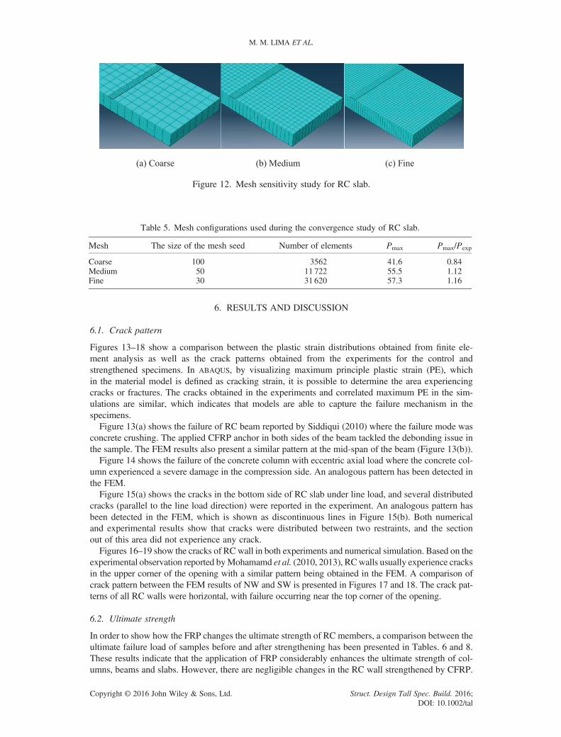
Figure 12. Mesh sensitivity study for RC slab.
Table 5. Mesh configurations used during the convergence study of RC slab.
Mesh The size of the mesh seed Number of elements Pmax Pmax/Pexp
Coarse 100 3562 41.6 0.84Medium 50 11 722 55.5 1.12Fine 30 31 620 57.3 1.16
M. M. LIMA ET AL.
Copyright © 2016 John Wiley & Sons, Ltd. Struct. Design Tall Spec. Build. 2016DOI: 10.1002/ta
6. RESULTS AND DISCUSSION
6.1. Crack pattern
Figures 13–18 show a comparison between the plastic strain distributions obtained from finite ele-ment analysis as well as the crack patterns obtained from the experiments for the control andstrengthened specimens. In ABAQUS, by visualizing maximum principle plastic strain (PE), whichin the material model is defined as cracking strain, it is possible to determine the area experiencingcracks or fractures. The cracks obtained in the experiments and correlated maximum PE in the sim-ulations are similar, which indicates that models are able to capture the failure mechanism in thespecimens.Figure 13(a) shows the failure of RC beam reported by Siddiqui (2010) where the failure mode was
concrete crushing. The applied CFRP anchor in both sides of the beam tackled the debonding issue inthe sample. The FEM results also present a similar pattern at the mid-span of the beam (Figure 13(b)).Figure 14 shows the failure of the concrete column with eccentric axial load where the concrete col-
umn experienced a severe damage in the compression side. An analogous pattern has been detected inthe FEM.Figure 15(a) shows the cracks in the bottom side of RC slab under line load, and several distributed
cracks (parallel to the line load direction) were reported in the experiment. An analogous pattern hasbeen detected in the FEM, which is shown as discontinuous lines in Figure 15(b). Both numericaland experimental results show that cracks were distributed between two restraints, and the sectionout of this area did not experience any crack.Figures 16–19 show the cracks of RCwall in both experiments and numerical simulation. Based on the
experimental observation reported byMohamamd et al. (2010, 2013), RCwalls usually experience cracksin the upper corner of the opening with a similar pattern being obtained in the FEM. A comparison ofcrack pattern between the FEM results of NW and SW is presented in Figures 17 and 18. The crack pat-terns of all RC walls were horizontal, with failure occurring near the top corner of the opening.
6.2. Ultimate strength
In order to show how the FRP changes the ultimate strength of RC members, a comparison between theultimate failure load of samples before and after strengthening has been presented in Tables. 6 and 8.These results indicate that the application of FRP considerably enhances the ultimate strength of col-umns, beams and slabs. However, there are negligible changes in the RC wall strengthened by CFRP.
;l

Figure 13. Crack pattern of experiment and correlated maximum PE in FEM for SB.
Figure 14. Crack pattern of experiment and correlated maximum PE in FEM for NC.
THE EFFECTS OF CFRP ORIENTATION ON RC STRUCTURES
In beams and slabs, the orientation of FRP is perpendicular to the loading direction; therefore, it makes asignificant contribution to FRP in a load-carrying capacity. In fact, when the FRP is applied in the axialdirection of beams, it has the highest stiffness and strength in its fibre direction. In columns, the concreteis completely confined to FRP, and in this case, the FRP experienced a pressure perpendicular to theFRP orientation. However, in RC strengthened walls, the loading application is parallel to the FRP ori-entation and the wall experiences shortening in a vertical direction. In this condition, FRP may not con-siderably contribute to enhancing the ultimate strength.
Copyright © 2016 John Wiley & Sons, Ltd. Struct. Design Tall Spec. Build. 2016;DOI: 10.1002/tal

Figure 15. Crack pattern of experiment and correlated maximum PE in FEM for SS in the bottom side.
Figure 16. Crack pattern of RC walls (Mohammed et al., 2013).
Figure 17. FEM maximum PE of RC walls (concrete strength = 15.57MPa).
M. M. LIMA ET AL.
Copyright © 2016 John Wiley & Sons, Ltd. Struct. Design Tall Spec. Build. 2016;DOI: 10.1002/tal

Figure 18. FEM maximum PE of RC walls (concrete strength = 15.57MPa).
Figure 19. Comparison between load–deflection relationships of experiments and FEM.
Table 6. Results of ultimate load for beam, column and slab
Structural Element Modeldesignation
Ultimate load (kN) Numerical
Experimental Numerical Experimental
Beam (Siddiqui, 2010) NB 197.20 193.00 0.98SB 255.20 243.00 0.95
Column (Hadi and Widiarsa, 2012) NC 1950.00 2007.00 1.03SC 2076.00 2264.00 1.09
Slab (Smith and Kim, 2009) NS 49.30 55.52 1.13SS 80.80 87.95 1.08
THE EFFECTS OF CFRP ORIENTATION ON RC STRUCTURES
An enhancement of about 29.5% was reported in the ultimate strength of the RC beam in Siddiqui,(2010). The simulation results show a 26% enhancement in the ultimate failure load for SB. The CFRPapplication in slabs improved the ultimate strength gain of the slab by about 64%, while an increase ofabout 58% was observed in the FEM. The ultimate strength of the SC was increased by about 6.5%and 12.8% in experiments and FEM simulation, respectively. A comparison between the experimentsand FEM for beams, columns and slabs is presented in Table. 6.
Copyright © 2016 John Wiley & Sons, Ltd. Struct. Design Tall Spec. Build. 2016;DOI: 10.1002/tal

M. M. LIMA ET AL.
The load–deflection graphs for one sample of the beam, column and slab were presented in Fig-ures 19 and 20 and compared with the experiment outcomes were well matched. However, theload–deflection graph for RC wall was not provided in the experiments; therefore, only the outcomeof the FEM was presented.In RC walls, the results of FEM for NW are compared with the experiment, and a considerable dis-
crepancy (up to 48%) was observed. Therefore, an attempt has been performed to compare both exper-imental and FEM simulation results with existing empirical formula. Many researchers have studiedthe structural behaviour and failure load of RC walls with openings (Saheb and Desayi, 1989, 1990;Doh and Fragomeni, 2005; Doh and Fragomeni, 2006; Fragomeni et al., 2012) and have proposed asimplified formula to calculate the ultimate failure load. Based on the material properties and dimen-sions of the NW specimen f ′c < 25MPa, slenderness ratio (H/tw<16), aspect ratio (H/L< 2), thinnessratio (L/tw< 8) and opening aspect ratio (Ho/Lo≈ 1.8), using the formula suggested by (Saheb andDesayi, 1989, 1990) is preferred. The detailed information about the experiments and formula canbe found in the original paper. Their proposed formula for ultimate load in RC walls with openingsin one-way action is as follows:
Puo ¼ k1 � k2�χð Þ�Pu; (14)
where k1 = 1.25 and k1 = 1.22 for walls in one-way action,
whereχ ¼ AoA þ η
L, Ao=Lot, A=Lt, η ¼ L2
� η �
, η ¼L2 t2 �Lotηo
Lt�Lotð Þ and Lo and Ho are the dimensions of the
opening in mm, η is the distance between the centres of gravity of an RC wall section in plane with andwithout openings in mm, and ηo and η are distances of the centres of gravity of the opening and of awall without an opening from the left edge of the wall, respectively, in mm.Also, pu can be calculated as follows, for wall panels in one-way action and for
H
L< 2:Pu ¼ 0:55φ Agf ’c þ f y � f ’c
Asv
�1� H
32tw
� �2" #
1:2� H
10L
� �� �; (15)
H
L≥ 2:Pu ¼ 0:55φ Agf ’c þ f y � f ’c
Asv
�1� H
32tw
� �2" #
; (16)
where φ is the capacity reduction factor, Ag is the gross cross-sectional area of RC walls in plane inmm2 and fy and f ’ c are the yield strength of steel and concrete in MPa, respectively. Asv is the area
Figure 20. Comparison between load–deflection relationships of experiments and FEM.
Copyright © 2016 John Wiley & Sons, Ltd. Struct. Design Tall Spec. Build. 2016;DOI: 10.1002/tal

THE EFFECTS OF CFRP ORIENTATION ON RC STRUCTURES
of vertical steel in the RC wall in mm2; H is the height of the wall in mm; tw is the thickness of the wallin mm, and L is the length of the wall in mm. A detailed comparison of ultimate failure load for NW1and NW2 are presented in Table. 7. The result shows about a 6.3% and 6.9% difference between thenumerical and empirical formula for NW1 and NW2, respectively, and also represents that the FEMwas capable to capture the RC wall behaviour and ultimate failure load.For SW1-A (with a concrete strength of 18.27MPa) the application of CFRP enhanced the ultimate
load of the wall by about 27% in the experimental test, while an increase of 13.5% was observed in theFEM. In order to consider the pure contribution of CFRP in the ultimate load, another simulation wasconducted on walls with and without CFRP with the same concrete strength (15.57MPa). It was notedthat the CFRP contributed towards the enhancement of the ultimate strength of the wall by only 6%.For SW1-D (with concrete strength of 16.36MPa), the application of CFRP enhanced the ultimate loadof the wall by about 63% in the experimental test, while an increase of 3% was observed in the FEM.In order to consider the pure contribution of CFRP in the ultimate load, another simulation was con-ducted on the wall with and without CFRP with the same concrete strength (15.57MPa), and it is notedthat the CFRP contributed towards the enhancement of the ultimate strength of the wall by only 0.3%.The same procedure has been conducted to find out the effect of CFRP confinement on SW2-A and
SW2-D. The results showed that CFRP only increased the capacity of RC wall 6.3% and 4.9% forSW2-A and SW2-D, respectively. However, these values have been reported as 11.2% and 15% in ex-periments (Mohammed et al., 2013). In FEM, it is evident that the CFRP has greater contribution inultimate strength of the wall when the opening size increases. These results contradict the outcomeof experiments where, with an increase in the opening size, less CFRP contribution on the wall capac-ity has been reported. A comparison between the outcomes of experiments and numerical analysis forNW, SW-A and SW-D is presented in Table. 8.The outcome from the FEM analysis contradicts the results obtained by (Mohammed et al., 2013).
By applying CFRP in 45° to the opening corners, the ultimate strength of the wall was enhanced sig-nificantly (62% and 15%), while a negligible (0.3% and 4.9%) change was observed in the FEM. Ad-ditionally, unlike the experiment’s outcome, the FEM simulation shows that the pattern applied to theSW-A had a better effect on the strength of the RC wall, as the weakest part of the wall was strength-ened. Further, unlike the experiment’s results, FEM outcomes show that by increasing the openingsize, a greater contribution of CFRP is achieved.Based on the outcomes from experiments and numerical studies, there is evidence that CFRP has a
great influence on the ultimate strength of beams, columns and slabs. However, in the case of the RCwall, there is a significant discrepancy between the FEM and experiment outcomes. This may arisefrom the CFRP’s fibre orientation that is parallel to the loading direction and walls experiencing a
Table 7. Results of ultimate load for RC walls with opening and without CFRP
Modeldesignation
Ultimate load (kN) Eq. (16) Eq. (16)
Experimental Numerical Eq. (16) Experimental Numerical
NW1 85.00 63.80 60.00 0.71 0.94NW2 73.00 49.00 52.40 0.72 1.07
Table 8. Results of ultimate load for RC walls with and without CFRP layout
Modeldesignation
Ultimate load (kN) Numerical
Experimental Numerical for f ′c: Experimental
18.2MPa 15.6MPa 16.4MPa
NW-1 85.00 - 63.80 - 0.75SW1-A 108.00 72.45 67.60 - 0.63SW1-D 138.50 - 64.00 65.70 0.46NW-2 73.70 - 49.00 - 0.66SW2-A 82.00 - 52.10 - 0.64SW2-D 84.80 - 51.40 - 0.61
Copyright © 2016 John Wiley & Sons, Ltd. Struct. Design Tall Spec. Build. 2016;DOI: 10.1002/tal

M. M. LIMA ET AL.
shortening in the fibre’s direction. As a result of scarce experiments and theoretical studies on thestrengthening of RC walls using CFRP, this field needs urgent attention to support a better understand-ing of the behaviour of the wall and CFRP’s contribution to the ultimate strength. Further investiga-tions are also required to determine the behaviour of RC walls with various material properties andCFRP patterns under different boundary conditions (two, three and four sides restrained).
7. CONCLUSIONS
This paper presents a finite element analysis that has been validated against laboratory tests of two RCbeams, two columns, two slabs and six walls. It is evident that the FRP orientation has a critical effectin ultimate failure load of FRP-strengthened RC members. The CFRP sheet orientation in a strength-ened beam, column and slab is perpendicular to the loading direction, and it contributed to the carryingof the load by stretching through its principal direction. However, in the RC wall panels, the loadingdirection and CFRP’s fibre orientation are parallel. As RC walls experience a shortening in the fibre’sdirection, a lower contribution of CFRP in ultimate failure load was observed. Based on the FEM sim-ulation and the existing experiments, a distinct difference between the ultimate strength in strength-ened RC walls has been realized. The FEM was capable of simulating the behaviour of the RCmembers and the FRP contribution in the ultimate strength of beams, columns and slabs. However,for RC walls, consistency in the results of both experiments and numerical simulations was notachieved. Therefore, further numerical, theoretical and experimental analyses are required to be ableto study the behaviour of the strengthened RC wall. Additionally, the effect of the boundary condition(concrete walls with three and four side restraints) as well as the opening size and location should beconsidered to be able to properly evaluate the contribution of the FRP in search of the ultimate strengthof the strengthened RC wall. Unquestionably, it is essential that different FRP pattern applications alsobe delved into to ensure a full understanding of the optimum strengthening solutions for practical ap-plications. To conclude, the provision of a simplified guideline/formula for calculating the capacity ofstrengthened walls is a necessary requirement for engineering application. A comprehensive experi-mental and numerical study is currently underway at Griffith University to propose reliable recommen-dations for engineering application. The study will test a number of concrete walls with differentparameters, such as various boundary conditions and CFRP layout.
REFERENCES
Abdelrahman K, El-Hacha R. 2012. Behavior of large-scale concrete columns wrapped with CFRP and SFRP sheets. Journal ofComposites for Construction 16(4): 430–9.
ACI 440, 2002. Guide for the design and construction of externally bonded FRP systems for strengthening concrete structures,American Concrete Institute.
Alagusundaramoorthy P, Harik I, Choo C. 2003. Flexural behavior of R/C beams strengthened with carbon fiber reinforcedpolymer sheets or fabric. Journal of Composites for Construction 7(4): 292–301.
Almusallam TH, Al-Salloum YA. 2001. Ultimate strength prediction for RC beams externally strengthened by compositematerials. Composites Part B: Engineering 32(7): 609–19.
Alsayed SH, Al-Salloum YA, Almusallam TH. 2000. Fibre-reinforced polymer repair materials–some facts. Proceedings of theICE—Civil Engineering 138(3): 131–134.
Altin S, Anil O, Toptas T, Kara ME. 2011. Retrofitting of shear damaged RC beams using CFRP strips. Steel and CompositeStructures 11(3): 207–23.
Anil Ö, Kaya N, Arslan O. 2013. Strengthening of one way RC slab with opening using CFRP strips. Construction and BuildingMaterials 48: 883–93.
AS3600. 2009, Concrete structures, standards australia, Sydney, Australia.Bakis C, Bank LC, Brown V, Cosenza E, Davalos J, Lesko J, Machida A, Rizkalla S, Triantafillou T. 2002. Fiber-reinforced
polymer composites for construction-state-of-the-art review. Journal of Composites for Construction 6(2): 73–87.Barghi M, Azadbakht M, Hadad M. 2012. Evaluating the ductility and shear behaviour of carbon fibre reinforced polymer and
glass fibre reinforced polymer reinforced concrete columns. The Structural Design of Tall and Special Buildings 21(4):249–64.
Bažant ZP, Becq-Giraudon E. 2002. Statistical prediction of fracture parameters of concrete and implications for choice of testingstandard. Cement and Concrete Research 32(4): 529–56.
Bisby L, Ranger M. 2010. Axial–flexural interaction in circular FRP-confined reinforced concrete columns. Construction andBuilding Materials 24(9): 1672–81.
Copyright © 2016 John Wiley & Sons, Ltd. Struct. Design Tall Spec. Build. 2016;DOI: 10.1002/tal

THE EFFECTS OF CFRP ORIENTATION ON RC STRUCTURES
Cao S, Chen J, Teng J, Hao Z, Chen J. 2005. Debonding in RC beams shear strengthened with complete FRP wraps. Journal ofComposites for Construction 9(5): 417–28.
CEB-FIP. 1990, Model code, FIB-Féd. Int. du Béton.Ceroni F. 2010. Experimental performances of RC beams strengthened with FRP materials. Construction and Building Materials
24(9): 1547–59.Chin SC, Shafiq N, Nuruddin MF. 2014. FRP as strengthening material for reinforced concrete beams with openings—a review.
KSCE Journal of Civil Engineering 19(1): 213–9.Clarke JL. 2003. Strengthening concrete structures with fibre composites. Proceedings of the ICE—Structures and Buildings
[Online], 156. Available: http://www.icevirtuallibrary.com/content/article/10.1680/stbu.2003.156.1.49.Doh J-H, Fragomeni S. 2005. Evaluation of experimental work on concrete walls in one and two-way action. Australian Journal
of Structural Engineering 6(1): 37.Doh J-H, Fragomeni S. 2006. Ultimate load formula for reinforced concrete wall panels with openings. Advances in Structural
Engineering 9(1): 103–15.El-Saikaly G, Chaallal O. 2015. Fatigue behavior of RC T-beams strengthened in shear with EB CFRP L-shaped laminates.
Composites: Part B 68: 100–12.El Maaddawy T, Soudki K. 2008. Strengthening of reinforced concrete slabs with mechanically-anchored unbonded FRP
system. Construction and Building Materials 22(4): 444–55.Elgabbas F, El-Ghandour AA, Abdelrahman AA, El-Dieb AS. 2010. Different CFRP strengthening techniques for prestressed
hollow core concrete slabs: experimental study and analytical investigation. Composite Structures 92(2): 401–11.Enochsson O, Lundqvist J, Täljsten B, Rusinowski P, Olofsson T. 2007. CFRP strengthened openings in two-way concrete slabs
—an experimental and numerical study. Construction and Building Materials 21(4): 810–26.FIB14 .2001. Externally bonded FRP reinforcement for RC structures, Bulletin 14, FIB-Féd.Int. du Béton.Fragomeni S, Doh J-H, Lee D. 2012. Behavior of axially loaded concrete wall panels with openings: an experimental study.
Advances in Structural Engineering 15(8): 1345–58.Gajdosova K, Bilcik J. 2013. Full-scale testing of CFRP-strengthened slender reinforced concrete columns. Journal of Compos-
ites for Construction 17(2): 239–48.Genikomsou A, Polak M. Finite element analysis of a reinforced concrete slab-column connection using ABAQUS. Structures
Congress 2014, 2014. ASCE, 813–c23.Grace NF, Sayed G, Soliman A, Saleh K. 1999. Strengthening reinforced concrete beams using fiber reinforced polymer (FRP)
laminates. ACI Structural Journal 96(5): 865–875.Hadi M. 2006. Behaviour of FRP wrapped normal strength concrete columns under eccentric loading. Composite Structures 72
(4): 503–11.Hadi MN. 2006. Comparative study of eccentrically loaded FRP wrapped columns. Composite Structures 74: 127–135.Hadi MN. 2007. Behaviour of FRP strengthened concrete columns under eccentric compression loading. Composite Structures
77(1): 92–6.Hadi MN, Widiarsa IBR. 2012. Axial and flexural performance of square RC columns wrapped with CFRP under eccentric
loading. Journal of Composites for Construction 16(6): 640–9.Hibbitt H, Karlsson B, Sorensen P. 2011. ABAQUS analysis users manual version 6.10. Dassault Systèmes Simulia Corp.:
Providence, RI, USA.Hollaway LC, Head PR. 2001. Chapter 5—FRP strengthening and repair of reinforced concrete systems. Advanced Polymer
Composites and Polymers in the Civil Infrastructure, Head LCHR, ed.. Elsevier Science Ltd: Oxford.Hong W-K, Park S-C, Kim H-C, Kim J-M, Kim S-I, Lee S-G. 2010. Experimental study of reinforced concrete beams strength-
ened with a GFRP channel and CFRP sheets. Structural Design of Tall and Special Buildings 19(5): 497–517.Hosny A, Shaheen H, Abdelrahman A, Elafandy T. 2006. Performance of reinforced concrete beams strengthened by hybrid
FRP laminates. Cement and Concrete Composites 28(10): 906–13.Hsu L, Hsu C-T. 1994. Complete stress–strain behaviour of high-strength concrete under compression. Magazine of Concrete
Research 46(169): 301–12.Hu H-T, Schnobrich WC. 1989. Constitutive modeling of concrete by using nonassociated plasticity. Journal of Materials in
Civil Engineering 1(4): 199–216.Ibrahim AM, Mahmood MS. 2009. Finite element modeling of reinforced concrete beams strengthened with FRP laminates.
European Journal of Scientific Research 30(4): 526–41.ISIS .2001. Retrofitting concrete structures with fiber reinforced polymers, Canada.Jankowiak T, Lodygowski T. 2005. Identification of parameters of concrete damage plasticity constitutive model. Foundations
of Civil and Environmental Engineering 6(1): 53–69.JSCE .2000. Recommendations for upgrading of concrete structures with use of continuous fiber sheets: Research Committee on
Upgrading of Concrete Structures with Use of Continuous Fiber Sheets, Japanese Society of Civil Engineers.Jumaat M, Alam A. 2008. Experimental and analytical investigations on the structural behaviour of steel plate and CFRP
laminate flexurally strengthened reinforced concrete beams. Journal of Applied Sciences 8(23): 4383–9.Khalifa A, Nanni A. 2000. Improving shear capacity of existing RC T-section beams using CFRP composites. Cement and
Concrete Composites 22(3): 165–74.Khalifa A, Nanni A. 2002. Rehabilitation of rectangular simply supported RC beams with shear deficiencies using CFRP
composites. Construction and Building Materials 16(3): 135–46.Kim H, Lee KH, Lee YH, Lee J. 2012. Axial behavior of concrete-filled carbon fiber-reinforced polymer composite columns.
Structural Design of Tall and Special Buildings 21(3): 178–93.
Copyright © 2016 John Wiley & Sons, Ltd. Struct. Design Tall Spec. Build. 2016;DOI: 10.1002/tal

M. M. LIMA ET AL.
Kim N, Kim YH, Kim HS. 2015. Experimental and analytical investigations for behaviors of RC beams strengthened withtapered CFRPs. Structural Engineering and Mechanics 53(6): 1067–81.
Kotynia R, Abdel Baky H, Neale KW, Ebead UA. 2008. Flexural strengthening of RC beams with externally bonded CFRPsystems: test results and 3D nonlinear FE analysis. Journal of Composites for Construction 12(2): 190–201.
Kupfer H, Hilsdorf HK, Rusch H. 1969. Behavior of concrete under biaxial stresses. ACI Journal proceedings 66(8):656–66.
Lee J, Fenves GL. 1998. Plastic-damage model for cyclic loading of concrete structures. Journal of Engineering Mechanics124(8): 892–900.
Li J, Hadi M. 2003. Behaviour of externally confined high-strength concrete columns under eccentric loading. CompositeStructures 62(2): 145–53.
Limam O, Foret G, Ehrlacher A. 2003. RC two-way slabs strengthened with CFRP strips: experimental study and a limit analysisapproach. Composite Structures 60(4): 467–71.
Lu W-Y, Yu H-W, Chen C-L, Liu S-L, Chen T-C. 2015. High-strength concrete deep beams with web openings strengthened bycarbon fiber reinforced plastics. Computers and Concrete 15(1): 21–35.
Lubliner J, Oliver J, Oller S, Onate E. 1989. A plastic-damage model for concrete. International Journal of Solids and Structures25(3): 299–326.
Maaddawy TE. 2009. Strengthening of eccentrically loaded reinforced concrete columns with fiber-reinforced polymer wrappingsystem: experimental investigation and analytical modeling. Journal of Composites for Construction 13(1): 13–24.
Maekawa K, Okamura H, Pimanmas A. 2003. Non-linear Mechanics of Reinforced Concrete. Taylor & Francis Group:UK.
Majewski T, Bobinski J, Tejchman J. 2008. FE analysis of failure behaviour of reinforced concrete columns under eccentriccompression. Engineering Structures 30: 300–317.
Matthys S, Toutanji H, Taerwe L. 2006. Stress–strain behavior of large-scale circular columns confined with FRP composites.Journal of Structural Engineering 132(1): 123–33.
Meneghetti LC, Garcez MR, da Silva Filho LCP, Gastal FPSL, Bittencourt TN. 2014. Fatigue life of RC beams strengthenedwith FRP systems. Structural Concrete 15(2): 219–28.
Mohammed BS, Ean L, Hossain KMA. 2010. CFRP composites for strengthening of reinforced concrete walls with openings.International Journal of Engineering Research and Applications 1: 1841–1852.
Mohammed BS, Ean L, Malek M. 2013. One way RC wall panels with openings strengthened with CFRP. Construction andBuilding Materials 40: 575–83.
Mosallam AS, Mosalam KM. 2003. Strengthening of two-way concrete slabs with FRP composite laminates. Construction andBuilding Materials 17(1): 43–54.
Nanni A. 2003. North American design guidelines for concrete reinforcement and strengthening using FRP: principles, applica-tions and unresolved issues. Construction and Building Materials 17(6): 439–46.
Napoli A, Bank LC, Brown VL, Martinelli E, Matta F, Realfonzo R. 2013. Analysis and design of RC structures strengthenedwith mechanically fastened FRP laminates: a review. Composites: Part B 55: 386–99.
Neale K. 2000. FRPs for structural rehabilitation: a survey of recent progress. Progress in Structural Engineering and Materials2(2): 133–8.
Norris T, Saadatmanesh H, Ehsani MR. 1997. Shear and flexural strengthening of R/C beams with carbon fiber sheets. Journal ofStructural Engineering 123(7): 903–11.
Obaidat YT, Heyden S, Dahlblom O. 2010. The effect of CFRP and CFRP/concrete interface models when modelling retrofittedRC beams with FEM. Composite Structures 92(6): 1391–8.
Pantelides CP, Gergely J, Reaveley LD, Volnyy VA. 1999. Retrofit of RC bridge pier with CFRP advanced composites. Journalof Structural Engineering 125(10): 1094–9.
Parvin A, Wang W. 2001. Behavior of FRP jacketed concrete columns under eccentric loading. Journal of Composites forConstruction 5(3): 146–52.
Pendhari SS, Kant T, Desai YM. 2008. Application of polymer composites in civil construction: a general review. CompositeStructures 84(2): 114–24.
Pham TM, Doan LV, Hadi MN. 2013. Strengthening square reinforced concrete columns by circularisation and FRP confine-ment. Construction and Building Materials 49: 490–9.
Rahai AR, Saberi MR. 2011. Experimental and numerical investigation of damaged concrete beams strengthened with FRP com-posed of different fibres and resins. Structural Design of Tall and Special Buildings 20(8): 972–85.
Rahimi H, Hutchinson A. 2001. Concrete beams strengthened with externally bonded FRP plates. Journal of Composites forConstruction 5(1): 44–56.
Sadeghian P, Rahai A, Ehsani M. 2010. Experimental study of rectangular RC columns strengthened with CFRP composites un-der eccentric loading. Journal of Composites for Construction 14(4): 443–50.
Saenz LP. 1964. Discussion of equation for the stress–strain curve of concrete by Desayi and Krishnan. ACI Journal 61(9):1229–35.
Saheb SM, Desayi P. 1989. Ultimate strength of RC wall panels in one-way in-plane action. Journal of Structural Engineering115(10): 2617–30.
Saheb SM, Desayi P. 1990. Ultimate strength of RC wall panels with openings. Journal of Structural Engineering 116(6):1565–77.
Seliem H, Seracino R, Sumner E, Smith S. 2011. Case study on the restoration of flexural capacity of continuous one-way RCslabs with cutouts. Journal of Composites for Construction 15(6): 992–8.
Copyright © 2016 John Wiley & Sons, Ltd. Struct. Design Tall Spec. Build. 2016;DOI: 10.1002/tal

THE EFFECTS OF CFRP ORIENTATION ON RC STRUCTURES
Sen T, Jagannatha Reddy HN. 2013. Strengthening of RC beams in flexure using natural jute fibre textile reinforced compositesystem and its comparative study with CFRP and GFRP strengthening systems. International Journal of SustainableDevelopment Building and Environment 2(1): 41–55.
Siddiqui NA. 2010. Experimental investigation of RC beams strengthened with externally bonded FRP composites. LatinAmerican Journal Solids and Structures. 6(4): 343–62.
Smith ST, Kim SJ. 2009. Strengthening of one-way spanning RC slabs with cutouts using FRP composites. Construction andBuilding Materials 23(4): 1578–90.
Smith ST, Teng J. 2002. FRP-strengthened RC beams. I: review of debonding strength models. Engineering Structures 24(4):385–95.
Song X, Gu X, Li Y, Chen T, Zhang W. 2013. Mechanical behavior of FRP-strengthened concrete columns subjected to concen-tric and eccentric compression loading. Journal of Composites for Construction 17(3): 336–46.
Spadea G, Bencardino F, Swamy R. 1998. Structural behavior of composite RC beams with externally bonded CFRP. Journal ofComposites for Construction 2(3): 132–7.
Sümer Y, Aktaş M. 2014. Finite Element Modeling of Existing Cracks on Pre-loaded Reinforced Concrete Beams. ArabianJournal for Science and Engineering 39(4): 2611–2619.
Tan K, Zhao H. 2004. Strengthening of openings in One-Way reinforced-concrete slabs using carbon fiber-reinforced polymersystems. Journal of Composites for Construction 8(5): 393–402.
Tanarslan HM, Kumanlioglu A, Sakar G. 2015. An anticipated shear design method for reinforced concrete beams strengthenedwith anchoraged carbon fiber-reinforced polymer by using neural network. Structural Design of Tall and Special Buildings24(1): 19–39.
Teng J, Chen J, Smith ST, Lam L. 2003. Behaviour and strength of FRP-strengthened RC structures: a state-of-the-art review.Proceedings of the ICE-Structures and Buildings 156(1): 51–62.
Teng JG, Chen J-F, Smith ST, Lam L. 2002. FRP: strengthened RC structures. John Wiley & Sons: UKThanoon WA, Jaafar MS, Razali A, Kadir MR, Noorzaei J. 2005. Repair and structural performance of initially cracked rein-
forced concrete slabs. Construction and Building Materials 19(8): 595–603.Toutanji H, Han M, Gilbert J, Matthys S. 2010. Behavior of large-scale rectangular columns confined with FRP composites.
Journal of Composites for Construction 14(1): 62–71.TR 55. 2012. Design Guidance for Strengthening Concrete Structures Using Fibre Composite Materials. Concrete Society: UK.Tumialan G, Nanni A, Ibell T, Fukuyama H. 2002. FRP composites for strengthening civil infrastructure around the world.
SAMPE Journal 38(5): 9–15.Wu Y-F, Jiang C. 2013. Effect of load eccentricity on the stress–strain relationship of FRP-confined concrete columns. Compos-
ite Structures 98: 228–241.zgür Yurdakul Ö, Avşar Ö. 2015. Structural repairing of damaged reinforced concrete beam–column assemblies with CFRPs.
Structural Engineering and Mechanics 54(3): 521–43.Zhang Z, Hsu C-TT. 2005. Shear strengthening of reinforced concrete beams using carbon-fiber-reinforced polymer laminates.
Journal of Composites for Construction 9(2): 158–69.Zhang Z, Hsu C-T T, Moren J. 2004. Shear strengthening of reinforced concrete deep beams using carbon fiber reinforced
polymer laminates. Journal of Composites for Construction 8(5): 403–14.Zhao X-L, Zhang L. 2007. State-of-the-art review on FRP strengthened steel structures. Engineering Structures 29(8):
1808–23.
AUTHORS’ BIOGRAPHIES
Mehdi Mohmamdpour Lima is a PhD candidate in the School of Engineering at Griffith University,Gold Coast Campus, Australia. He obtained Bachelor Degree in Civil Engineering from Tabriz Uni-versity and Master Degree in Earthquake Engineering from Iran University of Science and Technol-ogy. His PhD topic is numerical and experimental study on the behaviour of externally bondedCFRP-strengthened reinforced concrete walls with opening.
Jeung-Hwan Doh is a Senior Lecturer in the School of Engineering at Griffith University, Gold CoastCampus, Australia. He obtained Bachelor of Honours and Master of Honours in his Civil EngineeringDegree from the University of Wollongong and obtained PhD from Griffith University. His current re-search focus is on reinforced concrete walls, slabs, construction material embodied energy consump-tion and sustainable design method for concrete structures.
Muhammad Hadi is an Assoc. Professor of Structural Engineering at the University of Wollongong,Australia. He obtained his PhD from The University of Leeds, UK. Dr Hadi is a Fellow of the Austra-lian Institution of Engineers and a Fellow of the American Society of Civil Engineers. He publishedmore than 200 research papers in the areas of concrete structures, concrete–steel and FRP composite
Copyright © 2016 John Wiley & Sons, Ltd. Struct. Design Tall Spec. Build. 2016;DOI: 10.1002/tal

M. M. LIMA ET AL.
View publication statsView publication stats
structures. He supervised 11 PhDs and 7 ME (Hons) to date and is currently advising 20 PhDcandidates.
Dane Miller is a Research Assistant at the School of Engineering at Griffith University, Gold CoastCampus, Australia. He obtained the first class Honours in his Bachelor degrees for both Civil Engi-neering and Environmental Science from Griffith University and obtained his PhD from Griffith Uni-versity. His research focuses on environmentally efficient and sustainable design methodology forconcrete buildings.
Copyright © 2016 John Wiley & Sons, Ltd. Struct. Design Tall Spec. Build. 2016;DOI: 10.1002/tal