the elastic behaviour of earthquake resistant reinforced
TRANSCRIPT
THE ELASTIC BEHAVIOUR OF EARTHQUAKE RESISTANT
REINFORCED CONCRETE INTERIOR BEAM-COLUMN JOINTS
A report submitted in partial fulfilment of the requirements for the Degree of Master of Engineering at the University of Canterbury, Christchurch, New Zealand.
by
G.R. BIRSS
February 1978
ABSTRACT
This report is concerned with the theoretical and experimental
study of the behaviour of interior reinforced concrete beam-column
joints under simulated earthquake loading.
An experimental program investigated the performance of two
beam-column joint subassemblages subjected to static cyclic loading
within elastic limits. The post-elastic behaviour of the two test
units was then examined by testing to failure.
A theoretical method for analysis of the joint shear
resisting mechanisms is reviewed and analyses of prototype
beam-column joints are reported. Results of this analysis \'lere
then compared with those obtained from the test units. The design
method is shown to provide a satisfactory and conservative estimate
of the joint shear reinforcement required in an elastic beam-column
joint.
The failure of the joints in the test units verified the
expectations that their response to inelastic seismic load demands
would have been unsatisfactory.
i
ACKNOWLEDGEMENTS
The research for this report was carried out in the
Civil Engineering Department of the University of Canterbury,
of which Professor H.J. Hopkins is Head.
The project was supervised by Professor R. Park and
Professor T. Paulay, for whose guidance and assistance I am
most grateful.
I wish to thank Mr H.T. Watson, Technical Officer, and
the technical staff of the Civil Engineering Department for their
assistance with the experimental program. I particularly wish to
thank Mr G. Hill, Senior Technician, and Mr G. Clarke, for their
preparation of the testing equipment and test specimens and for
their invaluable help during testing.
The assistance of Mr B.W. Buchanan, engineer, and other
Ministry of Works and Development staff is appreciated.
I thank Mrs A.J. Dellow for typing this report.
I gratefully acknowledge the generous financial assistance
provided by the Ministry of Works and Development for this project.
ii
iii
TABLE OF CONTENTS
Page
ABSTRACT i
. ACKNOWLEDGEMENTS
NOTATION
REFERENCES
ii
vi
ix
CHAPTER
1
2
3
4
INTRODUCTION AND SCOPE OF REPORT 1
1. 1 Introduction 1
1.2 Issues of Joint Design 1
1. 3 The Aims of this Project 3
1.4 The Scope of this Project 3
1.5 Assumptions used in the Theory of Joint Behaviour 4
CODE REQUIREMENTS
2.1 ACI 318-71 CODE - Appendix A
2.2 ACI-ASCE Committee 352
2.2.1 Joint Types
2.2.2 Strength Requirements
2.3 NZNSEE Recommendations
2.3.1 Horizontal Joint Shear
2.3.2 Vertical Joint Shear
2. 3. 3 Confinement
2.4 "Design of Public Buildings", PW 81/10/1
2. 5 Summary of Recommendations
ELASTIC J'OINT MODEL
3.1 Introduction
3.2 The Allocation of Shear Strength to the Concrete and Shear Steel Resisting Mechanisms
3.3 The. Strength of the Compression Field
3.4 The Effect of Axial Load
3.5 Advantages of an Elastic Joint
TEST PROGRAM
4.1 Introduction
7
7
9
9
9
11
11
13
13
14
15
16
16
18
20
20
21
24
24

CHAP'IER
5
6
4.2 The Beams of Units Bl and B2
4. 3 Columns of Units Bl and B2
4.4 Joint
4.4.1 Horizontal Joint Shear Reinforcement
4. 4. 2 Vertical Joint Shear Reinforcement
4.4.3 Confinement
4.5 Loading Sequence
4.6 Material Properties
4.7 Laboratory Program
4.7.1 Fabrication of Specimens
4.7.2 The Test Rig
4.7.3 Load Application
4.7.4 Instrumentation
4.7.5 The Testing Procedure
TEST RESULTS
5.1 The General Behaviour of Units Bland B2
5 .1. 1 unit Bl
5. 1. 2 unit B2
5.1.3 A Comparison of Units Bland B2
5.2 The Flexural Beam Reinforcement
5.2.1 Unit Bl
5.2 .2 Unit B2
5.2.3 A Comparison of Units B1 and B2
5. 3 Column Reinforcement
5.3.1 Unit Bl
5.3.2 Unit B2
5.3.3 A Comparison of Units Bl and B2
5.4 Joint Stirrup-Ties
5.4.1 Unit B1
5.4.2 Unit B2
5.4.3 A Comparison of Units Bland B2
THE INFLUENCE OF JOINT VARIABLES ON AN ELASTIC JOINT
6 • 1 In traduction
6.2 Magnitude of Axial Load
6.3 Horizontal Joint Shear Reinforcement
iv
Page
26
28
29
29
31
31
32
35
36
36
37
37
37
40
42
42
42
46
50
51
51
55
59
59
59
64
69
69
69
72
72
75
75
75
80
CHAPTER
7
8
6.4
6.5
6.6
6.7
6.8
6.9
6.10
6.11
6.12
6.13
6.14
Confinerrent Reinforcement in the Joint
Intersecting Beams at the Joint
Vertical Joint Shear Reinforcement
Relative and Absolute Quantities of Beam Top
and Bottom Flexural Reinforcement Content
Joint Aspect Ratio
Amount and Distribution of Column Reinforcement
Aggregate Interlock
Dowel Action
Bond Transfer and Yield Penetration
Diameter of Beam and Column Bars
Special Joint Shear Devices
COMPARISON OF RESULTS AND OBSERVATIONS
CONCLUSIONS AND RECOMMENDATIONS
APPENDICES
A Design Calculations for Units Bl and B2
B Development Bond
v
Page
80.
81
81
82
83
86
87
88
89
90
90
91
95
Al
Bl
NOTATION
Ach = area of rectangular joint core measured to outside of ~oop.
A = effective area of joint core for shear resistance. cv
A = area of tension reinforcement. s
A 1 = area of compression reinforcement. s
A sc the lesser area of column flexural reinforcement
at the tension or compressive force at a joint.
A = the greater area of column flexural reinforcement sc at the tension or compressive face at a joint.
Ash = area of transverse hoop bar.
A II
sh cross-sectional area of hoop reinforcement including
supplementary cross ties having a spacing sh and
crossing a section with dimension h".
A = area of shear reinforcement within a distance, s. v
be = overall width of column.
b. = effective joint width. J
b w
c c
overall width of beam.
concrete compression force.
Cs = steel compression force.
d = distance from entrance compression fibre
to centroid of tension reinforcement.
D = diagonal compression force in strut mechanism. c
D s diagonal compression force in truss mechanism.
fc 1 = specified compressive strength of concrete.
f = streel stress in tension face, or in bottom reinforcement. s
vi
f 1 = steel stress in compression reinforcement or top reinforcement. s
f = yield strength of reinforcement. y
f II
yh
f yv
~-
h c
==
=
==
==
=
yield
yield
yield
depth
depth
strength of horizontal joint shear reinforcement.
strength of hoop rein fo rcemen t.
strength of vertical joint shear reinforcement.
of beam.
of column.
hbj == depth of joint core between centroids of beam reinforcement
at the compression face and the tension face.
vii
h . = depth of joint core between centroids of column reinforcement CJ
at the compression face and the tension face.
h" = core dimension of tied column.
k col neutral axis depth factor for column section.
maximum unsupported length of rectangular hoop.
M * = theoretical yield moment at critical beam section. y
M t~eoretical ultimate moment at critical beam section. u
M 0 = theoretical overstrength moment at critical beam section. u
N = design axial load normal to cross section occurring u
simultaneously with V • u
Pb axial load strength at balanced load conditions.
Pe = observed beam load at which yield of beam tension reinforcement
occurred, maximum design compressive load acting on column.
P. == actual beam load applied. l.
P = ultimate load of axially loaded column. 0
P * = theoretical beam load at which yield in beam tension y
reinforcement occurs.
s = spacing of shear reinforcement in direction parallel to
longitudinal reinforcement.
sh == centre to centre spacing of hoops.
T,T' = steel tension force.
vc == nominal permissible shear stress carried by the concrete.
Vch == horizontal joint shear resisted by concrete shear resisting
mechanism.
v = vertical joint shear force resisted by concrete shear cv
resisting mechanism.
= total horizontal shear force across a joint.
= total vertical shear force across a joint.
= horizontal design joint shear force to be resisted by
horizontal joint shear reinforcement.
V = vertical design joint shear force to be resisted by SV
vertical joint shear reinforcement.
v = nominal total design shear stress. u
V = total applied shear force. u
S = angle of inclination of diagonal strut,
6T bond force transferred from beam steel to surrounding c
concrete within the diagonal strut.
6T bond force transmitted from beam steel to the core concrete s
of the truss mechanism.
p = ratio of bottom reinforcement.
p' = ratio of top reinforcement.
pb = reinforcement ratio producing balanced strain conditions.
P = ratio of volume of spiral reinforcement to total volume s
of core.
ratio of column reinforcement.
¢ = capacity reduction factor.
viii
ix
REFERENCES
1. ACI-ASCE Committee 352, "Reconunendations for Design of Beam-Column
Joints in Monolithic Reinforced Concrete Structures", ACI Journal,
Proceedings, Vol. 73, No. 7, July 1976. 375-393.
2. Park, R. and Paulay, T., "Rein forced Concrete Structure s 11,
J. Wiley and Sons, New York, 1975. 769 pp.
3. ACI Conunittee 318, "Building Code Requirements for Reinforced
Concrete", (ACI 318-71), American Concrete Institute, Detroit,
1971. 78 pp.
4. Popov, E.P., Bertero, v.v., Galunic, B. and Lantaff, G.,
"On Seismic Design of R/C Interior Joints of Frames", Proceedings
Sixth World Conference on Earthquake Engineering, New Delhi, 1977,
Preprint, Vol. 5, pp. 191-196.
5. Meinheit, D.F. and Jirsa, J .0., "The Shear Strength of Reinforced
Concrete Beam-Column Joints", CESRL Report No. 77-1 1 Departn:ent
of Civil Engineering, University of Texas, January 1977, 271 PP•
6. Blakeley, R.N.G., Megget, L.M. and Priestley, M.J.N., "Seismic
Performance of Two Full Size Reinforced Concrete Beam-Column Joint
Units", Bulletin of the New Zealand National Society for Earthquake
Engineering, Vol. 8 1 No. 1, March 1975. pp. 38-69.
7. Beckingsale, c. W., "Post-Elastic Behaviour of Reinforced Concrete
Beam-Column Joints", Ph. D. thesis in preparation, Departn:ent of
Civil Engineering, university of Canterbury, Christchurch,
New Zealand, 1978.
8. Fenwick, R.C. and Irvine, H.M., "Reinforced Concrete Beam-Column
Joints for Seismic Loading" , Bulletin of the New Zealand National
Society for Earthquake Engineering, Vol. 10, No. 3, September 19 77.
pp. 121-128.
9. Blakeley, R.W.G., "Seismic Design of Ductile Moment Resisting
Reinforced Concrete Frames - Section J: Design of Beam-Column
Joints", Bulletin of the New Zealand National Society for
Earthquake Engineering, to be published, Vol. 10, No. 4,
December 19 77.
10. Park, R., "Seismic Design of Ductile Moment Resisting Reinforced
Concrete Franes - Section H: Columns Subject to Flexure and
Axial Load", Bulletin of the New Zealand National Society for
Earthquake Engineering, Vol. 10, No. 2, June 1977, pp. 96-101.
X
11. Paulay, T., "Seismic Design of Ductile Moment Resisting Reinforced
Concrete Frames - Section G: Columns - Evaluation of Actions",
Bulletin of the New Zealand National Society for Earthquake
Engineering, Vol. 10, No. 2, June 1977, pp. 85-94.
12. "Design of Public Buildings", P .W. 81/10/1, Office of Chief
Structural Engineer, Ministry of Works, Wellington, New Zealand,
draft revision - May 19 76.
13. Paulay, T., Park, R. andPriestley, M.J.N., "ReinforcedConcrete
Beam-Column Joints under Seismic Actions", to be published.
14. Renton, G.W., "The Behaviour of Reinforced Concrete Beam-Column
Joints under Cyclic Loading", M.E. ·thesis, Department of Civil
Engineering, University of Canterbury, Christchurch, New Zealand,
1972. 181 pp.
15. Thompson, K.J., "Ductility of Concrete Frames under Seismic
Loading", Ph.D. thesis, Department of Civil Engineering,
University of Canterbury, Christchurch, New Zealand, 1975. 341 pp.
16. NZS .4203: 1976, "Code of Practice for General Structural Design
and Design Loadings for Buildings", Standards Association of
New Zealand. 80 pp.
17. Spurr, D.D., "The Post-Elastic Response of Frame-Shear Wall
Assemblies Subjected to Simulated Seismic Loading", Ph.D. thesis,
1978, in preparation, Department of Civil Engineering, University
of Canterbury, Christchurch, New Zealand.
18. Yeah, S .K., "Prestressed Concrete Beam-Column Joints", M.E. Report,
Department of Civil Engineering, University of Canterbury,
Christchurch, New Zealand, 1978. 71 pp.
CHAPTER ONE
INTRODUCI'ION AND SCOPE OF REPORT
1.1 INTRODUCTION
According to present design philosophy for ductile reinforced
concrete frames experiencingsevere earthquake loading, there should
be a desirable sequence in the formation of failure mechanisms in the
structure. As it is difficult to evaluate the input forces into a
reinforced concrete frame with any degree of certainty, the complete
behaviour of the frame is unknown. Therefore designers attempt to
ensure that a desirable ductile behaviour is attained. The concept of
a 'weak beam - strong column' is encouraged as a means of enabling well
distributed earthquake energy dissipation.
Present knowledge appears to ensure that a very high standard
in the design and detailing of reinforced concrete beams and columns
1
for strength and ductility can be achieved, and it is generally
recognised that under severe seismic loads beam-column joints may become
critical structural elements. The problem of the design of beam-column
joints for seismic resistance has received considerable attention over
recent years. Extensive tests both overseas and in New Zealand have
been directed towards understanding the complex actions within the joint.
This understanding is essential if the design of ductile reinforced
concrete frames is to be done on a rational basis. Poorly designed
joints which are liable to large strength and stiffness degradation
under severe seismic load reversals could be expected to alter
considerably the behaviour and safety of a reinforced concrete frame
experiencing earthquake loading.
1. 2 ISSUES OF JOINT DESIGN
0
• - d . 1 1 ' 2 f 1 d t t' Appl~cat~on or suggeste des~gn ru es o ten ea s o conges kOn
of reinforcement in the joint zone with a consequential difficulty in
placing steel and concrete. It has been found that unless the flexural
tension reinforcement content in the plastic hinge regions of beams is
kept small, i.e. less than approximately 1.5%, the horizontal j~int
stirn.p reinforcement may become so large that serious congestion of
bars results.
Unsatisfactory joint behaviour, besides deteriorating
shear strength, may be caused by slippage of beam bars within the joint
due to a breakdown of bond. 4 The environment for bond in a joint core
is liable to be adversely affected by the condition of the concrete
as a result of extensive intersecting diagonal cracks and by yield
penetration along the flexural bars of the beams into the joint from
adjacent plastic hinges. Recent test specimens at the University of
Canterbury, adequately reinforced for shear, have eventually failed by
uncont-rolled slip of the beam reinforcement. 7 This has led to limits
being placed in New Zealand11
on the diameter of beam bars passing
through a joint. The extra number of bars required for bond control,
coupled with increased joint reinforcement, has meant that some
designers have had to increase member sizes to enable satisfactory
steel placement in the joint.
More recent research has attempted to overcome these design
problems and thus lead to less joint congestion. To avoid the problem
of bond transfer, Fenwick and Irvine8 have tested a beam-column joint
with bond plates attached to the flexural steel which enabled transfer
of joint shear forces, originating from the change in steel forces,
from compression on one side to tension on the other, via a diag.onal
concrete strut.
Recent proposals4
'9
suggest that joints could be designed in
such a way that the required energy dissipation occurs in potential
plastic hinges of adjacent members, at a certain distance away, and
not adjacent to the joint core region. This would enable a reduction
2
in joint shear reinforcement which is necessary if brittle bond, shear
or compression failures, accompanying significant inelastic deformations
within the joint, are to be controlled. Relocated, potential plastic
hinges, far enough away from the column face, should ensure that under
reversed cyclic loading yield penetration will not enter into the joint.
If the beam is correctly designed, the beam steel stresses at the support
sections would be close to, but not above the yield level when the
overstrength capacity of the critical section in the plastic hinge
region is being developed.
3
1. 3 THE AIMS OF THIS PIDJEC'r
The main purpose of this study was to experimentally verify the
validity of design proposals as set out in reference 9. These proposals
suggest that when a plastic hinge is suitably located away from the
column face, then, because there is insignificant inelastic action
within the joint core, a substantial part of the joint shear can be
carried by the concrete forming a diagonal strut in the core. This
strut is assumed to extend between adjacent compression zones of the
beams and columns of a plane frame.
Analytical design proposals for elastic joints formulated by
Paulay, Park and Priestley in a recent study13 are reviewed and
appropriately extended as a result of the tests conducted.
The testing of a complete beam-column joint Unit, including
plastic hinges, was considered to be beyond the scope of this project.
Current research at the University of Canterbury is investigating the
problems involved in the design of relocated plastic hinges in the
beams of reinforced concrete frames.
Two interior beam-column joint subassemblages were designed and
tested so that the joint initially responded within its elastic limits.
Results of these tests are reported and compared with theory.
Subsequently the beam-column test units were loaded beyond the elastic
limits till failure occurred.
1.4 THE SCOPE OF THIS PROJECT
Chapter one discusses the reasons for the testing program,
and reviews present knowledge of the behaviour of beam-column joints
under seismic type of loading. The problems associated with the design
of beam-column joints to sustain inelastic deformations in adjacent
members are discussed.
Chapter two presents the applicable code requirements and
recommendations for beam-column joints under seismic load conditions.
Chapter three reviews a model for an elastic joint. This model
postulates two major joint shear resisting mechanisms.
Chapter four describes the laboratory test program. The design,
fabrication and instrumentation of the test units are reported. The
loading sequence for the test units is discussed.
Chapter five presents the experimental results from the two
interior beam-column joint units. These units were subjected to
several elastic cycles before being loaded to failure.
Chapter six discusses the influence of a number of joint
variables on the behavi'our of an elastic beam-colunm joint.
The results of several analyses are presented.
Chapter seven compares the results of the test program with
those obtained from the theory. The theory is critically examined
and areas of inadequacy are indicated.
Chapter eight draws conclusions from this research, and makes
suggestions for future research.
l. 5 ASSUMPTIONS USED IN THE 'lliEORY OF JOINT BEHAVIOUR
. h1 ' 2 ' 6 h . d . . d h f t. Prevlous researc as l entlfle t e orces ac lng on an
inelastic joint and the associated shear resisting mechanisms. To
provide sufficient reserve strength within the joint, the forces in
4
the beams and columns that meet at the joint in one plane are evaluated.
In this, a factor which incorporates the effects of greater than
specified steel strength, strain hardening of the flexural steel when
beam hinges form, and other contributions to 'overstrength', such as
slab reinforcing which may act integrally with the beam, is also
considered.
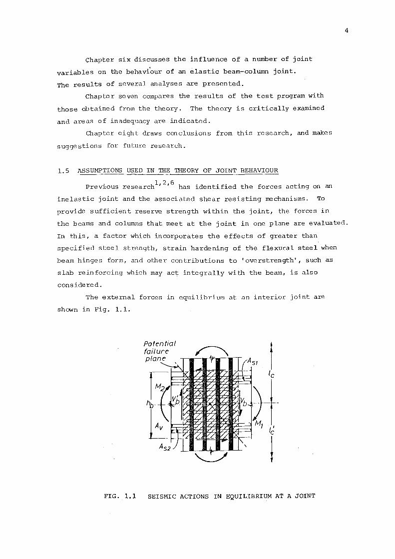
The external forces in equilibrium at an interior joint are
shown in Fig. 1.1.
FIG. 1.1
Potential failure plane
SEISMIC ACTIONS IN EQUILIBRIUM AT A JOINT
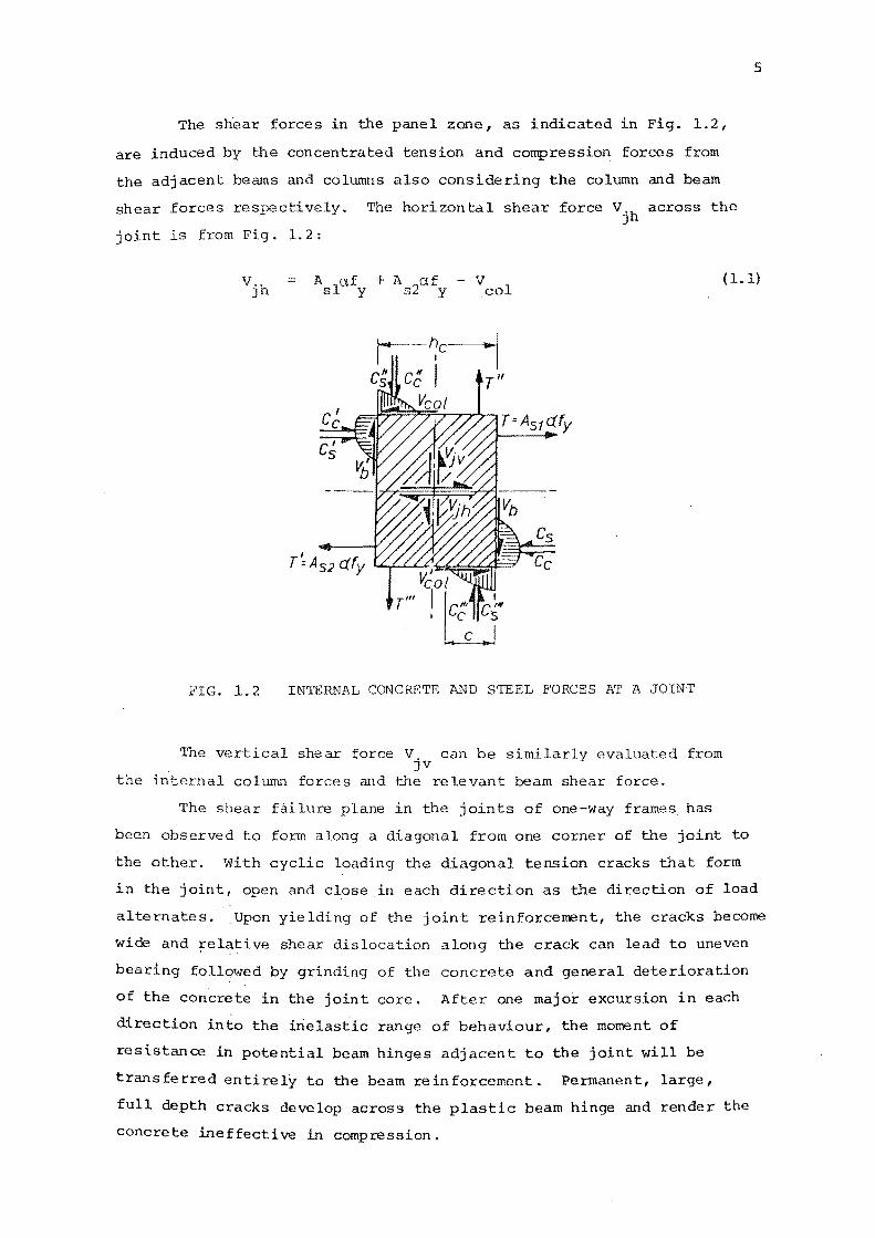
The shear forces in the panel zone, as indicated in Fig. 1.2,
are induced by the concentrated tension and compression, forces from
the adjacent beams and columns also considering the column and beam
shear forces respectively. The horizontal shear force Vjh across the
joint is from Fig. 1.2:
5
vjh A 1a.f + A {J,f - v { 1.1) col s y s y
~-~c---1 c; c~ I r"
c~ Veal
T=A51 afy
c~
FIG. 1.2 INTERNAL CONCRETE AND STEEL FORCES AT A JOINT
The vertical shear force V, can be simi evaluated from JV
the internal column forces and the relevant beam shear force.
The shear failure plane in the joints of one-way frames has
been observed to form along a diagonal from one corner of the joint to
the other. With cyclic loading the diagonal tension cracks that form
in the joint, open and close in each direction as the direction of load
alternates. Upon yielding of the joint reinforcement, the cracks become
wide and Felative shear dislocation along the crack can lead to uneven
bearing followed by grinding of the concrete and general deterioration
of the concrete in the joint core. After one major excursion in each
direction into the inelastic range of behaviour, the moment of
resistance in potential beam hinges adjacent to the joint will be
transferred entirely to the beam reinforcement. Permanent, large,
full depth cracks develop across the plastic beam hinge and render the
concrete ineffective in compression.
The shear transfer mechanisms in the panel zone may be idealised
as due in varying proportions to: diagonal strut action, truss action,
aggregate interlock, and dowel action. The diagonal compression force
creates a splitting force perpendicular to it, and reinforcing steel
is required to control the width of these cracks and to retain the
strength of the concrete compression field. The forces induced in the
panel zone by bond from the longitudinal reinforcement tend to be
transferred by the truss mechanism comprised of a number of diagonal
compression struts in the concrete, approximately parallel to the
potential failure plane, and of tension ties in the horizontal and
vertical planes. Usually, horizontal stirrup ties are provided to
resist the horizontal forces. The vertical strut components must be
resisted by intermediate bars, vertical stirrup ties, or special
vertical bars. A contribution from aggregate interlock may be expected
only where the cracks are narrow and the bearing surfaces are not worn.
For this a sliding displacement along a diagonal failure plane is also
necessary.
Dowel action in both the horizontal ties and the column bars
would also contribute to shear transfer, although this would only be
significant where the cracks are wide and the joint has deteriorated.
The contribution of the numerous, large diameter column bars to
horizontal shear transfer by the above mechanism could be significant
under these circumstances.
6
CHAPTER TWO
CODE REQUIREMENTS
The following codes and recommendations are examined, being
relevant to the seismic design of beam-column joints:
1. ACI 318-71 - Appendix A 3
7
2. ACI-ASCE Committee 352 "Recommendations for Design of Beam-Column
Joints in Monolithic Reinforced Concrete Structures" •1
3. N.Z.S. 3101 P: 1970 "Provisional Standard for Reinforced Concrete
Design". At present NZS 3101 P: 1970 is being revised, and
proposals pertaining to beam-column joints have been formulated
by a discussion group of the New Zealand National Society for
Earthquake Engineering (NZNSEE) •9 These proposals are likely to
be included in the new code.
4. P .w. 81/10/1 - May 1976 "Design of Public Buildings" draft . . 12
rev~s~on.
2.1 ACI 318-71 CODE ..,.. Appendix A ("Special Provisions for
Seismic Design")
The ACI code considers eccentrically loaded ductile members
in two categories. These are members with a design axial compression
(1) less than 40 per cent of the balanced ultimate load (0.4 Pb)
and (2) greater than 40 per cent of the balanced ultimate load.
If axial compression is greater than 0.4 ~, the following
requirements are applicable for confinement in columns:
(a) Hoop reinforcement shall be provided above and below connections
for a distance equal to the overall depth of the member, 450 mm,
or one sixth of the clear height of the column, whichever is the
greatest.
(b) The hoop steel shall have a volumetric ratio, Ps' not less than
=
or, =
A 0.45{ ~- }
ch
f I c
0.12 f y
f' c
f y (2.1)
(2.2)
with = (2. 3)
and the centre to centre spacing shall not exceed 100 mm.
If the axial load is smaller than 0.4 Pb, the column is required
to be designed and detailed as a flexural member, satisfying the
following requirements.
(a) Within a distance equal to four times the effective depth, d,
from the end of the member, the amount of web reinforcement
shall be not less than:
d s
= 0.15 A I s
or 0.15 A s
d whichever is the larger, and the spacing shall not exceed 4
(2. 4)
{b) When longitudinal bars are required to act as compression
reinforcement, stirrup ties spaced not further apart than 16 bar
diameters or 300 mm are required. Such ties at column ends shall
be provided for a distance of at least twice the effective depth,
d, from the column base.
8
For all axially loaded members, transverse reinforcement in the
columns must be provided to ensure that the shear capacity of the member
is at least equal to the applied shears at the formation of the plastic
hinge. The maximum spacing of shear reinforcement in columns shall be
d/2.
The ACI 318-71 code suggests that the nominal shear stress to be
carried by the concrete should be computed by:
However,
= N
0.166 ( 1 + 0.073 Au g
v shall not exceed c
(;. (MPa) c
v = 0.29 If' c c /1 + 0.29 :u (MPa)
g
The remainder of the shear must be carried by hoops, such that
=
and
=
v u
f A h d y s s
(2. 5)
(2 .6)
(2. 7)
(2. 8)
Beam-column joints in ductile frames shall have transverse
reinforcement proportioned from the above requirements with the design
shear in the connection computed by an analysis taking into account
the column shear and the shears developed from the yield forces in the
beam reinforcement.
2.2 ACI-ASCE COMMI~~EE 352
2.2.1 Joint Types
9
The recommendations for design of beam-column joints formulated
by Joint Committee 352 are classified into two categories in accordance
with the loading conditions for the joint:
Type 1: A joint for which the primary design criterion is strength
and no significant inelastic deformations are expected.
Type 2: A joint connecting members for which the primary design
criterion is sustained strength under reversals in the
inelastic range.
The forces in the flexual reinforcement at the interface between a
member and the joint shall be determined using the stress af • y
For type 1
For type 2
a> 1.0
a > 1.25
2. 2. 2 Strength Requirements
(a) Compression: The requirements for transverse reinforcement
in the joint are similar to those of ACI 318-71. That is, if
Pu > 0.4 Pb, then for confinement purposes the required area of
rectangular hoop reinforcement shall be computed by
A > 0 • 3 h" sh ( __<L - 1 )
Ach
which is similar to equation (2.1).
f I
c fll
yh (2.9)
Hoops shall be #3 (9.5 rom) bar minimum. For Type 1 joints,
confined by members on all four faces of the column, or on two opposite
faces, transverse reinforcement in the joint does ~ot need to be
provided in the direction of confinement; unless required for shear
strength, development of reinforcement, or for confinement of bars in
unconfined corners. The maximum spacing of ties in Type 1 joints
10
which require transverse reinforcement is 150 mm.
For Type 2 joints, minimum transverse reinforcement is required
such that,
A" sh
h"s h
> 0.12 f I
c f"
yh (2.10)
The centre to centre spacing of rectangular ties for all Type 2 joints
shall not exceed 100 mm.
(b) Shear: ACI-ASCE Committee 352 suggests that the nominal
shear stress shall be computed on the horizontal plane by considering
the horizontal shear forces on the boundaries of the joint and the
horizontal normal forces generated by tensile and compressive forces
in the beams framing into the joint, i.e. V . The nominal shear stress u
shall be computed by
v = v
u u A
cv
where A = the effective cross sectional area cv
(2.11)
The permissible shear stress carried by the concrete v in the joint c
shall not exceed the value given by the following equation
v c < 0. 29 s "(~I
c
N (1 + 0.29 u ) (MPa)
Ag (2.12)
(Note that for Type 2 joints it is recommended that N be taken as zero.) u
Depending on the degree of confinement available perpendicular
to the direction of shear forces being considered, that is if the
members cover at least three-quarters of the width and three-quarters
of the depth of the joint face, then y shall be equal to 1.4 otherwise
it shall be 1.0. For Type 1 joints S is taken as 1.4, and for Type 2
joints S = 1.0.
It is suggested that the nominal permissible shear stresses in
the concrete may exceed those formulated by ACI 318-71 and given as
equation (2 .6), when unidirectional static loading is applied to members
and only minimal ductility is required. Tests in which simulated
seismic loads were applied indicated that a satisfactory estimate of
the shear strength of the concrete is as given in equation (2.6).
11
Where the nominal shear stress, v , exceeds v , ties shall be u c
provided so that
(v - v ) A s A = v
u c cv f d y
(2.13)
Shear reinforcement placed less than s/2 or 25 mm from the
centroid of the concentrated tensile force generating shear shall not
be considered effective.
For Type 2 joints the transverse reinforcement shall provide
for not less than one third of the shear.
The value of v - v shall not exceed 1.25/fl (MPa) and in no u c c
case shall v be greater than 1. 66/f' (MPa) • u c
2.3 NZNSEE RECOMMENDATIONS
Only beam-column joints affected by seismic actions are
considered in these recommendations. The objective of the suggested
design requirements is to make the joint stronger than the adjacent
hinging members, and therefore to avoid significant inelastic behaviour
within the joint core.
The design shear forces acting on a beam-column joint are to
be evaluated from the maximum forces in all members acting at the
joint at flexural overstrength of the hinging members.
2.3.1 Horizontal Joint Shear
It is suggested that the nominal horizontal shear stress in
the joint vjh should not exceed 1.5~ (MPa), where
v.h V'jh = J
b, h J c
(2.14)
with b. J
taken as:
(a) when b > b c w
either b, = b J c
or b. = b + 0.5 h J w c whichever is the smaller.
(b) when b < b c w
either b. = b J w
or b. = b + 0.5 h J c c
whichever is the smaller.
The horizontal design shear force to be resisted by the
horizontal joint shear reinforcement should be
12
= (2. 15)
where vch is the allowable horizontal shear force carried by the
concrete shear resisting mechanism.
The value of Vch should be assumed to be zero except in the
following cases:
(a) When the minimum average corrpressive stress on the gross area
of the column above the joint, including prestress where
applicable, exceeds 0.1 f' c
f I /N f'
vch 0.25 (1 + c (b ,h } _9_ } ___E. -25 Ag 10 J c
( 2 .16}
(b) When all beams at the joint are detailed so that the critical
section of the plastic hinge is located at a distance of not
less than the depth of the member or 500 mm away from the
column face, then
v ch < A
s A'
s
N u
(l + 0.6 Afi g c
(2.17)
except that, where the axial column load results in tensile
stresses over the gross concrete area, the value of Vch should
be linearly interpolated between the value given by equation (2.17)
with N u
taken as zero, and zero when the axial tension stress is
0.2 f'. c
resisted
Thereafter the entire horizontal joint shear should be
by reinforcement.
The horizontal shear reinforcement should be capable of carrying
the design shear force assigned to the reinforcement, Vsh' across a
corner-to-corner diagonal tension crack plane. Therefore
where =
v sh
n fyh (2. 18)
cross sectional area of a set of multilegged
horizontal stirrup ties, and
n = number of sets.
13
The required horizontal sets of stirrup ties should be placed
between the outermost layers of the top and bottom beam reinforcement.
A horizontal stirrup tie should be placed adjacent to each layer of
beam flexural reinforcement, and other stirrup tie sets should be
distributed uniformly within the depth of the joint core.
2.3.2 Vertical Joint Shear
The vertical design shear force to be resisted by the vertical
joint shear reinforcement should be
v = V. v sv JV cv (2.19)
with A V. N
sc ___TI. (1 + u v = cv A' 2 0.6 A f I
(2.20) sc g c
Where axial tension stresses exist on the column then the value of V CV
is to be linearly interpolated in a similar fashion to that for
equation (2 .17) •
The vertical joint shear reinforcement should consist of
intermediate column bars, vertical stirrup ties, or special vertical'
bars placed in the column and adequately anchored to transmit the
required tensile forces within the joint.
The effective area of vertical joint shear reinforcement
should not be less than
L A. = JV
v sv
f yv
(2.21)
The spacing of column bars in each plane of any beams framing
into a joint should not exceed 200 mm, and in no case should there be
less than one intermediate bar in each side of the column in that plane.
2.3.3 Confinement
The horizontal transverse confinement reinforcement in
beam-column joints should not be less than that contained in reference
10, except that where the joint is adequately confined by beams on all
four column faces, with no potential plastic beam hinges at the column
face, this can be modified. In no case should the stirrup tie spacing
in the joint core exceed ten times the diameter of the column bar or
150 mm, whichever is less.
A summary of the applicable recommendations from reference 10
are given below.
The total area of hoop bars and supplementary cross ties
when p < e-0.6 f'A
c should be not less than
g
A f I p
s h" [ _3. - 1] c e ] (2.22) Ash = 0.3 f [ 0.33 + 1.67 f'A h A c yh c g
or f I p
Ash = 0.12 sh h" i-[0.33 + 1.67 fleA ] (2.23) yh c g
whichever is greater.
The minimum tie diameter is required to be not less than 8 mm.
The supplementary cross ties and legs of hoops should not be spaced
transversely more than either 200 mm or one-quarter of the column
section dimension perpendicular to the direction of the transverse
steel.
Each longitudinal column bar should be laterally supported by 0 the corner of a hoop having an included angle of not more than 135 ,
or by a supplementary cross tie, except where the distance between
two laterally supported bars does not exceed 200 mm between centres.
The yield force of the hoop bar or supplementary cross tie
should be at least one-sixteenth of the yield force of the bars it
is to restrain.
The spacing of hoop sets shall not exceed the smaller of
(a) one-fifth of the smaller column section dimension
(b) 150 mm
(c) six times the diameter of the longitudinal bar to be restrained.
2.4 "DESIGN OF PUBLIC BUILDINGS", PW 81/10/1
The design recommendations contained in this code of practice
tend to be stricter than those contained in the other codes and
recommendations listed. The suggested design procedure is similar
to that of reference 2 for seismic resistant joints, but a point of
interest are the recommendations for limits on size of bar.
To guard against a premature bond failure and slip of flexural
steel within the joint, it is recommended that for:
14
15
Beams ~< h /25 c f = 275 MPa y
Columns db< hb/25 f = 275 MPa y
" ~< ~/35 f = 380 MPa y
where ~ = diameter of bar,
h = depth of column member in direction of shear, and c
~ = depth of beam member in direction of shear.
2.5 SUMMARY OF RECOMMENDATIONS
The main differences in approach of the above recommendations are
summarised. For the purpose of joint design, the NZNSEE recommendations
suggest vertical joint shear should be considered as well as horizontal
joint shear. A method for determining the proportion of the shear force
resisted by the concrete in both directions is given.
The ACI-ASCE 352 and the ACI 318-71 approach, ignores vertical
shear and gives no indication that vertical shear reinforcement may be
required through the joint. ACI-ASCE 352 suggest that the design axial
load shall be taken as zero for Type 2 joints as the axial load is
influenced by overturning forces and vertical accelerations. The
NZSNSEE recommendations presented here also cover the evaluation of
column forces in reference 11 which indicates how axial load
effects should include the influence of probable beam overstrength
and possible magnification of column moments due to dynamic effects.
This reference provides methods for such evaluation. The ACI-ASCE 352
approach in this respect would appear to be conservative, especially in
the case of interior joints of large multistorey frames where net axial
tension is improbable.
ACI-ASCE 352 recommend that for Type 1 and Type 2 joints
the shear stress carried by the concrete may be increased by 40%,
where sufficient confinement is provided by members perpendicular to
the direction of the shear force. Whereas NZNSEE recommendations are
that, with potential plastic beam hinges near the column face,
confinement from the transverse members may not be relied on.
For confinement, the NZNSEE approach is that the amount of
transverse reinforcement required for a given section is dependent on
the axial load on the section. ACI-ASCE 352 suggest that for any given
section, the transverse reinforcement required should be
independent of the axial load.
16
CHAPTER THREE
ELASTIC JOINT MODEL
3.1 INTRODUCTION
This chapter reviews the analytical design proposals presented by
k d . 13 . .
Paulay, Par an Pr1estley, for elastic joints in a duct1le re1nforced
concrete frame experiencing severe seismic loading. The internal
concrete and steel forces at such an 'elastic' joint are shown in
Fig. 3.1 at the end of the chapter. The horizontal shear force
V across the J'oint is: jh
= A f +A I s s s
f I
s (3.1)
First it will be assumed that there is no axial load acting on
the column. The internal concrete compression forces, together with the
column and beam shears and bond forces 1 could form a system in equilibrium
within the joint core. This concrete mechanisms is shown in Fig. 3.2.
The principal component of the concrete mechanism is a diagonal concrete
strut, which transfers the force D between the corners of the joint c
core, and I::.T c
is the component of the total bond force to be
transferred within the joint core by the diagonal concrete strut.
This is expected to occur in the regions of transverse compression
supplied by the internal concrete forces.
As these internal concrete forces represent a significant
proportion of both the horizontal and vertical shear forces across the
joint, it is evident that a large part of the joint shear may be carried
by the above rrechanism. It is postulated that the shear resistance of
mechanisms associated with aggregate interlock forces along the diagonal
cracks and those with dowel shear across the reinforcement passing
through the joint are insignificant compared with the mechanism shown
in Fig. 3.2.
The possibility of aggregate interlock being significant has been
mentioned by some researchers based not on measurements but on known
beam action. But the system of forces in equilibrium at a joint differs
substantially from that occurring in beam action. Dowel action is
associated with larger shear displacements than those expected to occur
in an elastic joint, therefore, it is considered that this mechanism
should be neglected.
By considering the concrete forces in equilibrium at the lower
right-hand corner of the joint in Fig. 3.2, the horizontal component
of the diagonal compression force, D , can be defined as c
17
= C + !J.T - V c c col = D cos 6 c (3.2)
where ~T is the bond force transferred from the beam steel to the c
surrounding concrete within the shaded area of the strut. With the
remaining steel forces in equilibrium, large bond forces may be
introduced into the joint core. These bond forces will impart shear
stresses to the core concrete.
In most cases the diagonal tension capacity of the concrete in
the joint would be exceeded at relatively small loads as the tensile
splitting strength of the concrete is normally less than 10% of its
compressive strength. As the loads were increased it would be expected
that the resistance of the concrete against the shear forces introduced
by the longitudinal beam and column bars would break down.
If the joint core is suitably reinforced, with effectively
anchored horizontal and vertical steel, a truss mechanism can be
developed in which the confined core concrete supplies the necessary
diagonal compression field with a capacity of Ds. This truss mechanism
with the steel forces introduced by the be am and column bars is shown
in Fig. 3.3. With reference to Fig. 3.3, the part played by the tension
and compression members of the truss mechanism in resisting the shear
on the edge of the panel can be readily seen. It should be noted that
for this model with no vertical axial load acting, horizontal shear
reinforcement alone is not sufficient. A joint so reinforced does not
satisfy the basic requirements of equilibrium.
To maintain a diagonal compression field, such as in Fig. 3.3,
horizontal and vertical compression forces at the joint core boundaries
are required. Some codes1 ignore this concept of vertical equilibrium
and treat the problem of shear in beam-column joints as one of
horizontal equilibrium only. By viewing the maintenance of the diagonal
compression as a problem of horizontal and vertical equilibrium it
follows that either:
(a) Distributed horizontal and vertical reinforcement
effectively anchored at or beyond the boundaries
of the joint core is required,
or that
(b) External compression forces, such as gravity compression
on columns or central prestressing in beams, is required.
A practical solution is to use horizontal stirrup ties and
distributed vertical column bars placed so that they pass through the
joint core. It is emphasised that the vertical compression force
18
applied to the joint core by vertical joint reinforcement and compression
load on a column is as essential as the horizontal stirrup tie
reinforcement if the truss mechanism (Fig. 3.3) is to function.
It is convenient to denote the horizontal shear resistance
of this Jrechanism by
= = /::,.T s
= D cos f3 s
( 3. 3)
where /::,.T = C + T' - /::,.T (Fig. 3.3), is a bond force transmitted from s s c
the beam reinforceJren t to the core concrete of the truss mechanism.
Similarly the truss mechanism will sustain a vertical shear force V sv
From considerations of equilibrium and the recognition of a
potential diagonal failure plane across the joint, as shown in Fig. 1.1,
it is evident that horizontal shear reinforcement needs to be provided
so that
> vsh nf y
( 3. 4)
where n is the number of sets of multilegged stirrup ties, with a cross
sectional area of Ajh' that are uniformly distributed in the joint core
between the top and bottom beam reinforcement.
The vertical joint steel reinforcement should be capable of
sustaining, in addition to tensile loads that may be transmitted to
it from the columns, a tensile force of
v = D sin 8 sv s
3 · 2 THE ALLOCATION OF SHEAR STRENGTH TO 'IHE CONCRETE
AND SHEAR STEEL RESISTING MECHANISMS
(3.5)
For design purposes the relative proportion of the horizontal
shear, Vjh' that is resisted by the concrete mechanism, Vch (Fig. 3.2)
and by the truss mechanism, vsh' (Fig. 3.3) is required. The concrete
19
and steel shear mechanisms are assumed to be additive so that
= (3. 6)
To illustrate the relative magnitudes of the shear resisting
mechanisms based on the proposed concepts, a vector diagram (Fig. 3.4)
is used. The simple equilibrium requirements for the elastic joint are
also indicated on this diagram. With reference to Fig. 3.1, the
internal concrete and steel forces can be determined by elastic theory.
It is assumed for simplicity in this example that there is equal top
and bottom beam reinforcerrent provided (i.e. Asl = As2). The maximum
steel stresses are assumed to be close to but not exceeding yield,
and the resultant horizontal forces (Fig. 3.4) are those acting at the
level of the bottom reinforcement.
The ability of the joint to allow satisfactory bond transfer has
been recognised as an important aspect of joint performance. A rational
assumption of the bond stress distributions along bars passing through
the joint needs to be made. For the elastic joint a linear steel stress
variation and a corresponding uniform bond force distribution, u, is
assurred (Fig. 3.5). The cover concrete over the column bars on the
tension face is assumed to be unable to absorb transverse tensile
stresses.
A part (f>Tc) of the total steel force (T +C8
) (Fig. 3.4) will be
transmitted to the diagonal strut of the concrete shear resisting
mechanism. It {f>Tc} combines with the concrete compression force Cc
and the column shear V 1
, to develop, together with similar vertical co
internal column forcees, the principal diagonal compression force D c (Fig. 3.2). The remainder of the total horizontal steel force f>T
5 will
be part of the truss mechanism, shown in Fig. 3.3, which, when combined
with corresponding vertical bond forces from the column reinforcement,
will give rise to D • s
Fig. 3.4 combines these mechanisms and shows realistic relative
proportions of all forces discussed above. Previous research has
indicated that with negligible axial load on the column the concrete
shear resisting mechanism could account for over one half of the total
joint shear. The total diagonal force, D = D + D , remains constant c s
and proportional to the total joint shear to be resisted. As the joint
is elastic, also under cyclic loading, little degradation in the ability
of either mechanism to carry shear is expected. The relative proportions
of D and D should, however, change according to the level of axial c s
load acting on the joint.
3. 3 THE STRENGTH OF THE COMPRESSION FIELD
For the concrete to act as a satisfactory shear resisting
mechanism, limits on the diagonal compression to be carried are
necessary. This is to safeguard against a premature and possibly
20
sudden brittle compression failure of the concrete. The concrete struts
that form are bounded by dia~onal cracks in the core. They are subject i
to complex loading and distortions which would mean that the normal
crushing strength of the concrete could not be attained. When the
diagonal cracks form, the ties crossing the cracks have tensile strains
induced in them. As a consequence the tie imposes transverse tension
on the concrete strut bounded by two parallel cracks. The strut is thus
subjected to biaxial tension and compression. This is known to reduce 2
the unidirectional compressive strength of the concrete.
Limits on the value of the nominal joint shear stress are . . 1,3 normally spec1f1ed by codes to guard against overload of the
compression field. The appropriate limit for an elastic joint is
unknown at this stage. The elastic nature of the joint should enhance
the ability of the cracks formed under cyclic loading to close and bear
more evenly than in the corresponding inelastic case. Thus it would be
expected that the allowable nominal joint shear stress for elastic
joints could be higher than that applicable to joints behaving
inelastically.
3.4 THE EFFECT OF AXIAL LOAD
Axial compression is expected to increase the shear strength of
a beam-column joint. The simple mechanisms explained previously can be
extended to explain how axial compressive column load contributes to
shear resistance.
Fig. 3.1 shows (with dashed lines) that as a result of vertical
compression load on the column the neutral axis depth at the boundary
of the joint will increase to c*. As a consequence a larger proportion
of the develo[>ment of beam bars will be in the zone of transverse
compression (Fig. 3.5). Equilibrium considerations require that the
main diagonal compression force
an appropriate horizontal force
D * c (C
c
becomes steeper and that it engages
+ IJ.T *- V 1
> to maintain its c co
* inclination S • * Thus the share of the horizontal steel force b.T , c
that will combine with the total column compression stresses, must
become larger. Fig. 3.6 shows qualitatively the distribution of the
horizontal joint shear components Vch* and Vsh* with axial compression
p , while exactly the same beam moments are applied as in the previous u
21
example, shown in Fig. 3.4. Thus it can be seen that for the same beam
moment input, the higher the axial load the less joint shear
reinforcement will be required.
3.5 ADVANTAGES OF AN ELASTIC JOINT
Several advantages become apparent from this discussion on the
elastic joint model.
(a) As steel stresses at the boundaries of the joint do not
exceed yield, concrete strains are limited and hence the concrete
compression stresses are relatively lo'\o!.
(b) With inelastic behaviour adjacent to the joint,
permanent, large, full depth cracks develop across the plastic beam
hinge near the column face and render the concrete ineffective in
compression due to plastic elongation of the flexural reinforcing.
The moment of resistance in the beam hinges for the most part 'IVOUld be
provided only by the forces in the reinforcing steel. With an elastic
joint the concrete forces should not substantially diminish with cyclic
reversed loading as all tension cracks should close upon load reversal.
(c) As seismic loading is instantaneous, a substantial
proportion of the flexural compression force can be expected to be
transmitted by the concrete with no significant redistribution due to creep.
(d) As tensile yielding cannot occur, yield penetration,
interfering with the development of the required elastic strength of
the flexural reinforcement and efficient bond transfer, cannot take
place. Therefore the effective anchorage length of the beam bars is
likely to be maintained with more favourable bond conditions.
(e) The concrete compression forces, with an appropriate
proportion of the bond forces from the reinforcement passing through
the joint, can. combine to form a linear arch, D , similar to that shown c: 1 (t I 1.: ',.(II /
in Fig. 3.4. Due to the elastic nature of the j~lht the effectiveness
of this arch would not be expected to deteriorate even with cyclic
reversed loadi..'1g. The horizontal component of this arch, Vch' \·Thich
in part resists the total horizontal joint shear Vjh' could be
maintained.
(f) As a corollary to the above point, a smaller shear force,
V need be allocated to the truss mechanism. This means there would sh'
be a substantial reduction in the joint shear reinforcement required
compared with an inelastic joint, with a consequential lessening of
steel congestion in the joint core.
Analyses of elastic joints have indicated that when there is
no axial compression on the column, and equal top and bottom beam
flexural reinforcement is used, a little less than one half of the
horizontal joint shear need be carried by joint reinforcement,
i.e. Vsh < 0.5 Vjh" irt should be remembered, however, that the
contribution of other shear resisting mechanisms, that of dowel
action of the vertical column reinforcement in particular, has not
been considered in such analyses.
(g) In view of improved bond conditions in the joint region
and absence of yield penetration along the beam bars, size beam
bars could be used. Consequently a reduction in the number of bars is
possible. As the shear strength of such a joint is greater, the
flexural reinforcing content in the beams could be increased,
thereby enabling the use of shallower members.
22
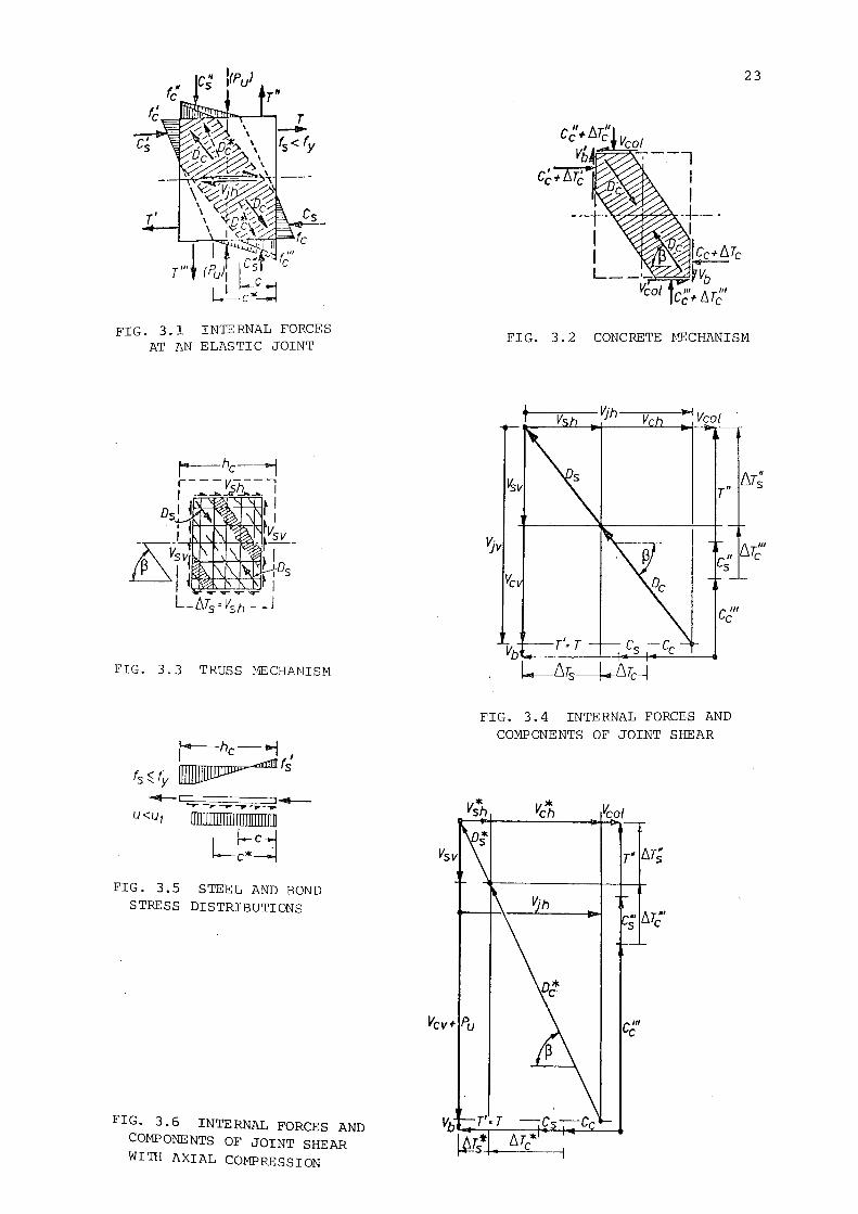
FIG. 3.1 INTERNAL FORCES AT AN ELASTIC JOINT
FIG. 3.3 TRUSS HECHANISM
....,...._c_,..~ .... ~-~--..;:-p~-..... ~~ U<u, ffilliiiii/IIIII!Illiillllll
L~~ FIG. 3.5 STEEL AND BOND
STRESS DISTRIBUTIONS
FIG. 3.6 INTERNAL FORCES AND COMPONENTS OF JOINT SHEAR WITH AXIAL COMPRESSION
23
FIG. 3. 2 CONCRETE MECHANISM
FIG. 3.4 INTERNAL FORCES AND COMPONENTS OF JOINT SHEAR
* Vsh
c'" c
CHAPTER FOUR
TEST PROGRAM
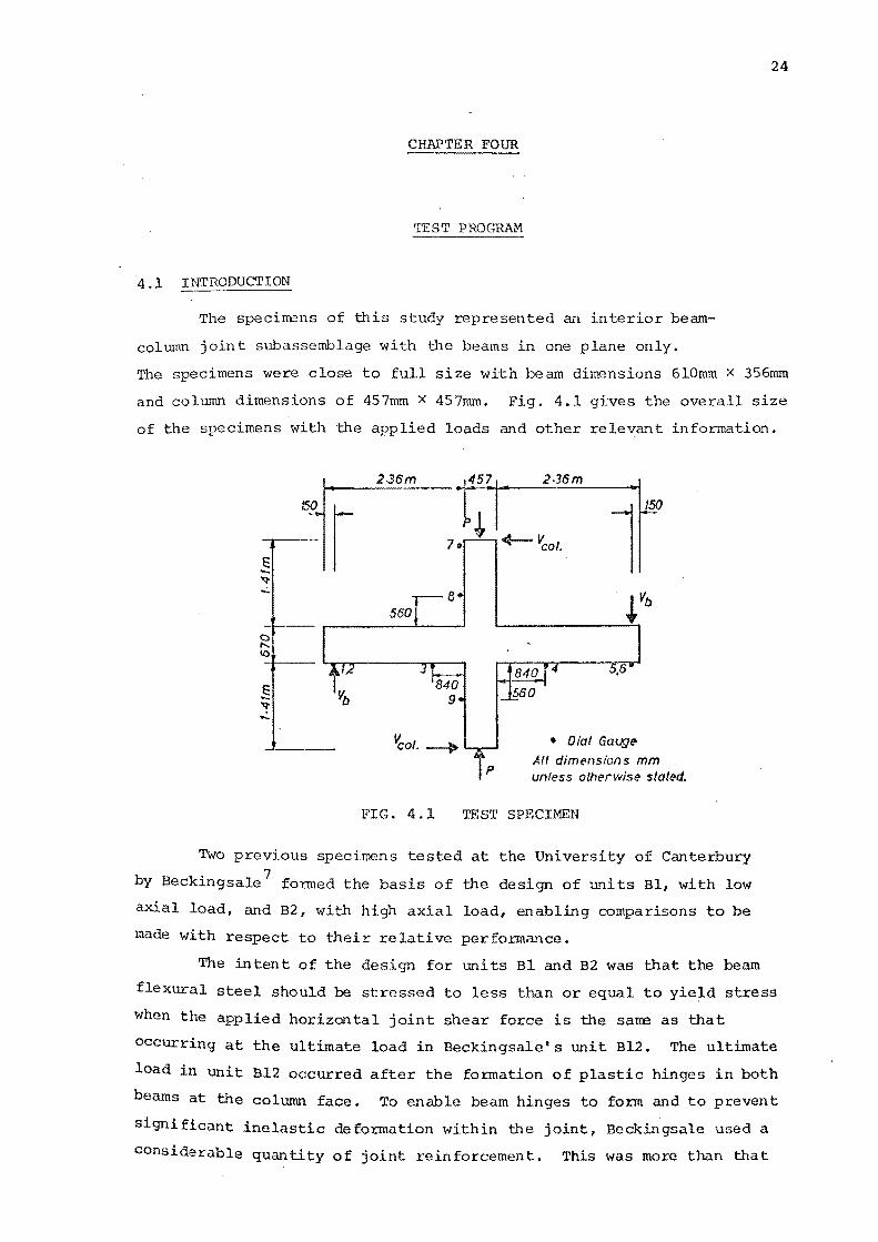
4.1 INTRODUcriON
The specimens of this study represented an interior beam
column joint subassemblage with the beams in one plane only.
24
The specimens were close to full size with beam dimensions 610mm x 356mm
and column dimensions of 457mm x 457mm. Fig. 4.1 gives the overall size
of the specimens with the applied loads and other relevant information.
2-36m
560
FIG. 4.1
457 2·36m
4-- ~of.
• Dial Gauge
All dimensions mm unless otherwise stated.
TEST SPECIMEN
Two previous specimens tested at the University of Canterbury
by Beckingsale 7 formed the basis of the design of units Bl, with low
axial load, and B2, with high axial load, enabling comparisons to be
made with respect to their relative performance.
The intent of the design for units Bl and B2 was that the beam
flexural steel should be stressed to less than or equal to yield stress
when the applied horizontal joint shear force is the same as that
occurring at the ultimate load in Beckingsale's unit Bl2. The ultimate
load in unit Bl2 occurred after the formation of plastic hinges in both
beams at the column face. To enable beam hinges to form and to prevent
significant inelastic deformation within the joint, Beckingsale used a
consid=rable quantity of joint reinforcement. This was more than that
25
suggested by ACI-ASCE Committee 352.1
The overall specimen performance
to be reported by Beckingsale, wassomewhat compromised by the slippage
of the beam steel.
As previously stated, a properly detailed plastic hinge
away from the column face can ensure that:
1. The beam flexural steel close to the joint is stressed below
yield when inelastic deformations are imposed on the structure,
thus reducing the danger of bar slip in the joint.
2. With the inelastic defonnations restricted to the hinge region,
the joint should largely deform within its elastic limits,
provided that there is no substantial spread of yield from
the hinge region.
Beckingsale's units B12 and Bl3 had identical beam flexural
steel contents, i.e. p = P' = 0.0086 = 0.175 Pb· An axial load of
311 kN (= 0.046 P0 ) was applied to unit Bl2, and 8 sets of 4 legs
of 12.7 mm joint ties were provided assuming ·that they would carry the
entire horizontal design joint shear force. Unit Bl3 carried initially
a column load of 2890 kN (= 1.32 Pb = 0.43 P0 ) and contained only 6 sets
of 4 legs of 12.7 mm ties for joint reinforcement. This reduction in
joint shear reinforcement was made to take into account the increased
capacity of the concrete to carry shear under high axial load.
Unit Bl2 was loaded cyclically and with stepwise increases
a maximum displacement ductility of six was attained. The joint core
maintained its integrity in the test, and plastic hinges formed in
the beams near the column face. Slip of the beam steel caused severe
stiffness degradation when large displacement were applied, but
little load degradation was observed.
Unit Bl3 was loaded to D.F. 6 at a column load of 2890 kN
(0.43 P0
) and as the specimen performed well, the axial load was
subsequently lowered to 1680 kN (0.25 P ) with further inelastic 0
load cycles being applied up to a displacement ductility of 6.
The lowering of axial load, although accompanied by larger stiffness
deterioration, did not affect the good performance of the specimen.
Detailed calculations for the test specimens Bl and B2 are
given in Appendix A. However, a summary of the reinforcement used
is given in the following sections.
4. 2 THE BEAMS OF UNITS B 1 AND B2
* The theoretical ultimate beam moment {M. ) , based on a steel u
couple, for Beckingsale's unit Bl2 was 256 kN-m. The observed
ultimate moment applied during the test was 321 kN-m. This was
based on the average of ultimate beam tip loads applied to both beams.
This corresponds with an overstrength factor ¢ of 1.25, due to strain 0
hardening of beam steal.
It was intended that units Bl and B2 should have a maximum
applied moment, similar in magnitude to the moment at overstrength
26
{M 0) in Beckingsale's unit Bl2. The moment at the elastic limit {M *>
u y was defined as the moment causing yield of the tension reinforcement
at the column face. An elastic analysis of the beam section indicated ' * that 8-020 reinforcing bars {p = p' = 0.013) were required with M
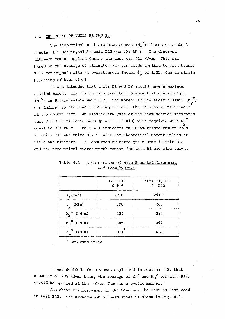
y equal to 334 kN-m. Tahle 4.1 indicates the beam reinforcement used
in units Bl2 and units Bl, B2 with the theoretical moment values at
yield and ultimate. The observed overstrength moment in unit Bl2
and the theoretical over strength moment for unit Bl are also shown.
Table 4.1 A Comparison of Main Beam Reinforcement and Beam Moments
Unit Bl2 Units Bl, B2 6 # 6 8-020
As {mm2) 1710 2513
f y
{MPa) 298 288
My* {kN-m) 237 334
* {kN-m) Mu 256 347
Muo 1
{kN-m) 321 434
1 observed value.
It was decided, for reasons explained in section 4.5, that
a moment of 288 kN-m, being the average of Mu* and Mu0 for unit Bl2,
should be applied at the column face in a cyclic manner.
The shear reinforcement in the beam was the same as that used
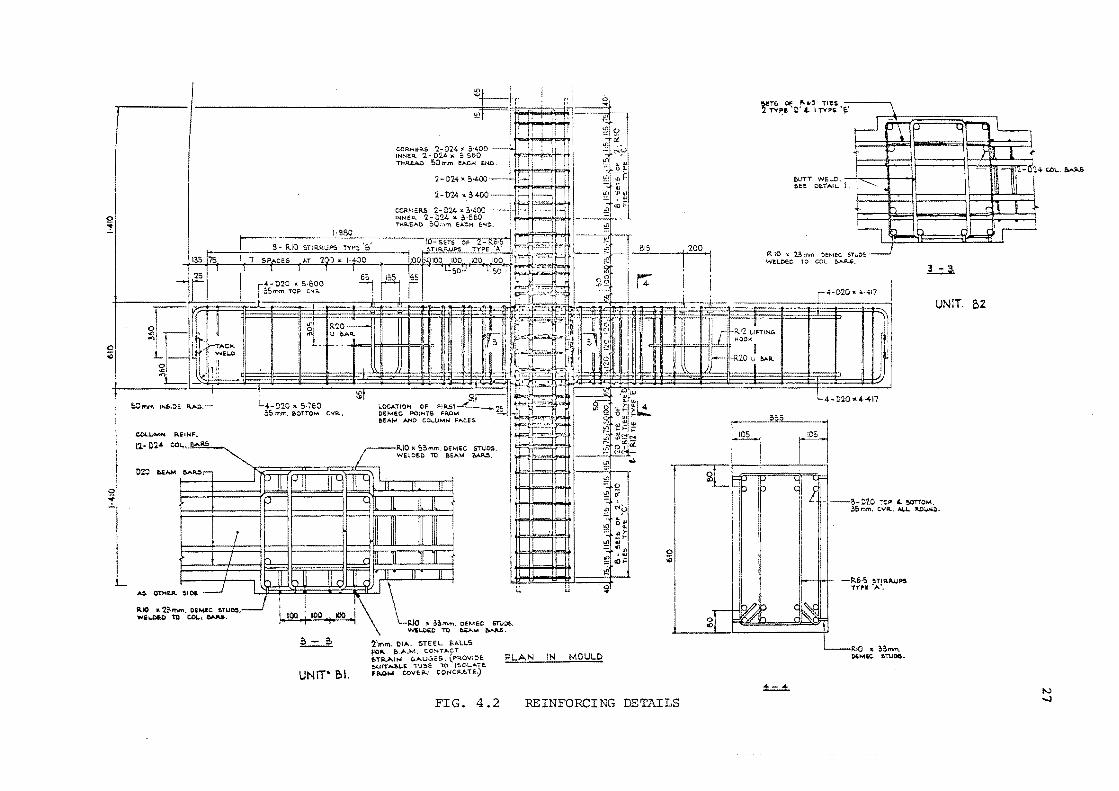
in unit Bl2. Th f 1 · h · · 4 2 e arrangement o beam stee ~s s own ~n F~g. • .
0
~
~,
50mm IN.Sl::>E
RlO :a, 2~mm. OEII4t: ftTU~. WE~D To CQL., .........
1·980
L,_ D20 • 5·760 55 tnrr:, &OTTOM C.VR.-.
~
UNIT• Bl.
COI>.NEP..S 'l- 024' 3·400 INNt:R. '2.- 024 :K ~·500 THR.EAO 50 tr.m. !ACH ENO.
R.IO ' So mm. O£MEC sruos. WEI..-OEC TO &EA..,. M~.
~ .. IUO • !!mm. OEMEC STUDS. '" '>N'EUl£0 TO ~M ~-
~[1!\Jn. I)IJ>.. !>TEEL !l.ALLS
~~0 ~ " - ' ~ ~!->
"'l:!;::: - "')-...... "' "' = 4llol) Ill • ~ :;;;::: «H-)!!
" 0 u •
0 ;Q
fOR. &.A.M. C.O~TACT t•TAA~N ""uG£S. (P'<OVIOE PLAN IN MOULD S.U\T-'l>I..E TUbE: 'TO- !SOL.AT£ F~M COVEl'-< CONCP..,_TE~
FIG. 4.2 REINFORCING DETAILS
0
"'
r~P::IY"'t'1 ;_•;;.E.'
llUTT WE~O. ' c I .. SEE CE.TAiL.
rt :0 'II. 23 mm OEM!:C $T;;05 W£1..0EC TO COL &AP-.$.
L4- ~:1.0 "4·417
.L::.J:.
UNIT BZ
-•--B-::20 ~~P 4 !>OT"J'OM. ~Sr:vn. C:.VIil, AI..L. ..O_,)olQ:.
±..=...±.
-R.&·S ~TIRJI..UP:II TYII'l ·;..•
!amm. tlf;MiC &TUQ6.
N ...:!
~
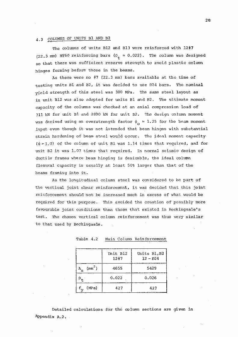
4.3 COLUMNS OF UNITS BlAND B2
The colrnnns of units Bl2 and Bl3 were reinforced with 12#7
(22.3 rom) HY60 reinforcing bars (pt = 0.022). The column was designed
so that there was sufficient reserve strength to avoid plastic column
hinges forming befol~ those in the beams.
As there were no #7 {22.3 rom) bars available at the time of
testing units Bl and B2, it was decided to use D24 bars. The nominal
yield strength of this steel was 380 MPa. The same steel layout as
in unit Bl2 was also adopted for units Bl and B2. The ultimate moment
capacity of the columns was checked at an axial compression load of
311 kN for unit Bl and 2890 kN for unit B2. The design column moment
was derived using an overstrength factor ¢0
1.25 for the beam moment
28
input even though it was not intended that beam hinges with substantial
strain hardening of beam steel would occur. The ideal moment capacity
(¢ 1.0) of the column of unit Bl was 1.14 times that required, and for
unit B2 it was 1.07 times that required. In normal seismic design of
ductile frames where beam hinging is desirable, the ideal column
flexural capacity is usually at least 50% larger than that of the
beams framing into it.
As the longitudinal column steel was considered to be part of
the vertical joint shear reinforcement, it was decided that this joint
reinforcement should not be increased much in excess of what would be
required for this purpose.. This avoided the creation of possibly more
favourable joint conditions than those that existed in Beckingsale's
test. The chosen vertical column reinforcement was thus very similar
to that used by Beckingsale.
Table 4.2 Main Column Reinforcement
unit Bl2 Units Bl ,B2 12#7 12- D24
A (mm2.) 4655 5429 s
pt 0.022 0.026
fy (MPa) 427 427
Detailed calculations for the column sections are given in
Appendix A.2.
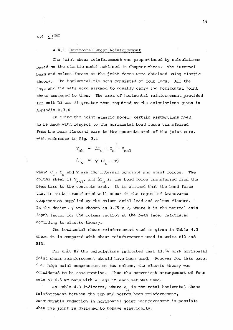
4.4 JOINT
4.4.1 Horizontal Shear Reinforcement
The joint shear reinforcement was proportioned by calculations
based on the elastic model outlined in Chapter three. The internal
beam and column forces at the joint faces were obtained using elastic
theory. The hqrizontal tie sets consisted of four legs. All the
29
legs and tie sets were assumed to equally carry ~~e horizontal joint
shear assigned to them. The area of horizontal reinforcerrent provided
for unit Bl was 8% greater than required by the calculations given in
Appendix A. 3. 4.
In using the joint elastic model, certain assumptions need
to be made with respect to the horizontal bond force transferred
from the beam flexural bars to the concrete arch of the joint core.
With reference to Fig. 3.4
vch /J.T + c - v c c col
!J.T c = y (C + T)
s
where C , C and T are the internal concrete and steel forces. The c s column shear is V
1, and !J.T is the bond force transferred from the
co c beam bars to the concrete arch. It is assumed that the bond force
that is to be transferred will occur in the region of transverse
compression supplied by the column axial load and column flexure.
In the design, y was chosen as 0.75 x k, where k is the neutral axis
depth factor for the column section at the beam face, calculated
according to elastic theory.
The horizontal shear reinforcement used is given in Table 4.3
where it is compared with shear reinforcement used in units Bl2 and
Bl3.
For unit B2 the calculations indicated that 13.5% more horizontal
joint shear reinforcement should have been used. However for this case,
i.e. high axial compression on the column, the elastic theory was
considered to be conservative. Thus the convenient arrangement of four
sets of 6.5 mm bars with 4 legs in each set was used.
As Table 4.3 indicates, where ~ is the total horizontal shear
reinforcement between the top and bottom beam Leinforcement,
considerable reduction in horizontal joint reinforcement is possible
when the joint is designed to behave elastically.
30
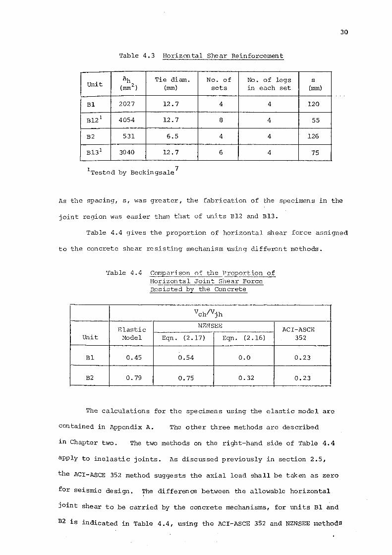
Table 4.3 Horizontal Shear Reinforcement
Ah Tie diam. No. of No. of legs s Unit (mm2) (mm) sets in each set (mm)
Bl 2027 12.7 4 4 120
Bl2 1 4054 12.7 8 4 55
B2 531 6.5 4 4 126
Bl3 1 3040 12.7 6 4 75
1Tested by Beckingsale7
As the spacing, s, was greater, the fabrication of the specimens in the
joint region was easier than that of units Bl2 and Bl3.
Table 4.4 gives the proportion of horizontal shear force assigned
to the concrete shear resisting mechanism using different methods.
Unit
Bl
B2
Table 4.4 Comparison of the Proportion of Horizontal Joint Shear Force Resisted by the Concrete
vch/Vjh
Elastic NZNSEE
Model Eqn. (2.17) Eqn. (2 .16)
0.45 0.54 0.0
0.79 0.75 0.32
ACI-ASCE 352
0.23
0.23
The calculations for the specimens using the elastic model are
contained in Appendix A. The other three methods are described
in Chapter two. The two methods on the right-hand side of Table 4. 4
apply to inelast:ic joints. As discussed previously in section 2.5,
the ACI-ASCE 352 method suggests the axial load shall be taken as zero
for seismic design. ~he difference between the allowable horizontal
joint shear to be carried by the concrete mechanisms, for units Bl and
B2 is indicated in Table 4. 4, using the ACI-ASCE 352 and NZNSEE methods
for inelastic joints. Also shown is the enhanced shear resistance,
implied by two methods, as being provided in an elastic joint
compared with that implied for inelastic joints.
4.4.2 Vertical Joint Shear Reinforcement
31
As suggested in Chapter three vertical joint shear reinforcement
might be required to complete the truss mechanism. The elastic model
suggests that vertical joint reinforcement or vertical axial compression
should be capable of sustaining, in addition to loads transmitted to
the joint from column flexure, a tensile force of
where D is the diagonal component of the truss mechanism, with an s
inclination of angle B to the horizontal.
A conservative approach appears to be to assign all the vertical
tension from the above equation to intermediate bars spaced along the
perimeter of the column section in the plane of the applied shear.
This would ignore the effect of axial compression on the column,
restraining vertically the truss mechanism. However, previous
research 15 '~ on the behaviour of beam-column joints with low axial
load, indicates that without intermediate bars, joint behaviour can
be unsatisfactory.
Calculations for vertical reinforcement are also contained in
Appendix A where it is assumed the intermediate bars only, act
with the column axial load to sustain V sv
For the case of the high axial load (unit B2), the calculations
indicate that no vertical joint shear reinforcement is required. In
unit Bl it is fotmd that the intermediate bars are adequate for
vertical shear steel.
4. 4. 3 Confinement
In many situations for seismic design the full benefits of an
elastic joint will not be utilized due to the confinement requirements
of various codes. These may require more horizontal stirrup-tie
reinforcement than that required for shear resistan03.
4.5 LOADING SEQUENCE
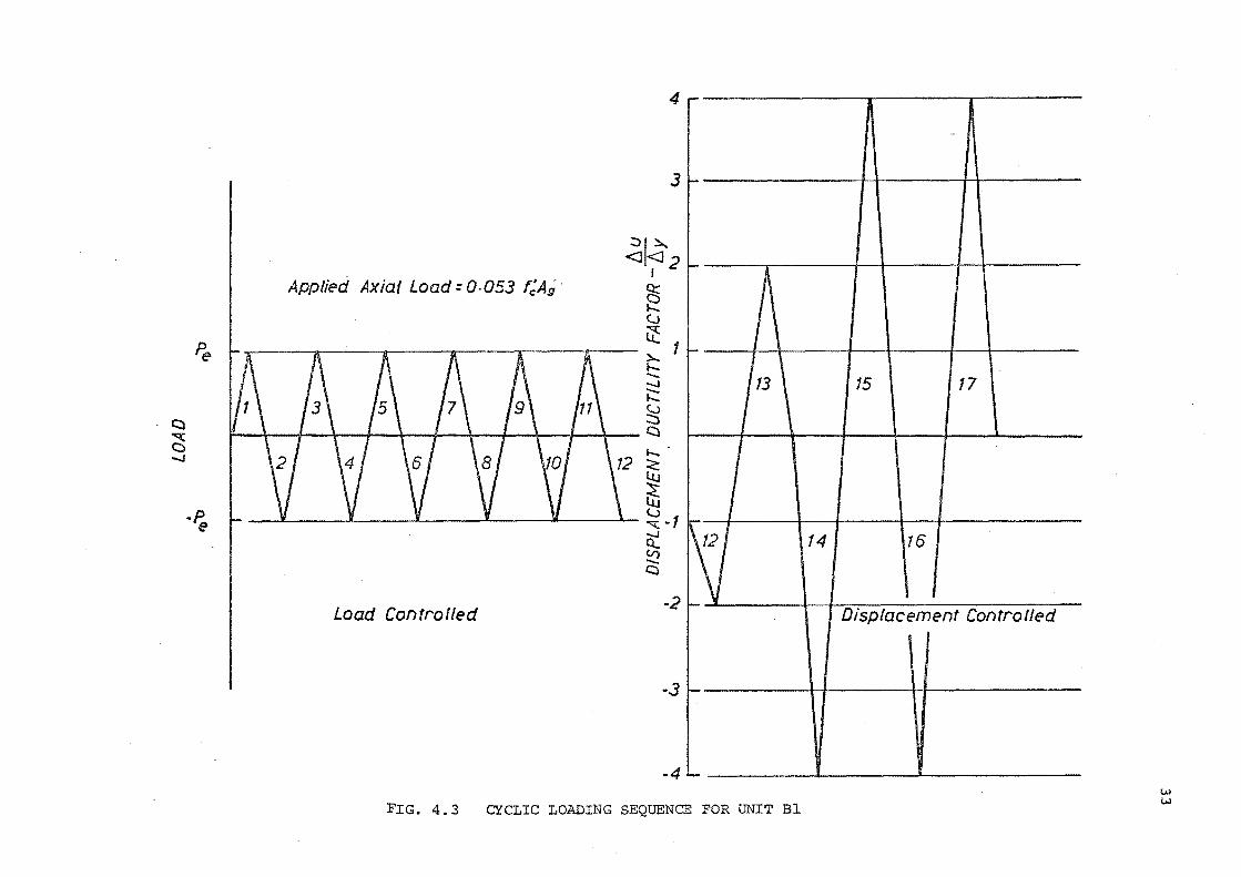
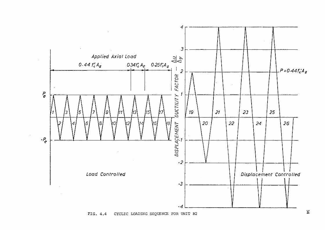
The loading sequence for the two units is shown in Figs 4.3
and 4.4. For unit Bl twelve load cycles at the elastic limit P e
were applied. A cycle being defined as from zero load to maximum load
or under displacement control to maximum displacement, then back to
zero. The theoretical elastic limit, as previously described in
section 4.2, was determined to be an applied beam shear of 151 kN
* (M = 334 k.Nm). Initially it was proposed to load the beams up to y
150 kN but when the beam shear applied in the first cycle of unit Bl
reached 135 kN it was observed that yield of the outer layer of beam
reinforcement had occurred, the highest strains being measured in the
region of the outer column bars. Some possible reasons for the
inability of the elastic theory to satisfactorily predict the onset
of yielding are given below.
The beam bars that are crossed by column bars are influenced by
transverse tensile stresses,and strain peaks in this region are not 14
surprising. They ha.ve been observed by other researchers. .
The exactness of using a straight-line strain distribution at the
column-beam interface may be questioned because of the possibility
of end-effects that may bring about a non-linearity of the strain
profile. The modular ratio, n, chosen for the calculations was based . 3 . on ACI practice but it could have been different.
This observed yielding of beam steel was not considered to be
important as the elastic nature of the joint was preserved. The inner
layer of bars would certainly not have yielded. The beam tip load
which was subsequently applied for the rest of tl1e elastic cycles,
in units Bland B2, was 130 kN.
After the completion of the elastic cycles in unit Bl, one
cycle in each direction was applied at a displacement ductility factor
of 2, followed by two cycles in each direction at a displacement
ductility factor of 4. The displacement ductility factor being
defined, in these tests, as the ratio of the vertical displacement at
the end of the beam, to that occurring from extrapolation of the
measured load-deflection curve to the theoretical ultimate load. The
axial column load on unit Bl was kept constant at 311 kN (0.053 f 'A ) c g
throughout the teBt.
Unit B2 was loaded with twelve reverse cycles at the chosen
elastic limit of 130 kN with an applied axial compression of 2890 kN
(0.44 f 'A ) • The joint was lightly reinforced and it was felt that c g
32
4 .-
3 1-
::>,~
<J<J2
Applied Axial Load= 0.053 t;A; I
g§ h. (J
Pe t-11 ~
J\ II 1\ A A ~ 1 .._ -....... -.._ Cl
I' ~ I ~ I \ I \of ~ _l \
§i Cl ""'( \')/ \A I \~1 \4n/ \ 4'l ~ 0
.......
Lu
~ -P.. ~ y ~ )t I v l lJ
e ""'( -1
5 0
Load Controlled -2
f-
I f- I \
113' I
~ j If) 1-
-.3 1-
-4 I...
FIG. 4.3 CYCLIC LOADING SEQUENCE FOR UNIT Bl
15 17
'
14 16
I I Displacement Controlled
w w
~
-~
Applied Axial Load
o.44 r:Ag. 034f~ Au
4
3
::,I~ 0·25t:A <J <J c g
12 Q:::
2 (..)
~ )..... 1 .._
I ' I -' \ I ' _, ' ' ' -I \ ,_ l \ I ~ \ ' \ a I
Load Controlled
.._
~ lJJ t..>-1
""' ct ~ a
-2
-3
-4
r-
f-
~A
~19 \ \20
f.-
v !-
-
-FIG. 4.4 CYCLIC LOADING SEQUENCE FOR UNIT B2
p =0-44
21 23 25
22 24 26
Displacement Controlle I I I
fc'Ag
d
w J;::o.
lowering the axial load to 0. 25 f 1 A might cause yield in the joint c g
ties to occur. Therefore the column load was lowered to only 2240 kN
(0.34 f 1 A). After two cycles at the elastic limit little increased c g
joint deterioration had occurred, with only a marginal increase in
joint tie strain. Therefore, four further cycles were applied at the
elastic limit with an axial load of 1645 kN (0. 25 f 1 A ) • With this c g
the initial objectives of the planned test were met. Subsequenhly
35
the axial load was raised to 2890 kN and inelastic cycles were imposed.
Two cycles at displacement ductility factor of two were followed by
six cycles at displacement ductility factor of four.
Testing of unit Bl required nine days, while that of unit B2
required eight days. On average, three cycles were completed in a day
although the rate of testing was dependent on whether the cycles were in
the elastic or inelastic range.
4.6 MATERIAL PROPERTIES
4. 6. 1 Concrete
The concrete used in both test specimens consisted of 12 mm
aggregate. A 75 nun slump and a minimum crushing strength of 28 MPa
at 28 days was specified.
Actual concrete crushing strengths were obtained from tests on
standard 12" X6" (304.8 mm x 152.4 mm) cylinders. The concrete
cylinders were from the batch concrete placed in the joint core and
they were cured along with the specimen. The average of six compression
tests, taken at the start of specimen testing, is listed in Table 4.4.
4.6.2 Steel
The beam and column longitudinal reinforcement consisted of
deformed bars while all transverse shear reinforcement consisted of
plain bars. All steel bars of a particular size were taken from the
same batch.
Three samples of each size of bar were tested in tension to
determine the yield and ultimate strengths. The average results of
these samples are listed in Table 4.4.
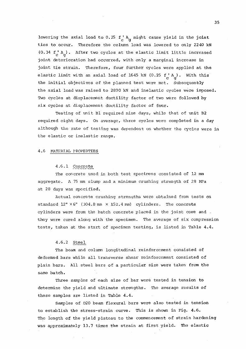
Samples of D20 beam flexural bars were also tested in tension
to establish the stress-strain curve. This is shown in Fig. 4.6.
The length of the yield plateau to the commencement of strain hardening
was approximately 13.7 times the strain at first yield. The elaBtic
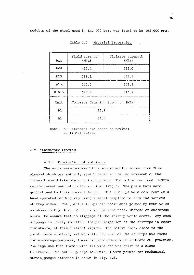
modulus of the steel used in the D20 bars was found to be 192,000 MPa.
Table 4.4 Material Properties
Yield strength Ultimate strength Bar (MPa) (MPa)
D24 427.4 731.0
020 288.1 448.8
!" <I> 345.5 449.7
R 6.5 397.8 514.7
Unit Concrete Crushing Strength (MPa)
Bl 27.9
B2 31.5
Note: All stresses are based on nominal sectional areas.
4. 7 LABORA'IORY PROGRAM
4.7.1 Fabrication of specimens
36
The units were prepared in a wooden mould, formed from 20 mm
plywood which was suitably strengthened so that no moverrent of the
formwork would take place during pouring. The column and beam flexural
reinforcement was cut to the required length. The plain bars were
guillotined to their correct length. The stirrups were cold bent on a
hand operated bending rig using a metal template to form the various
stirrup sizes. The joint stirrups had their ends joined by butt welds
as shown in Fig. 4.2. Welded stirrups were used, instead of anchorage
hooks, to ensure that no slippage of the stirrup would occur. Any such
slippage is likely to effect the participation of the stirrups in shear
resistance, at this critical region. The column ties, close to the
joint, were similarly welded while the rest of the stirrups had hooks
for anchorage·purposes, formed in accordance with standard ACI practice.
The cage was then formed with tie wire and was built to a close
tolerance. The built up cage for unit Bl with points for mechanical
strain gauges attached is shown in Fig. 4.5.
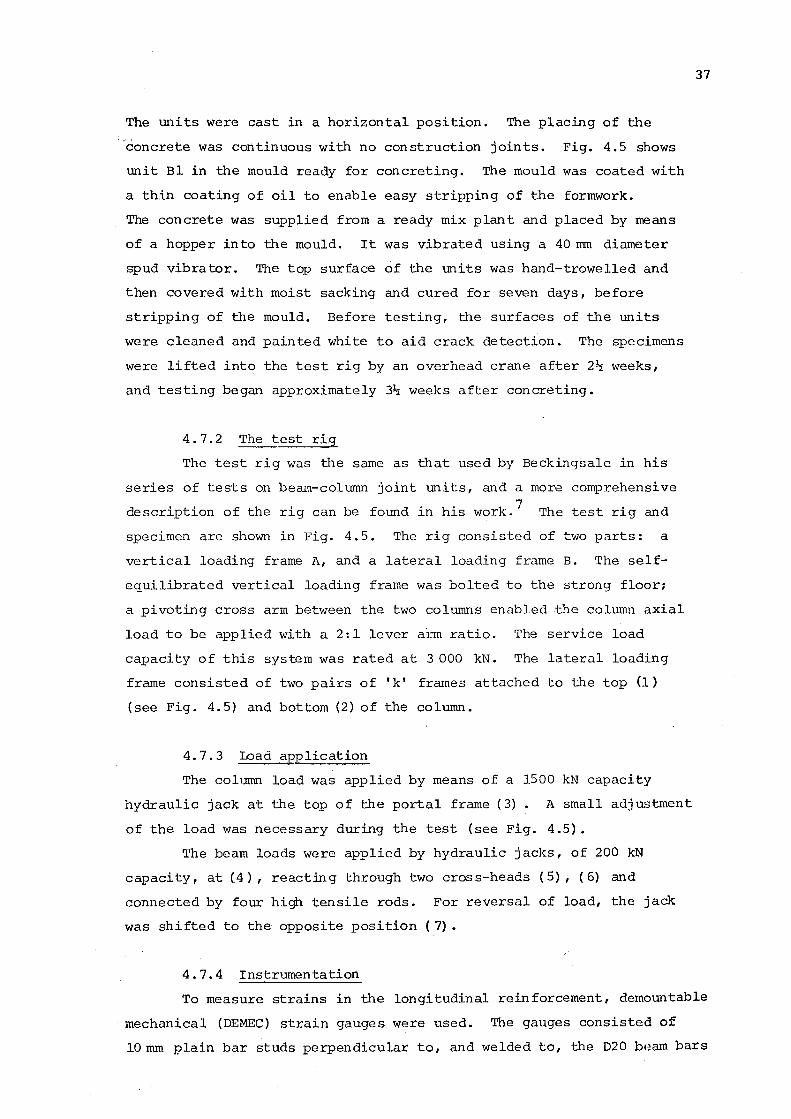
The m1its were cast in a horizontal position. The placing of the
concrete was continuous with no construction joints. Fig. 4.5 shows
unit Bl in the mould ready for concreting. The mould was coated with
a thin coating of oil to enable easy stripping of the formwork.
The concrete was supplied from a ready mix plant and placed by means
of a hopper into the mould. It was vibrated using a 40 nun diameter
spud vibrator. The top surface of the units was hand-trowelled and
then covered with moist sacking and cured for seven days, before
stripping of the mould. Before testing, the surfaces of the units
were cleaned and painted white to aid crack detection. The specimens
were lifted into the test rig by an overhead crane after 2~ weeks,
and testing began approximately 3~ weeks after concreting.
4. 7. 2 The test rig
The test rig was the same as that used by Beckingsale in his
series of tests on beam-column joint units, and a more comprehensive
description of the rig can be found in his work. 7 The test rig and
specimen are shown in Fig. 4.5. The rig consisted of two parts: a
vertical loading frame A, and a lateral loading frame B. The self
equilibrated vertical loading frame was bolted to the strong floor;
a pivoting cross arm between the two collli~S enabled the column axial
load to be applied with a 2:1 lever arm ratio. The service load
capacity of this system was rated at 3 000 kN. The lateral loading
frame consisted of two pairs of 'k' frames attached to the top (1)
(see Fig. 4.5) and bottom (2) of the column.
4.7.3 Load application
The column load was applied by means of a 1500 kN capacity
hydraulic jack at the top of the portal frame ( 3) . A small adjustment
of the load was necessary during the test (see Fig. 4.5).
The beam loads were applied by hydraulic jacks, of 200 kN
capacity, at (4), reacting through two cross-heads ( 5), ( 6) and
connected by four high tensile rods. For reversal of load, the jack
was shifted to the opposite position (7).
4.7.4 Instrumentation
37
To measure strains in the longitudinal reinforcement, demountable
mechanical (DEMEC) strain gauges were used. The gauges consisted of
10 mm plain bar studs perpendicular to, and welded to, the D20 bHam bars
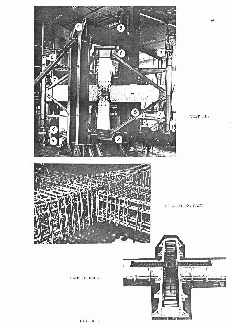
38
TEST RIG
REINFORCING CAGE
CAGE IN MOULD
FIG. 4.5
39
and the D24 column bars. The studs were set flush to the concrete
surface. The studs were isolated from the cover concrete by enlarged
holes formed by plastic tubing. DEMEC points, consisting of stainless
steel buttons indented with a small hole, were attached with sealing wax
to the end of the studs. A 4" (101.6mm) gauge length was used and nine
gauge lengths along the outer beam bar, both at the top and bottom of
the beam, were used as shown in Fig. 4.2.
DEMEC gauges were similarly used to measure strains in all the
column bars passing through the joint on one faceonly. Nine gauge
lengths were used as indicated in Fig. 4.2.
The strains on the outer legs of the main ties were recorded by
the use of a BAM mechanical contact strain gauge which uses steel balls
pressed into the surface of the steel as targets for the gauge lengths.
(see Fig. 4.2). These small, hardened balls were set into the tie by
a special punch. A thin cylindrical steel tube was placed around the
steel balls and tack welded to the ties. A plastic tube was placed
over this steel tube to isolate it from the cover concrete, and
subsequently removed after casting, to provide an enlarged hole. The
strain gauge was hand held and mechanically operated.
Displacements in the beam and column were measured by dial gauges
graduated in 0.01 mm divisions, with a travel of 50 mm.
Vertical displacements in the beam, in the plane of bending,
were measured by a pair of dial gauges at the ends of both beams.
A dial gauge was also located 840 mm away from the column face on the
two beams. The dial gauges were attached to a rigid stand mounted on
the floor.
Horizontal column displacements, in the plane of bending, were
measured by a dial gauge situated 560 mm away from the top of the beam
and 560 mm away from the bottom of the beam. The dial gauge locations
are indicated in Fig. 4.1. Measurements of the movement of the test rig
were made using a dial gauge at the top of the rig.
An accurate measurement of the column load applied by the
hydraulic jack, was made using a 1500 kN load cell monitored by a
Budd strain bridge. Calibration of the load cell was made prior to
testing, with a 560,000 lb (2,~500 kN) Avery Universal testing Machine.
The beam loads wer= measured by a 200 kN load cell similarly monitored
by the strain bridge.
40
A continuous record of the load-displacement characteristics of
both beams was produced by two Hewlett-Packard X-Y plotters. This
recorded the vertical beam load applied at the end and the vertical end
displacement of the beam. The beam load was measured by connecting
the plotter in series to the load cell.
Calibration of the plotter for load was achieved by connecting
the plotter in series with the Budd strain bridge, the load cell, and
the testing machine. LVDT' s {Linear Variable Displacement Transducers)
driven by a constant voltage power source were used to measure the
vertical beam displacements for the plotter. Calibration of the LVDT
to the plotter was achieved by using a micrometer with a 20 mm
extension.
4.7.5 The testing procedure
At the start of the test the column load was applied by means
of a hand pump connected to the hydraulic jack. Three sets of readings
of all the dial gauges, DEMEC gauges and BAM contact strain gauges
were taken before application of beam loads. Beam loads were applied
using hand pumps connected to the hydraulic jacks. The load applied
to the beam was monitored by the Budd strain bridge, and three
increments were normally applied before the intended maximum load in
the cycle, at the elastic limit P , was reached. Adjustment of the e
column load was made after each increment. At each increment, dial
gauge readings were taken and on some load cycles a complete set of
strain readings was taken for the beam and column bars, and the joint
ties. At the maximum of every load cycle the cracks in the joint region,
and the surrounding beam and column, were marked by means of an ink pen
for easy identification. Photographs of the test specimen were then
taken. A full set of dial and strain gauge readings was also taken at
this maximum load. The load was then released slowly in several
increments, as before, and dial gauge readings were taken. After all
the applied beam load had been removed, a full set of dial and strain
gauge readings was taken. For load reversal the hydraulic jacks and
load cells were shifted using an overhead crane, to their opposite
positions, as indicated in section 4.7.3. The load was then applied as
before.
After thE~ coirq?letion of the test program in the elastic range,
beam loads were applied under displacement control. The Hewlett-Packard
X-Y plotter was used to monitor the deflection. This enabled thE!
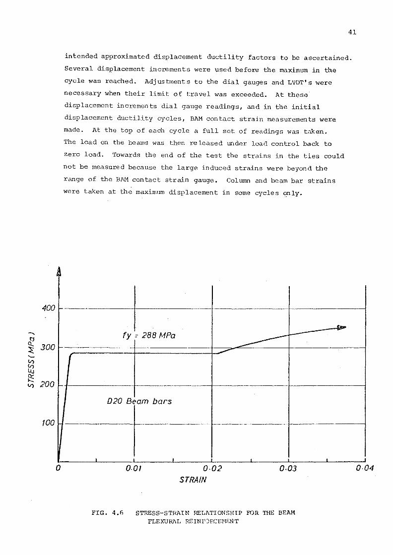
400
-~ 300 -V)
f2 ~ V) 200
100
~~
r-
-
!-
0
41
intended approximated displacement ductility factors to be ascertained.
Several displacement increments were used before the maximum in the
cycle was reached. Adjustments to the dial gauges and LVDT's were
necessary when their limit of travel was exceeded. At these
displacement increments dial gauge readings, and in the initial
displacement ductility cycles, BAM contact strain measurements were
made. At the top of each cycle a full set of readings was taken.
The load on the beams was then released under load control back to
zero load. Towards the end of the test the strains in the ties could
not be measured because the large induced strains were beyond the
range of the BAM contact strain gauge. Column and beam bar strains
were taken at the maximum displacement in some cycles o.nly.
(
fy = 288 MPa
020 Beam bars
..1 _l I
0.01
~
..1
0·02 STRAIN
----------~
.t __l
o.oJ
FIG. 4.6 STRESS-STRAIN RELATIONSHIP FOR THE BEAM FLEXURAL R8INFJRCEI-tF.NT
_b.
_1 I
0·04
CHAPTER FIVE
TEST RESULTS
5 .l GENERAL BEHAVIOUR
5 .1. 1 Unit Bl
The overall behaviour of the test specimen can be seen in
Figs 5.1 and 5.2, which are the load-deflection plots for the two
beams of the specimen. The amount of physical deterioration of the
joint zone can be ascertained by viewing the accompanying photographs
taken at various stages of the test. Cycles 1-11 are the elastic
42
such that the outer layer of beam steel at the end of the cycle
is near yield at the column face. The shaded area represents the path
of cycles 3(4) - 11(10), which were repeatable in the sense that little
stiffness degradation occurred between Thus for the sake of
clarity, all cycles within the elastic limits were not plotted.
The very small shear pinching in t~e elastic cycles is due to
distortions of the panel zone. In the elastic cycles, fine cracks of
approximately 0. 38 mm maximum width were distributed over a
substantial part of the joint panel. The measured anle of inclination
of these cracks is in the region of 55°-60° the horizontal (Fig. 5.3}.
A full length crack running along the diagonal of the joint was noticed
when the beam shear was 40 kN (0.3P ) indicating that the tensile e
splitting strength of the concrete had been exceeded.
In the elastic cycles there was little change along the shear
failure plane, and the diagonal cracks closed up after unloading.
After the first inelastic cycle, the average beam load reached
an intensity 4% greater than the theoretical ultimate load for the beam.
With two cycles at a displacement ductility of 4, the beam load had
dropped to 70% of the theoretical ultimate, accompanied by drastic
degradation in stiffness. The diagonal cracking became more extensive
and dislodged particles, and yielding in the ties prevented closure of
these cracks after unloading. The cracks in the inelastic cycles were
approximately of 1.2 mm maximum width. As the photographs show, the
cover concrete had been lost and the core concrete had deteriorated to
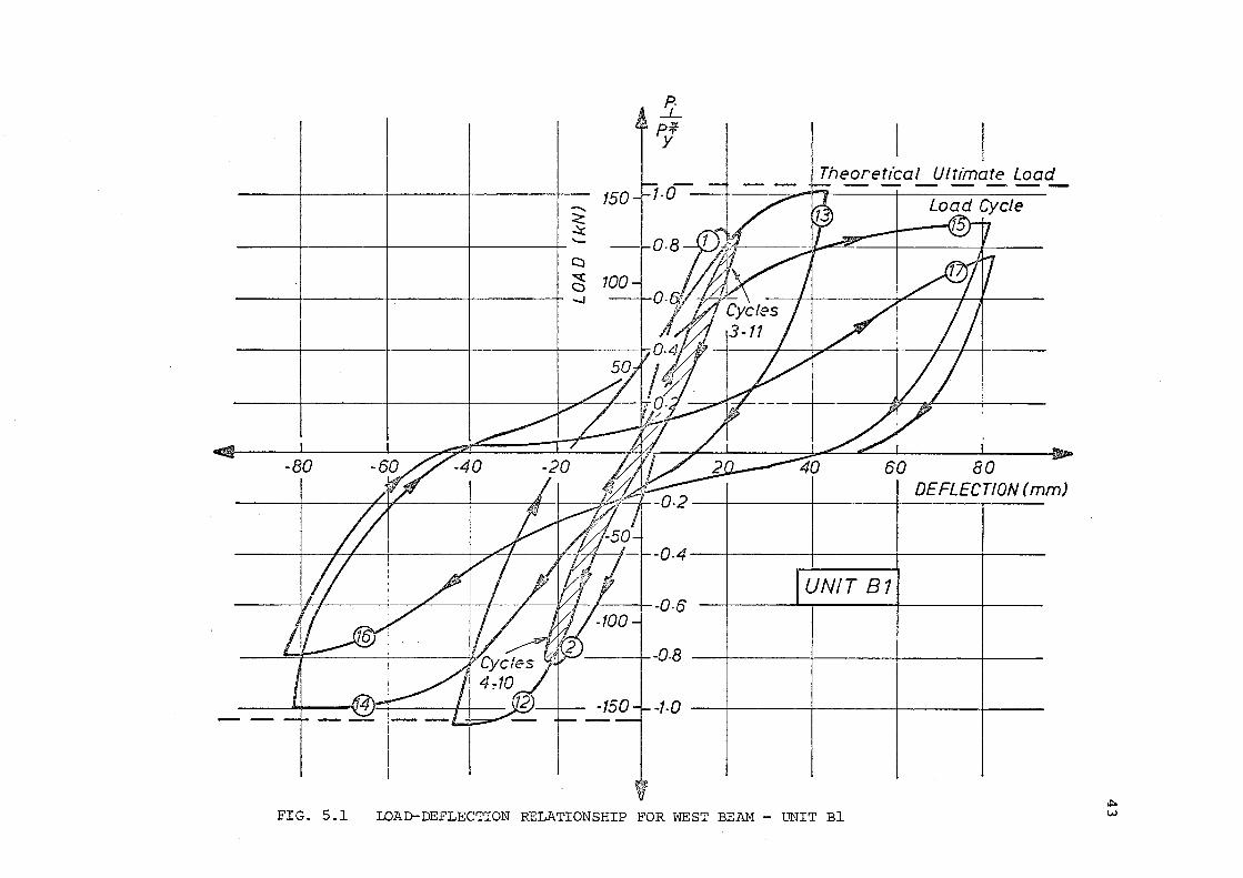
~
~ ~
--------r----------+--------_,-----------r'-~
~ -------+--------~--------+---------+ ~
-80
-0-4
--v--1-----F -0. 6
--;--0-8
-1-0
Theoretical Ultimate Load
80 DEFLECTION (m m)
I UNIT 81 ----
FIG. 5.1 LOAD-DEFLECTION RELATIONSHIP FOR WEST BEAM - UNIT Bl ~ w
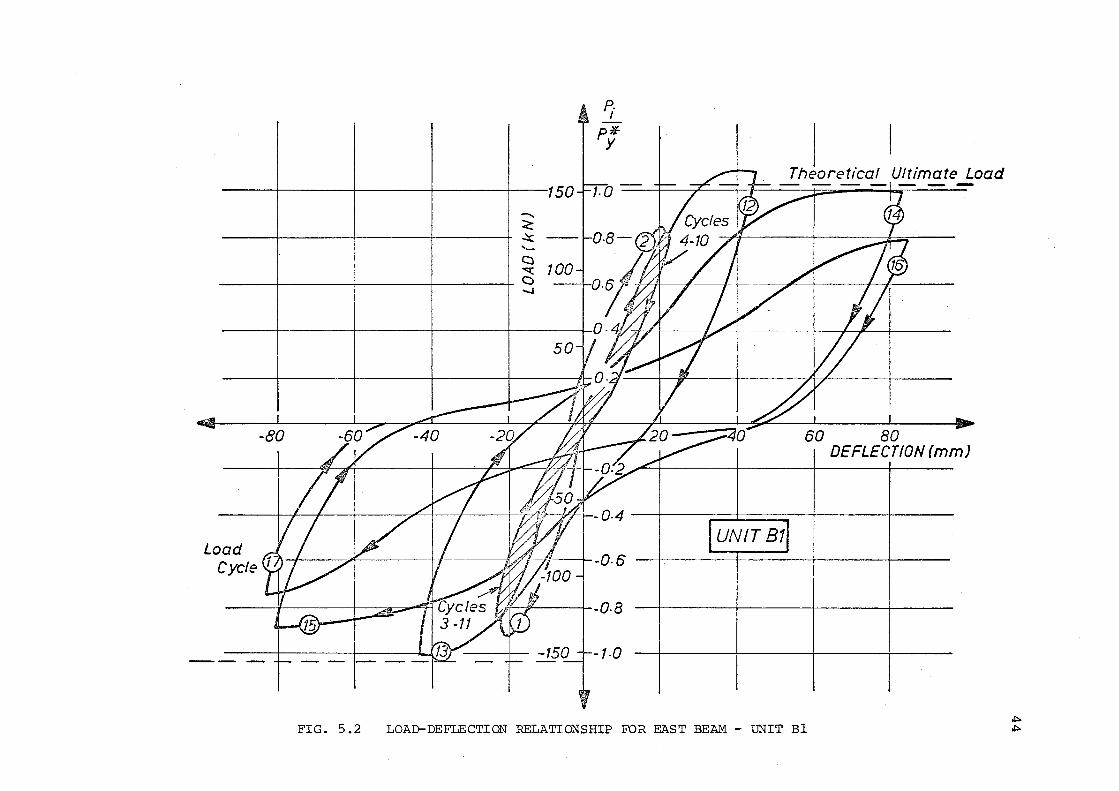
-<: ~ -~ ~
------~--------+-------~---------+ c ~
UNIT 87
I Theoretical Ultimate Load
60 80 DEFLECTION (mm)
Load Cycle (1
I I I I 11/___l__ -0. 6 I
',i-7 ~' I -Q. 8
-1-0
FIG. 5.2 LOAD-DEFLECTION RELATIONSHIP FOR EAST BEAM- UNIT Bl .to .to
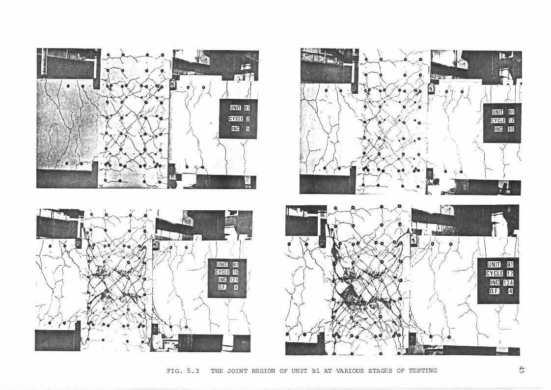
FIG. 5.3 THE JOINT REGION OF UNIT BlAT VARIOUS STAGES OF TESTING """ IJl
the extent that it was completely lacking cohesion and was easily
broken up by hand (see Fig. 5.3).
5 . 1. 2 Unit B2
46
Load-deflection plots for the east and west beams of unit B2 are
given in Figs 5.4 and 5.5. The elastic·cycles 1(2) - 11(12) are
represented by the shaded curve and show little stiffness degradation.
There was little shear distortion in the panel zone when the high axial
column load was present. With the lowering of the axial compression
load from 0.43 P to 0.24 P there was an increase in beam deflection, 0 0
i.e. loss of stiffness, shown in cycles 17 and 18, due to greater
distortions in the panel zone. The photograph shown in Fig. 5.6
indicates that, in the initial elastic cycles, the cracks in the
core developed along the length of the intermediate column bars.
These small cracks, inclined at approximately 70° to the horizontal,
appeared to be initiated by the intermediate bars which weakened the
tension field.
Maximum crack widths in the elastic cycles were approximately
0.33mm. With the subsequent lowering of the axial load and the
application of further elastic load cycles, the cracking in the joint
became more extensive and, although not easily detectable, the crack
inclination appeared to have changed (Fig. 5.6). Due to the high axial
compression load, concrete strut action appeared to be the predominant
mode of shear resistance throughout the test.
In the first inelastic cycle, the load attained was 5% greater
than the theoretical ultimate load for the beam, but upon load reversal
significant load reduction occurred. After three cycles at ductility
of 4, in each direction, the beam load had dropped to 52% of the
theoretical ultimate. The cracking was more extensive, maximum crack
widths of approximately 1.2 mm were measured. After several inelastic
cycles, large diagonal cracks had opened up with yielding of the joint
ties. These cracks covered the full width of the joint core (Fig. 5.6)
and caused spalling of the cover concrete surrounding the column bars,
nearest to the beams. Yielding of the joint ties would have imposed
transverse tensile strains on the core concrete and this severely
weakened the ·corrpression field. As Fig. 5.6 shows, spalling of the
cover concrete occurred, accompanied by a disintegration of the concrete
core. At this stage of the test the column was losing compression load
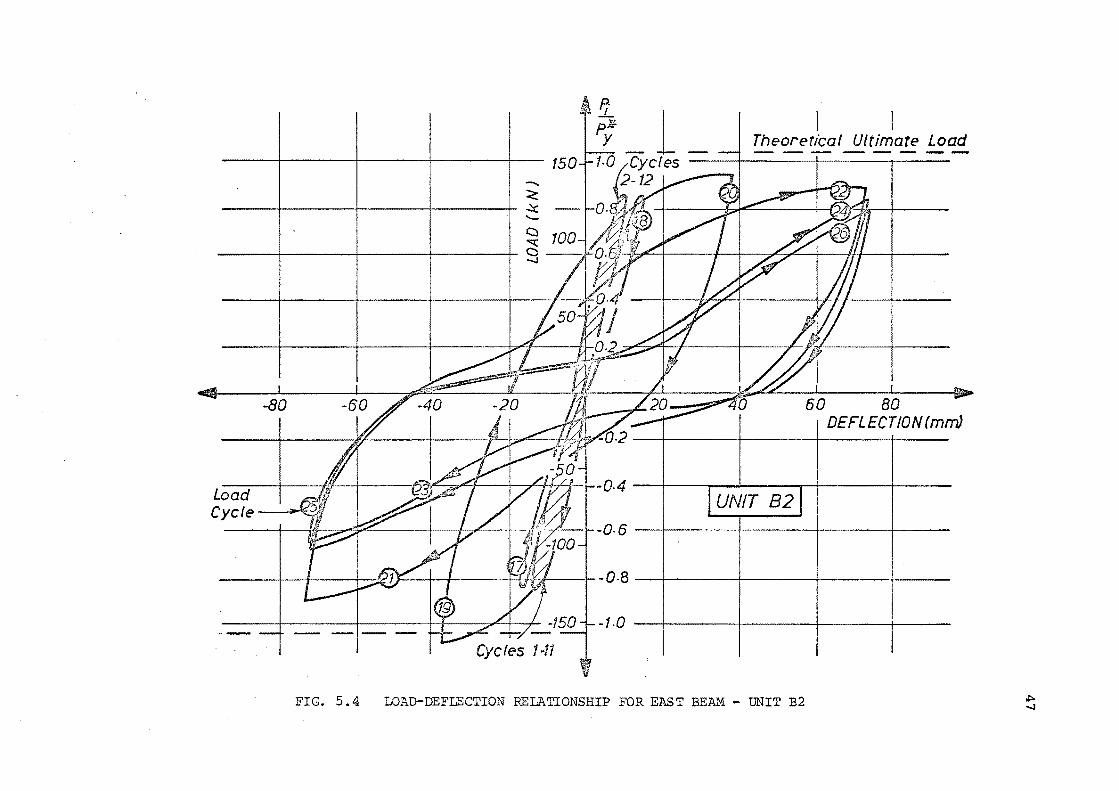
Load Cycfe~
-<: ~ -t::::l
P._1 plf y
I Theoretical Ultimate Load
60 80 DEFLECTION (mm)
UNIT 82
.~--1~-0.8--t------+------4------+-----
-1·0 --+----t-------1---+---
FIG. 5. 4 LOAD-DEFLECTION RELATIONSHIP FOR EAST BEAM - UNIT B2 ~ ...,J
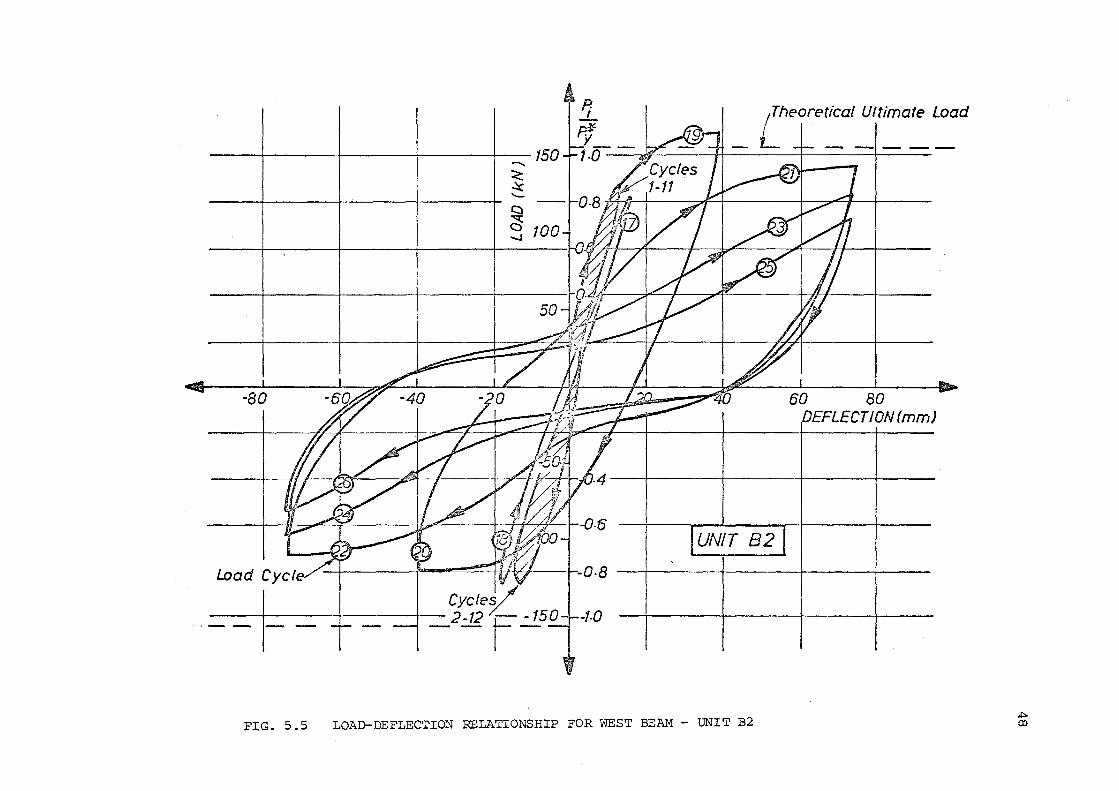
-<: .::c -
Load Cycle J/ CycleL_
. __ I_ _ ± _ ::J _2-t2 ~.:.!..so
/Theoretical Ultimate Load
--- --·----
60 80 DEFLECTION (mm)
UNIT 82
FIG. 5.5 LOAD-DEFLECTION RELATIONSHIP FOR WEST BEAM- UNIT B2 .t> CD
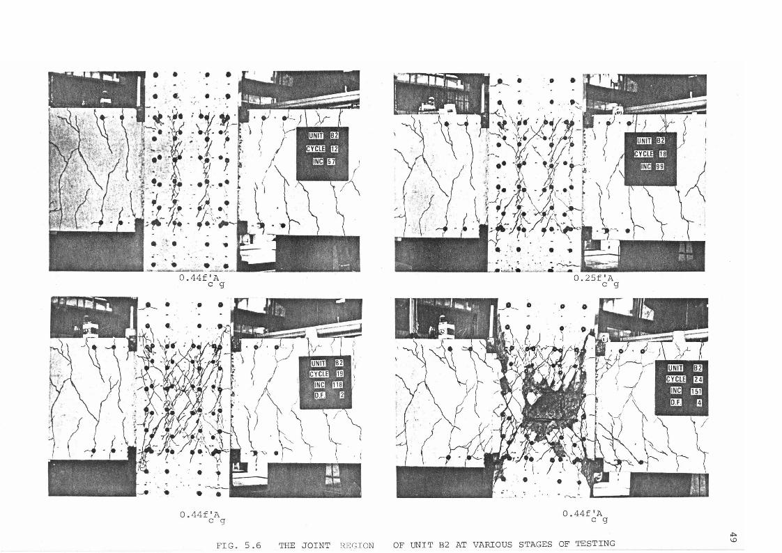
• • •••
.
. :i :~· ·; . ~ ~ .. ,,. ·· \
-11\ ~ ~ ~~!- -~\
'\ . e: .
•
0.'14f'A c g
FIG. 5.6 THE JOINT REGION
0. 25f 'A c g
0 . 44f 'A c g
OF UNIT B2 AT VARIOUS STAGES OF TESTING "" I.D
due to crushing of the concrete in the joint core. The column bars
were required to transfer a much greater compression force across
the joint. Eventual failure appeared to be a compression failure
of the diagonal concrete strut.
5.1.3 Comparison of Units Bland B2
The load-deflection behaviour of the two units showed that
the beam deflection for unit B2 in the elastic load cycles was only
55% of that occurring in unit Bl. This indicates, along with absence
of shear pinching, that the high axial load resulted in a stiffer
joint core.
In the elastic cycles a full corner to corner diagonal crack
appeared in unit Bl, whereas in unit B2 the cracking was concentrated
near the intermediate column bars. This indicated the predominance
of the axial compression in unit B2. With the lowering of the axial
load in unit B2, cracks developed further and extended across the
joint.
The inelas·tic behaviour of the two units was comparable
with respect to crack patterns. The larger cracks that formed
towards the end of the test ended diagonally across the joint in
both units.
From the load-deflection plots it can be seen that in the
inelastic cycles the strength degradation on load reversal was
slightly greater in unit B2 than in unit BL
The two specimens appeared to have different modes of failure.
The diagonal cracks in unit Bl appeared to have been caused mainly
so
by the shear stresses introduced into the joint core. The diagonal
cracks became. wide after yield of the joint stirrups. This was similar
to a diagonal tension failure. In unit B2 the cracking appeared to
be mainly due to the high axial compression causing diagonal splitting.
The yielding of the ties in the inelastic cycles weakened the
compression field. This led to the eventual compression failure of
the core concrete as described in section 5.1.2.
Neither test specimen was able to meet the requirements of
NZS 420316 with respect to ductility. The recommendation of this
code of practice is that primary members of a seismic resisting
system should not lose more than 30% of their stl:ength, after eight
reversals at a displacement ductility factor which corresponds with
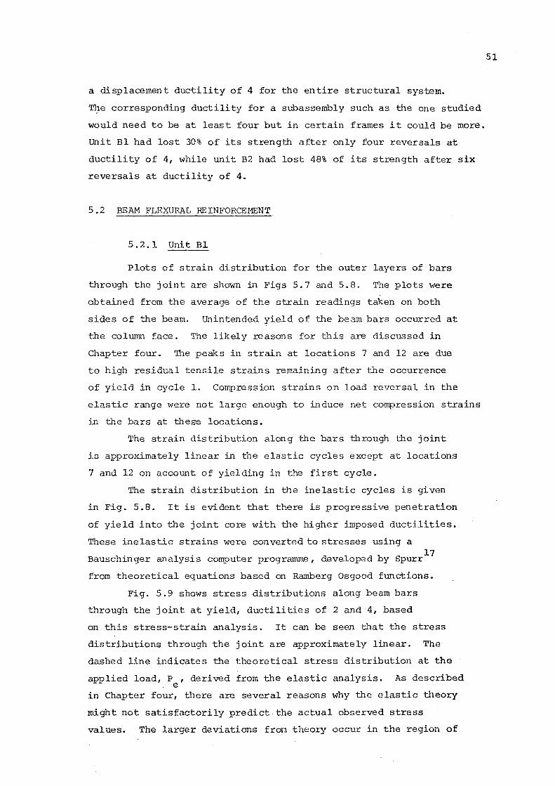
a displacement duc'f:ility of 4 for the en tire structural system.
T~e corresponding ductility for a subassembly such as the one studied
would need to be at least four but in certain frames it could be more.
Unit Bl had lost 30% of its strength after only four reversals at
ductility of 4, while unit B2 had lost 48% of its strength after six
reversals at ductility of 4.
5.2 BEAM FLEXURAL REINFORCEMENT
5. 2. 1 Unit Bl
Plots of strain distribution for the outer layers of bars
through the joint are shown in Figs 5.7 and 5.8. The plots were
obtained from the average of the strain readings taken on both
sides of the beam. Unintended d of the beam bars occurred at
the column face. The likely reasons for this are discussed in
Chapter four. The peaks in strain at locations 7 and 12 are due
to high residual tensile strains remaining after the occurrence
of yield in cycle l. Compression strains on load reversal in the
elastic range were not large enough to induce net compression strains
in the bars at these locations.
The strain distribution along the bars through the joint
is approximately linear in the elastic cycles at locations
7 and 12 on account of yielding in the first cycle.
The strain distribution in the inelastic cycles is given
in Fig. 5.8. It is evident that there is progressive penetration
of yield into the joint core with the higher imposed ductilities.
These inelastic strains were converted to stresses using a 17
Bauschinger analysis computer programme, developed by Spurr
from theoretical equations based on Ramberg Osgood functions.
Fig. 5.9 shows stress distributions along beam bars
through the joint at yield, ductilities of 2 and 4, based
on this stress-strain analysis. It can be seen that the stress
distributions through the joint are approximately linear. The
dashed line indicates the theoretical stress distribution at the
applied load, P , derived from the elastic analysis. As described . e
in Chapter four, ti1ere are several reasons why the elastic theory
might not satisfactorily predict the actual observed stress
values. The larger deviations fran theory occur in the region of
51
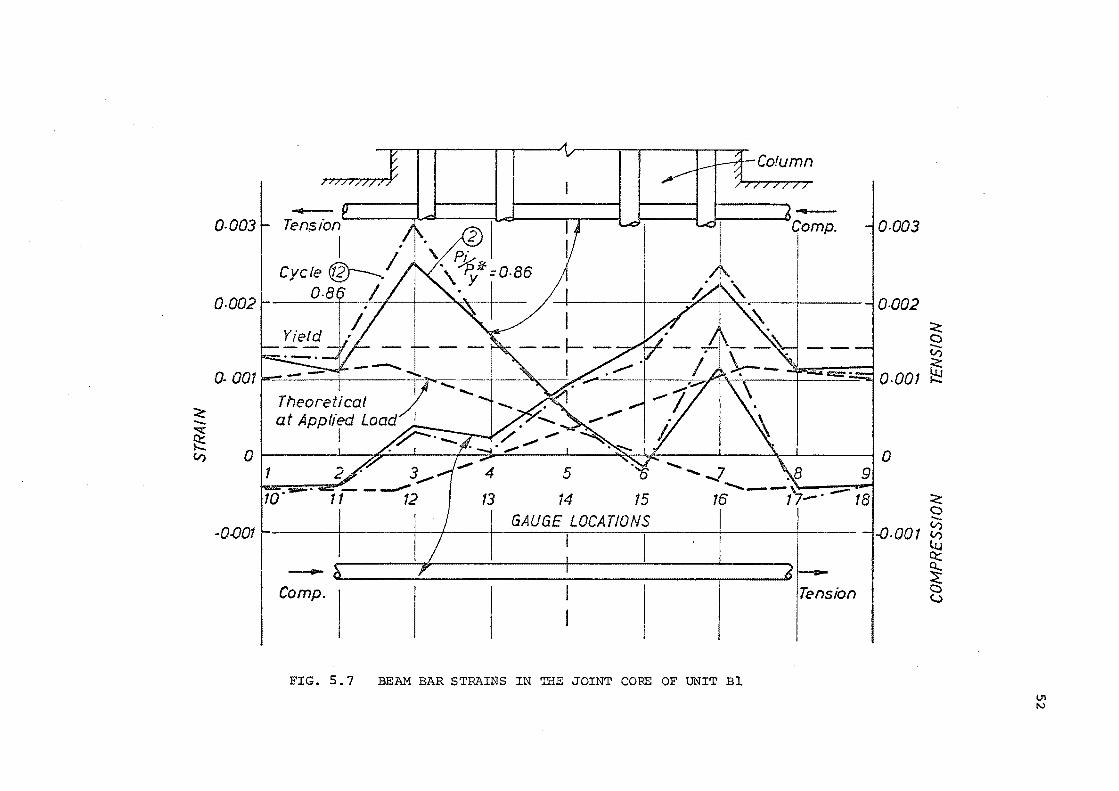
<: -~ ~ V)
0-0031- Tension A.-- ~ I I 1----\.....cll~ l..d 1 Comn. -l 0-003
0-002 / -l0-002 :<: c --~
(). 001~- -l ~ ~~.~j &!~. 1==1o.oo1 ~ Theoretical
-r·"' - ---. ~ ·,.1·~ -\\
0 -z_· ' ( :;;- I
~,,~ ~ gr 1 2 . 3_.1 ..... 4 5 'iO·-· 11- ---;2 13 14 15 16-..... __ t'1-· -1a :<:
GAUGE LOCATIONS c --·0.0011- ! I I ! V)
I I I I I I .Q.QQ 1 V)
Lu 0:::
-~ , I 6 - ~
Comp. 1 I I I I I Tension c (..)
FIG. 5. 7 . BEAM BAR STRAINS IN THE JOINT CORE OF UNIT Bl U1 1'.)
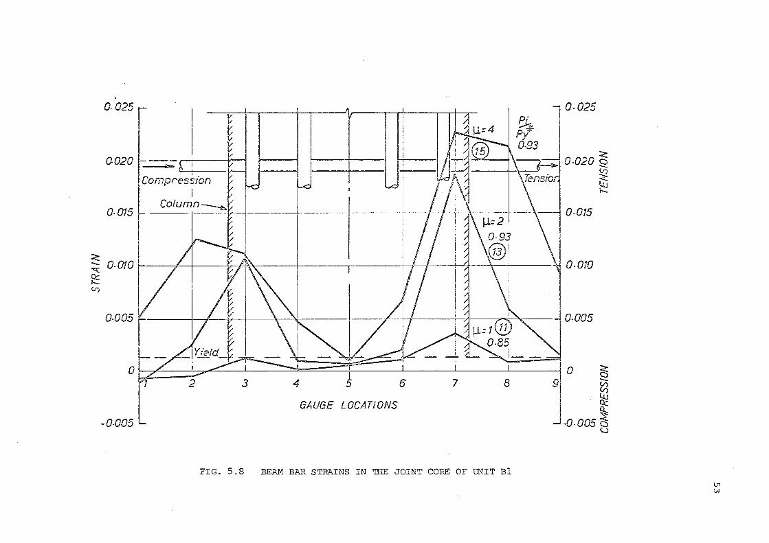
o.o2s[ I ~~~
0.020 I ~ I a.
~i
'!pres::. I
Column --··--~
'F-1
0-025
~t---i-· --+fH~~ 0-010
0-005
I / I ~'=:::::-....I :J ; ... , I 0 ~ I I I --;;;> ::...-- V)
I -0-005-
GAUGE LOCATIONS
FIG. 5.8 BEAM BAR STRAINS IN THE JOINT CORE OF UNIT Bl
9 t3 Q::
~ -0-005 0 <...;
\)1
w
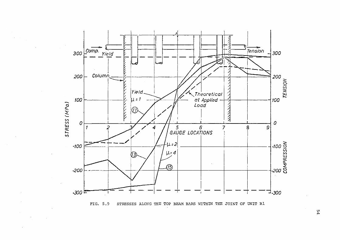
-0 ct. ~ -V) V) llJ Q:: ..... V)
- r rJoa t,2omp. Yi~Id ~ l300
200 I I I // 4 / 1 ~ r ~200 ~ r; ~~ " <:: ~ ' 0 -~ 1001- I t7 Ill= 1
~--+~----~-----,100
0 ~----~----~~~~--~--~----~----~----~----~0
11 2_A / 4 I I 5 6 1 I.../ I GAUGE LOCATIONS
lt--:=-r 1..1- = 21 -100~ I I
-200
-300 b- 1- - - -·- -1--FIG. 5.9 STRESSES ALONG THE TOP BEAM BARS WITHIN THE JOINT OF UNIT Bl
9
<:: -100 2
V)
[ti Q::
~ -200 2
-300
LTI
""'
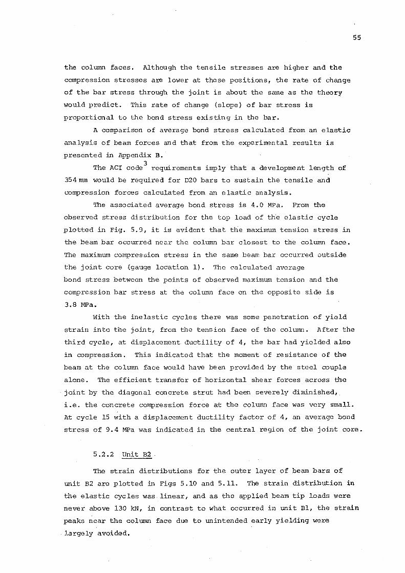
the column faces. Although the tensile stresses are higher and the
compression stresses are lower at these positions, the rate of change
of the bar stress through the joint is about the same as the theory
would predict. This rate of change {slope} of bar stress is
proportional to the bond stress existing in the bar.
A comparison of average bond stress calculated from an elastic
analysis of beam forces and that from the experirrental results is
presented in Appendix B.
The ACI code3
requirements imply that a development length of
354 mm would be required for D20 bars to sustain the tensile and
compression forces calculated from an elastic analysis.
The associated average bond stress is 4.0 MPa. From the
observed stress distribution for the top load of the elastic cycle
plotted in Fig. 5.9, it is evident that the maximum tension stress in
the beam bar occurred near the column bar closest to the column face.
The maximum compression stress in the same beam bar occurred outside
the joint core (gauge location 1). The calculated average
bond stress between the points of observed maximum tension and the
compression bar stress at the column face on the opposite side is
3.8 MPa.
55
With the inelastic cycles there was some penetration of yield
strain into the joint, from the tension face of the column. After the
third cycle, at displacement ductility of 4, the bar had yielded also
in compression. This indicated that the moment of resistance of the
beam at the column face would have been provided by the steel couple
alone. The efficient transfer of horizontal shear forces across the
joint by the diagonal concrete strut had been severely diminished,
i.e. the concrete compression force at the column face was very small.
At cycle 15 with a displacement ductility factor of 4, an average bond
stress of 9.4 MPa was indicated in the central region of the joint core.
5.2.2 Unit B2
The strain distributions for the outer layer of beam bars of
unit B2 are plotted in Figs 5 .10 and 5. 11. 'I.'he strain distribution in
the elastic cycles was linear, and as the applied beam tip loads were
never above 130 kN, in contrast to what occurred in unit Bl, the strain
peaks near the column face due to unintended early yielding were
largely avoided.
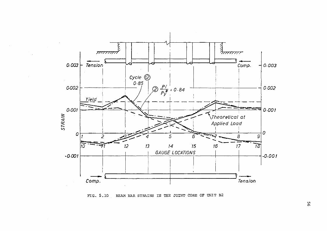
~ --.:::c
~ V)
0.003 ,......._
, __ ----tLd 1 lJCI \....d Comp. Q.QQ3 Tension
o.oo2 o.oo2
Cycle@ '1
o.as 1 .
---+-----r-- I @ ..f.!_ = 0 · 84 , P{.
o.oo1l -- ·--::-r---=----.. .j... "S:(. \ I I ~ ~ ---?4~~-=-:::4 o.oo1
12 13 14 15 16 17
-0-001 GAUGE LOCATIONS -l. -0-001 I
-Comp. Tension
FIG. 5 .lO BEAM BAR STRAINS IN THE JOINT CORE OF UNIT B2
lJ1 C\
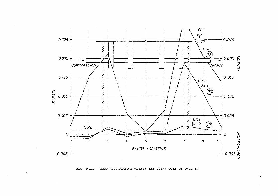
0-025 I_ II \ --~-=±:::==='
0-020 . _---;
~ ~ 0.()10- I I I I
v1 j -~----~~ I • ~ t\ l 0-010 I I T I l
o.oos 1 I I
I
Ol ~ ! ~ .. -'[== ±=: I i I 1 2 3 4 5 6 7 8
i -0-005 L GAUGE LOCATIONS
FIG. S.ll BEAM BAR STRAINS WI?rliN THE JOINT CORE OF UNIT B2
~ V)
<: llJ 1--
l.'l ._J
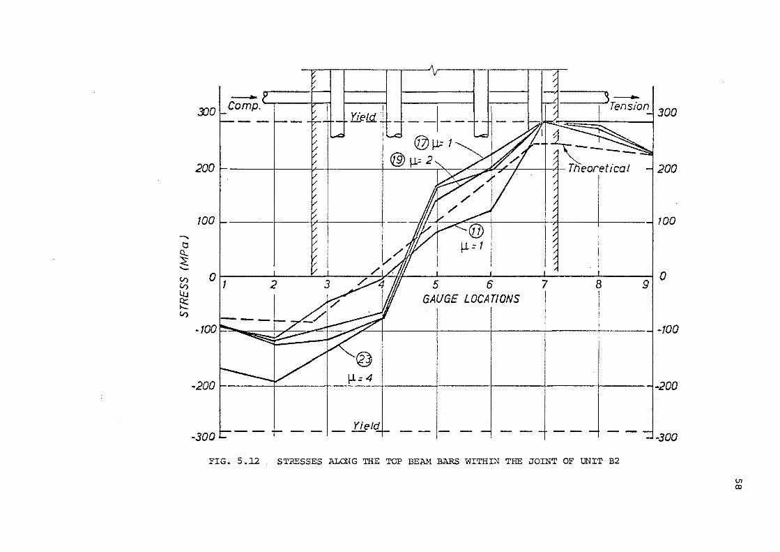
....... 0
~ -V) V) Lu ~ V)
3JO -----,. 3r;;;;Jon • 300
200
© j.1: 1 @)~=2 ~
200
100 t- ---jf;~! Ia I ~ 100
0 II I v t;Pf/ I I I . I
910 2 5 6 7 8 I GAUGE LOCATIONS
-100~ 1/~~ -l-100
-200 1- ~= 4 -200
-300 _ Yield
-300
FIG. 5.12 STRESSES ALONG THE TOP BEAM BARS WITHIN THE JOINT OF UNIT B2
Vl c.o
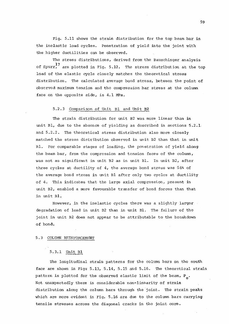
59
Fig. 5.11 shows the strain distribution for the top beam bar in
the inelastic load cycles. Penetration of yield into the joint with
the higher ductilities can be observed.
The stress distributions, derived from the Bauschinger analysis 17
of Spurr, are plotted in Fig. 5.12. The stress distribution at the top
load of the elastic cycle closely matches the theoretical stress
distribution. The calculated average bond stress, between the point of
observed maximum tension and the compression bar stress at the column
face on the opposite side, is 4.1 MPa.
5. 2 • 3 Comparison of Unit Bl and Unit B2
The strain distribution for unit B2 was more linear than in
unit Bl, due to the absence of yielding as described in sections 5.2.1,
and 5.2.2. The theoretical stress distribution also more closely
matched the stress distribution observed in unit B2 than that in unit
Bl. For comparable stages of loading, the penetration of yield along
the beam bar, from the compression and tension faces of the column,
was not as significant in unit B2 as in unit Bl. In unit B2, after
three cycles at ductility of 4, the average bond stress was 54% of
the average bond stress in unit Bl after only two cycles at ductility
of 4. This indicates that the large axial compression, present in
unit B2, enabled a more favourable transfer of bond forces than that
in unit Bl.
However, in the inelastic cycles there was a slightly larger
degradation of load in unit B2 than in unit Bl. 'rhe failure of the
joint in unit B2 does not appear to be attributable to the breakdown
of bond.
5. 3 COLUMN' REINFORCEMENT
5.3.1 Unit Bl
The longitudinal strain patterns for the column bars on the south
face are shown in Figs 5.13, 5.14, 5.15 and 5.16. The theoretical strain
pattern is plotted for the observed elastic limit of the beam, P • e Not unexpectedly there is considerable non-linearity of strain
distribution along the column bars through the joint. The strain peaks
which are more evident in Fig. 5.16 are due to the column bars carrying
tensile stresses across the diagonal cracks in the joint core.
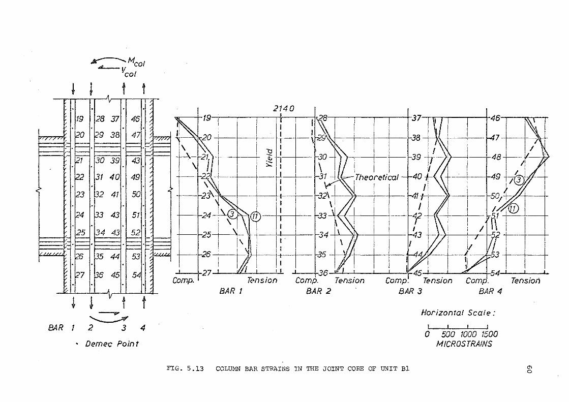
~Mcol 4
vcol
~ J t t
~ ~ v t t ----.. ......____..,
B4R 1 2 3 4
• Demec Point
2140 I w I 19 I I I f I I .l\28'--.---,.----....---..--+-
+--...... 25-+--~1--
+--...... 26 I I 1J I I
I j27 I u. I 'I
Comp. Tension BAR 1
II" I I I I t45 I I 4 I Comp. Tension
BAR 3
Horizontal Scale:
I I I I
0 500 1000 1500 MICROS TRAINS
FIG. 5.13 COLUMN BAR STRAINS IN THE JOINT CORE OF UNIT Bl
I I I
Tension
0'1 0

c.:: -S2 II)
c.:: ~
t
·*t II)
t ~ c c.,
t 2140
L ""~:- . ! ~~- ! ":: LUJ. I t: I Ill 1_'\ I ~ I .... ~ I "r-21 + 30 ............ ~39 I ....... ' I l AB '
\ ~, ~-- I v It I i /1 22 I \ I -~ I 31 ,..~ I 40 / I I 49 I / ~ i
1- · " I ::.... I -r--. , I r-· --._ -I I r-• l I \ i I
. '-..1 I !pe' ~---~ I I !I ~23 I 'k I -32 I --- "!::- -41 I I J..t.-'"- r-50 ~I ;. :
: I II I ~~ ~!I : I 11
r-24 : ! I -33 _....- I I -42 ~ I 51 . I : I I ' ' I i"'-.. I "\I I '/ I I I
I I i "" I I ,. 1-25 i I ~4 ~ i- -43 ""' I ~ I i I
I \ I 1/ I L I I \1 I I I I /"T/ r6
1 1 1
• 35 / ---~~ ~44 I -53 ~ • a 1 I /I' V I' ~ : ;:;::--- I• ~ ~ 27 I i y d I -36 L I ~ I I ~ 54 I I ' I I t Comp.l Tension Comp.l Tension Comp. '..J Tension Comp. Tension
BAR 1 BAR 2 BAR 3 BAR 4
Cycle No.12 at ~= 2 Horizontal Scale:
0 500 1000 1500 MICROSTRAINS
FIG. 5.14 COLUMN BAR STRAINS IN THE JOINT CORE OF UNIT Bl en 1-'
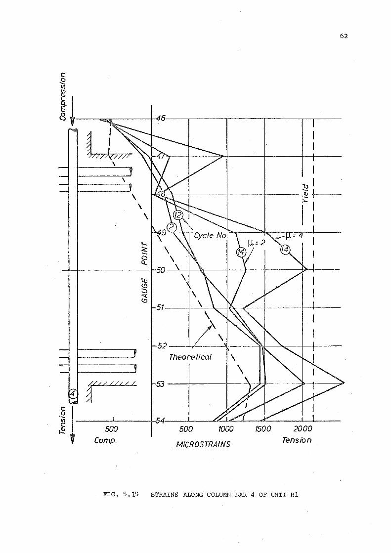
c: 0 ·-(1)
62
~I 8 y----~-------+4o---~----~------.------.-.-----
\
\
-----
/./// //// /
a
I l:JI
-+--1------t--·---t----- .~ +-1-)...1
I I
Theoretical
1500 2000 Tension
FIG. 5.15 STRAINS ALONG COLUMN BAR 4 OF UNIT Bl
c: .~ V) V)
~ ~ 8
500 Comp.
500 1000
MICROSTRA/NS
1500 2000 Tension
FIG. 5 •. 16 STRAINS ALONG COLUMN BAR 3 OF UNIT Bl
63
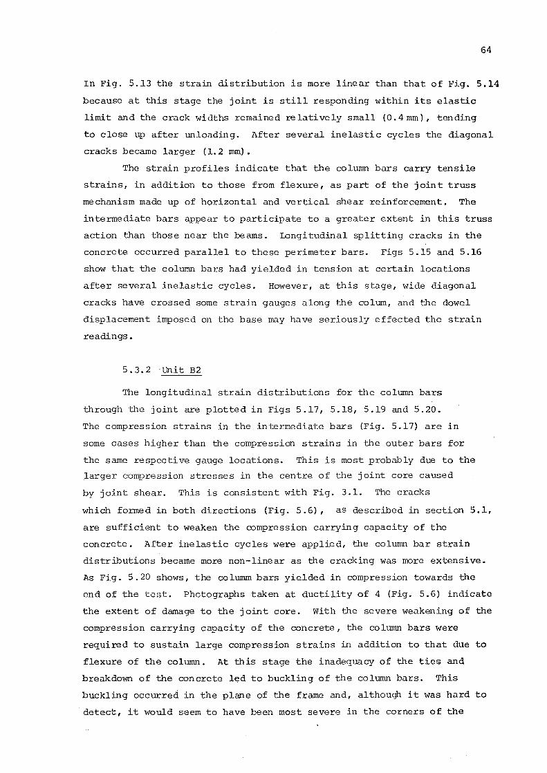
64
In Fig. 5.13 the strain distribution is more linear than that of Fig. 5.14
because at this stage the joint is still responding within its elastic
limit and the crack widths remained relatively small (0. 4 mm), tending
to close up after unloading. After several inelastic cycles the diagonal
cracks became larger (1.2 rom).
The strain profiles indicate that the column bars carry tensile
strains, in addition to those from flexure, as part of the joint truss
mechanism made up of horizontal and vertical shear reinforcement. The
intermediate bars appear to participate to a greater extent in this truss
action than those near the beams. Longitudinal splitting cracks in the
concrete occurred parallel to these perimeter bars. Figs 5.15 and 5.16
show that the column bars had yielded in tension at certain locations
after several inelastic cycles. However, at this stage, wide diagonal
cracks have crossed some strain gauges along the colum, and the dowel
displacement imposed on the base may have seriously effected the strain
readings.
5.3.2 Unit B2
The longitudinal strain distributions for the column bars
through the joint are plotted in Figs 5.17, 5.18, 5.19 and 5.20.
The compression strains in the intermediate bars (Fig. 5.17) are in
some cases higher than the compression strains in the outer bars for
the same respective gauge locations. This is most probably due to the
larger compression stresses in the centre of the joint core caused
by joint shear. This is consistent with Fig. 3.1. The cracks
which formed in both directions (Fig. 5.6), as described in section 5.1,
are sufficient to weaken the compression carrying capacity of the
concrete. After inelastic cycles were applied, the column bar strain
distributions became more non-linear as the cracking was more extensive.
As Fig. 5.20 shows, the columm bars yielded in compression towards the
end of the test .. Photographs taken at ductility of 4 (Fig. 5.6) indicate
the extent of damage to the joint core. With the severe weakening of the
compression carrying capacity of the concrete, the column bars were
required to sustain large compression strains in addition to that due to
flexure of the column. At this stage the inadequacy of the ties and
breakdown of the concrete led to buckling of t:he column bars. This
buckling occurred in the plane of the frame and, although it was hard to
detect, it would seem to have been most severe in the corners of the
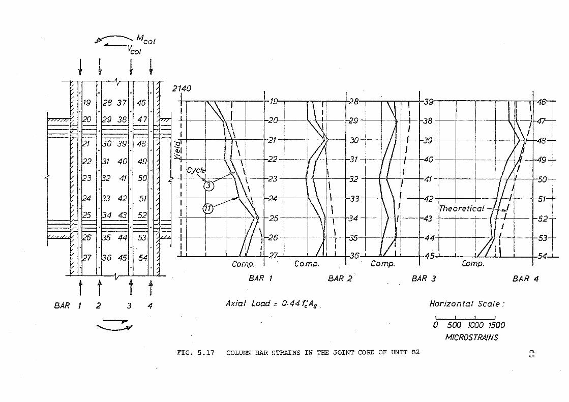
~Mcol Vcot
~ ~
BAR 1 2
31 40
~ 41
~ +
t t 3 4
,.... ............___
-t-r---...r-r~.--..-..,...--i-10 ' • ' . ' I i28 ' ":10 I I I I I .. I I '
-+---i--'i-~1-30 I I I I I I
·1 i I ----tl-- 22 I
I I ',,J ,...q \ \ a I 23 I (!
BAR 1
Axial Load = 0-44 t;A9
·+---+-31 -+---YI-+-+--+-40 -+--+--+--
BAR 2
-+--ll+-1 -t • 41 I .' I il I
t-----+--42 -+---+--t--
Theoretical 43 --+-
I P' I I ' 45 I I l£ , I ' I I ~
Comp. Comp.
BAR 3
Horizontal Scale:
0 500 1000 1500
MICROS TRAINS
BAR 4
FIG. 5.17 COLUMN BAR STRAINS IN THE JOINT CORE OF UNIT B2 0\ V1
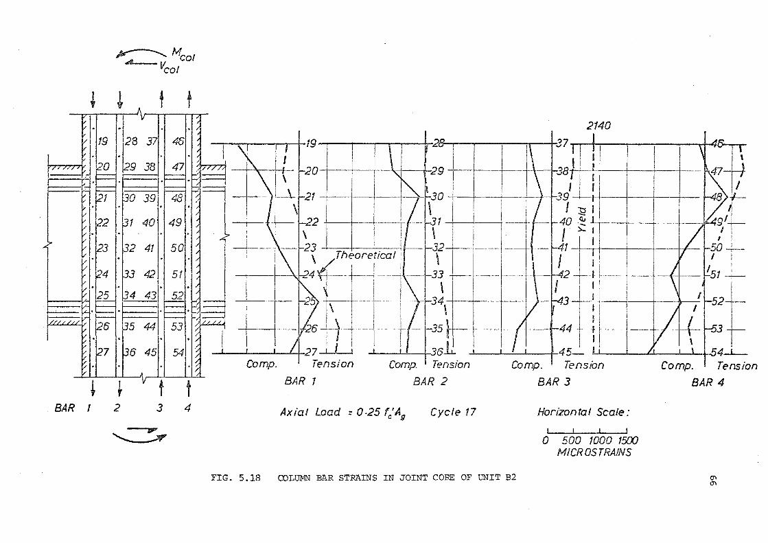
y---....... Mcot A Vcot
! !. t t
28 37
~ ~ t t BAR 1 2 3 4
~
2140
. 19 . 28 I I I II I 1 1 I, 1 cl 4~
Tension
BAR 1
Comp. 1 Tension
BAR 2
Axial Load :: 0-25 fc'A9
Cycle 17
I I t I
Comp. 1 Tension
BAR 3
Horizontal Scale:
500 1000 1500 MICROS TRAINS
FIG. 5.18 COLUMN BAR STRAINS IN JOINT CORE OF UNIT B2
.47-+f B>Y-
+-lL49'+I I
I !
.so-t-' l I .
--(--f-- !-51 --;--
Comp. I Tension
BAR 4
0'1 0'1
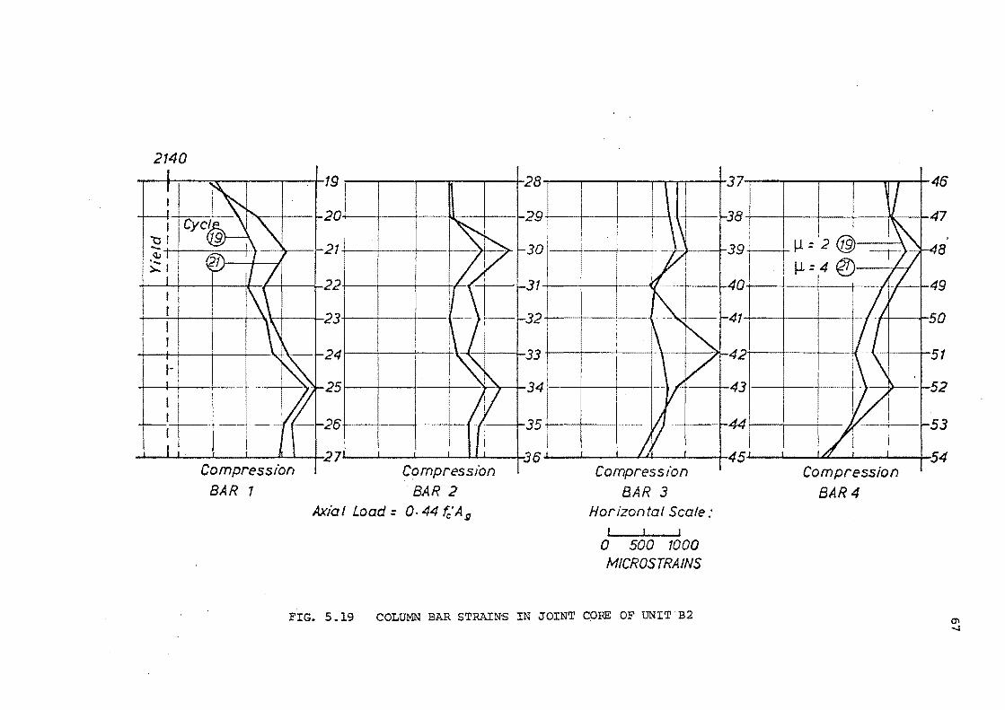
2140
• 19 ' 28 ' 37 46
Compression
BAR 1
+----+- 11 = 2 @)·---->. 8 l-L=4@ //
32. I--{ 41-i-. --+---!-......_., II .,'-50
24 l~ ---i-33 +----+--+----! I ~42r'-~--r-- +----+-51
25 ~'\---+
26 +
Compression
BAR 2
Axial Load= Q. 44 fc'Ag
A 431--+--+----+
441----+---1-
.L--.L.--L..-...LJ..J---L---+-45 r I 'a , I I 54 Compress t"on
BAR 3 Horizontal Scale:
I I l
0 500 1000 MICROSTRAJNS
Compression
BAR4
FIG. 5 .19 COLUMN BAR STRAINS IN JOINT C()RE OF UNIT B2 11\ -..1
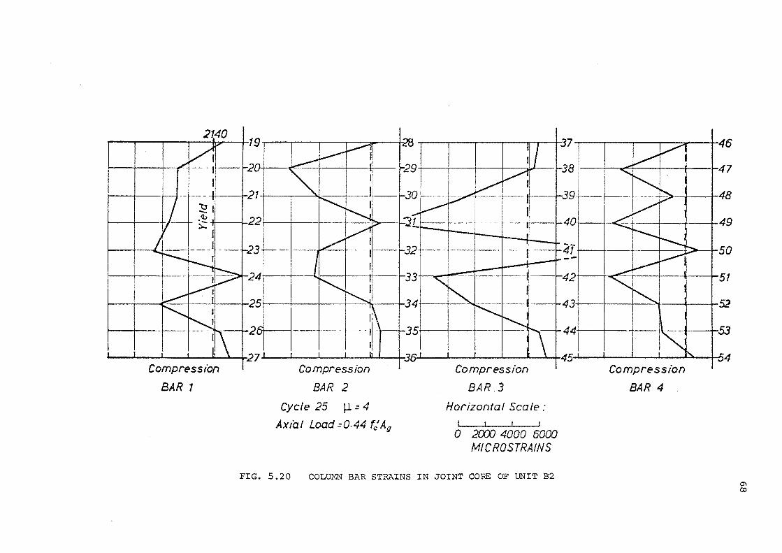
2140
Compression
BAR 1
Compression
BAR 2
Cycle 25 :4
Ax/a! Load =0-44 t"r/A9
Compression
BAR 3
Horizontal Scale:
0 20Cf) 4000 6000 MICROSTRAINS
FIG. 5.20 COLUMN BAR STRAINS IN JOINT CORE OF UNIT B2
46
47
48
L~~J 4 -+- ..... . 49
50
51
::llli l 1: 4
Compression
BAR 4
c:r. co
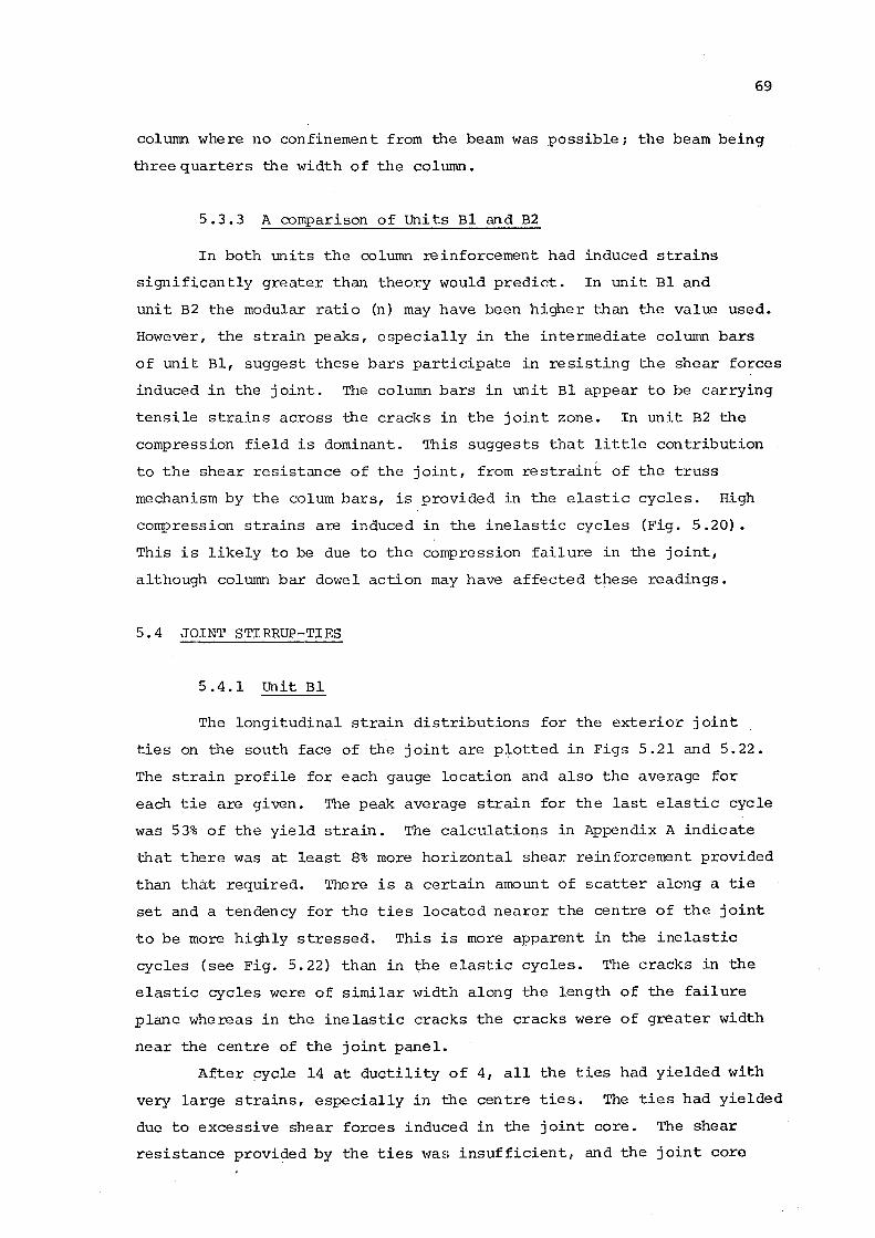
69
column where no confinement from the beam was possible; the beam being
three quarters the width of the column.
5. 3. 3 A comparison of Units Bl and B2
In both units the column reinforcement had induced strains
significantly greater than theory would predict. In unit Bl and
unit B2 the modular ratio (n) may have been higher than the value used.
However, the strain peaks, especially in the intermediate column bars
of unit Bl, suggest these bars participate in resisting the shear forces
induced in the joint. The column bars in unit Bl appear to be carrying
tensile strains across the cracks in the joint zone. In unit B2 the
compression field is dominant. This suggests that little contribution
to the shear resistance of the joint, from restraint of the truss
mechanism by the colum bars, is provided in the elastic cycles. High
compression strains are induced in the inelastic cycles (Fig. 5.20).
This is likely to be due to the compression failure in the joint,
although column bar dowel action may have affected these readings.
5.4 JOINT STIRRUP-TIES
5.4.1 Unit Bl
The longitudinal strain distributions for the exterior joint
ties on the south face of the joint are plotted in Figs 5.21 and 5.22.
The strain profile for each gauge location and also the average for
each tie are given. The peak average strain for the last elas·tic cycle
was 53% of the yield strain. The calculations in Appendix A indicate
that there was at least 8% more horizontal shear reinforcement provided
than that required. There is a certain amount of scatter along a tie
set and a tendency for the ties located nearer the centre of the joint
to be more highly stressed. This is more apparent in the inelastic
cycles (see Fig. 5.22) than in the elastic cycles. The cracks in the
elastic cycles were of similar width along the length of the failure
plane whereas in the inelastic cracks the cracks were of greater width
near the centre of the joint panel.
After ~ycle 14 at ductility of 4, all the ties had yielded with
very large strains, especially in the centre ties. The ties had yielded
due to excessive shear forces induced in the joint core. The shear
resistance provided by the ties \'TaE: insufficient, and the joint core

100 -
0
-~ E '- 500 ..... lJ: 1.( C> V) 400 ~ ~ CQ
lU 300 ::::,.. C> co ""'(
...... 200 ::t: (!:) -~ too~~-
0
400
400
70
BEAM TOP
Pi * =0.91 1 -~------+FY-----4-~----~=:J L
Cycle 1 A B C • • • • e e • o
verage --~~----+---~
-----+-t------+--l. Steiger Point ~ 800 1200 1600 2000 MICROS TRAINS
BEAM TOP
Cycle 12
1:31 -.~I --- _)..:t __ _
I I
1 - --Average _____ ---r----'
---+-- J---+----1
800 1200 1600 2000
MICROSTRAINS
FIG. 5.21 JOINT TIE TENSION STRAIN DISTRIBUTION IN UNIT Bl ELASTIC LOAD CYCLES
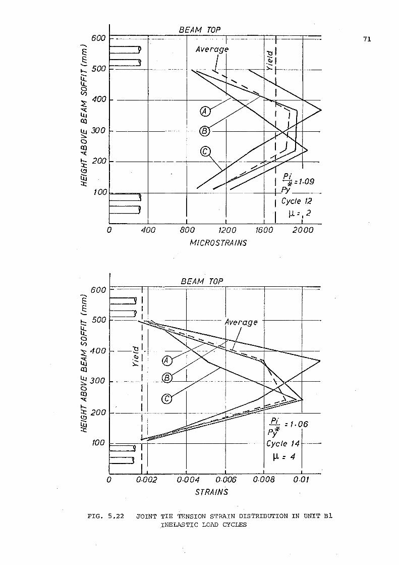
BEAM TOP
---1----------------t-
Pi I *=t.o9 -+-------~~fY ____ _
1 Cycle 12
., ll =I 2
0 400 800 1200 1600 2000
MICROS TRAINS
BEAM TOP 600 .....,
I E: E: I - I .._ 500 - I lt C> I V)
"'01 ~ 400 - ......
~ ·~I co )...I
~ 300 I C> I Q)
"" .._ :X: 200 (!J -~ ::t:
100
0 o.oo2 Q.004 Q.006 o.ooa o.ot STRAINS
FIG. 5.22 JOINT TIE TENSION STRAIN DISTRIBUTION IN UNIT Bl INELASTIC LOlill CYCLES
71

72
disintegrated after several inelastic cycles due to the breakdown of the
concrete and steel shear resisting mechanisms.
5. 4.2 Unit B2
The strain distributions for the joint ties are plotted in
Figs 5.23 and 5.24. The maximum average strain at the high axial load,
2890 kN (0.44 f' A ) , was 52% of yield strain. The calculations in c g
Appendix A indicated that the area of horizontal joint shear reinforcement
provided for ooit B2 was 13.5% less than that required. There was little
increase in strain throughout the elastic cycles. With the lowering of
the axial load to 2204 kN (0. 34 f 'A ) the tie strains increased only c g
slightly. When the axial load was lowered to 1645 kN ( 0. 25 f ' A ) there c g
was a larger scatter of strain readings between locations in a tie set
and between the tie sets; the centre ties being more highly stressed.
At this stage a maximum average strain of 70% of yield strain was
measured. After the first inelastic cycle all the joint ties had yielded.
Very large strains were recorded in the ties towards tile end of the test
and it was apparent that little shear resistance would have been
provided by these ties at this stage. However,, a substantial
contribution to shear resistance would have instead been provided by
dowel action of the column reinforcement.
5.4.3 A Comparison of Units Bl and B2
Both specimens performed satisfactorily in the elastic cycles
with low strains being recorded in the outer ties. It is apparent that
a small amount of degradation in the concrete shear resisting mechanism
occurred. Moreover the strains measured in the ties did not increase by
more than 16% during this initial part of the best. During the inelastic
loading, all the ties in unit B2 yielded in the first cycles, whereas in
unit Bl yielding of all the ties occurred only after the third cycle of
inelastic loading. As Table 4.3 shows, the horizontal joint shear
reinforcement in ooit Bl was 3.82 times that provided in unit B2 •.
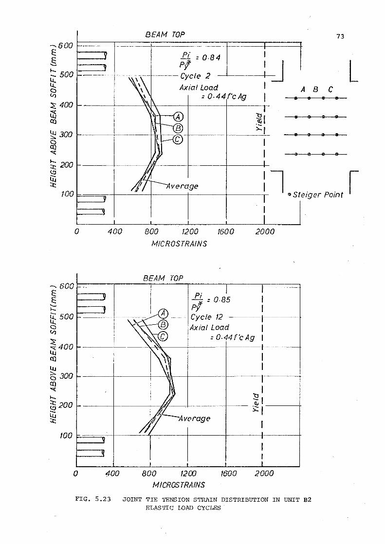
BEAM TOP ....... 6 00 ---+---- --- ---------- ----- --------E t----
§. ':: 500 tt <::> V)
~ 400 ll5 co ~ 300 <::> co ""(
~ 200
Pt' = 0·84 I Pf I
---Cycle 2 I Axial Load I
= 0. 4 4 f'c Ag 1 ---r ~I ~I
73
J L A B C
• 0 Ill •
• 0 8 •
~ 100 F==:=n---r-----t-----r----r-----.-l•Steiger Point ~ 0 400 800 1200 1600 2000
MICROSTRAINS
-600~==~====~=====+=====+===--==t=~=--~~~
~ I ~ I [ 500 t-----t c I V) I ~400 ltj co l.tJ =a 300 C() ""(
'-~200 .._
~
0 400
I ~I __ ,_ ___ ~~---~
~verage I
800 1200 1600 2000 MICROS TRAINS
FIG. 5.23 JOINT TIE TENSION STRAIN DISTRIBUTION IN UNIT B2 ELASTIC LOAD CYCI.ES
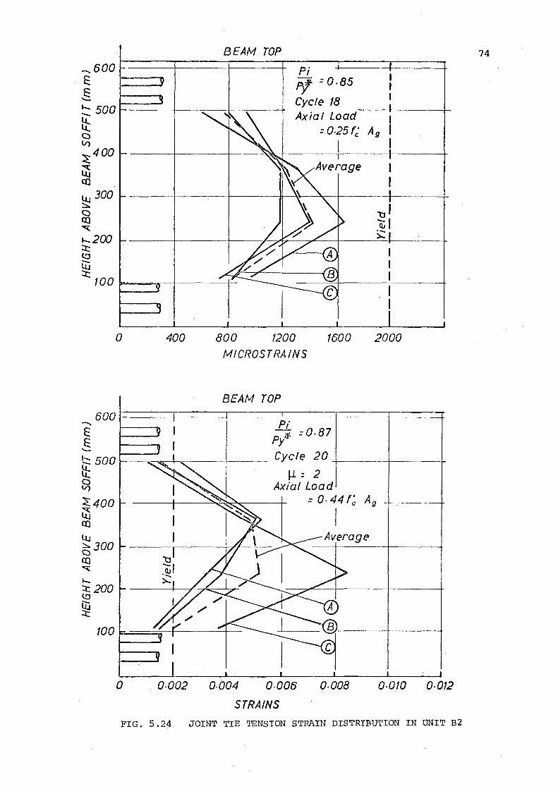
--..600 E 1--......
§ ...... 500 -tt C) V)
~400
~ co ltJ 300 ::::..: C) co '"G::
1-200 :X:: (!J
lij
:X:: 100 P.......~~-+
600 -E E '--
~ 500 LC ~ ~400 l5 co ltJ f3300 (() "<:(
...... ::t::200 (!J
ijJ :X:
0 400
BEAM TOP
Pi Pf = 0.85
Cycle 18 Axial Load
= 025fc' Ag
800 1200 1600 fvf I CROS TRAINS
BEAM TOP
Pi Pyf'f = o. 87
Cycle 20 -+--
~ = 2 Axial Load
2000
= o. 44 f~ A9
I
0 o.oo2 o.oo4 o.oo6 o.ooa o.oto o.012 STRAINS
FIG. 5. 24 JOINT TIE TENSION STRAIN DISTRIBU'l'ION IN UNIT B2
74
CHAPTER SIX
THE INFLUENCE OF SOME VARIABLES ON ELASTIC JOINT BEHAVIOUR
6.1 INTRODUCTION
A number of variables that could influence the behaviour of
an elastic beam-column joint are considered in this chapter.
Three variables were chosen for case studies as they affect elastic
joints. The results of these analyses are presented, and conclusions
are drawn from them.
Factors Affecting Joint Behaviour
(a) Magnitude of axial load
(b) Horizontal joint shear reinforcement
(c) Confinement reinforcement in the joint
(d) Intersecting beams at the joint
(e) Vertical joint shear reinforcement
(f) Relative and absolute quantities of beam top and
bottom flexual reinforcement content
(g) Joint aspect ratio
(h) Amount and distribution of column reinforcement
(i) Aggregate interlock
(j) Dowel action
(k) Bond transfer and yield penetration
(1) Diameter of beam and column bars
(m) Special joint steel devices
6.2 MAGNITUDE OF AXIAL LOAD
Axial compression can be expected to improve joint behaviour
and reduce the demand for joint shear reinforcement. The mechanism
of the diagonal concrete strut described in Chapter three indicates
how axial compression can enhance joint behaviour. As suggested, a
steeper diagonal concrete strut forms as a result of an enlarged
compression block across the column section, and consequent reduction
of the internal lever arm (Fig. 3.1). To maintain the inclination of
75
the strut the share of the horizontal steel force,6Tc, that will combine
with the total column compression stresses, must become larger (Fig. 3 .8).
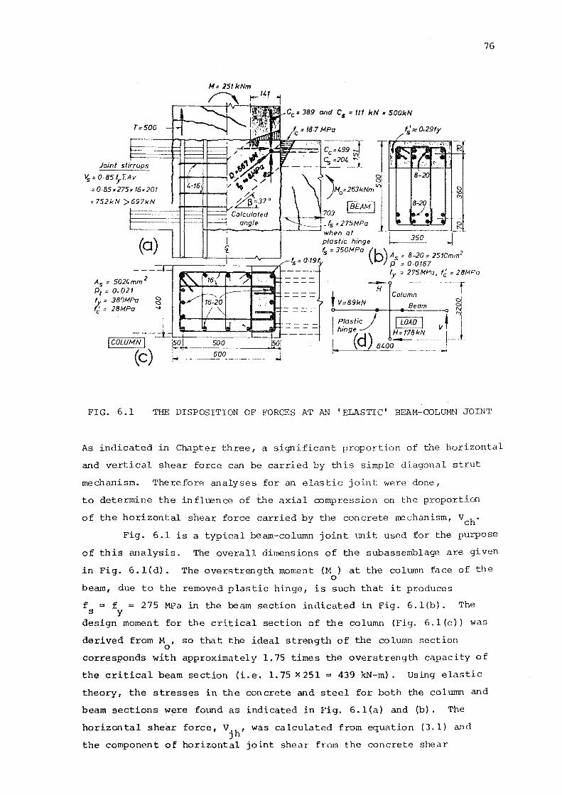
Joint stirrups
~:.085).-[Av
:: o.as x275x 16x201
=752kN>~6~9~7k~N~~~B==1~~
As= 502t.mm 2
p1 = o.a21 fy = JBOMPa fc:: 2BMPa
jCOLU/'vfN I (c)
Cc = 389 and C5 = 111 I<N " 500/<N
when at plastic hinge
fs = 350MPa (b) 2 l _ 0 19
, As 8-20" 2510mm s- · y p ::0.0167
fy = 275/.IPa, f~ =28/.IPa
-;;- --·r t Column
V:89kN Beam ~
I Plastic_} I LOAD I ~ l ' hmge H=178kN VI j ld (d) _6400-:- _j .
76
FIG. 6.1 THE DISPOSITION OF FORCES AT AN 'ELASTIC' BEAM-COLUMN JOINT
As indicated in Chapter three, a significant proportion of the horizontal
and vertical shear force can be carried by this simple diagonal strut
mechanism. Therefore analyses for an elastic joint were done,
to determine the influence of the axial compression on the proportion I
of the horizontal shear force carried by the concrete trechanism, V ch •
Fig. 6.1 is a typical beam-column joint unit used for the purpose
of this analysis. The overall dimensions of the subassemblage are given
in Fig. 6.1 (d). The overstrength moment (M ) .at the column face of the 0
beam, due to the removed plastic hinge, is such that it produces
f = f = s y 275 MPa in the beam section indicated in Fig. 6.l(b). The
design moment for the critical section of the column (Fig. 6.l(c)) was
derived from M , so that the ideal strength of the column section 0
corresponds with approximately 1.75 times the overstrength capacity of
the critical beam section (i.e. l.75X251 = 439 kN-m). Using elastic
theory, the stresses in the concrete and steel for both the column and
beam sections were found as indicated in Fig. 6.l(a) and (b). The
horizontal shear force, V.h' was calculated from equation (3.1) and . J
the component of horizontal joint shear from the concrete shear
resisting mechanism, Vch' from equation (3.2). ~T , as described c
in Chapter three, is the assumed bond force transferred from the
beam steel to the surrounding concrete within the depth of the
diagonal concrete strut, and it was calculated as
77
6T = y (A I f I + A f ) c s s s y
(6.1)
An upper and lower bound for Y was chosen so that
2/3 < _y__ < 1.0 - kcol
Fig. 6.l(a) indicates the magnitude of the diagonal concrete
strut, i.e. D in Fig. 3.2, for the case of zero axial compression. c
The average diagonal compression·on the strut is shown to be
8 MPa ~ f '/4. The calculated inclination of the diagonal concrete c
strut, S, is shown in Fig. 6.l(a). The position of equilibrium of
the internal horizontal and vertical forces contributing to the
concrete shear resisting mechanism, D , is shown in Fig. 6.l(a) c
for the forces at the top right-hand corner of ·the free body.
For simplicity, the intermediate column bars were not considered in
the calculation of the column steel force at the critical section
(i.e. C "' in Fig. 3. 4) . Diagonally opposi·te a similar position s can be found from equilibrium of the internal horizontal and vertical
forces contributing to D , at the bottom left-hand corner of the joint. c
For the case of equal top and bottom beam reinforcement the two points
of equilibrium are in a similar location with respect to the boundaries
of the joint. The diagonal compression strut must intersect these
points of equilibrit~ as shown in Fig. 6.l(a). From the dimensions of
the joint the inclination of the strut can be approximated. An
alternative approach is to obtain S simply by considering all the
internal horizontal and vertical forces as acting at the boundary of
the joint core (Fig. 3.3). This assumed value of Sis usually quite
close to the value of S calculated from joint geometry when the centroids
of the internal concrete and steel forces are located near the boundary
of the joint core, as shown in Fig. 6.l(a). With axial compression on
the column section the centroid of the concrete compression force in
the column shifts towards the centre of the column. An 'exact'
calculation of the line of thrust of the diagonal concrete strut would
need to consider the position of this column concrete compression force
as well as the forces in, and the positions of the intermediate column
bars. However, the simplifications involved in postulat~ng these
mechanisms do not warrant a high degree of accuracy.
The horizontal joint shear force asstlll'ed to be carried by the
truss mechanism, Vsh' was obtained from equation (3.3). The area of
horizontal shear reinforcement, A , was calculated using an under-v
capacity factor (¢) of 0.85, as shown in Fig. 6.l(a).
The vertical component of the joint shear force, V. , was JV
estimated from Vjh and S. This enabled calculation of the vertical
78
shear force to be transferred by the truss mechanism, V (equation 3.5). SV
This vertical shear force was assumed to be provided by intermediate
vertical column bars only. The area of the intermediate bars required
was calculated in a similar manner to that for the horizontal joint
stirrups (Fig. 6.l(a)).
At a column design axial load, (N ) , of 0. 3 f ' A , the neutral u c g
axis depth for the column section is approximately equal to the column
depth (h ) . The column was analysed for axial compression loads between c
zero and 0.3 f 'A. c g
This enabled the proportion of the total horizontal
joint shear carried by the concrete mechanism, VchiVjh' to be calculated
for different axial loads. Fig. 6.2 represents a plot of VchiVjh
versus the axial load index N If ' A • · u c g
The proportion of shear carried by the concrete mechanism
increases approximately linearly as the axial load increases. Fig. 6.2
indicates that the assumption for y is more significant at high axial
loads in assessing the valm of Vch' For the particular example chosen
(Fig. 6.1) it appears that approximately 40% of the total horizontal
joint shear may be carried by the concrete shear resisting mechanism
when the applied axial load on the column section is zero, and the ratio
of top to bottom beam reinforcement (pip') is 1.0. By extrapolation of
the curve in ·Fig. 6.2, with PIP'= 1.0 andy= 213 k 1
, it is apparent co
that all of the horizontal shear in the elastic joint may be transferred
by the concrete mechanism when the axial compression is 0. 5 f ' A • . c g
When PIP' = 0.5 andy = 213 k 1 it is similarly estimated that for zero co
axial load V hiV.h = 0.28, and for axial compression of 0.66 f' A , c J c g
VchiVjh = 1.0. These appear to be conservative estimates.
The recommendations of the New Zealand National Society for
Earthquake Engineering (NZNSEE) 9 for elastic joints, discussed in
Chapter two, are also plotted on Fig. 6.2. The method of analysis, to
take into account the effect of the variation in the ratio of beam
bottom and top reinforcement content, is explained in section 6. '"J.
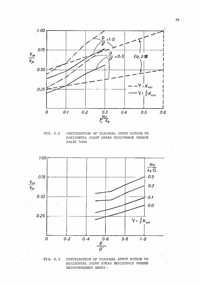
Vch Vjh
1· 00 r-----,.------,-----:-----.---,..---~
0.75 /
0·50
0 o.t 0·2 Q.J Nu
r:Au
Eq.2.'fB
---- ----
Q.4 0.5
FIG. 6.2 CONTRIBUTION OF DIAGONAL STRUT ACTION TO HORIZONTAL JOINT SHEAR RESISTANCE VERSUS AXIAL LOAD
f.QQ
0·75
o.so
0-25
0 Q.2 Q.4 0.6 p p'
Nu Auf~
o.J
0-2
o.t o.o
o.a f.O
FIG. 6.3 CONTRIBUTION OF DIAC~NAL STRUT ACTION TO HORIZONTAL JOINT SHEAR RESIST~.NCE VERSUS
REINFORCEME'NT RATIO i
0·6
79
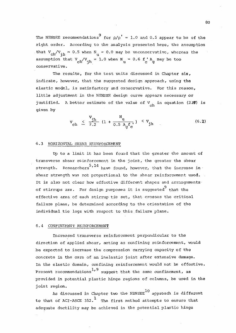
The NZNSEE recommendations9 for p/p 1 = 1.0 and 0.5 appear to be of the
right order. According to the analysis presented here, the assumption
that V h/V.h = 0.5 when N = 0.0 may be unconservative, whereas the c J u
assumption that V h/V 'h = 1. 0 when N = 0. 6 f 1 A may be too c J u c g
conservative.
The results, for the test units discussed in Chapter six,
indicate, however, that the suggested design approach, using the
elastic model, is satisfactory and conservative. For this reason,
little adjustment in the NZNSEE design curve appears necessary or
justified. A better estimate of the value of Vch in equation (2JJ) is
given by
eo
< N
u (l + 0.5 A f I
g c (6.1)
6. 3 HORIZONTAL SHEAR REINFORCEMENT
Up to a limit it has been found that the greater the amount of
transverse shear reinforcement in the joint, the greater the shear 5 14
strength. Researchers ' have found, however, that the increase in ·
shear strength was not proportional to the shear reinforcement used.
It is also not clear how effective different shapes and arrangements 9
of stirrups are. For purposes it is suggested that the
effective area of each stirrup tie set, that crosses the critical
failure plane, be determined according to the orientation of the
individual tie legs with respect to this failure plane.
6. 4 CONFINEMENT REINFORCEMENT
Increased transverse reinforcement perpendicular to the
direction of applied shear, acting as confining reinforcement, would
be expected to increase the compression carrying capacity of the
concrete in the core of an inelastic joint after extensive damage.
In the elastic domain, confining reinforcement would not be effective.
Present recommendations 1' 9 suggest that the same confinement, as
provided in potential plastic hinge regions of columns, be used in the
joint region. 10
As discussed in Chapter two the NZNSEE approach is different
to that of ACI-ASCE 352. 1 The first method attempts to ensure that
adequate ductility may be achieved in b~e potential plastic hinge
81
region, and considers such variables as the level of axial load on the
column, the longitudinal steel ratio, the proportion of the column
section confined, and the stress-strain relationship of the longitudinal
steel and the confined concrete. The second method is based on
preserving the axial load strength of the column after the cover
concrete has spalled.
6.5 INTERSECTING BEAMS AT THE JOINT
Intersecting beams, perpendicular to the direction of applied
shear, may aid confinement of the joint core. The ACI-ASCE 3521
approach is to increase the allowable concrete shear stress in the
joint by 40% where the intersecting beams cover sufficient are a of the
joint region. This is applicable to both Type 1 and Type 2 joints.
The NZNSEE9 approach is to consider increased confinement from
the transverse beams only when no yielding of the beam reinforcement
in these transverse beams is likely. If this is the case, then the
confinement reinforcement required10 may be reduced by one half, where
there is sufficient coverage of the joint by the beams.
It is not suggested that any significant increase in the
proportion of the total joint shear carried by the concrete will occur
in an elastic joint confined by beams. The compression field in a
joint responding elastically is relatively lowly stressed. No
alteration to the joint shear mechanisms, djscussed in Chapter three,
appears to be justified.
6.6 VERTICAL SHEAR REINFORCEMENT
The use of vertical shear reinforcement would, within limits,
increase the shear strength of a joint. The reinforcement may be
provided by intermediate column bars p~portioned to resist forces in
addition to flexural requirements. Special bars passing through the
joint and adequately anchored outside the joint region, or vertical
stirrup ties, may be used as vertical shear reinforcement.
It appears that no experimental work has been done on beam
column join·ts with intentionally designed vertical shear reinforcement.
Therefore calculations for the amount of vertical shear reinforcement
required lack expe!rimental basis. Where column reinforcement passes
through a joint, it is difficult to isolate the components of the bar
force.. one corqponent being the flexural bar force transferred across
the joint, the other results from vertical shear in the joint.
H t hlB th ' . f b owever, presen researc at e Un~vers~ty o Canter ury
investigated the effect of intermediate column bars on the seismic
behaviour of beam-column joints. These test units consisted of
prestressed beams and reinforced concrete columns. The inclusion of
intermediate column bars appeared to result in a dramatic improvement
in joint performance compared to similar units previously tested15
with no intermediate bars.
6. 7 RELATIVE AND ABSOLUTE QUANTITIES OF BEAM TOP
AND BOTTOM REINFORCEMENT
The relative quantity of beam top and bottom reinforcement
(p/p'} may be expected to influence the behaviour o~ an elastic joint.
This can be explained with reference to the elastic model reviewed
in Chapter three. It is evident that the diagonal concrete strut
(Fig. 3.2) is a more efficient mechanism for shear transfer than the
truss mechanism (Fig. 3.3) of the joint core. With reference to
Fig. 3.2, for equal quantities of beam top and bottom reinforcement,
the internal concrete compression forces at ultimate in the beam on
either side of the joint are the same, i.e. C C 1· The diagonal c c
concrete strut is formed between the compression zones of the beam
and column sections. If the ratio of top to bottom beam reinforcement
was greater than unity, the value of C ' on the left-hand side of the c
82
joint core would be smaller than the corresponding concrete compression
force C at the right-hand side. With the smaller compression zone, c
in one of the beam sections at the face of the joint core, the force
in the diagonal concrete strut would obviously become smaller. In the
region of the top reinforcement a greater proportion of the horizontal
shear force would need to be carried by the truss mechanism. Therefore
the analysis becomes more indeterminate.
Analyses of the ~prototype beam-column joint, shown in Fig. 6.l(a),
were carried out with the top reinforcement content being kept constant
as indicated in Fig. 6.l(b). However, the bottom to top reinforcement
content ratio (p/p'> was varied from 1.0 to 0.5.
The approach was similar to that described in section 6.2(a).
The new horizontal joint shear carried by the diagonal concrete strut,
V 1
, was calculated from equation (3. 2) and the bond force, !J.T , was C1 C
calculated from equation (6.1). In this y = 2/3 k 1
• . co
With p/p' = 0.5, the beam compression force on the right-hand side
of Fig. 6.l(a) was close to one half of the beam compression force
83
for the corresponding situation with equal top and bottom reinforcement.
The overstrength moment (M ) on that half of the beam-column assembly 0
was also one half of that shown in Fig. 6.1 (a) , as it was assumed
that the bottom reinforcement was at yield, i.e. f = f = 275 MPa. s y
In evaluating the load carried by the diagonal strut, the smaller
of the beam flexural compression forces, i.e. that based on p' < p was
used. From this the proportion of the horizontal shear force assigned
to the concrete mechanism was calculated. It should be noted that all
other properties being equal when PIP' = 0.5, the total horizontal joint
shear force is approximately three quarters the total horizontal joint
shear force with p/p' = 1.0.
The axial load was varied as in section 6.2(a) for each value of
p/p'. The plots of Vch/Vjh versus PIP' are shown in Fig. 6.3. It can
be seen that for p/p' = 0.5, with zero axial load, the value of Vch/Vjh
is 54% of the value for PIP' = 1.0. The above approach for
determining the value of Vch is likely to be conservative.
The absolute quantity of beam reinforcerrent has been shown to .
be significant in beam-column joint units responding inelastically in
the joint core. Unless the flexural tension reinforcement content
in the plastic hinge regions of beams is kept small, i.e. less than
approximately 1.5%, the horizontal joint stirrup reinforcement required
can result in serious congestion of the joint. The problem of bar slip
can also arise. With an elastic joint, the transfer of bond forces is
much more favourable and less joint reinforcement is required. This
would enable a greater quantity of beam steel to be used through
the joint.
6.8 JOINT ASPECT RATIO
Tests on deep beams with span/depth ratios less than 2, where
arch action is the dominant mode of shear resistance, have indicated
that as the span/depth ratio becomes smaller the shear strength of the
reinforced conc:r.·ete beam increases. In investigations of beam-column
joints, few researchers appear to have tested units with different
· · t1 · · f 5
h aspect ratios. Me~nhe~t and Jirsa of 1e Un~vers~ty o Texas ave
reported tests on beam-column joint units with two different aspect
ratios. The aspect ratio for these tests was defined as he~' where
h0
is the depth of the column, and ~ is the depth of the beam,
both measured in the plane of the applied beam shear. The aspect
ratios used by them were 0.72 and 1.0. Meinheit and Jirsa report
that the aspect ratio did not appear to have affected the ultimate
shear strength of the test units although the units with the smaller
aspect ratios, and greater column width, generally had a greater
shear capacity after the completion of four inelastic cycles.
84
In an elastic joint, a decrease in the aspect ratio would appear
to be accompanied by an increase in the angle of inclination, S, of the
concrete shear resisting mechanism (Fig. 3.2) • This assumes that the
internal forces and the zones of compression acting at the joint
boundary remain unchanged. This increase in inclination would require
a greater contribution from the horizontal force (C + /j,T * - v ) c c col
(Fig. 3. 6) to maintain equilibrium, implying the horizontal joint shear
carried by the concrete mechanism would increase.
Calculations were done for several elastic beam-column joints,
using the loading system in Fig. 6.l(d), with different joint aspect
ratios, to determine the effect on the horizontal component, Vch' of
the diagonal concrete strut. The aspect ratio of the beam-column joint
was defined in terms of the joint core dimensions ash ./h ., where C] b]
h . is the length of the joint core between the centre of reinforcement CJ
in the compression face of the column and the centre of reinforcement
in the tension face. The depth of the joint core ~j is the correspond
ing beam depth between centres of beam reinforcement. The ratio of the
core to overall dimensions, defined ash ./hand hb./hb, was taken as OJ C J
0.8. The ratio of the amount of top to bottom flexural reinforcement
in the example beam was taken as being equal. The area of the beam
reinforcement was the same for every beam section (A = A ' = 2510 mm2
s s as in Fig. 6.1(b)).
The axial load on the column section was zero and the beam
overstrength moment, M , was such that f = f = 275 MPa at the column 0 s y
face. From equilibrium of the system (Fig. 6.l(d)) the appropriate
column moment on the section at the beam face could be found. The
design moment for the critical column section was derived from M (see 0
section 7 .2), so that the ideal strength of the column section
corresponded with approximately 1. 65 times the overstrength capacity
of the critical beam section.
The joint shown in Fig. 6.l(a) has an aspect ratio of 1.2.
For this analysis the aspect ratios were chosen so that 0.5 <h ./hb.< 2.0. CJ J
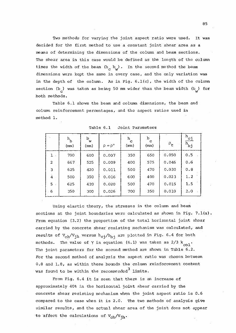
85
Two methods for varying the joint aspect ratio were used. It was
decided for the first method to use a constant joint shear area as a
means of determining the dimensions of the column and beam sections.
The shear area in this case would be defined as the length of the column
times the width of the beam (h b ) • In the second method the beam c w
dimensions were kept the same in every case, and the only variation was
in the depth of the column. As in Fig. 6.l(c), the width of the column
section (b ) was taken as being 50 mm wider than the beam width (b ) for c w
both methods.
Table 6.1 shows the beam and column dimensions, the beam and
column reinforcement percentages, and the aspect ratios used in
method 1.
Table 6.1 Joint Parameters
hb b h b h _Ej_ w c c
pt hbj (mm) (mm) p =p' (mm) (mm)
1 700 600 0.007 350 650 0.050 0.5
2 667 525 0.009 400 575 0.046 0.6
3 625 420 0.011 500 470 0.030 0.8
4 500 350 0. 016 600 400 0.02 3 1.2
5 625 420 0.020 500 470 o. 015 1.5
6 350 300 0.026 700 350 0.010 2.0
Using elastic theory, the stresses in the column and beam
sections at the joint boundaries were calculated as shown in Fig. 7.l(a).
From equation (3.2) the proportion of the total horizontal joint shear
carried by the concrete shear· resisting mechanism was calculated, and
results of Vch/Vjh versus hcj/hbj are plotted in Fig. 6.4 for both
methods. The value of yin equation (6.1) was taken as 2/3 k 1
. co
The joint parameters for the second method are shown in Table 6.2.
For the second method of analysis the aspect ratio was chosen between
0.8 and 1.8, as within these bounds the colwnn reinforcement content
was found to be within the recommended3 limits.
From Fig. 6.4 it is seen that there is an increase of
approximately 40% in the horizontal joint shear carried by the
concrete shear resisting mechanism when the joint aspect ratio is 0.6
compared to the case when it is 2.0. The two methods of analysis give
similar results, and the actual shear area of the joint does not appear
to affect the calculations of Vch/Vjh•
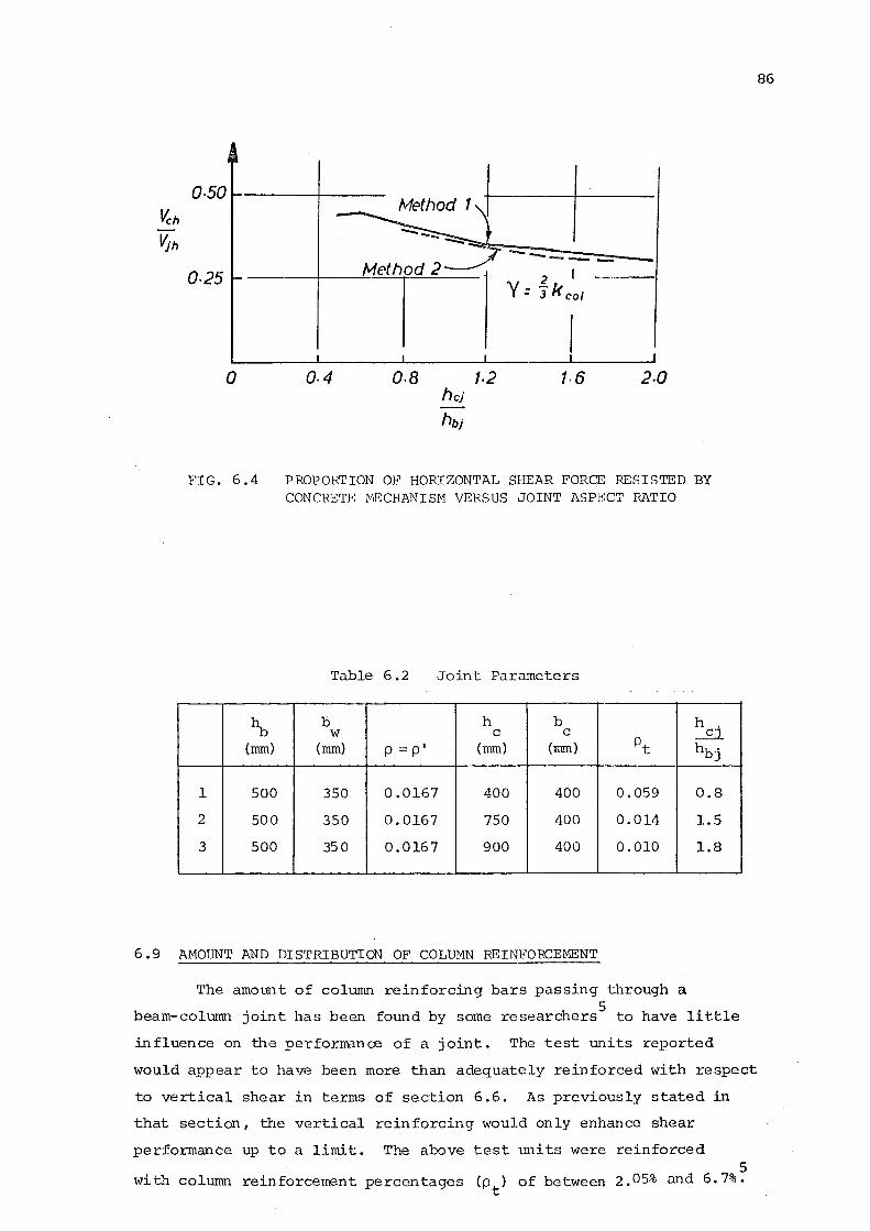
o.so
0·25
0
FIG. 6.4
~ (rom)
1 500
2 500
3 500
Method 1 +-1----+----
0·4 o.a 1·2 1·6 2.0
PROPORTION OF HORIZONTAL SHEAR FORCE RESISTED BY CONCRETE ~lliCHANISM VERSUS JOINT ASPECT RATIO
Table 6.2 Joint Parameters
b h b h w c c _rt
(rom) p = p' (rom) (rom) pt hbj
350 0.0167 400 400 0.059 0.8
350 0.0167 750 400 0.014 1.5
350 0.0167 900 400 0.010 1.8
6.9 AMOUNT AND DISTRIBUTION OF COLUMN REINFORCEMENT
The amount of column reinforcing bars passing through a 5
beam-column joint has been found by some researchers to have little
influence on the performance of a joint. The test units reported
would appear to have been more than adequately reinforced with respect
to vertical shear in terms of section 6.6. As previously stated in
that section, the vertical reinforcing would only enhance shear
performance up to a limit. The above test units were reinforced 5
with column reinforcement percentages (pt) of between 2.05% and 6.7%.
86
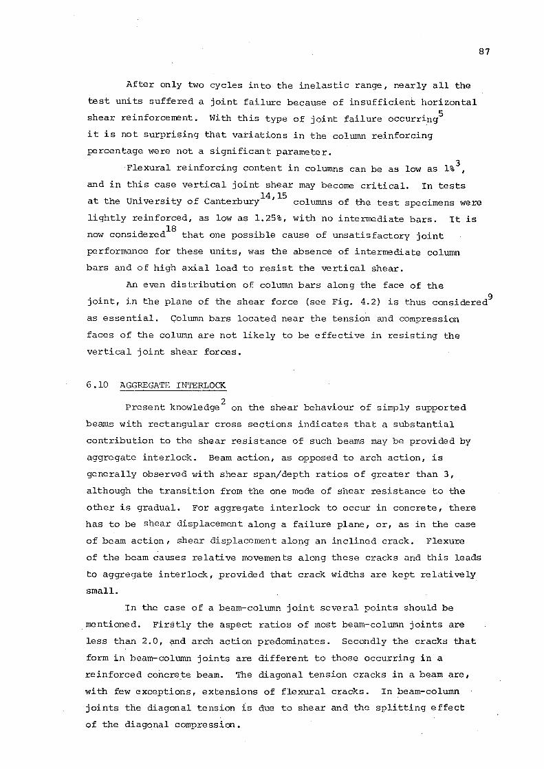
After only two cycles into the inelastic range, nearly all the
test units suffered a joint failure because of insufficient horizontal
shear reinforcement. With this type of joint failure occurring5
it is not surprising that variations in the column reinforcing
percentage were not a significant parameter. 3 Flexural reinforcing content in columns can be as low as l% ,
87
and in this case vertical joint shear may become critical. In tests 14 15
at the University of Canterbury ' columns of the test specimens were
lightly reinforced, as low as 1.25%, with no intermediate bars. It is 'd dl8 . . now cons1 ere that one poss1ble cause of unsat1sfactory joint
performance for these units, was the absence of intermediate column
bars and of high axial load to resist the vertical shear.
An even distribution of column bars along the face of the
joint, in the plane of the shear force (see Fig. 4.2) is thus considered9
as essential. Column bars located near the tension and compression
faces of the column are not likely to be effective in resisting the
vertical joint shear forces.
6 .10 AGGREGATE INTERLOCK
2 Present knowledge on the shear behaviour of simply supported
beams with rectangular cross sections indicates tha·t a substantial
contribution to the shear resistance of such beams may be provided by
aggregate interlock. Beam action, as opposed to arch action, is
generally observed with shear span/depth ratios of greater than 3,
although the transition from the one mode of shear resistance to the
other is gradual. For aggregate interlock to occur in concrete, there
has to be shear displacement along a failure plane, or, as in the case
of beam action, shear displacement along an inclined crack. Flexure
of the beam causes relative movements along these cracks and this leads
to aggregate interlock, provided that crack widths are kept relatively
small.
In the case of a beam-column joint several points should be
mentioned. Firstly the aspect ratios of most beam-column joints are
less than 2.0, and arch action predominates. Secondly the cracks that
form in beam-column joints are different to those occurring in a
reinforced concrete beam. The diagonal tension cracks in a beam are,
with few exceptions, extensions of flexural cracks. In beam-column
joints the diagonal tension is due to shear and the splitting effect
of the diagonal compression.
For aggregate interlock to occur, a relative displacement along
these diagonal cracks would be needed and it is not evident that
this would eventuate.
88
The shear forces introduced to the boundaries of the joint are
as indicated in Figs 3.2 and 3.3. No shear displacement along the
potential failure plane appears possible unless distortions, other than
those due to pure shear, of the joint core at the boundaries occur.
In joints responding inelastically to cyclic loading, deterioration of
the joint core may be caused by yielding of the joint reinforcement.
Uneven bearing of the concrete, after the closure of the cracks, may
lead to relative shear displacements causing some aggregate interlock.
In an elastic joint it is suggested that the shear displacement
along the diagonal cracks that run approximately parallel to the
potential failure plane is negligible and aggregate interlock is
insignificant.
6 . 11 DO'VJEL ACTION
Dowel action has also been identified as one of the shear
resisting mechanisms in beams. For dowel action to occur in a
beam-column joint shear dispacements, transverse to the bars passing
through the joint, are required. The occurrence of shear displacement
along a shear failure plane, as discussed in section 6.10, may be
sufficient to provide some dowel action. A more significant source
of transverse displacement, affecting both the column bars, beam bars,
and also the horizontal stirrup ties, is possible when the diagonal
cracks open up (Fig. 6.5). The magnitude of the horizontal and vertical
components of this diagonal displacement depends upon the angle of
inclination of the crack. For column bars intersecting these cracks
the horizonta-l component of the diagonal crack will induce a transverse
shear displacement in the joint core. This may be accompanied by a
kinking of the column bars across the crack (Fig. 6.5). The beam bars
and horizontal stirrup ties may also be sUbject to dowel shear when a
transverse shear displacement is produced from the vertical component
of the diagonal crack.
Such dowel action may be a major source of shear resistance
when all the other sources are exhausted, i.e. when yield of the joint
reinforcement and deterioration of the diagonal concrete strut have
taken place.
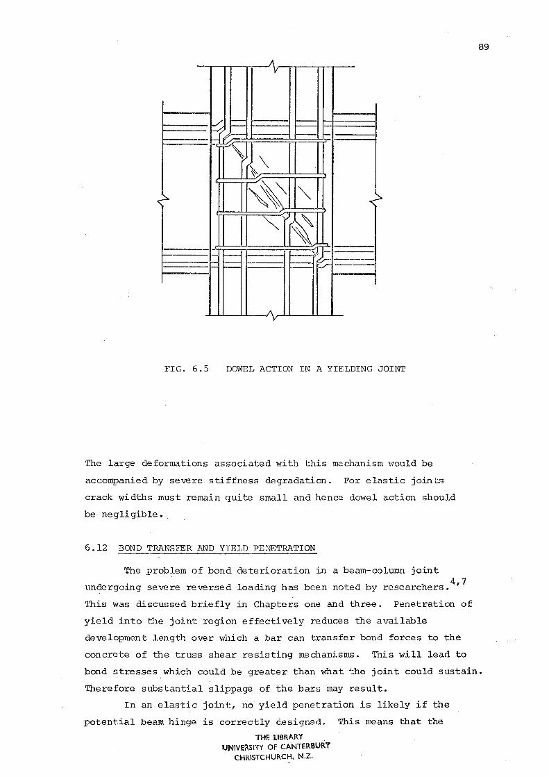
~~ 1-1-
JN~\ 1- -
~
"~ "" "\~
"" - f--)'~--- ,_ i- ~ -~ -
FIG. 6.5 DOWEL ACTION IN A YIELDING JOINT
The large deformations associated with this mechanism \':ould be
accompanied by severe stiffness degradation. For elastic joints
crack widths must remain quite small and hence dowel action should
be negligible •.
6 .12 BOND TRANSFER AND YIELD PENETRATION
The problem of bond deterioration in a beam-column joint 4 7
undergoing severe reversed loading has been noted by researchers. '
89
~bis was discussed briefly in Chapters one and three. Penetration of
yield into the joint region effectively reduces the available
development length over which a bar can transfer bond forces to the
concrete of the truss shear resisting mechanisn~. This will lead to
bond stresses_which could be greater than what t.he joint could sustain.
Therefore substantial slippage of the bars may result.
In an elastic joint, no yield penetration is likely if the
potential beam hinge is correctly C.esigned. This means that the
THE I..IBRARY UNIVE~SITY OF CANTERBURY
CHRISTCHURCH, N.Z.

probable development length for beam bars would extend from the
centroid of the column reinforcement in the tension face to the
concrete compression face. The compression bar forces in the beam
are lower than in the corresponding inelastic case because the beam
concrete compression force at the joint boundary is maintained.
The aspect ratio may influence the bond transfer in an elastic
joint. A reduction in the column width (i.e. smaller aspect ratio)
may reduce the available development length to such an extent that
the problem of bar slip may become critical.
6. 13 DIAMETER OF BEAM AND COLUMN BARS
90
The diameter of beam and column bars is likely to influence the
shear resistance of the joint. No study of this issue appears to have
been made. Smaller bars are known to be more satisfactory for bond
transfer than larger bars. A larger number of both beam and column bars
of small diameter, spaced evenly across the respective beam and column
faces at the joint, will probably lead to a more efficient introduction
of shear stresses into the joint core than several large diameter beam
or column bars. However, this practice would aggravate construction
difficulties.
6.14 SPECIAL JOINT STEEL DEVICES
The possibility of using special joint steel devices has been 8 investigated by some researchers as a means of improving joint behaviour
under inelastic actions. The use of a bond plate to transfer the shear
forces directly to a diagonal concrete strut has been mentioned in
section 1.2. Other proposals such as the utilisation of diagonal bars
across the jqint to transfer the shear forces have also been considered.
Both concepts would probably involve greater fabrication costs and
would not be necessary if the joint is 'protected' by potential plastic
beam hinges located away from the column face.
CHAPTER SEVEN
CONPARISON OF RESULTS AND OBSERVATIONS
This chapter draws conclusions from the results presented in
Chapter five, and critically examines the theoretical approach
reviewed in Chapter three and utilised in Chapter six.
91
The elastic model uses two shear resisting mechanisms for the
purpose of analysis. These are the diagonal concrete strut mechanism
and the truss mechanism. The elastic model appears to be consistent
with the observed behaviour of the two units tested.
The measured angle of cracking on the surface of the joint in
the test units was similar to the predicted angle of the diagonal strut.
The predicted angle was calculated from equilibriTh~ of internal joint
forces (see Appendix A). However, due to the variation of principal
tensile stresses, which change as the beam load is increased, it does
not follow that the observed crack inclination in the joints of the
test units is the same as the inclination of the diagonal compression
field.
The elastic model indicates how the increased axial load will
result in a diagonal strut of greater width. This appears to be
confirmed by the results of these tests. By observing the load
deflection relationships for the beams, given in Chapter five, it can
be seen that the deflection in unit B2 at the top load of the elastic
cycle was considerably less than in unit Bl. As described in section
5 .1. 3, this appears to be due to the smaller joint distortions in
unit B2. This suggests the joint has become stiffer. Indeed it is not
too difficult to visualise that, of the two postulated shear resisting
mechanisms of the elastic model, the one associated with a single
diagonal corner to corner strut will be the stiffer one. In the truss
mechanism tensile forces, resisted by horizontal a~d vertical joint shear
reinforcement, are involved and these lead to relatively large tensile
strains. This accounts for a relatively smaller stiffness of that system.
The extent to which the column axial load is able to provide a
restraint in the vertical direction of the truss mechanism is unclear.
With reference to Figs 3.1 and 3.3, it appears that the zone of
compression at the boundary of the joint would be able to assist in
92
resisting a proportion of the vertical component of the truss mechanism,
V • It is obvious that column reinforcement passing through the joint sv
near the perimeter of the column section would not be as efficient in
resisting shear as multilegged stirrup ties in the horizontal direction.
The results of the tests are unable to indicate the proportion of the
column bar force that comes from shear resistance in the joint.
The elastic model considers the simple force equilibrium of the
internal forces at the joint. The method does not consider compatibility
of deformations between the concrete strut and the truss mechanism.
This may be significant in elastic joints. The concrete strut is the
stiffer mechanism and if compatibility of deformations was considered,
a greater proportion of the joint shear would be carried by it than a
consideration of force equilibrium would suggest. It is evident that the
diagonal concrete st~~t is a more efficient mechanism for joint shear
transfer. This suggests that the elastic model would give a conservative
estimate of the proportion of joint shear resisted by the two mechanisms.
This appears to be verified by the results of the tests reported in
Chap·ter five.
As the joint stirrup-ties were not fully instrumented, it is
impossible to identify the exact mag1'1itude of the total horizontal
joint shear force resisted by the horizontal shear reinforcement.
However, a reasonable estimate of the likely value of the horizontal
shear carried by the joint shear reinforcement, Vsh' can be made from
the strain readings measured on the outer ties, at the top load of a
load cycle. In unit Bl after twelve cycles, the peak average strain in
the outer joint ties was 53% of the yield strain. As a likely estimate
it may be assumed that the inner ties are strained at 20% above the
value of the outer ties. From the area and the measured yield strength
of the tie, Vsh can be estimated (equation 3.4). The total horizontal
joint shear, Vjh' is calculated in Appendix A for theoretical yield of
the outer layer of beam reinforcement. The beam tip load at the maximum
* load of a cycle, P., was less than the theoretical yield load, P • ~ y
Therefore the value of V h was increased by the ratio of P */P. to s y ~
give a value of Vsh which corresponds with the calculated value for Vjh.
Using equation (3.6) the value for Vch can then be obtained. In this,
the mechanisms of dowel action and aggregate interlock have not been
considered.
at the high
By similar means, estimates of Vch can be made for unit B2
(0.44 f 'A) and at the intermediate axial loads (0.25 f'A ). c g c g
93
The proportions of the total joint horizontal shear resisted by the
concrete mechanisms Vch/Vjh so calculated are shown in Fig. 7.1 for
the respective axial loads. It should be noted that in the evaluation
of Vsh' the contribution of horizontal stirrups was deliberately
overestimated in order not to overestimate the contribution of the
concrete strut, V ch
Higher stirrup strains in unit B2 under large
axial compression may well have resulted from splitting of the concrete
due to large diagonal compression, rather than from the demand on the
truss mechanism for shear transfer.
For comparison, the suggested equation for Vch' obtained
from case studies using the elastic model (equation 6.~), is shown.
This suggests that the elastic model is conservative in the low and
intermediate column axial load regions. At the high axial load
the elastic method appears unconservative, probably because of the
large diagonal compression as discussed above.
It is interesting to compare the performance of unit Bl with
Beckingsale's7 unit Bl2 in the inelastic range. The strength of the
joint of unit Bl2 was maintained so that plastic hinges formed in the
beam at the column face. As described in section 4.4, the horizontal
joint shear at the end of the test of unit Bl2 is very similar to that
occurring at the elastic limit for tmi t Bl. The beam tip load at the
end of the test for unit Bl2, from an average of beam loads, was 145 kN.
The beam loads applied at the elastic limit for unit Bl were 130 kN.
In unit Bl2 with 8 sets of 4 x 12.7 rom ties, only one tie
was observed to yield at the end of the test after three cycles
of ductility 6. The strength of the joint of unit Bl2 was maintained
so that plastic hinges formed in the beam next to the column face.
Near the top of the first cycle at ductility 6, severe slip of the
top and bottom beam bars occurred through the joint. However, in
unit Bl after only two cycles at a ductility of 4, all the ties
had yielded and the average beam tip load dropped by 30% from its
average maximum of 165 kN, reached in the first cycle at ductility 2.
Pull-out of beam bars would have been an unlikely problem in
units Bl and B2 because the joint was gradually failing in shear
or shear compression and this led to rapid reduction of bond forces
to subcritical levels.
To enable unit Bl to fom satisfactory beam hinges at the column
face, it is obvious that more than 8 sets of 4Xl2.7 rom ties would have
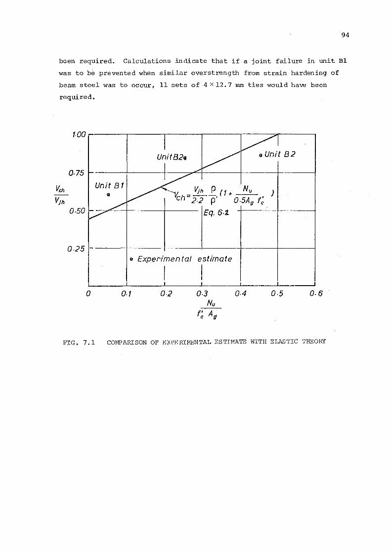
94
been required. Calculations indicate that if a joint failure in unit Bl
was to be prevented when similar overstrength from strain hardening of
beam steel was to occur, 11 sets of 4 x 12. 7 mm ties would have been
required.
f.OO ..... ---.--,-----.------,.-----.------:------~
o.75
Unit B 1 • _ Vjh _e ( 1 + . N u
ch-2.2 p' o.5Ag 0-50 Eq. 6-1
0-25 o Experimen tat estimate
I I 0 0-1 0.2 0-3 o.4
Nu f~ A11
e Unit 82
' ) fc
0-5 0-6
FIG. 7.1 COMPARISON OF EXPERIMENTAL ESTIMATE WITH ELASTIC THEORY
CHAPTER EIGHT
CONCLUSIONS AND RECOMMENDATIONS
Present knowledge of the shear behaviour of reinforced concrete
beams suggests that sophisticated theories or analyses of reinforced
concrete beam-column joints are unlikely to provide a satisfactory
solution. The model postulated provides a simple approach to the
analysis of the shear resisting mechanisms in elastic beam-column
joints. By considering equilibrium of the internal forces acting at
the joint, a proportion of the total joint·shear force may be assigned
to each of the two postulated shear resisting mechanisms. The results
of the two tests indicate that this method of analysis should provide
95
a satisfactory, conservative estimate of the required joint shear
reinforcement in a cyclically loaded elastic joint. The test specimens
performed well with respect to bond and pull-out of beam bars and the
retention of shear strength under cyclic loading in the elastic range·.
A full elastic analysis of a beam-column joint is not suggested
for design. The present recommendations of the New Zealand National
Society for Earthquake Engineering, 9 based on the concepts presented in
the Paulay, Park and Priestley paper,13
appear satisfactory for design
purposes. A minor modification to the NZNSEE equation 2.1~ could be
made. Equation (6.1} is probably more realistic. Further extensions
of the method of analysis for elastic beam-column joints could be made.
However, it is not likely that this would lead to significant change in
the joint shear reinforcement content. Practical considerations with
respect to reinforcement layout would often override any adjustments.
resulting from refinements in analyses.
It is suggested that where relocated potential plastic beam
hinges are employed, a considerable easing of previously encountered
construction difficulties would ensue with a beam-column joint designed
elastically. Indeed this is the reason for relocating plastic beam
hinges away from column faces, a process inevitably involving some burden
in fabricating the beam reinforcement. Unfortunately in many situations
of seismic design, due to confinement restrictions, the construction
benefits of an elastic joint may not be fully utilized. However, where
the axial column compression load is small, confinement requirements
should be less severe. Therefore an elastic beam-column joint with
96
low axial load on the column will require less joint shear reinforcement
than those joints where inelastic deformations occur in immediately
adjacent members.
Similar advantages will result in elastic joints which may be
considered to be confjned by beams framing into the colunm from four
sides, even though they may be carrying significant column compression
loads.
The experimental program indicated that the test units, as
designed, would be unsuitable for dissipation of energy resulting
from severe seismic loading. It is thought that considerable post
elastic strength from other sources, such as dowel ·action ... of the column
bars, was available in thebeam-column joints tested.
The importance of considering vertical as well as horizontal
shear has been emphasised. Future research may be able to provide more
information on the role of vertical shear reinforcement, consisting
of intermediate continuous column bars, in resis'cing joint shear forces.
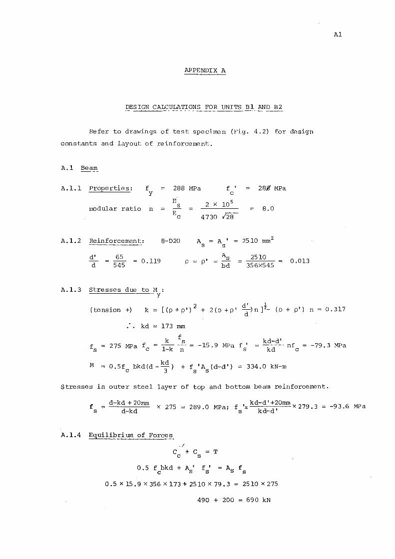
APPENDIX A
DESIGN CALCULATIONS FOR UNITS Bl AND B2
Refer to drawings of test specimen (Fig. 4.2) for design
constants and layout of reinforcement.
A.l Beam
A.l.l Properties: f 288 y
E modular ratio s n
E c
A. l. 2 Reinforcement: 8-D20
d' d
65 545
0.119
A.l.3 Stresses due to M : y
p
MPa
2 X
4730
A s
p'
f I
c
10 5
128
A' s
As
bd
28,2' MPa
8.0
2510 rnrn 2
2510 356><545 = 0.013
(tension +) k 2 d' l
[ ( p + p I ) + 2 ( p + p I -) n ) 2_ ( p + pI ) n d
kd 173 rnrn
k
Al
0.317
275 MPa fc
f s
1-k n -15.9 MPa f'
s kd-d' ---nf
kd c -79.3 MPa
M = 0.5f bkd(d _kd) + f 'A (d-d') = 334.0 kN-m c 3 s s
Stresses in outer steel layer of top and bottom beam reinforcement.
f s =
d-kd + 20rnrn d-kd
X 275 289 0 M f 1- kd-d 1
+ 20rnrn X 279 3 = -93.6 MPa · Pa; s - kd-d' ·
A.l.4 Equilibrium of Forces
~f
C + C = T c s
0 • 5 f bkd + A I f I c s s
0.5Xl5.9X356Xl73+2510X79.3 = 2510X275
490 + 200 = 690 kN
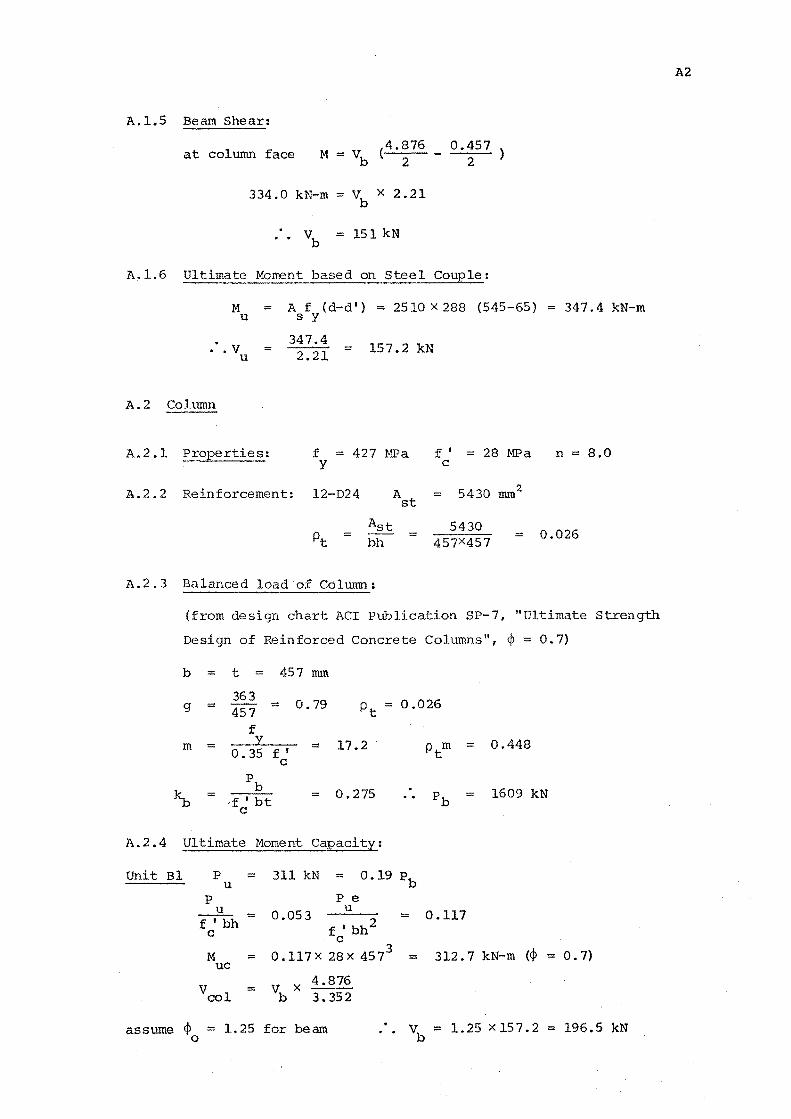
A.l.5 Beam Shear:
at column face M == V (4.876 b 2
334.0 kN-m == vb x 2.21
= 151 kN
0.457 2
A.l.6 Ultimate Moment based on Steel Couple:
M = A f (d-d 1) = 2510 X 288 (545-65) = 347.4 kN-m
u s y
347.4 .v = u 2.21 157.2 kN
A.2 Column
A.2.1 Properties: f = 427 MPa y
A.2.2 Reinforcement: l2-D24 A8
t
Ast =
bh
A.2.3 Balanced load o£ Column:
f I == 28 MPa n = 8.0 c
== 5430 mmz
5430 0.026 = 457X457
(from design chart ACI Publication SP-7, "Ultimate Strength
Design of Reinforced Concrete Columns", <P 0. 7)
b == t = 457 mm
363 0. 79 0.026 g = = Pt =
7 f
m = = 17.2 ptm = 0.448 o. 35 f I
c
~ pb
0.275 1609 kN = ·f I bt pb c
A.2.4 Ultimate Moment Capacity:
Unit Bl p = 311 kN = 0.19 pb u
p P e u 0.053
u 0.117
f I bh = = f I bh2
c . c
M = O.ll7X 28X 4573 = 312.7 kN-m (<jl = 0. 7)
uc
v vb X 4.876
= col 3. 352
assume <1> 0
= 1. 25 for be am vb = 1.25 x 15 7. 2 196.5 kN
A2
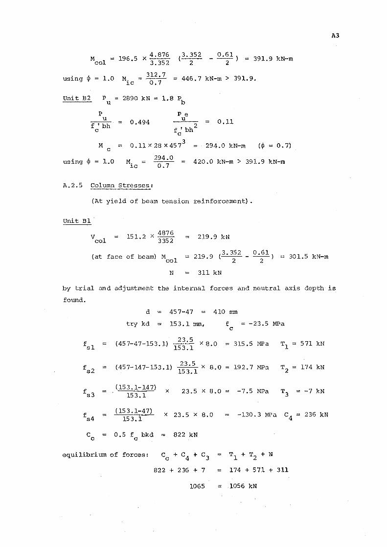
M = 196.5 X 4. 876 (3.352 - 0.61) = 391.9 kN-m col 3.352 2 2
using 4> = 1.0 M. 312.7 = 446.7 kN-m > 391. 9. = 0.7
unit B2 p :::: u
p u
f I bh = c
M = c
~c
2890 kN =
0.494
1.8 pb
Pe u
f I bh 2 c
0 .11 X 28 X 45 73 =
= 0.11
294.0 kN-m (<j> = 0. 7)
using 4> = 1.0 M. ~c
294.0 0.7
420.0 kN-m > 391.9 kN-m
A.2.5 Column Stresses:
Unit Bl
(At yield of beam tension reinforcement}.
veal = 151 2 X 4876
• 3352
(at face of beam) M col
= 219.9 kN
N = 311 kN
301.5 kN-m
A3
by trial and adjustment the internal forces and neutral axis depth is
found.
d = 457-47 = 410 rom
try kd = 153.1 mm, f c
-23.5 MPa
fsl (457-47-153.1) 1~~:~ X 8.0 = 315.5 MPa T1 = 571 kN
fs2 (457-147-153.1) 2 5 X 8.0 192.7MPa T2 174 kN = = = 153.1
fs3 = (153.1-147) X 23.5 X 8,0 = -7.5 MPa T3 = -7 kN
153.1
fs4 = ( 15 3.1-4 7) X 23.5 X 8.0 = -130.3 MPa c4 = 236 kN
153.1
c = 0.5 f bkd = 822 kN c c
equilibrium of forces: c + c4 + c3 = T1 + T2 + N c
822 + 236 + 7 = 174 + 571 + 311
1065 ~ 1056 kN
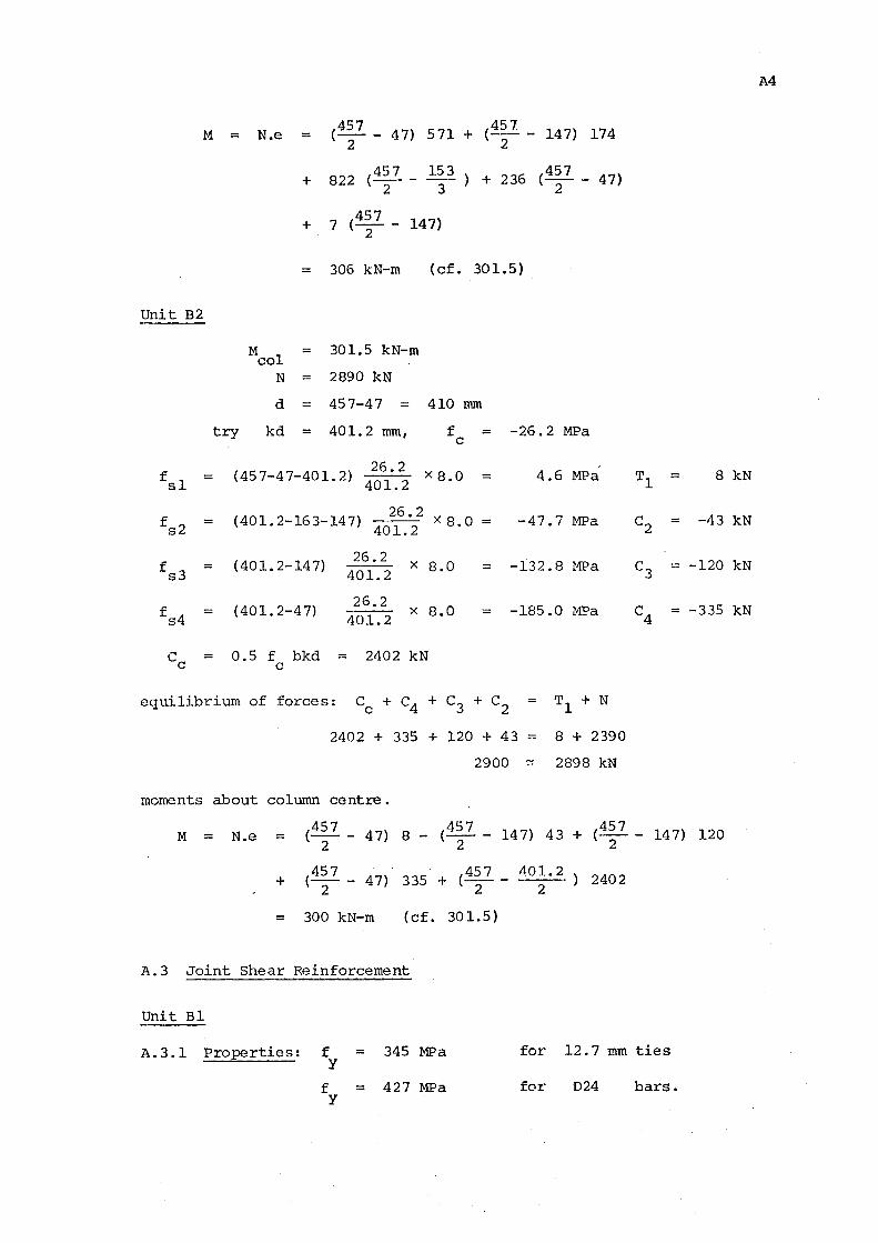
M = N.e = (457 - 47) 571 + (i57 - 147) 174
2 2
+ 822 (457 - 153 ) + 236 (457 - 47) 2 3 2
+ 7 (457
- 147) 2
306 kN-m (cf. 301.5)
Unit B2
f
f
= sl
::: s2
M ::: 301.5 kN-m col
N ::: 2890 kN
d ::: 457-47 = 410 mm
try kd ::: 401.2 mm, f c
(45 7-4 7-401. 2) 26.2
X 8.0 401.2
( 401. 2-16 3-14 7) 26.2 X
401.2 8 '0
(401. 2-14 7)
(401.2-47)
26.2 401.2
26.2 401.2
X 8.0
X 8.0
C = 0.5 f bkd = 2402 kN c c
= -26.2 MPa
= 4.6 MPa
= -47.7 MPa
-132.8 MPa
-185.0 MPa
equilibrium of forces: Cc + c 4 + C3 + c2
= Tl + N
2402 + 335 + 120 + 43 -- 8 + 2390
2900 ~ 2898 kN
moments about column centre.
Tl = 8 kN
c2 = -43 kN
-120 kN
= -335 kN
M = N.e = ( 4~ 7 - 47) 8- ( 4~ 7 - 147) 43 + ( 4~ 7 - 147) 120
+ (457 - 47) 335 + (457 - 401.2 2 2 2
2402
= 300 kN-m (cf. 30 1.5}
A.3 Joint Shear Reinforcement
Unit Bl
A.3.1 Properties: f = 345 MPa y
for 12.7 mm ties
f = 427 MPa for D24 bars. y
A4
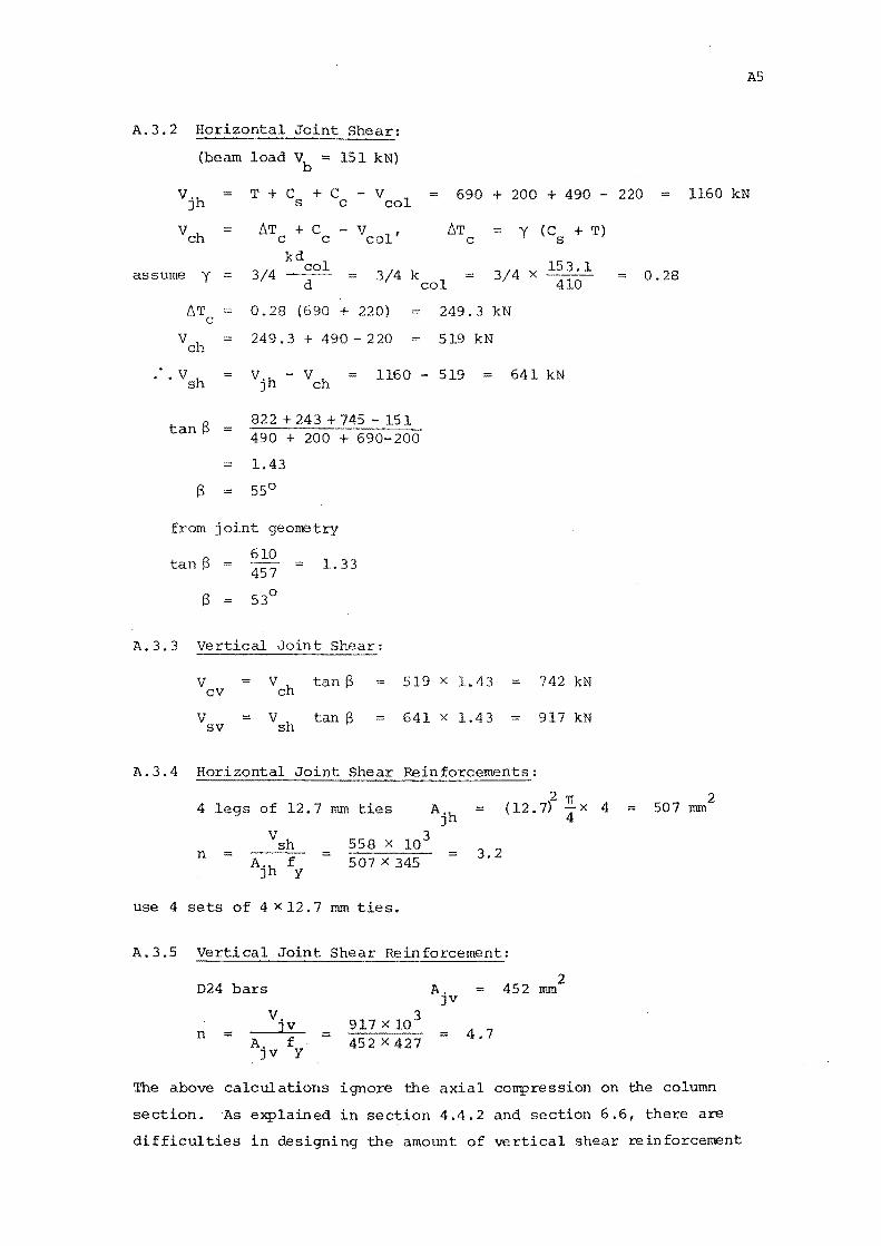
AS
A.3.2 Horizontal
(beam load Vb = 151 kN}
vjh T+C +C -V s c col 690 + 200 + 490 - 220 1160 kN
vch = I:.T + C c c - v col'
I:.T c
y (C + T} s
assume y kd
314 col d 3/4 kcol 3/4 X l~~; l
/:,T c
0.28 (690 + 220) ~ 249.3 kN
vch 249.3 + 490-220 519 kN
. · vsh . 1160 519 ~ 641 kN
tanS = 822 +243 +745 -151 490 + 200 + 690-200
1.43
s = 55°
from joint georretry
tanS := 610 457
1. 33
A. 3. 3 Vertical Joint Shear:
v vch tanS cv
v vsh tanS sv
519 X
641 X
1.43
1.43
A.3.4 Horizontal Joint Shear Reinforcements:
742 kN
917 kN
4 legs of 12.7 mm ties Ajh (12. 7)2 ~X
vsh 558 X 103
3.2 n = A.h f 507 X 345
J y
use 4 sets of 4 x 12.7 mm ties.
A.3.5 Vertical Joint Shear Reinforcement:
024 bars 452 2
A. mm JV
v. 3 n = JV = 4.7
A. f 452 X 427 JV y
4
0.28
507 2
= mm
The above calculations ignore the axial compression on the column
section. As explained in section 4.4. 2 and section 6 .6, there are
difficulties in designing the amount of vertical shear reinforcement
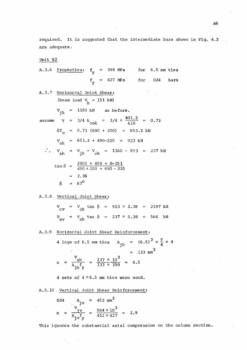
A6
required. It is suggested that the intermediate bars shown in Fig. 4.2
are adequate •
Unit B2
A. 3.6 P rope rtie s : f = 398 MPa for 6.5 mm ties y
f = 427 MPa for 024 bars y
A. 3. 7 Horizontal Joint Shear:
(beam load v = b
151 kN)
vjh = 1160 kN as before.
3/4 k 1 3/4 X 401.2
0.73 assume y = = co 410
f1T 0.73 (690 + 200) = 653.2 kN c
vch = 653.2 + 490-220 = 923 kN
vsh = vjh - vch 1160 - 923 = 237 kN
tan 13 2402 + 498 + 8-151 490 + 200 + 690- 220
= 2.38
s = 67°
A.3.8 Vertical Joint Shear;
A. 3.9
A. 3.10
Vcv = Vch tan S
vsv = vsh tan S
923 X 2.38 = 2197 kN
237 X 2.38 564 kN
Horizontal Joint Shear Reinforcement:
4 legs of 6.5 mm ties Ajh = (6 .5) 2 X 'IT X 4
133 2
= nun
vsh 237 X 103
4.5 n = = = A,hf 133 X 398 J y
4 sets of 4 X 6.5 nun ties were used.
Vertical Joint Shear Reinforcement:
024 A, = 452 nun2 JV
v. 564 X 103 n = JV = = 2.9
A. f 452 X 427 JV y
4
This ignores the stmstantia1 axial compression on the column section.
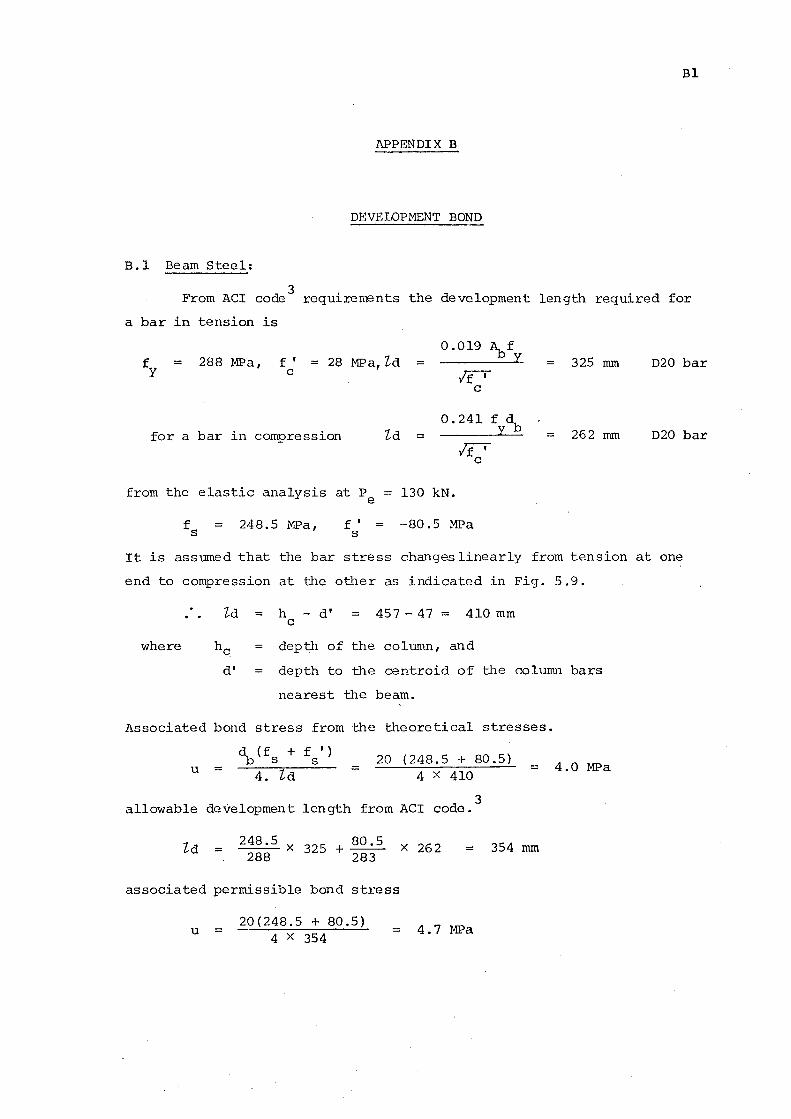
Bl
APPENDIX B
DEVELOPMENT BOND
B.l Beam Steel:
3 From ACI code requirements the development length required for
a bar in tension is
= 288 MPa, f ' = 28 MP a, ld = c
0.019 A f - b y
If'
for a bar in compression
from the elastic analysis at P e
fs = 248.5 MPa, f' s
ld
c
0.241 f d yb
If' c
130 kN.
-80.5 MPa
325 mm D20 bar
= 262 mm D20 bar
It is assumed that the bar stress changeslinearly from tension at one
end to compression at the other as indicated in Fig. 5.9.
where
ld = h - d' c 457-47 = 410mm
depth of the column, and
d' = depth to the centroid of the column bars
nearest the beam.
Associated bond stress from the theoretical stresses.
u = = 20 (248.5 + 80.5)
4 X 410
3 allowable development length from ACI code.
= 4.0 MPa
ld = 248.5 X 325 + 80.5 X 262 = 354 mm 288 283
associated permissible bond stress
u = 20(248.5 + 80.5)
4 X 354 = 4.7 MPa
B .1. 1 Unit Bl
(from Fig. 5.9) at cycle 15 ~ = 4
fs = 300 MPa
f 1 = -260 MPa s
gauge location 7
gauge location 4
B2
the stress transfer is approximately linear between these two points.
Maximum possible development length 'ld = 400 mm
associated bond stress u = 20 ( 300 + 260) 4 X 300
B.l.2 Unit B2
(from Fig.5.12) at cycle 23 ~ = 4
fs = 288 MPa
f 1 = -130 MPa s
gauge location 7
gauge location 3
= 9.3 .MPa
the stress transfer is approximately linear between these two points.
Maximum possible development length 'ld = 400 mm
20 ( 288 + 130) associated bond stress u =
4 X 400 = 5.0 MPa.
Classn:
ELASTIC BEHAVIOUR OF EARTHQUAKE RESISTANT
REINFORCED CONCRETE INTERIOR BEAM-COLUMN JOINTS
G. Birss
ABSTRACT: Results are presented of tests of two interior
beam-column joints under simulated earthquake loading.
The elastic behaviour was investigated. The units were
then tested until failure. An elastic model was reviewed
and was found to provide a satisfactory and conservative
estimate of joint shear reinforcement required in an
elastic joint. ~he response of these test units was
found to be unsatisfactory in the post-elastic range.
Department of Civil Engineering, University of Canterbury.
Master of Engineering Report.'