the emc team june 17, 2006 - linuxcnc.org · · 2006-09-151.1.1 hal is based on traditional...
TRANSCRIPT
The HAL (Hardware Abstraction Layer) Handbook
The EMC Team
June 17, 2006

1
This handbook is a work in progress. If you are able to help with writing, editing, or graphicpreparation please contact any member of the writing team or join and send an email to [email protected].
Copyright (c) 2000-6 LinuxCNC.org
Permission is granted to copy, distribute and/or modify this document under the terms of theGNU Free Documentation License, Version 1.1 or any later version published by the Free SoftwareFoundation; with no Invariant Sections, no Front-Cover Texts, and one Back-Cover Text: "This HALHandbook is the product of several authors writing for linuxCNC.org. As you find it to be of value inyour work, we invite you to contribute to its revision and growth." A copy of the license is included inthe section entitled "GNU Free Documentation License". If you do not find the license you may ordera copy from Free Software Foundation, Inc. 59 Temple Place, Suite 330 Boston, MA 02111-1307

Contents
I Introduction & Tutorial 8
1 Introduction 91.1 What is HAL? . . . . . . . . . . . . . . . . . . . . . . . . . . . . . . . . . . . . . . . . . . . . 9
1.1.1 HAL is based on traditional system design techniques . . . . . . . . . . . . . . . . 9
1.1.1.1 Part Selection . . . . . . . . . . . . . . . . . . . . . . . . . . . . . . . . . . . 9
1.1.1.2 Interconnection Design . . . . . . . . . . . . . . . . . . . . . . . . . . . . . 9
1.1.1.3 Implementation . . . . . . . . . . . . . . . . . . . . . . . . . . . . . . . . . . 10
1.1.1.4 Testing . . . . . . . . . . . . . . . . . . . . . . . . . . . . . . . . . . . . . . . 10
1.1.2 Summary . . . . . . . . . . . . . . . . . . . . . . . . . . . . . . . . . . . . . . . . . . 10
1.2 HAL Concepts . . . . . . . . . . . . . . . . . . . . . . . . . . . . . . . . . . . . . . . . . . . 10
1.3 HAL components . . . . . . . . . . . . . . . . . . . . . . . . . . . . . . . . . . . . . . . . . . 12
1.3.1 External Programs with HAL hooks . . . . . . . . . . . . . . . . . . . . . . . . . . . 12
1.3.2 Internal Components . . . . . . . . . . . . . . . . . . . . . . . . . . . . . . . . . . . 12
1.3.3 Hardware Drivers . . . . . . . . . . . . . . . . . . . . . . . . . . . . . . . . . . . . . 13
1.3.4 Tools and Utilities . . . . . . . . . . . . . . . . . . . . . . . . . . . . . . . . . . . . . 13
1.4 Tinkertoys, Erector Sets, Legos and the HAL . . . . . . . . . . . . . . . . . . . . . . . . . 13
1.4.1 Tower . . . . . . . . . . . . . . . . . . . . . . . . . . . . . . . . . . . . . . . . . . . . 13
1.4.2 Erector Sets . . . . . . . . . . . . . . . . . . . . . . . . . . . . . . . . . . . . . . . . . 13
1.4.3 Tinkertoys . . . . . . . . . . . . . . . . . . . . . . . . . . . . . . . . . . . . . . . . . . 14
1.4.4 A Lego Example . . . . . . . . . . . . . . . . . . . . . . . . . . . . . . . . . . . . . . 14
1.5 Timing Issues In HAL . . . . . . . . . . . . . . . . . . . . . . . . . . . . . . . . . . . . . . . 15
1.6 Dynamic Linking and Configuration . . . . . . . . . . . . . . . . . . . . . . . . . . . . . . 16
2 HAL Tutorial 172.1 Before we start . . . . . . . . . . . . . . . . . . . . . . . . . . . . . . . . . . . . . . . . . . . 17
2.1.1 Notation . . . . . . . . . . . . . . . . . . . . . . . . . . . . . . . . . . . . . . . . . . . 17
2.1.2 Root Privilges . . . . . . . . . . . . . . . . . . . . . . . . . . . . . . . . . . . . . . . . 17
2.1.3 The RTAPI environment . . . . . . . . . . . . . . . . . . . . . . . . . . . . . . . . . . 18
2.2 A Simple Example . . . . . . . . . . . . . . . . . . . . . . . . . . . . . . . . . . . . . . . . . 18
2.2.1 Loading a realtime component . . . . . . . . . . . . . . . . . . . . . . . . . . . . . . 18
2.2.2 Examining the HAL . . . . . . . . . . . . . . . . . . . . . . . . . . . . . . . . . . . . 19
2.2.3 Making realtime code run . . . . . . . . . . . . . . . . . . . . . . . . . . . . . . . . . 20
2.2.4 Changing parameters . . . . . . . . . . . . . . . . . . . . . . . . . . . . . . . . . . . 21
2.2.5 Saving the HAL configuration . . . . . . . . . . . . . . . . . . . . . . . . . . . . . . 22
2.2.6 Restoring the HAL configuration . . . . . . . . . . . . . . . . . . . . . . . . . . . . . 22
2.3 Looking at the HAL with halmeter . . . . . . . . . . . . . . . . . . . . . . . . . . . . . . . . 22
2

CONTENTS 3
2.3.1 Starting halmeter . . . . . . . . . . . . . . . . . . . . . . . . . . . . . . . . . . . . . 232.3.2 Using halmeter . . . . . . . . . . . . . . . . . . . . . . . . . . . . . . . . . . . . . . . 23
2.4 A slightly more complex example. . . . . . . . . . . . . . . . . . . . . . . . . . . . . . . . . 252.4.1 Installing the components . . . . . . . . . . . . . . . . . . . . . . . . . . . . . . . . 252.4.2 Connecting pins with signals . . . . . . . . . . . . . . . . . . . . . . . . . . . . . . . 262.4.3 Setting up realtime execution - threads and functions . . . . . . . . . . . . . . . . 272.4.4 Setting parameters . . . . . . . . . . . . . . . . . . . . . . . . . . . . . . . . . . . . . 292.4.5 Run it! . . . . . . . . . . . . . . . . . . . . . . . . . . . . . . . . . . . . . . . . . . . . 29
2.5 Taking a closer look with halscope. . . . . . . . . . . . . . . . . . . . . . . . . . . . . . . . 292.5.1 Starting Halscope . . . . . . . . . . . . . . . . . . . . . . . . . . . . . . . . . . . . . 292.5.2 Hooking up the “scope probes” . . . . . . . . . . . . . . . . . . . . . . . . . . . . . . 322.5.3 Capturing our first waveforms . . . . . . . . . . . . . . . . . . . . . . . . . . . . . . 332.5.4 Vertical Adjustments . . . . . . . . . . . . . . . . . . . . . . . . . . . . . . . . . . . . 342.5.5 Triggering . . . . . . . . . . . . . . . . . . . . . . . . . . . . . . . . . . . . . . . . . . 342.5.6 Horizontal Adjustments . . . . . . . . . . . . . . . . . . . . . . . . . . . . . . . . . . 362.5.7 More Channels . . . . . . . . . . . . . . . . . . . . . . . . . . . . . . . . . . . . . . . 37
II HAL Reference 38
3 General Reference Information 393.1 Notation . . . . . . . . . . . . . . . . . . . . . . . . . . . . . . . . . . . . . . . . . . . . . . . 39
3.1.1 Typographical Conventions . . . . . . . . . . . . . . . . . . . . . . . . . . . . . . . . 393.1.2 Names . . . . . . . . . . . . . . . . . . . . . . . . . . . . . . . . . . . . . . . . . . . . 39
3.2 General Naming Conventions . . . . . . . . . . . . . . . . . . . . . . . . . . . . . . . . . . 393.3 Hardware Driver Naming Conventions . . . . . . . . . . . . . . . . . . . . . . . . . . . . . 40
3.3.1 Pin/Parameter names . . . . . . . . . . . . . . . . . . . . . . . . . . . . . . . . . . . 403.3.1.1 Examples . . . . . . . . . . . . . . . . . . . . . . . . . . . . . . . . . . . . . 41
3.3.2 Function Names . . . . . . . . . . . . . . . . . . . . . . . . . . . . . . . . . . . . . . 413.3.2.1 Examples . . . . . . . . . . . . . . . . . . . . . . . . . . . . . . . . . . . . . 41
4 Canonical Device Interfaces 424.1 Digital Input . . . . . . . . . . . . . . . . . . . . . . . . . . . . . . . . . . . . . . . . . . . . 42
4.1.1 Pins . . . . . . . . . . . . . . . . . . . . . . . . . . . . . . . . . . . . . . . . . . . . . 424.1.2 Parameters . . . . . . . . . . . . . . . . . . . . . . . . . . . . . . . . . . . . . . . . . 424.1.3 Functions . . . . . . . . . . . . . . . . . . . . . . . . . . . . . . . . . . . . . . . . . . 42
4.2 Digital Output . . . . . . . . . . . . . . . . . . . . . . . . . . . . . . . . . . . . . . . . . . . 424.2.1 Pins . . . . . . . . . . . . . . . . . . . . . . . . . . . . . . . . . . . . . . . . . . . . . 424.2.2 Parameters . . . . . . . . . . . . . . . . . . . . . . . . . . . . . . . . . . . . . . . . . 434.2.3 Functions . . . . . . . . . . . . . . . . . . . . . . . . . . . . . . . . . . . . . . . . . . 43
4.3 Analog Input . . . . . . . . . . . . . . . . . . . . . . . . . . . . . . . . . . . . . . . . . . . . 434.3.1 Pins . . . . . . . . . . . . . . . . . . . . . . . . . . . . . . . . . . . . . . . . . . . . . 434.3.2 Parameters . . . . . . . . . . . . . . . . . . . . . . . . . . . . . . . . . . . . . . . . . 434.3.3 Functions . . . . . . . . . . . . . . . . . . . . . . . . . . . . . . . . . . . . . . . . . . 43
4.4 Analog Output . . . . . . . . . . . . . . . . . . . . . . . . . . . . . . . . . . . . . . . . . . . 434.4.1 Parameters . . . . . . . . . . . . . . . . . . . . . . . . . . . . . . . . . . . . . . . . . 444.4.2 Functions . . . . . . . . . . . . . . . . . . . . . . . . . . . . . . . . . . . . . . . . . . 44

CONTENTS 4
4.5 Encoder . . . . . . . . . . . . . . . . . . . . . . . . . . . . . . . . . . . . . . . . . . . . . . . 44
4.5.1 Pins . . . . . . . . . . . . . . . . . . . . . . . . . . . . . . . . . . . . . . . . . . . . . 44
4.5.2 Parameters . . . . . . . . . . . . . . . . . . . . . . . . . . . . . . . . . . . . . . . . . 45
4.5.3 Functions . . . . . . . . . . . . . . . . . . . . . . . . . . . . . . . . . . . . . . . . . . 45
5 Tools and Utilities 465.1 Halcmd . . . . . . . . . . . . . . . . . . . . . . . . . . . . . . . . . . . . . . . . . . . . . . . 46
5.1.1 Usage . . . . . . . . . . . . . . . . . . . . . . . . . . . . . . . . . . . . . . . . . . . . 46
5.1.2 Options . . . . . . . . . . . . . . . . . . . . . . . . . . . . . . . . . . . . . . . . . . . 46
5.1.3 Commands . . . . . . . . . . . . . . . . . . . . . . . . . . . . . . . . . . . . . . . . . 47
5.1.3.1 Loading/unloading modules . . . . . . . . . . . . . . . . . . . . . . . . . . 47
5.1.3.2 Creating Signals . . . . . . . . . . . . . . . . . . . . . . . . . . . . . . . . . 47
5.1.3.3 Linking things together . . . . . . . . . . . . . . . . . . . . . . . . . . . . . 48
5.1.3.4 Setting Values . . . . . . . . . . . . . . . . . . . . . . . . . . . . . . . . . . 48
5.1.3.5 Configuring Functions and Threads . . . . . . . . . . . . . . . . . . . . . . 49
5.1.3.6 Controlling Realtime Execution . . . . . . . . . . . . . . . . . . . . . . . . 49
5.1.3.7 Viewing the HAL Configuration . . . . . . . . . . . . . . . . . . . . . . . . . 50
5.1.3.8 Saving the HAL configuration . . . . . . . . . . . . . . . . . . . . . . . . . 50
5.2 Halshow . . . . . . . . . . . . . . . . . . . . . . . . . . . . . . . . . . . . . . . . . . . . . . . 50
5.3 Halmeter . . . . . . . . . . . . . . . . . . . . . . . . . . . . . . . . . . . . . . . . . . . . . . 50
5.4 Halscope . . . . . . . . . . . . . . . . . . . . . . . . . . . . . . . . . . . . . . . . . . . . . . 51
6 Hardware Drivers 526.1 Parport . . . . . . . . . . . . . . . . . . . . . . . . . . . . . . . . . . . . . . . . . . . . . . . 52
6.1.1 Installing . . . . . . . . . . . . . . . . . . . . . . . . . . . . . . . . . . . . . . . . . . 52
6.1.2 Removing . . . . . . . . . . . . . . . . . . . . . . . . . . . . . . . . . . . . . . . . . . 53
6.1.3 Pins . . . . . . . . . . . . . . . . . . . . . . . . . . . . . . . . . . . . . . . . . . . . . 53
6.1.4 Parameters . . . . . . . . . . . . . . . . . . . . . . . . . . . . . . . . . . . . . . . . . 53
6.1.5 Functions . . . . . . . . . . . . . . . . . . . . . . . . . . . . . . . . . . . . . . . . . . 55
6.2 AX5214H . . . . . . . . . . . . . . . . . . . . . . . . . . . . . . . . . . . . . . . . . . . . . . 55
6.2.1 Installing . . . . . . . . . . . . . . . . . . . . . . . . . . . . . . . . . . . . . . . . . . 55
6.2.2 Removing . . . . . . . . . . . . . . . . . . . . . . . . . . . . . . . . . . . . . . . . . . 55
6.2.3 Pins . . . . . . . . . . . . . . . . . . . . . . . . . . . . . . . . . . . . . . . . . . . . . 56
6.2.4 Parameters . . . . . . . . . . . . . . . . . . . . . . . . . . . . . . . . . . . . . . . . . 56
6.2.5 Functions . . . . . . . . . . . . . . . . . . . . . . . . . . . . . . . . . . . . . . . . . . 56
6.3 Servo-To-Go . . . . . . . . . . . . . . . . . . . . . . . . . . . . . . . . . . . . . . . . . . . . 56
6.3.1 Installing: . . . . . . . . . . . . . . . . . . . . . . . . . . . . . . . . . . . . . . . . . . 56
6.3.2 Removing . . . . . . . . . . . . . . . . . . . . . . . . . . . . . . . . . . . . . . . . . . 57
6.3.3 Pins . . . . . . . . . . . . . . . . . . . . . . . . . . . . . . . . . . . . . . . . . . . . . 57
6.3.4 Parameters . . . . . . . . . . . . . . . . . . . . . . . . . . . . . . . . . . . . . . . . . 57
6.3.5 Functions . . . . . . . . . . . . . . . . . . . . . . . . . . . . . . . . . . . . . . . . . . 58
6.4 Mesa Electronics m5i20 “Anything I/O Card” . . . . . . . . . . . . . . . . . . . . . . . . . 58
6.4.1 Removing . . . . . . . . . . . . . . . . . . . . . . . . . . . . . . . . . . . . . . . . . . 58
6.4.2 Pins . . . . . . . . . . . . . . . . . . . . . . . . . . . . . . . . . . . . . . . . . . . . . 58
6.4.3 Parameters . . . . . . . . . . . . . . . . . . . . . . . . . . . . . . . . . . . . . . . . . 59
6.4.4 Functions . . . . . . . . . . . . . . . . . . . . . . . . . . . . . . . . . . . . . . . . . . 60

CONTENTS 5
6.5 Vital Systems Motenc-100 and Motenc-LITE . . . . . . . . . . . . . . . . . . . . . . . . . . 62
6.5.1 Removing . . . . . . . . . . . . . . . . . . . . . . . . . . . . . . . . . . . . . . . . . . 63
6.5.2 Pins . . . . . . . . . . . . . . . . . . . . . . . . . . . . . . . . . . . . . . . . . . . . . 63
6.5.3 Parameters . . . . . . . . . . . . . . . . . . . . . . . . . . . . . . . . . . . . . . . . . 63
6.5.4 Functions . . . . . . . . . . . . . . . . . . . . . . . . . . . . . . . . . . . . . . . . . . 64
6.6 Pico Systems PPMC (Parallel Port Motion Control) . . . . . . . . . . . . . . . . . . . . . . 64
6.6.1 Removing . . . . . . . . . . . . . . . . . . . . . . . . . . . . . . . . . . . . . . . . . . 64
6.6.2 Pins . . . . . . . . . . . . . . . . . . . . . . . . . . . . . . . . . . . . . . . . . . . . . 64
6.6.3 Parameters . . . . . . . . . . . . . . . . . . . . . . . . . . . . . . . . . . . . . . . . . 65
6.6.4 Functions . . . . . . . . . . . . . . . . . . . . . . . . . . . . . . . . . . . . . . . . . . 66
7 Internal Components 677.1 Stepgen . . . . . . . . . . . . . . . . . . . . . . . . . . . . . . . . . . . . . . . . . . . . . . . 67
7.1.1 Installing . . . . . . . . . . . . . . . . . . . . . . . . . . . . . . . . . . . . . . . . . . 67
7.1.2 Removing . . . . . . . . . . . . . . . . . . . . . . . . . . . . . . . . . . . . . . . . . . 67
7.1.3 Pins . . . . . . . . . . . . . . . . . . . . . . . . . . . . . . . . . . . . . . . . . . . . . 67
7.1.4 Parameters . . . . . . . . . . . . . . . . . . . . . . . . . . . . . . . . . . . . . . . . . 69
7.1.5 Step Types . . . . . . . . . . . . . . . . . . . . . . . . . . . . . . . . . . . . . . . . . 70
7.1.6 Functions . . . . . . . . . . . . . . . . . . . . . . . . . . . . . . . . . . . . . . . . . . 70
7.2 Freqgen . . . . . . . . . . . . . . . . . . . . . . . . . . . . . . . . . . . . . . . . . . . . . . . 74
7.2.1 Installing . . . . . . . . . . . . . . . . . . . . . . . . . . . . . . . . . . . . . . . . . . 74
7.2.2 Removing . . . . . . . . . . . . . . . . . . . . . . . . . . . . . . . . . . . . . . . . . . 74
7.2.3 Pins . . . . . . . . . . . . . . . . . . . . . . . . . . . . . . . . . . . . . . . . . . . . . 74
7.2.4 Parameters . . . . . . . . . . . . . . . . . . . . . . . . . . . . . . . . . . . . . . . . . 76
7.2.5 Step Types . . . . . . . . . . . . . . . . . . . . . . . . . . . . . . . . . . . . . . . . . 76
7.2.6 Functions . . . . . . . . . . . . . . . . . . . . . . . . . . . . . . . . . . . . . . . . . . 76
7.3 Encoder . . . . . . . . . . . . . . . . . . . . . . . . . . . . . . . . . . . . . . . . . . . . . . . 77
7.3.1 Installing . . . . . . . . . . . . . . . . . . . . . . . . . . . . . . . . . . . . . . . . . . 77
7.3.2 Removing . . . . . . . . . . . . . . . . . . . . . . . . . . . . . . . . . . . . . . . . . . 77
7.3.3 Pins . . . . . . . . . . . . . . . . . . . . . . . . . . . . . . . . . . . . . . . . . . . . . 78
7.3.4 Parameters . . . . . . . . . . . . . . . . . . . . . . . . . . . . . . . . . . . . . . . . . 78
7.3.5 Functions . . . . . . . . . . . . . . . . . . . . . . . . . . . . . . . . . . . . . . . . . . 78
7.4 PID . . . . . . . . . . . . . . . . . . . . . . . . . . . . . . . . . . . . . . . . . . . . . . . . . . 79
7.4.1 Installing . . . . . . . . . . . . . . . . . . . . . . . . . . . . . . . . . . . . . . . . . . 79
7.4.2 Removing . . . . . . . . . . . . . . . . . . . . . . . . . . . . . . . . . . . . . . . . . . 79
7.4.3 Pins . . . . . . . . . . . . . . . . . . . . . . . . . . . . . . . . . . . . . . . . . . . . . 79
7.4.4 Parameters . . . . . . . . . . . . . . . . . . . . . . . . . . . . . . . . . . . . . . . . . 81
7.4.5 Functions . . . . . . . . . . . . . . . . . . . . . . . . . . . . . . . . . . . . . . . . . . 81
7.5 Simulated Encoder . . . . . . . . . . . . . . . . . . . . . . . . . . . . . . . . . . . . . . . . 82
7.5.1 Installing . . . . . . . . . . . . . . . . . . . . . . . . . . . . . . . . . . . . . . . . . . 82
7.5.2 Removing . . . . . . . . . . . . . . . . . . . . . . . . . . . . . . . . . . . . . . . . . . 82
7.5.3 Pins . . . . . . . . . . . . . . . . . . . . . . . . . . . . . . . . . . . . . . . . . . . . . 82
7.5.4 Parameters . . . . . . . . . . . . . . . . . . . . . . . . . . . . . . . . . . . . . . . . . 82
7.5.5 Functions . . . . . . . . . . . . . . . . . . . . . . . . . . . . . . . . . . . . . . . . . . 82
7.6 Debounce . . . . . . . . . . . . . . . . . . . . . . . . . . . . . . . . . . . . . . . . . . . . . . 83
7.6.1 Installing . . . . . . . . . . . . . . . . . . . . . . . . . . . . . . . . . . . . . . . . . . 83

CONTENTS 6
7.6.2 Removing . . . . . . . . . . . . . . . . . . . . . . . . . . . . . . . . . . . . . . . . . . 83
7.6.3 Pins . . . . . . . . . . . . . . . . . . . . . . . . . . . . . . . . . . . . . . . . . . . . . 83
7.6.4 Parameters . . . . . . . . . . . . . . . . . . . . . . . . . . . . . . . . . . . . . . . . . 83
7.6.5 Functions . . . . . . . . . . . . . . . . . . . . . . . . . . . . . . . . . . . . . . . . . . 83
7.7 Blocks . . . . . . . . . . . . . . . . . . . . . . . . . . . . . . . . . . . . . . . . . . . . . . . . 84
7.7.1 Available Blocks . . . . . . . . . . . . . . . . . . . . . . . . . . . . . . . . . . . . . . 84
7.7.2 Installing . . . . . . . . . . . . . . . . . . . . . . . . . . . . . . . . . . . . . . . . . . 84
7.7.3 Removing . . . . . . . . . . . . . . . . . . . . . . . . . . . . . . . . . . . . . . . . . . 85
7.7.4 Pins . . . . . . . . . . . . . . . . . . . . . . . . . . . . . . . . . . . . . . . . . . . . . 85
7.7.5 Parameters . . . . . . . . . . . . . . . . . . . . . . . . . . . . . . . . . . . . . . . . . 85
7.7.6 Functions . . . . . . . . . . . . . . . . . . . . . . . . . . . . . . . . . . . . . . . . . . 86
7.8 Siggen . . . . . . . . . . . . . . . . . . . . . . . . . . . . . . . . . . . . . . . . . . . . . . . . 87
7.8.1 Installing . . . . . . . . . . . . . . . . . . . . . . . . . . . . . . . . . . . . . . . . . . 87
7.8.2 Removing . . . . . . . . . . . . . . . . . . . . . . . . . . . . . . . . . . . . . . . . . . 87
7.8.3 Pins . . . . . . . . . . . . . . . . . . . . . . . . . . . . . . . . . . . . . . . . . . . . . 87
7.8.4 Parameters . . . . . . . . . . . . . . . . . . . . . . . . . . . . . . . . . . . . . . . . . 87
7.8.5 Functions . . . . . . . . . . . . . . . . . . . . . . . . . . . . . . . . . . . . . . . . . . 87
8 Halui 888.1 Introduction . . . . . . . . . . . . . . . . . . . . . . . . . . . . . . . . . . . . . . . . . . . . 88
8.2 Halui pin reference . . . . . . . . . . . . . . . . . . . . . . . . . . . . . . . . . . . . . . . . 88
8.2.1 Machine . . . . . . . . . . . . . . . . . . . . . . . . . . . . . . . . . . . . . . . . . . . 88
8.2.2 E-Stop . . . . . . . . . . . . . . . . . . . . . . . . . . . . . . . . . . . . . . . . . . . . 88
8.2.3 Mode . . . . . . . . . . . . . . . . . . . . . . . . . . . . . . . . . . . . . . . . . . . . . 88
8.2.4 Mist, Flood, Lube . . . . . . . . . . . . . . . . . . . . . . . . . . . . . . . . . . . . . 89
8.2.5 Spindle . . . . . . . . . . . . . . . . . . . . . . . . . . . . . . . . . . . . . . . . . . . 89
8.2.6 Joints . . . . . . . . . . . . . . . . . . . . . . . . . . . . . . . . . . . . . . . . . . . . 89
8.2.7 Jogging . . . . . . . . . . . . . . . . . . . . . . . . . . . . . . . . . . . . . . . . . . . 89
8.2.8 Jog-wheel . . . . . . . . . . . . . . . . . . . . . . . . . . . . . . . . . . . . . . . . . . 90
8.2.9 Tool . . . . . . . . . . . . . . . . . . . . . . . . . . . . . . . . . . . . . . . . . . . . . 90
8.2.10Program . . . . . . . . . . . . . . . . . . . . . . . . . . . . . . . . . . . . . . . . . . . 90
8.2.11Probe . . . . . . . . . . . . . . . . . . . . . . . . . . . . . . . . . . . . . . . . . . . . . 90
8.3 Case - Studies . . . . . . . . . . . . . . . . . . . . . . . . . . . . . . . . . . . . . . . . . . . 90
9 EMC motion and iocontrol HAL interfaces 919.1 Introduction . . . . . . . . . . . . . . . . . . . . . . . . . . . . . . . . . . . . . . . . . . . . 91
9.2 motion pin reference . . . . . . . . . . . . . . . . . . . . . . . . . . . . . . . . . . . . . . . . 91
9.2.1 Axis control . . . . . . . . . . . . . . . . . . . . . . . . . . . . . . . . . . . . . . . . . 91
9.2.2 Other motion signals: . . . . . . . . . . . . . . . . . . . . . . . . . . . . . . . . . . . 91
9.2.3 Axis Parameters . . . . . . . . . . . . . . . . . . . . . . . . . . . . . . . . . . . . . . 92
9.2.4 Other Motion Parameters . . . . . . . . . . . . . . . . . . . . . . . . . . . . . . . . 92
9.3 Iocontrol pin reference . . . . . . . . . . . . . . . . . . . . . . . . . . . . . . . . . . . . . . 93
9.3.1 E-Stop . . . . . . . . . . . . . . . . . . . . . . . . . . . . . . . . . . . . . . . . . . . . 93
9.3.2 Spindle . . . . . . . . . . . . . . . . . . . . . . . . . . . . . . . . . . . . . . . . . . . 93
9.3.3 Coolant / Lube . . . . . . . . . . . . . . . . . . . . . . . . . . . . . . . . . . . . . . 93
9.3.4 Toolchange . . . . . . . . . . . . . . . . . . . . . . . . . . . . . . . . . . . . . . . . . 93

CONTENTS 7
III HAL Programming 94
A Legal Section 95A.1 GNU Free Documentation License Version 1.1, March 2000 . . . . . . . . . . . . . . . . . 95
A.1.1 GNU Free Documentation License Version 1.1, March 2000 . . . . . . . . . . . . . 95

Part I
Introduction & Tutorial
8
Chapter 1
Introduction
1.1 What is HAL?
HAL stands for Hardware Abstraction Layer. At the highest level, it is simply a way to allow anumber of “building blocks” to be loaded and interconnected to assemble a complicated system.The “Hardware” part is because HAL was originally designed to make it easier to configure EMC fora wide variety of hardware devices. Many of the building blocks are drivers for hardware devices.However, HAL can do more than just configure hardware drivers.
1.1.1 HAL is based on traditional system design techniques
HAL is based on the same principles that are used to design hardware circuits and systems, so it isuseful to examine those principles first.Any system (including a CNC machine), consists of interconnected components. For the CNC ma-chine, those components might be the main controller, servo amps or stepper drives, motors, en-coders, limit switches, pushbutton pendants, perhaps a VFD for the spindle drive, a PLC to run atoolchanger, etc. The machine builder must select, mount and wire these pieces together to make acomplete system.
1.1.1.1 Part Selection
The machine builder does not need to worry how each individual part works. He treats them asblack boxes. During the design stage, he decides which parts he is going to use - steppers orservos, which brand of servo amp, what kind of limit switches and how many, etc. The integrator’sdecisions about which specific components to use is based on what that component does and thespecifications supplied by the manufacturer of the device. The size of a motor and the load it mustdrive will affect the choice of amplifier needed to run it. The choice of amplifier may affect the kindsof feedback needed by the amp and the velocity or position signals that must be sent to the ampfrom a control.In the HAL world, the integrator must decide what HAL components are needed. Usually everyinterface card will require a driver. Additional components may be needed for software generationof step pulses, PLC functionality, and a wide variety of other tasks.
1.1.1.2 Interconnection Design
The designer of a hardware system not only selects the parts, he also decides how those parts willbe interconnected. Each black box has terminals, perhaps only two for a simple switch, or dozensfor a servo drive or PLC. They need to be wired together. The motors get connected to the servoamps. The limit switches connect to the controller, and so on. As the machine builder works on thedesign, he creates a large wiring diagram that shows how all the parts should be interconnected.
9

CHAPTER 1. INTRODUCTION 10
When using HAL, components are interconnected by signals. The designer must decide whichsignals are needed, and what they should connect.
1.1.1.3 Implementation
Once the wiring diagram is complete it is time to build the machine. The pieces need to be acquiredand mounted, and then they are interconnected according to the wiring diagram. In a physical sys-tem, each interconnection is a piece of wire, that needs to be cut and connected to the appropriateterminals.HAL provides a number of tools to help “build” a HAL system. Some of the tools allow you to“connect” (or disconnect) a single “wire”. Other tools allow you to save a complete list of all theparts, wires, and other information about the system, so that it can be “rebuilt” with a singlecommand.
1.1.1.4 Testing
Very few machines work right the first time. While testing the builder may use a meter to see if alimit switch is working, or to measure the DC voltage going to a servo motor. He may hook up anoscilloscope to check the tuning of a drive, or to look for electrical noise. He may find a problemthat requires the wiring diagram to be changed - perhaps a part needs to be connected differentlyor replaced with something completely different.HAL provides the software equivalent of a voltmeter, oscilloscope, signal generator, and other toolsfor testing and tuning a system. The same commands used to build the system can be used to makechanges as needed.
1.1.2 Summary
This document is aimed at people who already know how to do this kind of hardware system inte-gration, but who do not know how to connect the hardware to EMC.The traditional hardware design as described above ends at the edge of the main control. Outsidethe control are a bunch of relatively simple boxes, connected together to do whatever is needed.Inside, the control is a big mystery – one huge black box that we hope works.HAL extends this traditional hardware design method to the inside of the big black box. It makesdevice drivers and even some internal parts of the controller into smaller black boxes, that can beinterconnected and even replaced just like the external hardware. It allows the "system wiring dia-gram" to show part of the internal controller, rather than just a big black box. And most importantlyit allows the integrator to test and modify the controller using the same methods he would use onthe rest of the hardware.Terms like motors, amps, and encoders are familiar to most machine integrators. When we talkabout using extra flexible eight conductor shielded cable to connect an encoder to the servo inputboard in the computer, the reader immediately understands what it is and is led to the question,“what kinds of connectors will I need to make up each end.” The same sort of thinking is essentialfor the HAL but the specific train of thought may take a bit to get on track. Using HAL words mayseem a bit strange at first, but the concept of working from one connection to the next is the same.This idea of extending the wiring diagram to the inside of the controller is what HAL is all about. Ifyou are comfortable with the idea of interconnecting hardware black boxes, you will probably havelittle trouble using HAL to interconnect software black boxes.
1.2 HAL Concepts
This section is a glossary that defines key HAL terms but it is a bit different than a traditionalglossary because these terms are not arranged in alphabetical order. They are arranged by theirrelationship or flow in the HAL way of things.
CHAPTER 1. INTRODUCTION 11
Component: When we talked about hardware design, we referred to the individual pieces as "parts","building blocks", "black boxes", etc. The HAL equivalent is a "component" or "HAL component".(This document uses "HAL component" when there is likely to be confusion with other kindsof components, but normally just uses "component".) A HAL component is a piece of softwarewith well defined inputs, outputs, and behaviour, that can be installed and interconnected asneeded.
Parameter: Many hardware components have adjustments that are not connected to any othercomponents but still need to be accessed. For example, servo amps often have trim potsto allow for tuning adjustments, and test points where a meter or scope can be attached toview the tuning results. HAL components also can have such items, which are referred toas "parameters". There are two types of parameters. Input parameters are equivalent to trimpots - they are values that can be adjusted by the user, and remain fixed once they are set.Output parameters cannot be adjusted by the user - they are equivalent to test points thatallow internal signals to be monitored.
Pin: Hardware components have terminals which are used to interconnect them. The HAL equiva-lent is a "pin" or "HAL pin". ("HAL pin" is used when needed to avoid confusion.) All HAL pinsare named, and the pin names are used when interconnecting them. HAL pins are softwareentities that exist only inside the computer.
Physical_Pin: Many I/O devices have real physical pins or terminals that connect to external hard-ware, for example the pins of a parallel port connector. To avoid confusion, these are referredto as "physical pins". These are the things that “stick out” into the real world.
Signal: In a physical machine, the terminals of real hardware components are interconnected bywires. The HAL equivalent of a wire is a "signal" or "HAL signal". HAL signals connect HAL pinstogether as required by the machine builder. HAL signals can be disconnected and reconnectedat will (even while the machine is running).
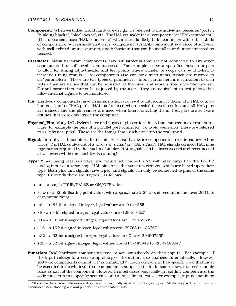
Type: When using real hardware, you would not connect a 24 volt relay output to the +/-10Vanalog input of a servo amp. HAL pins have the same restrictions, which are based upon theirtype. Both pins and signals have types, and signals can only be connected to pins of the sametype. Currently there are 8 types1, as follows:
• BIT - a single TRUE/FALSE or ON/OFF value
• FLOAT - a 32 bit floating point value, with approximately 24 bits of resolution and over 200 bitsof dynamic range.
• U8 - an 8 bit unsigned integer, legal values are 0 to +255
• S8 - an 8 bit signed integer, legal values are -128 to +127
• U16 - a 16 bit unsigned integer, legal values are 0 to +65535
• S16 - a 16 bit signed integer, legal values are -32768 to +32767
• U32 - a 32 bit unsigned integer, legal values are 0 to +4294967295
• S32 - a 32 bit signed integer, legal values are -2147483648 to +2147483647
Function: Real hardware components tend to act immediately on their inputs. For example, ifthe input voltage to a servo amp changes, the output also changes automatically. Howeversoftware components cannot act "automatically". Each component has specific code that mustbe executed to do whatever that component is supposed to do. In some cases, that code simplyruns as part of the component. However in most cases, especially in realtime components, thecode must run in a specific sequence and at specific intervals. For example, inputs should be
1There has been some discussion about whether we really need all the integer types. Maybe they will be reduced oreliminated later. Most signals and pins will be either floats or bits.
CHAPTER 1. INTRODUCTION 12
read before calculations are performed on the input data, and outputs should not be writtenuntil the calculations are done. In these cases, the code is made available to the system inthe form of one or more "functions". Each function is a block of code that performs a specificaction. The system integrator can use "threads" to schedule a series of functions to be executedin a particular order and at specific time intervals.
Thread: A "thread" is a list of functions that runs at specific intervals as part of a realtime task.When a thread is first created, it has a specific time interval (period), but no functions. Func-tions can be added to the thread, and will be executed in order every time the thread runs.
For now a quick example will help get the concept across. We have a parport component namedhal_parport. That component defines one or more HAL pins for each physical pin. The pins aredescribed in that component’s doc section - their names, how each pin relates to the physical pin,are they inverted, can you change polarity, etc. But that alone doesn’t get the data from the HALpins to the physical pins. It takes code to do that, and that is where functions come into thepicture. The parport component needs at least two functions. One to read the physical input pinsand update the HAL pins, the other to take data from the HAL pins and write it to the physicaloutput pins. Both of these functions are part of the parport driver.
1.3 HAL components
Each HAL component is a piece of software with well defined inputs, outputs, and behaviour, thatcan be installed and interconnected as needed. This section lists available components and abrief description of what they do. Complete details for each component are available later in thisdocument.
1.3.1 External Programs with HAL hooks
motion A realtime module that accepts NML motion commands and interacts with HAL
iocontrol A user space module that accepts NML I/O commands and interacts with HAL
classicladder A PLC using HAL for all I/O
halui A user space program that interacts with HAL and sends NML commands (note: right nowexperimental), it is intended to work as a full User Interface using external knobs & switches
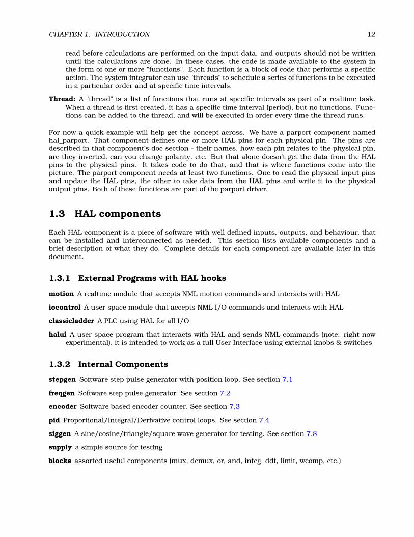
1.3.2 Internal Components
stepgen Software step pulse generator with position loop. See section 7.1
freqgen Software step pulse generator. See section 7.2
encoder Software based encoder counter. See section 7.3
pid Proportional/Integral/Derivative control loops. See section 7.4
siggen A sine/cosine/triangle/square wave generator for testing. See section 7.8
supply a simple source for testing
blocks assorted useful components (mux, demux, or, and, integ, ddt, limit, wcomp, etc.)

CHAPTER 1. INTRODUCTION 13
1.3.3 Hardware Drivers
hal_ax5214h A driver for the Axiom Measurement & Control AX5241H digital I/O board
hal_m5i20 Mesa Electronics 5i20 board
hal_motenc Vital Systems MOTENC-100 board
hal_parport PC parallel port. See section 6.1
hal_ppmc Pico Systems family of controllers (PPMC, USC and UPC)
hal_stg Servo To Go card (version 1 & 2)
hal_vti Vigilant Technologies PCI ENCDAC-4 controller
1.3.4 Tools and Utilities
halcmd Command line tool for configuration and tuning. See section 5.1
halgui GUI tool for configuration and tuning (not implemented yet).
halmeter A handy multimeter for HAL signals. See section 5.3
halscope A full featured digital storage oscilloscope for HAL signals. See section 5.4
Each of these building blocks is described in detail in later chapters.
1.4 Tinkertoys, Erector Sets, Legos and the HAL
A first introduction to HAL concepts can be mind boggling. Building anything with blocks can be achallenge but some of the toys that we played with as kids can be an aid to building things with theHAL.
1.4.1 Tower
I’m watching as my son and his six year old daughter build a tower from a box full ofrandom sized blocks, rods, jar lids and such. The aim is to see how tall they can makethe tower. The narrower the base the more blocks left to stack on top. But the narrowerthe base, the less stable the tower. I see them studying both the next block and the shelfwhere they want to place it to see how it will balance out with the rest of the tower.
The notion of stacking cards to see how tall you can make a tower is a very old and honored wayof spending spare time. At first read, the integrator may have gotten the impression that building aHAL was a bit like that. It can be but with proper planning an integrator can build a stable systemas complex as the machine at hand requires.
1.4.2 Erector Sets2
What was great about the sets was the building blocks, metal struts and angles and plates, all withregularly spaced holes. You could design things and hold them together with the little screws andnuts.
2The Erector Set was an invention of AC Gilbert
CHAPTER 1. INTRODUCTION 14
I got my first erector set for my fourth birthday. I know the box suggested a much olderage than I was. Perhaps my father was really giving himself a present. I had a hard timewith the little screws and nuts. I really needed four arms, one each for the screwdriver,screw, parts to be bolted together, and nut. Perseverence, along with father’s eventualboredom, got me to where I had built every project in the booklet. Soon I was lustingafter the bigger sets that were also printed on that paper. Working with those regularsized pieces opened up a world of construction for me and soon I moved well beyond theillustrated projects.
Hal components are not all the same size and shape but they allow for grouping into larger unitsthat will do useful work.In this sense they are like the parts of an Erector set. Some componentsare long and thin. They essentially connect high level commands to specific physical pins. Othercomponents are more like the rectangular platforms upon which whole machines could be built. Anintegrator will quickly get beyond the brief examples and begin to bolt together components in waysthat are unique to them.
1.4.3 Tinkertoys3
Wooden Tinker toys had a more humane feel that the cold steel of Erector Sets. The heartof construction with Tinker Toys was a round connector with eight holes equally spacedaround the circumference. It also had a hole in the center that was perpendicular to allthe holes around the hub.
Hubs were connected with rods of several different lengths. Builders would make largewheels by using these rods as spokes sticking out from the center hub.
My favorite project was a rotating space station. Short spokes radiated from all the holesin the center hub and connected with hubs on the ends of each spoke. These outer hubswere connected to each other with longer spokes. I’d spend hours dreaming of living insuch a device, walking from hub to hub around the outside as it slowly rotated producingnear gravity in weightless space. Supplies traveled through the spokes in elevators thattransfered them to an from rockets docked at the center hub while they transfered theirprecious cargos.
The idea of one pin or component being the hub for many connections is also an easy conceptwithin the HAL. Examples two and four (see section 2) connect the meter and scope to signals thatare intended to go elsewhere. Less easy is the notion of a hub for several incoming signals but thatis also possible with proper use of functions within that hub component that handle those signalsas they arrive from other components.Another thought that comes forward from this toy is a mechanical representation of HAL threads.A thread might look a bit like a centipede, caterpillar, or earwig. A backbone of hubs, HAL com-ponents, strung together with rods, HAL signals. Each component takes in it own parameters andinput pins and passes on output pins and parameters to the next component. Signals travel alongthe backbone from end to end and are added to or modified by each component in turn.Threads are all about timing and doing a set of tasks from end to end. A mechanical representationis available with Tinkertoys also when we think of the length of the toy as a measure of the timetaken to get from one end to the other. A very different thread or backbone is created by connectingthe same set of hubs with different length rods. The total length of the backbone can be changedby the length of rods used to connect the hubs. The order of operations is the same but the time toget from beginning to end is very diferent.
1.4.4 A Lego Example4
When Lego blocks first arrived in our stores they were pretty much all the same size and shape.Sure there were half sized one and a few quarter sized as well but that rectangular one did most of
3Tinkertoy is now a registered trademark of the Hasbro company.4The Lego name is a trademark of the Lego company.
CHAPTER 1. INTRODUCTION 15
the work. Lego blocks interconnected by snapping the holes in the underside of one onto the pinsthat stuck up on another. By overlapping layers, the joints between could be made very strong,even around corners or tees.
I watched my children and grandchildren build with legos – the same legos. There are afew thousand of them in an old ratty but heavy duty cardboard box that sits in a cornerof the recreation room. It stays there in the open because it was too much trouble to putthe box away and then get it back out for every visit and it is always used during a visit.There must be Lego parts in there from a couple dozen different sets. The little bookletsthat came with them are long gone but the magic of building with interlocking pieces allthe same size is something to watch.
Notice the following description of building a set of motion components in the HAL and how muchlike a wall of lego blocks it is.
The motion module exports a pin for each axis in cartesean space, and another pin foreach axis in joint space. When it is loaded, it automatically creates a "jumper" signal foreach axis, and automatically connects those signals from the joint pin to the carteseanpin. So you automatically have "trivkins" as soon as you load the motion module. (trivkins– trivial kinematics is the case where each motor moves a single axis at 90 degrees to theothers)
The motion module is like a pair of legos in a line end to end. Trivkins is just like a single blockoverlapping the two. The in and out motion pins are plugged into each other by the block restingabove. But the parallel goes on.
If you need some other kinematics, you then load a specific kins component. This com-ponent "knows" the names of the pins that the motion module uses for each axis, bothjoint and cartesean. When the module loads, it again automatically creates signals andconnects its own pins to the motion module’s pins (which will disconnect the "jumpers").It could also know the thread names used by the motion module, and could automaticallyadd it’s own functions to those threads.
Trivkins is removed so that the motion blocks can be spread apart and by using other blocks, adifferent bridge is built between input and output pins. In Lego terms, trivkins might be a grayblock and xxkins might be a yellow block.
So the net result is that 24 HAL signals and two HAL functions are configured, with noaction needed by the integrator other than loading the module. (24 signals are from 6axis * 2 because we have joint and cartesean * 2 because we have forward and inversekinematics. Two functions because we have forward and inverse.) Because these HALsignals exist, they can be metered or scoped or whatever for testing. But because bothmodules know their names and know how to automatically connect them, the integratordoesn’t have to know or care.
This kind of automatic HAL configuration is possible because all kinematics modules "plug in" thesame way.
1.5 Timing Issues In HAL
Threads is going to take a major intellectual push because unlike the physical wiring models be-tween black boxes that we have said that HAL is based upon, simply connecting two pins with ahal-signal falls far short of the action of the physical case.True relay logic consists of relays connected together, and when a contact opens or closes, currentflows (or stops) immediately. Other coils may change state, etc, and it all just "happens". But in

CHAPTER 1. INTRODUCTION 16
PLC style ladder logic, it doesn’t work that way. Usually in a single pass through the ladder, eachrung is evaluated in the order in which it appears, and only once per pass. A perfect example is asingle rung ladder, with a NC contact in series with a coil. The contact and coil belong to the samerelay.
If this were a conventional relay, as soon as the coil is energized, the contacts begin to open andde-energize it. That means the contacts close again, etc, etc. The relay becomes a buzzer.
With a PLC, if the coil is OFF and the contact is closed when the PLC begins to evaluate the rung,then when it finishes that pass, the coil is ON. The fact that turning on the coil opens the contactfeeding it is ignored until the next pass. On the next pass, the PLC sees that the contact is open, andde-energizes the coil. So the relay still switches rapidly between on and off, but at a rate determinedby how often the PLC evaluates the rung.
In HAL, the function is the code that evaluates the rung(s). In fact a HAL-aware realtime versionof ClassicLadder would export a function to do exactly that. Meanwhile, a thread is the thing thatruns the function at specific time intervals. Just like you can choose to have a PLC evaluate all itsrungs every 10mS, or every second, you can define HAL threads with different periods.
What distinguishes one thread from another is _not_ what the thread does - that is determined bywhich functions are connected to it. The real distinction is simply how often a thread runs.
In EMC we might have a 15uS thread, a 1mS thread, and a 10mS thread. These would be createdbased on "Period", "ServoPeriod", and "TrajPeriod" respectively - the actual times would depend onthe ini. That is one part of the config process, and although it could be done manually, it wouldnormally be automatic.
The next step is to decide what each thread needs to do. Some of those decisions would also beautomatic - the motion module would automatically connect its "PlanTrajectory" function to theTrajPeriod thread, and its "ControlMotion" function to the ServoPeriod thread.
Other connections would be made by the integrator (at least the first time). These might includehooking the STG driver’s encoder read and DAC write functions to the servo thread, or hookingstepgen’s function to the fast thread, along with the parport function(s) to write the steps to theport.
1.6 Dynamic Linking and Configuration
It is indeed possible to configure HAL with a form of dynamic linking. But it is different than DLLsas used by Microsoft(tm) or shared libraries as used in Linux. Both DLLs and shared librariesessentially say "Here I am, I have this code you might want to use", where "you" is other modules.Then when those other modules or programs are loaded, they say "I need a function called ’X’, isthere one?" and if the answer is YES, they link to it.
With HAL, a component still says "Here I am, I have this code you might want to use", but "you"is the system integrator. The integrator gets to decide what functions are used and doesn’t have toworry about another module needing "function X" and not finding it.
HAL can follow the normal DLL model as well. Although most components will simply export pins,functions, and parameters, and then wait for the integrator (or a saved file) to interconnect them, wecan write modules that (attempt to) make connections when they are installed. One specific placewhere this would work well is kinematics as illustrated in the Lego section 1.4.4 .
Chapter 2
HAL Tutorial
2.1 Before we start
Configuration moves from theory to device – HAL device that is. For those who have had just a bit ofcomputer programming, this section is the “Hello World” of the HAL. As noted above halcmd can beused to create a working system. It is a command line or text file tool for configuration and tuning.The following examples illustrate its setup and operation.
2.1.1 Notation
Command line examples are presented in bold typewriter font. Responses from the computerwill be in typewriter font. Text inside square brackets [like-this] is optional. Text insideangle brackets <like-this> represents a field that can take on different values, and the adjacentparagraph will explain the appropriate values. Text items separated by a vertical bar means thatone or the other, but not both, should be present. All command line examples assume that you arein the emc2/ directory, and paths will be shown accordingly when needed.
2.1.2 Root Privilges
In the beginning days of HAL there was quite often the need to run things with root privileges.Most of those things were related to the fact that HAL uses kernel modules to do much of it’s work,and because it also can access hardware directly. Knowing that it is usually safer to avoid doingday-to-day work as root, most of those things were reworked so that very limited root privileges arerequired. If you are running a version of EMC2 and HAL more recent than early 2006, you canpretty much ignore this section.To get around the need for root, emc2 uses a small program called emc_module_helper, whichduring the build process gets setuid status (thus has root privileges). This small software moduletakes care of the insmod/rmmod commands that are needed to insert/delete modules from theHAL. You can use this program directly, but it’s lots easier to use the halcmd loadrt & unloadrtcommands 5.1Here is an example of what happens when you don’t have root privileges:
emc2$ bin/hal_parport 0278PARPORT: ERROR: could not get I/O permissionemc2$
As an alternative to logging in as root, you can use the sudo command or the su -c command.The sudo command is very convenient to use, and does not require you to know the root password.However, it needs to be configured by someone who does know the root password. The configurationdetermines who may use sudo, and what commands they can use it for. We will not discuss sudo
17
CHAPTER 2. HAL TUTORIAL 18
configuration here, try man sudo and/or talk to your system administrator. If sudo is properlyconfigured, here is what happens:
emc2$ sudo bin/hal_parport 0278Password: <enter your password>PARPORT: installed driver for 1 portsemc2$
As an added convenience, sudo remembers your password for a short time, so if you enter anothersudo command within the time limit (usually 5 minutes) you don’t have to type your passwordagain.The su -c command does not require configuration, but does require you to know the root pass-word, and to type it in for every command. You also must put quotes around the command you aretrying to run:
emc2$ su -c "bin/hal_parport 0278"Password: <enter root password>PARPORT: installed driver for 1 portsemc2$
To avoid cluttering up the examples, we will not show sudo or su -c. Instead, commands thatrequire root privileges will be preceded by #, and other commands will be preceded by by $.
emc2$ ls binemc2# bin/hal_parport 0278
2.1.3 The RTAPI environment
RTAPI stands for Real Time Application Programming Interface. Many HAL components work inrealtime, and all HAL components store data in shared memory so realtime components can ac-cess it. Normal Linux does not support realtime programming or the type of shared memory thatHAL needs. Fortunately there are realtime operating systems (RTOS’s) that provide the neccessaryextensions to Linux. Unfortunately, each RTOS does things a little differently.To address these differences, the EMC team came up with RTAPI, which provides a consistent wayfor programs to talk to the RTOS. If you are a programmer who wants to work on the internals ofEMC, you may want to study emc2/src/rtapi/rtapi.h to understand the API. But if you are anormal person all you need to know about RTAPI is that it (and the RTOS) needs to be loaded intothe memory of your computer before you do anything with HAL.For this tutorial, we are going to assume that you have successfully compiled the emc2/ sourcetree. In that case, all you need to do is load the required RTOS and RTAPI modules into memory.Just run the following command (needs root privileges):
emc2# scripts/realtime start
With the realtime OS and RTAPI loaded, we can move into the first example.
2.2 A Simple Example
2.2.1 Loading a realtime component
For the first example, we will use a HAL component called siggen, which is a simple signal genera-tor. A complete description of the siggen component can be found in section 7.8 of this document.It is a realtime component, implemented as a Linux kernel module and located in the directoryemc2/rtlib/. To load siggen use the halcmd loadrt command:
emc2$ bin/halcmd loadrt siggenemc2$

CHAPTER 2. HAL TUTORIAL 19
2.2.2 Examining the HAL
Now that the module is loaded, it is time to introduce halcmd, the command line tool used to config-ure the HAL. This tutorial will introduce some halcmd features, for a more complete description tryman halcmd, or see the halcmd reference in section 5.1 of this document. The first halcmd featureis the show command. This command displays information about the current state of the HAL. Toshow all installed components:
emc2$ bin/halcmd show compLoaded HAL Components:ID Type Name02 User halcmd2134501 RT siggenemc2$
Since halcmd itself is a HAL component, it will always show up in the list1. The list also showsthe siggen component that we installed in the previous step. The “RT” under “Type” indicates thatsiggen is a realtime component.Next, let’s see what pins siggen makes available:
emc2$ bin/halcmd show pinComponent Pins:Owner Type Dir Value Name02 float -W 0.00000e+00 siggen.0.cosine02 float -W 0.00000e+00 siggen.0.sawtooth02 float -W 0.00000e+00 siggen.0.sine02 float -W 0.00000e+00 siggen.0.square02 float -W 0.00000e+00 siggen.0.triangle
emc2$
This command displays all of the pins in the HAL - a complex system could have dozens or hundredsof pins. But right now there are only five pins. All five of these pins are floating point, and all fivecarry data out of the siggen component. Since we have not yet executed the code contained withinthe component, all the pins have a value of zero.The next step is to look at parameters:
emc2$ bin/halcmd show paramParameters:Owner Type Dir Value Name02 float -W 1.00000e+00 siggen.0.amplitude02 float -W 1.00000e+00 siggen.0.frequency02 float -W 0.00000e+00 siggen.0.offset02 s32 R- 0 siggen.0.update.time02 s32 RW 0 siggen.0.update.tmax
emc2$
The show param command shows all the parameters in the HAL. Right now each parameter hasthe default value it was given when the component was loaded. Note the column labeled Dir. Theparameters labeled -W are writeable ones that are never changed by the component itself, insteadthey are meant to be changed by the user to control the component. We will see how to do this later.Parameters labeled R- are read only parameters. They can be changed only by the component.Finally, parameter labeled RW are read-write parameters. That means that thay are changed by thecomponent, but can also be changed by the user. Note: the parameters siggen.0.update.timeand siggen.0.update.tmax are for debugging purposes, and won’t be covered in this section.Most realtime components export one or more functions to actually run the realtime code theycontain. Let’s see what function(s) siggen exported:
1The number after halcmd in the component list is the process ID. It is possible to run more than one copy of halcmd atthe same time (in different windows for example), so the PID is added to the end of the name to make it unique.

CHAPTER 2. HAL TUTORIAL 20
emc2$ bin/halcmd show functExported Functions:Owner CodeAddr Arg FP Users Name02 C48E31C4 C48D2054 YES 0 siggen.0.update
emc2$
The siggen component exported a single function. It requires floating point. It is not currently linkedto any threads, so “users” is zero2.
2.2.3 Making realtime code run
To actually run the code contained in the function siggen.0.update, we need a realtime thread.Eventually halcmd will have a newthread command that can be used to create a thread, but thatrequires some significant internal changes. For now, we have a component called threads thatis used to create a new thread. Lets create a thread called test-thread with a period of 1mS(1000000nS):
emc2$ bin/halcmd loadrt threads name1=test-thread period1=1000000
Let’s see if that worked:
emc2$ bin/halcmd show threadRealtime Threads:
Period FP Name (Time, Max-Time)999849 YES test-thread ( 0, 0 )
emc2$
It did. The period is not exactly 1000000nS because of hardware limitations, but we have a threadthat runs at approximately the correct rate, and which can handle floating point functions. Thenext step is to connect the function to the thread:
emc2$ bin/halcmd addf siggen.0.update test-threademc2$
Up till now, we’ve been using halcmd only to look at the HAL. However, this time we used theaddf (add function) command to actually change something in the HAL. We told halcmd to add thefunction siggen.0.update to the thread test-thread, and if we look at the thread list again, wesee that it succeeded:
emc2$ bin/halcmd show threadRealtime Threads:
Period FP Name (Time, Max-Time)999849 YES test-thread ( 0, 0 )
1 siggen.0.updateemc2$
There is one more step needed before the siggen component starts generating signals. When theHAL is first started, the thread(s) are not actually running. This is to allow you to completelyconfigure the system before the realtime code starts. Once you are happy with the configuration,you can start the realtime code like this:
emc2$ bin/halcmd startemc2$
Now the signal generator is running. Let’s look at it’s output pins:
2The codeaddr and arg fields were used in development, and should probably be removed from the halcmd listing.

CHAPTER 2. HAL TUTORIAL 21
emc2$ bin/halcmd show pinComponent Pins:Owner Type Dir Value Name02 float -W 5.61498e-01 siggen.0.cosine02 float -W -6.89775e-01 siggen.0.sawtooth02 float -W 8.27478e-01 siggen.0.sine02 float -W -1.00000e+00 siggen.0.square02 float -W 3.79549e-01 siggen.0.triangle
emc2$ bin/halcmd show pinComponent Pins:Owner Type Dir Value Name02 float -W 9.23063e-01 siggen.0.cosine02 float -W -8.74322e-01 siggen.0.sawtooth02 float -W 3.84649e-01 siggen.0.sine02 float -W -1.00000e+00 siggen.0.square02 float -W 7.48645e-01 siggen.0.triangle
emc2$
We did two show pin commands in quick succession, and you can see that the outputs are nolonger zero. The sine, cosine, sawtooth, and triangle outputs are changing constantly. The squareoutput is also working, however it simply switches from +1.0 to -1.0 every cycle, and it happened tobe at -1.0 for both commands.
2.2.4 Changing parameters
The real power of HAL is that you can change things. For example, we can use the setp commandto set the value of a parameter. Let’s change the amplitude of the signal generator from 1.0 to 5.0:
emc2$ bin/halcmd setp siggen.0.amplitude 5emc2$
Check the parameters and pins again:
emc2$ bin/halcmd show paramParameters:Owner Type Dir Value Name02 float -W 5.00000e+00 siggen.0.amplitude02 float -W 1.00000e+00 siggen.0.frequency02 float -W 0.00000e+00 siggen.0.offset
emc2$ bin/halcmd show pinComponent Pins:Owner Type Dir Value Name02 float -W -1.66602e+00 siggen.0.cosine02 float -W 1.95935e+00 siggen.0.sawtooth02 float -W -4.71428e+00 siggen.0.sine02 float -W 5.00000e+00 siggen.0.square02 float -W -1.08130e+00 siggen.0.triangle
emc2$ bin/halcmd show pinComponent Pins:Owner Type Dir Value Name02 float -W -3.82623e+00 siggen.0.cosine02 float -W -1.11309e+00 siggen.0.sawtooth02 float -W 3.21869e+00 siggen.0.sine02 float -W -5.00000e+00 siggen.0.square02 float -W -2.77382e+00 siggen.0.triangle
emc2$
CHAPTER 2. HAL TUTORIAL 22
Note that the value of parameter siggen.0.amplitude has changed to 5.000, and that the pinsnow have larger values. The square wave output now switches from +5.0 to -5.0, and we happenedto catch it switching this time.
2.2.5 Saving the HAL configuration
Most of what we have done with halcmd so far has simply been viewing things with the showcommand. However two of the commands actually changed things. As we design more complexsystems with HAL, we will use many commands to configure things just the way we want them.HAL has the memory of an elephant, and will retain that configuration until we shut it down. Butwhat about next time? We don’t want to manually enter a bunch of commands every time we wantto use the system. We can save the configuration of the entire HAL with a single command:
emc2$ bin/halcmd save# componentsloadrt threads name1=test-thread period1=1000000loadrt siggen# signals# links# parameter valuessetp siggen.0.amplitude 5.00000e+00setp siggen.0.frequency 1.00000e+00setp siggen.0.offset 0.00000e+00# realtime thread/function linksaddf siggen.0.update test-threademc2$
The output of the save command is a sequence of HAL commands. If you start with an “empty” HALand run all these commands, you will get the configuration that existed when the save commandwas issued. To save these commands for later use, we simply redirect the output to a file:
emc2$ bin/halcmd save >saved.halemc2$
2.2.6 Restoring the HAL configuration
To restore the HAL configuration stored in saved.hal, we need to execute all of those HAL com-mands. To do that, we use halcmd -f <filename> which reads commands from a file:
emc2$ bin/halcmd -f saved.halemc2$
2.3 Looking at the HAL with halmeter
You can build very complex HAL systems without ever using a graphical interface. However thereis something satisfying about seeing the result of your work. The first and simplest GUI tool forthe HAL is halmeter. It is a very simple program that is the HAL equivalent of the handy Flukemultimeter (or Simpson analog meter for the old timers).We will use the siggen component again to check out halmeter. If you just finished the previousexample, then siggen is already loaded. If not, we can load it just like we did before:
emc2$ scripts/realtime startemc2$ loadrt siggenemc2$ loadrt threads name1=test-thread period1=1000000
CHAPTER 2. HAL TUTORIAL 23
emc2$ bin/halcmd addf siggen.0.update test-threademc2$ bin/halcmd startemc2$ bin/halcmd setp siggen.0.amplitude 5emc2$
2.3.1 Starting halmeter
At this point we have the siggen component loaded and running. It’s time to start halmeter. Sincehalmeter is a GUI app, X must be running. We can start halmeter in the background by followingit’s name with a ’&’:
emc2$ bin/halmeter &[1] 22093emc2$
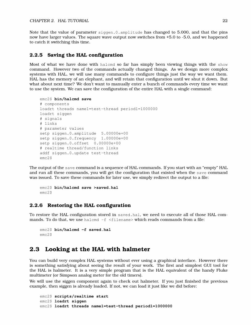
Since we started halmeter in the background, Linux prints its process id [1] 22093 and immedi-ately returns to the shell prompt. At the same time, a halcmd window opens on your screen, lookingsomething like figure 2.1. Note that you don’t have to run halmeter in the background. If you omit’&’, it will start and behave exactly the same, but you won’t get your shell prompt back until you exitfrom halmeter.
Figure 2.1: Halmeter at startup, nothing selected
2.3.2 Using halmeter
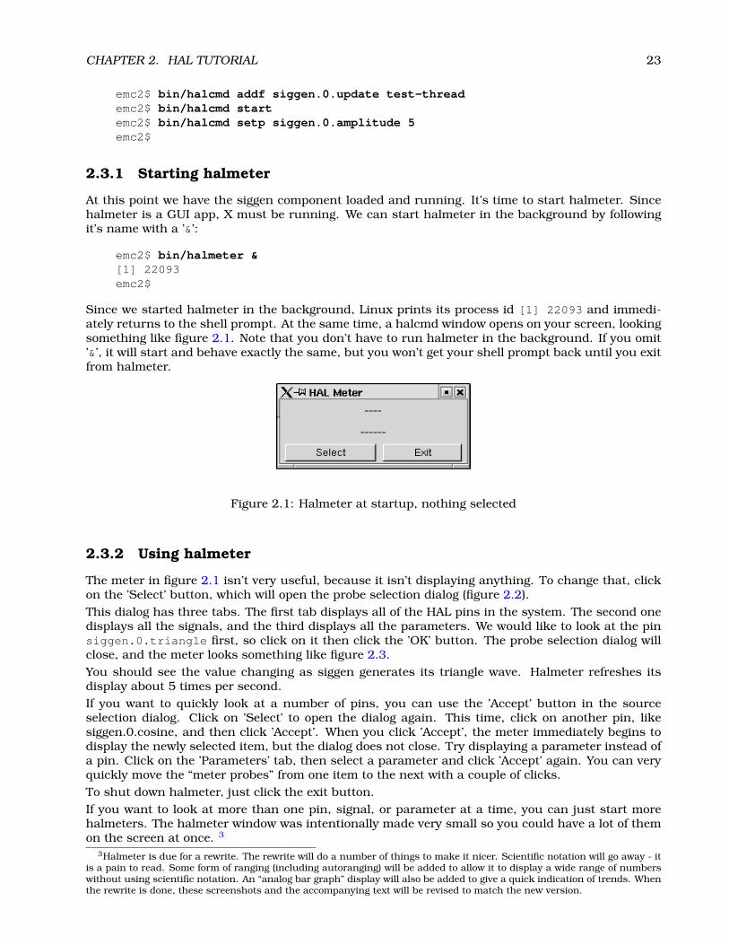
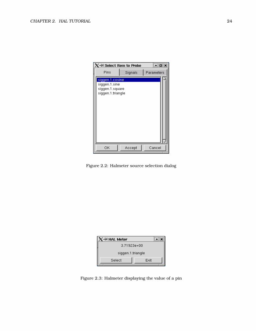
The meter in figure 2.1 isn’t very useful, because it isn’t displaying anything. To change that, clickon the ’Select’ button, which will open the probe selection dialog (figure 2.2).This dialog has three tabs. The first tab displays all of the HAL pins in the system. The second onedisplays all the signals, and the third displays all the parameters. We would like to look at the pinsiggen.0.triangle first, so click on it then click the ’OK’ button. The probe selection dialog willclose, and the meter looks something like figure 2.3.You should see the value changing as siggen generates its triangle wave. Halmeter refreshes itsdisplay about 5 times per second.If you want to quickly look at a number of pins, you can use the ’Accept’ button in the sourceselection dialog. Click on ’Select’ to open the dialog again. This time, click on another pin, likesiggen.0.cosine, and then click ’Accept’. When you click ’Accept’, the meter immediately begins todisplay the newly selected item, but the dialog does not close. Try displaying a parameter instead ofa pin. Click on the ’Parameters’ tab, then select a parameter and click ’Accept’ again. You can veryquickly move the “meter probes” from one item to the next with a couple of clicks.To shut down halmeter, just click the exit button.If you want to look at more than one pin, signal, or parameter at a time, you can just start morehalmeters. The halmeter window was intentionally made very small so you could have a lot of themon the screen at once. 3
3Halmeter is due for a rewrite. The rewrite will do a number of things to make it nicer. Scientific notation will go away - itis a pain to read. Some form of ranging (including autoranging) will be added to allow it to display a wide range of numberswithout using scientific notation. An “analog bar graph” display will also be added to give a quick indication of trends. Whenthe rewrite is done, these screenshots and the accompanying text will be revised to match the new version.
CHAPTER 2. HAL TUTORIAL 24
Figure 2.2: Halmeter source selection dialog
Figure 2.3: Halmeter displaying the value of a pin
CHAPTER 2. HAL TUTORIAL 25
2.4 A slightly more complex example.
Up till now we have only loaded one HAL component. But the whole idea behind the HAL is to allowyou to load and connect a number of simple components to make up a complex system. The nextexample will use two components.Before we can begin building this new example, we want to start with a clean slate. If you justfinished one of the previous examples, we need to remove the all components and reload the RTAPIand HAL libraries:
emc2$ bin/halcmd unloadrt allemc2$ scripts/realtime restartemc2$
2.4.1 Installing the components
Now we are going to load the step pulse generator component. For a detailed description of thiscomponent refer to section 7.2. For now, we can skip the details, and just run the following com-mands:4
emc2$ bin/halcmd loadrt freqgen step_type=0,0emc2$ bin/halcmd loadrt siggenemc2$ bin/halcmd loadrt threads name1=fast fp1=0 period1=50000 \name2=slow period2=1000000emc2$
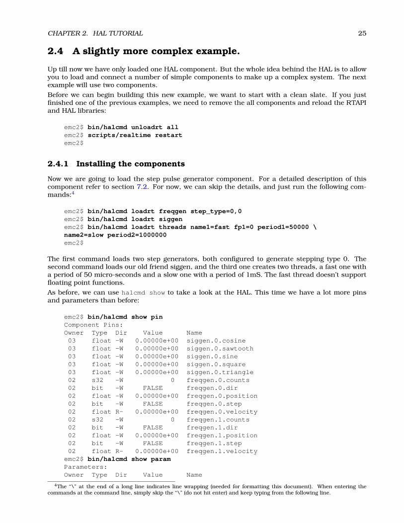
The first command loads two step generators, both configured to generate stepping type 0. Thesecond command loads our old friend siggen, and the third one creates two threads, a fast one witha period of 50 micro-seconds and a slow one with a period of 1mS. The fast thread doesn’t supportfloating point functions.As before, we can use halcmd show to take a look at the HAL. This time we have a lot more pinsand parameters than before:
emc2$ bin/halcmd show pinComponent Pins:Owner Type Dir Value Name03 float -W 0.00000e+00 siggen.0.cosine03 float -W 0.00000e+00 siggen.0.sawtooth03 float -W 0.00000e+00 siggen.0.sine03 float -W 0.00000e+00 siggen.0.square03 float -W 0.00000e+00 siggen.0.triangle02 s32 -W 0 freqgen.0.counts02 bit -W FALSE freqgen.0.dir02 float -W 0.00000e+00 freqgen.0.position02 bit -W FALSE freqgen.0.step02 float R- 0.00000e+00 freqgen.0.velocity02 s32 -W 0 freqgen.1.counts02 bit -W FALSE freqgen.1.dir02 float -W 0.00000e+00 freqgen.1.position02 bit -W FALSE freqgen.1.step02 float R- 0.00000e+00 freqgen.1.velocity
emc2$ bin/halcmd show paramParameters:Owner Type Dir Value Name
4The “\” at the end of a long line indicates line wrapping (needed for formatting this document). When entering thecommands at the command line, simply skip the “\” (do not hit enter) and keep typing from the following line.

CHAPTER 2. HAL TUTORIAL 26
03 float -W 1.00000e+00 siggen.0.amplitude03 float -W 1.00000e+00 siggen.0.frequency03 float -W 0.00000e+00 siggen.0.offset02 u8 -W 1 (01) freqgen.0.dirhold02 u8 -W 1 (01) freqgen.0.dirsetup02 float R- 0.00000e+00 freqgen.0.frequency02 float -W 0.00000e+00 freqgen.0.maxaccel02 float -W 1.00000e+15 freqgen.0.maxfreq02 float -W 1.00000e+00 freqgen.0.position-scale02 s32 R- 0 freqgen.0.rawcounts02 u8 -W 1 (01) freqgen.0.steplen02 u8 -W 1 (01) freqgen.0.stepspace02 float -W 1.00000e+00 freqgen.0.velocity-scale02 u8 -W 1 (01) freqgen.1.dirhold02 u8 -W 1 (01) freqgen.1.dirsetup02 float R- 0.00000e+00 freqgen.1.frequency02 float -W 0.00000e+00 freqgen.1.maxaccel02 float -W 1.00000e+15 freqgen.1.maxfreq02 float -W 1.00000e+00 freqgen.1.position-scale02 s32 R- 0 freqgen.1.rawcounts02 u8 -W 1 (01) freqgen.1.steplen02 u8 -W 1 (01) freqgen.1.stepspace02 float -W 1.00000e+00 freqgen.1.velocity-scale
emc2$
2.4.2 Connecting pins with signals
What we have is two step pulse generators, and a signal generator. Now it is time to create some HALsignals to connect the two components. We are going to pretend that the two step pulse generatorsare driving the X and Y axis of a machine. We want to move the table in circles. To do this, we willsend a cosine signal to the X axis, and a sine signal to the Y axis. The siggen module creates thesine and cosine, but we need “wires” to connect the modules together. In the HAL, “wires” are calledsignals. We need to create two of them. We can call them anything we want, for this example theywill be X_vel and Y_vel. To create them we use the the newsig command. We also need to specifythe type of data that will flow through these “wires”, in this case it is floating point:
emc2$ bin/halcmd newsig X_vel floatemc2$ bin/halcmd newsig Y_vel floatemc2$
To make sure that worked, we can look at all the signals:
emc2$ bin/halcmd show sigSignals:Type Value Namefloat 0.00000e+00 X_velfloat 0.00000e+00 Y_velemc2$
The next step is to connect the signals to component pins. The signal X_vel is intended to run fromthe cosine output of the signal generator to the velocity input of the first step pulse generator. Thefirst step is to connect the signal to the signal generator output. To connect a signal to a pin we usethe linksp command.
emc2$ bin/halcmd linksp X_vel siggen.0.cosineemc2$
CHAPTER 2. HAL TUTORIAL 27
To see the effect of the linksp command, we show the signals again:
emc2$ bin/halcmd show sigSignals:Type Value Namefloat 0.00000e+00 X_vel
<== siggen.0.cosinefloat 0.00000e+00 Y_velemc2$
When a signal is connected to one or more pins, the show command lists the pins immediatelyfollowing the signal name. The “arrow” shows the direction of data flow - in this case, data flowsfrom pin siggen.0.cosine to signal X_vel. Now let’s connect the X_vel to the velocity input of astep pulse generator:
emc2$ bin/halcmd linksp X_vel freqgen.0.velocityemc2$
We can also connect up the Y axis signal Y_vel. It is intended to run from the sine output of thesignal generator to the input of the second step pulse generator:
emc2$ bin/halcmd linksp Y_vel siggen.0.sineemc2$ bin/halcmd linksp Y_vel freqgen.1.velocityemc2$
Now let’s take a final look at the signals and the pins connected to them:
emc2$ bin/halcmd show sigSignals:Type Value Namefloat 0.00000e+00 X_vel
<== siggen.0.cosine==> freqgen.0.velocity
float 0.00000e+00 Y_vel<== siggen.0.sine==> freqgen.1.velocity
emc2$
The show sig command makes it clear exactly how data flows through the HAL. For example, theX_vel signal comes from pin siggen.0.cosine, and goes to pin freqgen.0.velocity.
2.4.3 Setting up realtime execution - threads and functions
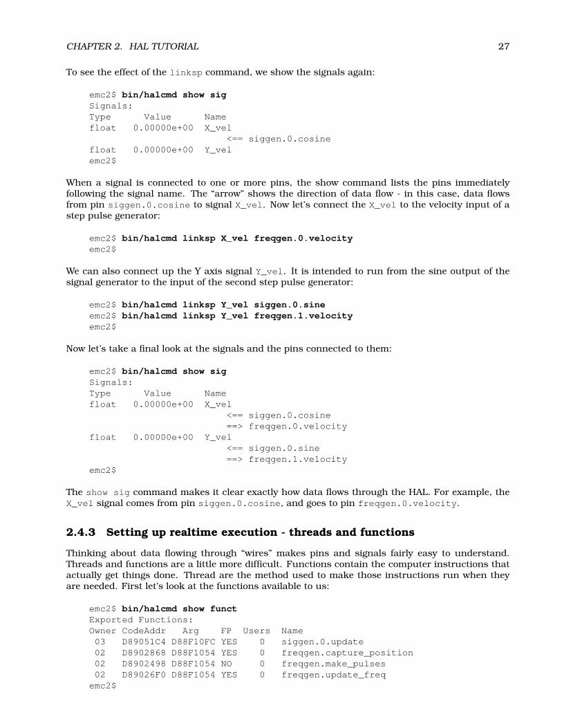
Thinking about data flowing through “wires” makes pins and signals fairly easy to understand.Threads and functions are a little more difficult. Functions contain the computer instructions thatactually get things done. Thread are the method used to make those instructions run when theyare needed. First let’s look at the functions available to us:
emc2$ bin/halcmd show functExported Functions:Owner CodeAddr Arg FP Users Name03 D89051C4 D88F10FC YES 0 siggen.0.update02 D8902868 D88F1054 YES 0 freqgen.capture_position02 D8902498 D88F1054 NO 0 freqgen.make_pulses02 D89026F0 D88F1054 YES 0 freqgen.update_freq
emc2$
CHAPTER 2. HAL TUTORIAL 28
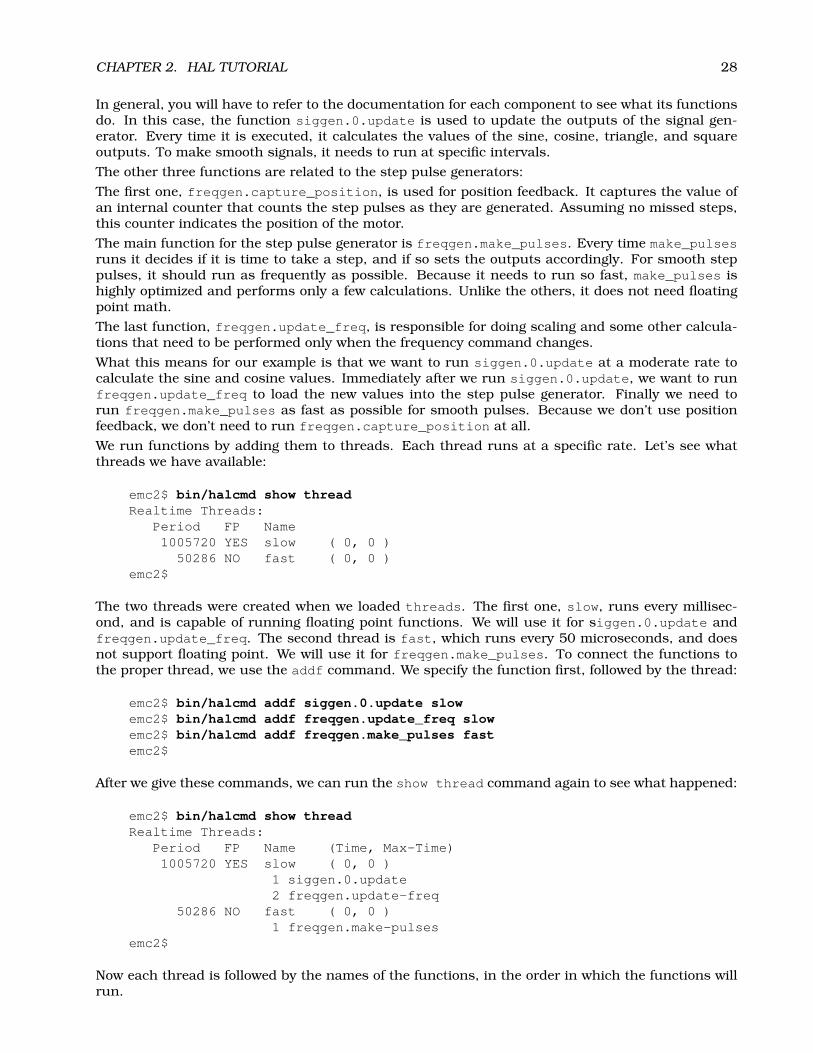
In general, you will have to refer to the documentation for each component to see what its functionsdo. In this case, the function siggen.0.update is used to update the outputs of the signal gen-erator. Every time it is executed, it calculates the values of the sine, cosine, triangle, and squareoutputs. To make smooth signals, it needs to run at specific intervals.The other three functions are related to the step pulse generators:The first one, freqgen.capture_position, is used for position feedback. It captures the value ofan internal counter that counts the step pulses as they are generated. Assuming no missed steps,this counter indicates the position of the motor.The main function for the step pulse generator is freqgen.make_pulses. Every time make_pulsesruns it decides if it is time to take a step, and if so sets the outputs accordingly. For smooth steppulses, it should run as frequently as possible. Because it needs to run so fast, make_pulses ishighly optimized and performs only a few calculations. Unlike the others, it does not need floatingpoint math.The last function, freqgen.update_freq, is responsible for doing scaling and some other calcula-tions that need to be performed only when the frequency command changes.What this means for our example is that we want to run siggen.0.update at a moderate rate tocalculate the sine and cosine values. Immediately after we run siggen.0.update, we want to runfreqgen.update_freq to load the new values into the step pulse generator. Finally we need torun freqgen.make_pulses as fast as possible for smooth pulses. Because we don’t use positionfeedback, we don’t need to run freqgen.capture_position at all.We run functions by adding them to threads. Each thread runs at a specific rate. Let’s see whatthreads we have available:
emc2$ bin/halcmd show threadRealtime Threads:
Period FP Name1005720 YES slow ( 0, 0 )
50286 NO fast ( 0, 0 )emc2$
The two threads were created when we loaded threads. The first one, slow, runs every millisec-ond, and is capable of running floating point functions. We will use it for siggen.0.update andfreqgen.update_freq. The second thread is fast, which runs every 50 microseconds, and doesnot support floating point. We will use it for freqgen.make_pulses. To connect the functions tothe proper thread, we use the addf command. We specify the function first, followed by the thread:
emc2$ bin/halcmd addf siggen.0.update slowemc2$ bin/halcmd addf freqgen.update_freq slowemc2$ bin/halcmd addf freqgen.make_pulses fastemc2$
After we give these commands, we can run the show thread command again to see what happened:
emc2$ bin/halcmd show threadRealtime Threads:
Period FP Name (Time, Max-Time)1005720 YES slow ( 0, 0 )
1 siggen.0.update2 freqgen.update-freq
50286 NO fast ( 0, 0 )1 freqgen.make-pulses
emc2$
Now each thread is followed by the names of the functions, in the order in which the functions willrun.

CHAPTER 2. HAL TUTORIAL 29
2.4.4 Setting parameters
We are almost ready to start our HAL system. However we still need to adjust a few parameters. Bydefault, the siggen component generates signals that swing from +1 to -1. For our example that isfine, we want the table speed to vary from +1 to -1 inches per second. However the scaling of the steppulse generator isn’t quite right. By default, it generates an output frequency of 1 step per secondwith an input of 1.000. It is unlikely that one step per second will give us one inch per second oftable movement. Let’s assume instead that we have a 5 turn per inch leadscrew, connected to a 200step per rev stepper with 10x microstepping. So it takes 2000 steps for one revolution of the screw,and 5 revolutions to travel one inch. that means the overall scaling is 10000 steps per inch. Weneed to multiply the velocity input to the step pulse generator by 10000 to get the proper output.That is exactly what the parameter freqgen.n.velocity-scale is for. In this case, both the X andY axis have the same scaling, so we set the scaling parameters for both to 10000:
emc2$ bin/halcmd setp freqgen.0.velocity-scale 10000emc2$ bin/halcmd setp freqgen.1.velocity-scale 10000emc2$
This velocity scaling means that when the pin freqgen.0.velocity is 1.000, the step generatorwill generate 10000 pulses per second (10KHz). With the motor and leadscrew described above, thatwill result in the axis moving at exactly 1.000 inches per second. This illustrates a key HAL concept- things like scaling are done at the lowest possible level, in this case in the step pulse generator.The internal signal X_vel is the velocity of the table in inches per second, and other componentssuch as siggen don’t know (or care) about the scaling at all. If we changed the leadscrew, or motor,we would change only the scaling parameter of the step pulse generator.
2.4.5 Run it!
We now have everything configured and are ready to start it up. Just like in the first example, weuse the start command:
emc2$ bin/halcmd startemc2$
Although nothing appears to happen, inside the computer the step pulse generator is cranking outstep pulses, varying from 10KHz forward to 10KHz reverse and back again every second. Later inthis tutorial we’ll see how to bring those internal signals out to run motors in the real world, butfirst we want to look at them and see what is happening.
2.5 Taking a closer look with halscope.
The previous example generates some very interesting signals. But much of what happens is fartoo fast to see with halmeter. To take a closer look at what is going on inside the HAL, we want anoscilloscope. Fortunately HAL has one, called halscope.
2.5.1 Starting Halscope
Halscope has two parts - a realtime part that is loaded as a kernel module, and a user part thatsupplies the GUI and display. Before starting the GUI you must load the realtime part:
emc2$ bin/halcmd loadrt scope_rtemc2$
Once the realtime part is loaded, we can start the GUI. Like halmeter, you can follow it with & so itruns in the background and you get your shell prompt back immediately:
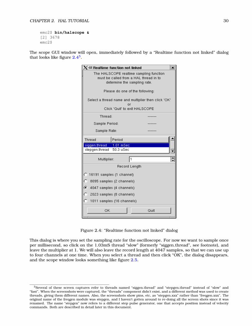
CHAPTER 2. HAL TUTORIAL 30
emc2$ bin/halscope &[2] 3678emc2$
The scope GUI window will open, immediately followed by a “Realtime function not linked” dialogthat looks like figure 2.45.
Figure 2.4: “Realtime function not linked” dialog
This dialog is where you set the sampling rate for the oscilloscope. For now we want to sample onceper millisecond, so click on the 1.03mS thread “slow” (formerly “siggen.thread”, see footnote), andleave the multiplier at 1. We will also leave the record length at 4047 samples, so that we can use upto four channels at one time. When you select a thread and then click “OK”, the dialog disappears,and the scope window looks something like figure 2.5.
5Several of these screen captures refer to threads named “siggen.thread” and “stepgen.thread” instead of “slow” and“fast”. When the screenshots were captured, the “threads” component didn’t exist, and a different method was used to createthreads, giving them different names. Also, the screenshots show pins, etc, as “stepgen.xxx” rather than “freqgen.xxx”. Theoriginal name of the freqgen module was stepgen, and I haven’t gotten around to re-doing all the screen shots since it wasrenamed. The name “stepgen” now refers to a different step pulse generator, one that accepts position instead of velocitycommands. Both are described in detail later in this document.
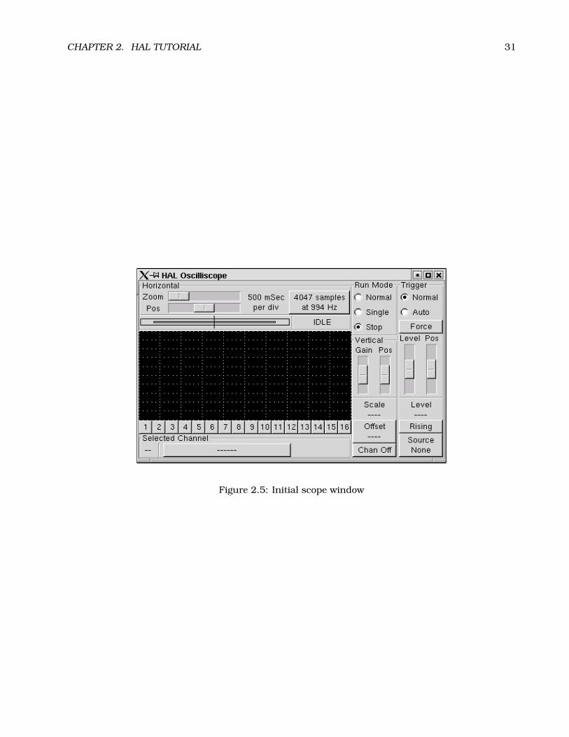
CHAPTER 2. HAL TUTORIAL 31
Figure 2.5: Initial scope window

CHAPTER 2. HAL TUTORIAL 32
2.5.2 Hooking up the “scope probes”
At this point, Halscope is ready to use. We have already selected a sample rate and record length,so the next step is to decide what to look at. This is equivalent to hooking “virtual scope probes” tothe HAL. Halscope has 16 channels, but the number you can use at any one time depends on therecord length - more channels means shorter records, since the memory available for the record isfixed at approximately 16,000 samples.
The channel buttons run across the bottom of the halscope screen. Click button “1”, and you willsee the “Select Channel Source” dialog, figure 2.6. This dialog is very similar to the one used byHalmeter. We would like to look at the signals we defined earlier, so we click on the “Signals” tab,and the dialog displays all of the signals in the HAL (only two for this example).
Figure 2.6: Select Channel Source dialog
To choose a signal, just click on it. In this case, we want to use channel 1 to display the signal“X_vel”. When we click on “X_vel”, the dialog closes and the channel is now selected. The channel 1button is pressed in, and channel number 1 and the name “X_vel” appear below the row of buttons.That display always indicates the selected channel - you can have many channels on the screen,but the selected one is highlighted, and the various controls like vertical position and scale alwayswork on the selected one. To add a signal to channel 2, click the “2” button. When the dialog popsup, click the “Signals” tab, then click on “Y_vel”.
We also want to look at the square and triangle wave outputs. There are no signals connectedto those pins, so we use the “Pins” tab instead. For channel 3, select “siggen.0.triangle” and forchannel 4, select “siggen.0.square”.

CHAPTER 2. HAL TUTORIAL 33
2.5.3 Capturing our first waveforms
Now that we have several probes hooked to the HAL, it’s time to capture some waveforms. To startthe scope, click the “Normal” button in the “Run Mode” section of the screen (upper right). Since wehave a 4000 sample record length, and are acquiring 1000 samples per second, it will take halscopeabout 2 seconds to fill half of its buffer. During that time a progress bar just above the main screenwill show the buffer filling. Once the buffer is half full, the scope waits for a trigger. Since wehaven’t configured one yet, it will wait forever. To manually trigger it, click the “Force” button in the“Trigger” section at the top right. You should see the remainder of the buffer fill, then the screenwill display the captured waveforms. The result will look something like figure 2.7.
Figure 2.7: Captured Waveforms
The “Selected Channel” box at the bottom tells you that the green trace is the currently selected one,channel 4, which is displaying the value of the pin “siggen.1.square”. Try clicking channel buttons1 through 3 to highlight the other three traces.

CHAPTER 2. HAL TUTORIAL 34
2.5.4 Vertical Adjustments
The traces are rather hard to distinguish since all four are on top of each other. To fix this, weuse the “Vertical” controls in the box to the right of the screen. These controls act on the currentlyselected channel. When adjusting the gain, notice that it covers a huge range - unlike a real scope,this one can display signals ranging from very tiny (pico-units) to very large (Tera-units). Theposition control moves the displayed trace up and down over the height of the screen only. Forlarger adjustments the offset button should be used (see the halscope reference in section 5.4 fordetails).
2.5.5 Triggering
Using the “Force” button is a rather unsatisfying way to trigger the scope. To set up real triggering,click on the “Source” button at the bottom right. It will pop up the “Trigger Source” dialog, whichis simply a list of all the probes that are currently connected (Figure 2.8 ). Select a probe to use fortriggering by clicking on it. For this example we will use channel 3, the triangle wave.
Figure 2.8: Trigger Source Dialog
After setting the trigger source, you can adjust the trigger level and trigger position using the slidersin the “Trigger” box along the right edge. The level can be adjusted from the top to the bottom of thescreen, and is displayed below the sliders. The position is the location of the trigger point within theoverall record. With the slider all the way down, the trigger point is at the end of the record, andhalscope displays what happened before the trigger point. When the slider is all the way up, thetrigger point is at the beginning of the record, displaying what happened after it was triggered. Thetrigger point is visible as a vertical line in the progress box above the screen. The trigger polaritycan be changed by clicking the button just below the trigger level display. Note that changing thetrigger position stops the scope, once the position is adjusted you restart the scope by clicking the“Normal” button in the “Run Mode” box.
Now that we have adjusted the vertical controls and triggering, the scope display looks somethinglike figure 2.9.

CHAPTER 2. HAL TUTORIAL 35
Figure 2.9: Waveforms with Triggering

CHAPTER 2. HAL TUTORIAL 36
2.5.6 Horizontal Adjustments
To look closely at part of a waveform, you can use the zoom slider at the top of the screen toexpand the waveforms horizontally, and the position slider to determine which part of the zoomedwaveform is visible. However, sometimes simply expanding the waveforms isn’t enough and youneed to increase the sampling rate. For example, we would like to look at the actual step pulsesthat are being generated in our example. Since the step pulses may be only 50uS long, samplingat 1KHz isn’t fast enough. To change the sample rate, click on the button that displays the recordlength and sample rate to bring up the “Select Sample Rate” dialog, figure . For this example, wewill click on the 50uS thread, “fast”, which gives us a sample rate of about 20KHz. Now insteadof displaying about 4 seconds worth of data, one record is 4000 samples at 20KHz, or about 0.20seconds.
Figure 2.10: Sample Rate Dialog
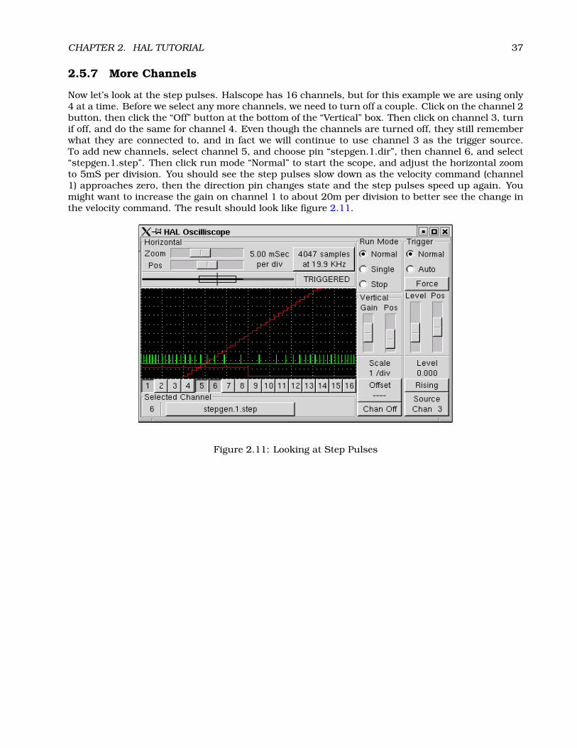
CHAPTER 2. HAL TUTORIAL 37
2.5.7 More Channels
Now let’s look at the step pulses. Halscope has 16 channels, but for this example we are using only4 at a time. Before we select any more channels, we need to turn off a couple. Click on the channel 2button, then click the “Off” button at the bottom of the “Vertical” box. Then click on channel 3, turnif off, and do the same for channel 4. Even though the channels are turned off, they still rememberwhat they are connected to, and in fact we will continue to use channel 3 as the trigger source.To add new channels, select channel 5, and choose pin “stepgen.1.dir”, then channel 6, and select“stepgen.1.step”. Then click run mode “Normal” to start the scope, and adjust the horizontal zoomto 5mS per division. You should see the step pulses slow down as the velocity command (channel1) approaches zero, then the direction pin changes state and the step pulses speed up again. Youmight want to increase the gain on channel 1 to about 20m per division to better see the change inthe velocity command. The result should look like figure 2.11.
Figure 2.11: Looking at Step Pulses
Part II
HAL Reference
38

Chapter 3
General Reference Information
3.1 Notation
3.1.1 Typographical Conventions
Command line examples are presented in bold typewriter font. Responses from the computerwill be in typewriter font. As of early 2006, there are no longer commands that require rootprivileges, so all examples will be preceded by the normal user prompt, $. Text inside squarebrackets [like-this] is optional. Text inside angle brackets <like-this> represents a field thatcan take on different values, and the adjacent paragraph will explain the appropriate values. Textitems separated by a vertical bar means that one or the other, but not both, should be present. Allcommand line examples assume that you are in the emc2/ directory, and you configured/compiledemc2 for the run-in-place scenario. Paths will be shown accordingly when needed.
3.1.2 Names
All HAL entities are accessed and manipulated by their names, so documenting the names of pins,signals, parameters, etc, is very important. HAL names are a maximum of 41 characters long (asdefined by HAL_NAME_LEN in hal.h). Many names will be presented in a general form, with textinside angle brackets <like-this> representing fields that can take on different values.When pins, signals, or parameters are described for the first time, their names will be preceededby their type in (SMALL CAPS) and followed by a brief description. A typical pin definition will looksomething like these examples:
• (BIT) parport.<portnum>.pin-<pinnum>-in – The HAL pin associated with the physicalinput pin <pinnum> on the 25 pin D-shell connector.
• (FLOAT) pid.<loopnum>.output – The output of the PID loop.
At times, a shortened version of a name may be used - for example the second pin above might bereferred to simply as .output when it can be done without causing confusion.
3.2 General Naming Conventions
Consistent naming conventions would make HAL much easier to use. For example, if every encoderdriver provided the same set of pins and named them the same way it would be easy to changefrom one type of encoder driver to another. Unfortunately, like many open-source projects, HAL isa combination of things that were designed, and things that simply evolved. As a result, there aremany inconsistencies. This section attempts to address that problem by defining some conventions,but it will probably be a while before all the modules are converted to follow them.
39

CHAPTER 3. GENERAL REFERENCE INFORMATION 40
Halcmd and other low-level HAL utilities treat HAL names as single entities, with no internal struc-ture. However, most modules do have some implicit structure. For example, a board providesseveral functional blocks, each block might have several channels, and each channel has one ormore pins. This results in a structure that resembles a directory tree. Even though halcmd doesn’trecognize the tree structure, proper choice of naming conventions will let it group related itemstogether (since it sorts the names). In addition, higher level tools can be designed to recognize suchstructure, if the names provide the neccessary information. To do that, all HAL modules shouldfollow these rules:
• Dots (“.”) separate levels of the heirarchy. This is analogous to the slash (“/”) in a filename.
• Hypens (“-”) separate words or fields in the same level of the heirarchy.
• HAL modules should not use underscores or “MixedCase”. 1
• Use only lowercase letters and numbers in names.
3.3 Hardware Driver Naming Conventions2
3.3.1 Pin/Parameter names
Hardware drivers should use five fields (on three levels) to make up a pin or parameter name, asfollows:
<device-name>.<device-num>.<io-type>.<chan-num>.<specific-name>
The individual fields are:
<device-name> The device that the driver is intended to work with. This is most often an interfaceboard of some type, but there are other possibilities.
<device-num> It is possible to install more than one servo board, parallel port, or other hardwaredevice in a computer. The device number identifies a specific device. Device numbers start at0 and increment.3
<io-type> Most devices provide more than one type of I/O. Even the simple parallel port has bothdigital inputs and digital outputs. More complex boards can have digital inputs and outputs,encoder counters, pwm or step pulse generators, analog-to-digital converters, digital-to-analogconverters, or other unique capabilities. The I/O type is used to identify the kind of I/O that apin or parameter is associated with. Ideally, drivers that implement the same I/O type, even iffor very different devices, should provide a consistent set of pins and parameters and identicalbehavior. For example, all digital inputs should behave the same when seen from inside theHAL, regardless of the device.
<chan-num> Virtually every I/O device has multiple channels, and the channel number identifiesone of them. Like device numbers, channel numbers start at zero and increment.4 If more thanone device is installed, the channel numbers on additional devices start over at zero. If it ispossible to have a channel number greater than 9, then channel numbers should be two digits,
1Underscores have all been removed, but there are still a few instances of mixed case, for example “pid.0.Pgain” insteadof “pid.0.p-gain”.
2Most drivers do not follow these conventions as of version 2.0. This chapter is really a guide for future development.3Some devices use jumpers or other hardware to attach a specific ID to each board. Ideally, the driver provides a way for
the user to specifically say “device-num 0 is the board with ID XXX”, and the device numbers always start at 0. However atpresent some drivers use the board ID directly as the device number. That means it is possible to have a device number 2,without a device 0. This is a bug and will be fixed in version 2.1.
4One glaring exception to the “channel numbers start at zero” rule is the parallel port. Its HAL pins are numbered withthe corresponding pin number on the DB-25 connector. This is convenient for wiring, but inconsistent with other drivers.There is some debate over whether this is a bug or a feature.

CHAPTER 3. GENERAL REFERENCE INFORMATION 41
with a leading zero on numbers less than 10 to preserve sort ordering. Some modules have pinsand/or parameters that affect more than one channel. For example a PWM generator mighthave four channels with four independent “duty-cycle” inputs, but one “frequency” parameterthat controls all four channels (due to hardware limitations). The frequency parameter shoulduse “0-3” as the channel number.
<specific-name> An individual I/O channel might have just a single HAL pin associated with it,but most have more than one. For example, a digital input has two pins, one is the state ofthe physical pin, the other is the same thing inverted. That allows the configurator to choosebetween active high and active low inputs. For most io-types, there is a standard set of pinsand parameters, (referred to as the “canonical interface”) that the driver should implement.The canonical interfaces are described in chapter 4.
3.3.1.1 Examples
motenc.0.encoder.2.position – the position output of the third encoder channel on the firstMotenc board.
stg.0.din.03.in – the state of the fourth digital input on the first Servo-to-Go board.
ppmc.0.pwm.00-03.frequency – the carrier frequency used for PWM channels 0 through 3.
3.3.2 Function Names
Hardware drivers usually only have two kinds of HAL functions, ones that read the hardware andupdate HAL pins, and ones that write to the hardware using data from HAL pins. They should benamed as follows:
<device-name>-<device-num>[.<io-type>[-<chan-num-range>]].read|write
<device-name> The same as used for pins and parameters.
<device-num> The specific device that the function will access.
<io-type> Optional. A function may access all of the I/O on a board, or it may access only acertain type. For example, there may be independent functions for reading encoder countersand reading digital I/O. If such independent functions exist, the <io-type> field identifies thetype of I/O they access. If a single function reads all I/O provided by the board, <io-type> isnot used.5
<chan-num-range> Optional. Used only if the <io-type> I/O is broken into groups and accessed bydifferent functions.
read|write Indicates whether the function reads the hardware or writes to it.
3.3.2.1 Examples
motenc.0.encoder.read – reads all encoders on the first motenc board
generic8255.0.din.09-15.read – reads the second 8 bit port on the first generic 8255 baseddigital I/O board
ppmc.0.write – writes all outputs (step generators, pwm, DACs, and digital) on the first ppmcboard
5Note to driver programmers: do NOT implement separate functions for different I/O types unless they are interruptableand can work in independent threads. If interrupting an encoder read, reading digital inputs, and then resuming the encoderread will cause problems, then implement a single function that does everything.

Chapter 4
Canonical Device Interfaces1
The following sections show the pins, parameters, and functions that are supplied by “canonicaldevices”. All HAL device drivers should supply the same pins and parameters, and implement thesame behavior.
Note that the only the <io-type> and <specific-name> fields are defined for a canonical device.The <device-name>, <device-num>, and <chan-num> fields are set based on the characteristics ofthe real device.
4.1 Digital Input
The canonical digital input (I/O type field: digin) is quite simple.
4.1.1 Pins
• (BIT) in – State of the hardware input.
• (BIT) in-not – Inverted state of the input.
4.1.2 Parameters
• None
4.1.3 Functions
• (FUNCT) read – Read hardware and set in and in-not HAL pins.
4.2 Digital Output
The canonical digital output (I/O type field: digout) is also very simple.
4.2.1 Pins
• (BIT) out – Value to be written (possibly inverted) to the hardware output.
1As of version 2.0, most of the HAL drivers don’t quite match up to the canonical interfaces defined here. In version 2.1,the drivers will be changed to match these specs.
42

CHAPTER 4. CANONICAL DEVICE INTERFACES 43
4.2.2 Parameters
• (BIT) invert – If TRUE, out is inverted before writing to the hardware.
4.2.3 Functions
• (FUNCT) write – Read out and invert, and set hardware output accordingly.
4.3 Analog Input
The canonical analog input (I/O type: adcin). This is expected to be used for analog to digitalconverters, which convert e.g. voltage to a continuous range of values.
4.3.1 Pins
• (FLOAT) value – The hardware reading, scaled according to the scale and offset parameters.Value = ((input reading, in hardware-dependent units) * scale) - offset
4.3.2 Parameters
• (FLOAT) scale – The input voltage (or current) will be multiplied by scale before being output tovalue.
• (FLOAT) offset – This will be subtracted from the hardware input voltage (or current) after thescale multiplier has been applied.
• (FLOAT) bit_weight – The value of one least significant bit (LSB). This is effectively the granu-larity of the input reading.
• (FLOAT) hw_offset – The value present on the input when 0 volts is applied to the input pin(s).
4.3.3 Functions
• (FUNCT) read – Read the values of this analog input channel. This may be used for individualchannel reads, or it may cause all channels to be read
4.4 Analog Output
The canonical analog output (I/O Type: adcout). This is intended for any kind of hardware thatcan output a more-or-less continuous range of values. Examples are digital to analog converters orPWM generators.
Pins
• (FLOAT) value – The value to be written. The actual value output to the hardware will dependon the scale and offset parameters.
• (BIT) enable – If false, then output 0 to the hardware, regardless of the value pin.

CHAPTER 4. CANONICAL DEVICE INTERFACES 44
4.4.1 Parameters
• (FLOAT) offset – This will be added to the value before the hardware is updated
• (FLOAT) scale – This should be set so that an input of 1 on the value pin will cause 1V
• (FLOAT) high_limit (optional) – When calculating the value to output to the hardware, if value+ offset is greater than high_limit, then high_limit will be used instead.
• (FLOAT) low_limit (optional) – When calculating the value to output to the hardware, if value +offset is less than low_limit, then low_limit will be used instead.
• (FLOAT) bit_weight (optional) – The value of one least significant bit (LSB), in volts (or mA, forcurrent outputs)
• (FLOAT) hw_offset (optional) – The actual voltage (or current) that will be output if 0 is writtento the hardware.
4.4.2 Functions
(FUNCT) write – This causes the calculated value to be output to the hardware. If enable is false,then the output will be 0, regardles of value, scale, and offset. The meaning of “0” is dependent onthe hardware. For example, a bipolar 12-bit A/D may need to write 0x1FF (mid scale) to the D/Aget 0 volts from the hardware pin. If enable is true, read scale, offset and value and output to theadc (scale * value) + offset. If enable is false, then output 0.
4.5 Encoder
The canonical encoder interface (I/O type field: encoder ) provides the functionality needed forhoming to an index pulse and doing spindle synchronization, as well as basic position and/or ve-locity control. This interface should be implementable regardless of the actual underlying hardware,although some hardware will provide “better” results. (For example, capture the index position to+/- 1 count while moving faster, or have less jitter on the velocity pin.)
4.5.1 Pins
• (S32) count – Encoder value in counts.
• (FLOAT) position – Encoder value in position units (see parameter “scale”).
• (FLOAT) velocity – Velocity in position units per second.
• (BIT) reset – When True, force counter to zero.
• (BIT) index-enable – (bidirectional) When True, reset to zero on next index pulse, and set pinFalse.
The “index-enable” pin is bi-directional, and might require a little more explanation. If “index-enable” is False, the index channel of the encoder will be ignored, and the counter will countnormally. The encoder driver will never set “index-enable” True. However, some other componentmay do so. If “index-enable” is True, then when the next index pulse arrives, the encoder counterwill be reset to zero, and the driver will set “index-enable” False. That will let the other componentknow that an index pulse arrived. This is a form of handshaking - the other component sets “index-enable” True to request a index pulse reset, and the driver sets it False when the request has beensatisfied.
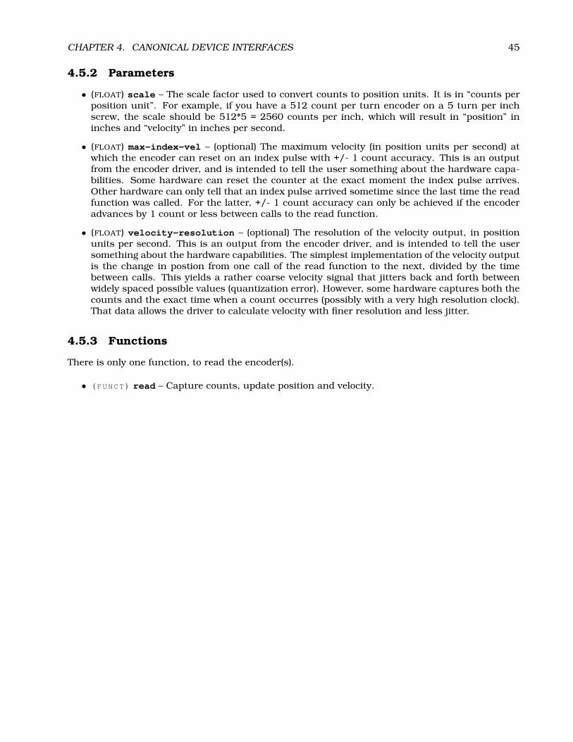
CHAPTER 4. CANONICAL DEVICE INTERFACES 45
4.5.2 Parameters
• (FLOAT) scale – The scale factor used to convert counts to position units. It is in “counts perposition unit”. For example, if you have a 512 count per turn encoder on a 5 turn per inchscrew, the scale should be 512*5 = 2560 counts per inch, which will result in “position” ininches and “velocity” in inches per second.
• (FLOAT) max-index-vel – (optional) The maximum velocity (in position units per second) atwhich the encoder can reset on an index pulse with +/- 1 count accuracy. This is an outputfrom the encoder driver, and is intended to tell the user something about the hardware capa-bilities. Some hardware can reset the counter at the exact moment the index pulse arrives.Other hardware can only tell that an index pulse arrived sometime since the last time the readfunction was called. For the latter, +/- 1 count accuracy can only be achieved if the encoderadvances by 1 count or less between calls to the read function.
• (FLOAT) velocity-resolution – (optional) The resolution of the velocity output, in positionunits per second. This is an output from the encoder driver, and is intended to tell the usersomething about the hardware capabilities. The simplest implementation of the velocity outputis the change in postion from one call of the read function to the next, divided by the timebetween calls. This yields a rather coarse velocity signal that jitters back and forth betweenwidely spaced possible values (quantization error). However, some hardware captures both thecounts and the exact time when a count occurres (possibly with a very high resolution clock).That data allows the driver to calculate velocity with finer resolution and less jitter.
4.5.3 Functions
There is only one function, to read the encoder(s).
• (FUNCT) read – Capture counts, update position and velocity.

Chapter 5
Tools and Utilities
5.1 Halcmd
Halcmd is a command line tool for manipulating the HAL. There is a rather complete man page forhalcmd, which will be installed if you have installed EMC2 from either source or a package. If youhave compiled EMC2 for “run-in-place”, the man page is not installed, but it is accessible. From themain EMC2 directory, do:
$ man -M docs/man halcmd
Chapter 2 has a number of examples of halcmd usage, and is a good tutorial for halcmd, while thissection is a detailed reference listing all of the available commands.
5.1.1 Usage
halcmd [<options>] [<command>[<args>]]
5.1.2 Options
-f [<filename>]
File mode: Ignores commands on command line, takes input from <filename> instead. If <filename>is not specified, takes input from stdin.
-k
Keep going after failed command(s). The default is to stop and return failure if any command fails.
-q
Quiet: Prints messages only when errors occur. This is the default.
-Q
Extra quiet: Prints nothing, executes commands silently. Note that some commands like show andsave do nothing except print some information. Giving the -Q option to one of those commandsprevents the information from being printed, making the command pointless.
-s
46

CHAPTER 5. TOOLS AND UTILITIES 47
Script mode: Modified how show outputs information. Supresses headers, and prints most lists(e.g. thread functions, signal pins) on a single line. Suppresses the halcmd: prompt if -f is alsospecified (for use by other programs that issue commands via a pipe).
-v
Verbose: Prints messages showing the results of each command.
-V
Extra Verbose: Prints lots of debugging messages. Very messy, not normally used.
-h
Help: Prints a help screen and exits.
5.1.3 Commands
Commands tell halcmd what to do. If invoked without the -f option, halcmd reads the remainder ofthe command line and treats it as a single command. If invoked with the -f option, halcmd readsthe specified file and treats each line as a command. The -f option allows you to very quickly executea whole series of commands, and is the most common way to configure the HAL.
#
Commands starting with ’#’ are considered to be comments, and are ignored by halcmd.
5.1.3.1 Loading/unloading modules
loadrt <compname> [<arg1>] [<arg2>]
Load realtime component: Loads the realtime HAL component <compname>, passing it configurationarguments <arg1>, <arg2>, etc. Halcmd uses the external program emc_module_helper to load themodule. If <compname> is not found in the directory that emc_module_helper expects to contain thecomponents, the command will fail.
unloadrt <compname>
Unload realtime component: Unloads the realtime HAL component <compname>. Halcmd usesthe external program emc_module_helper to unload the module. If <compname> is not loaded, thecommand will fail.
5.1.3.2 Creating Signals
newsig <signame> <type>
New signal: Creates a new HAL signal called <signame> that may later be used to connect two ormore HAL pins. <type> is the data type of the new signal, and must be one of bit, s8, u8, s16,u16, s32, u32, or float. If a signal of the same name already exists, the command will fail.
delsig <signame>
Delete signal: Deletes a HAL signal called <signame>. Any pins currently linked to the signal willbe unlinked. If a signal called <signame> does not exist, the command will fail.
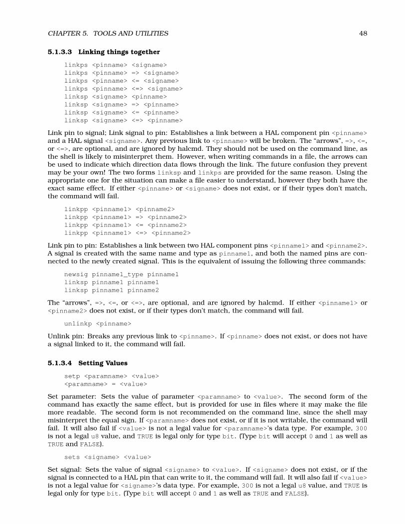
CHAPTER 5. TOOLS AND UTILITIES 48
5.1.3.3 Linking things together
linkps <pinname> <signame>linkps <pinname> => <signame>linkps <pinname> <= <signame>linkps <pinname> <=> <signame>linksp <signame> <pinname>linksp <signame> => <pinname>linksp <signame> <= <pinname>linksp <signame> <=> <pinname>
Link pin to signal; Link signal to pin: Establishes a link between a HAL component pin <pinname>and a HAL signal <signame>. Any previous link to <pinname> will be broken. The “arrows”, =>, <=,or <=>, are optional, and are ignored by halcmd. They should not be used on the command line, asthe shell is likely to misinterpret them. However, when writing commands in a file, the arrows canbe used to indicate which direction data flows through the link. The future confusion they preventmay be your own! The two forms linksp and linkps are provided for the same reason. Using theappropriate one for the situation can make a file easier to understand, however they both have theexact same effect. If either <pinname> or <signame> does not exist, or if their types don’t match,the command will fail.
linkpp <pinname1> <pinname2>linkpp <pinname1> => <pinname2>linkpp <pinname1> <= <pinname2>linkpp <pinname1> <=> <pinname2>
Link pin to pin: Establishes a link between two HAL component pins <pinname1> and <pinname2>.A signal is created with the same name and type as pinname1, and both the named pins are con-nected to the newly created signal. This is the equivalent of issuing the following three commands:
newsig pinname1_type pinname1linksp pinname1 pinname1linksp pinname1 pinname2
The “arrows”, =>, <=, or <=>, are optional, and are ignored by halcmd. If either <pinname1> or<pinname2> does not exist, or if their types don’t match, the command will fail.
unlinkp <pinname>
Unlink pin: Breaks any previous link to <pinname>. If <pinname> does not exist, or does not havea signal linked to it, the command will fail.
5.1.3.4 Setting Values
setp <paramname> <value><paramname> = <value>
Set parameter: Sets the value of parameter <paramname> to <value>. The second form of thecommand has exactly the same effect, but is provided for use in files where it may make the filemore readable. The second form is not recommended on the command line, since the shell maymisinterpret the equal sign. If <paramname> does not exist, or if it is not writable, the command willfail. It will also fail if <value> is not a legal value for <paramname>’s data type. For example, 300is not a legal u8 value, and TRUE is legal only for type bit. (Type bit will accept 0 and 1 as well asTRUE and FALSE).
sets <signame> <value>
Set signal: Sets the value of signal <signame> to <value>. If <signame> does not exist, or if thesignal is connected to a HAL pin that can write to it, the command will fail. It will also fail if <value>is not a legal value for <signame>’s data type. For example, 300 is not a legal u8 value, and TRUE islegal only for type bit. (Type bit will accept 0 and 1 as well as TRUE and FALSE).
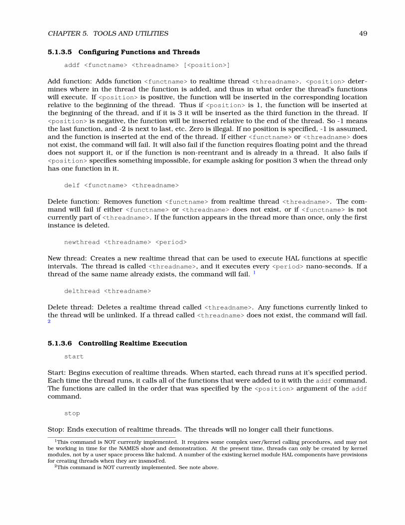
CHAPTER 5. TOOLS AND UTILITIES 49
5.1.3.5 Configuring Functions and Threads
addf <functname> <threadname> [<position>]
Add function: Adds function <functname> to realtime thread <threadname>. <position> deter-mines where in the thread the function is added, and thus in what order the thread’s functionswill execute. If <position> is positive, the function will be inserted in the corresponding locationrelative to the beginning of the thread. Thus if <position> is 1, the function will be inserted atthe beginning of the thread, and if it is 3 it will be inserted as the third function in the thread. If<position> is negative, the function will be inserted relative to the end of the thread. So -1 meansthe last function, and -2 is next to last, etc. Zero is illegal. If no position is specified, -1 is assumed,and the function is inserted at the end of the thread. If either <functname> or <threadname> doesnot exist, the command will fail. It will also fail if the function requires floating point and the threaddoes not support it, or if the function is non-reentrant and is already in a thread. It also fails if<position> specifies something impossible, for example asking for position 3 when the thread onlyhas one function in it.
delf <functname> <threadname>
Delete function: Removes function <functname> from realtime thread <threadname>. The com-mand will fail if either <functname> or <threadname> does not exist, or if <functname> is notcurrently part of <threadname>. If the function appears in the thread more than once, only the firstinstance is deleted.
newthread <threadname> <period>
New thread: Creates a new realtime thread that can be used to execute HAL functions at specificintervals. The thread is called <threadname>, and it executes every <period> nano-seconds. If athread of the same name already exists, the command will fail. 1
delthread <threadname>
Delete thread: Deletes a realtime thread called <threadname>. Any functions currently linked tothe thread will be unlinked. If a thread called <threadname> does not exist, the command will fail.2
5.1.3.6 Controlling Realtime Execution
start
Start: Begins execution of realtime threads. When started, each thread runs at it’s specified period.Each time the thread runs, it calls all of the functions that were added to it with the addf command.The functions are called in the order that was specified by the <position> argument of the addfcommand.
stop
Stop: Ends execution of realtime threads. The threads will no longer call their functions.
1This command is NOT currently implemented. It requires some complex user/kernel calling procedures, and may notbe working in time for the NAMES show and demonstration. At the present time, threads can only be created by kernelmodules, not by a user space process like halcmd. A number of the existing kernel module HAL components have provisionsfor creating threads when they are insmod’ed.
2This command is NOT currently implemented. See note above.
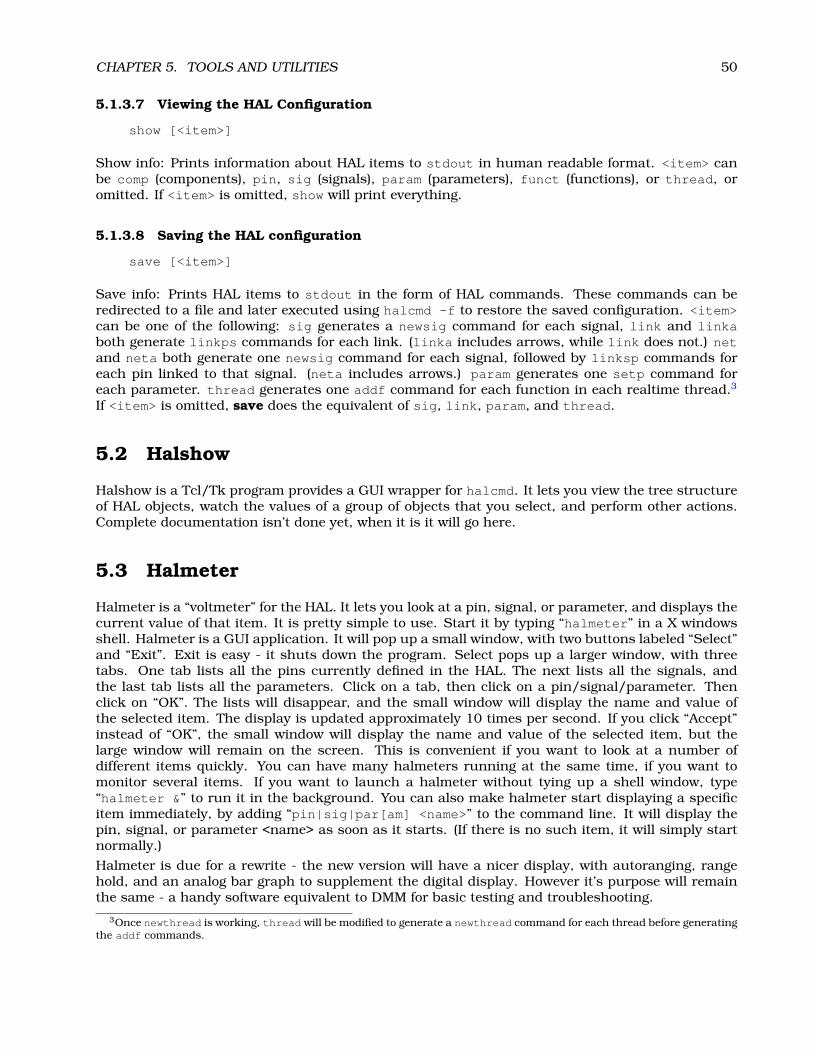
CHAPTER 5. TOOLS AND UTILITIES 50
5.1.3.7 Viewing the HAL Configuration
show [<item>]
Show info: Prints information about HAL items to stdout in human readable format. <item> canbe comp (components), pin, sig (signals), param (parameters), funct (functions), or thread, oromitted. If <item> is omitted, show will print everything.
5.1.3.8 Saving the HAL configuration
save [<item>]
Save info: Prints HAL items to stdout in the form of HAL commands. These commands can beredirected to a file and later executed using halcmd -f to restore the saved configuration. <item>can be one of the following: sig generates a newsig command for each signal, link and linkaboth generate linkps commands for each link. (linka includes arrows, while link does not.) netand neta both generate one newsig command for each signal, followed by linksp commands foreach pin linked to that signal. (neta includes arrows.) param generates one setp command foreach parameter. thread generates one addf command for each function in each realtime thread.3
If <item> is omitted, save does the equivalent of sig, link, param, and thread.
5.2 Halshow
Halshow is a Tcl/Tk program provides a GUI wrapper for halcmd. It lets you view the tree structureof HAL objects, watch the values of a group of objects that you select, and perform other actions.Complete documentation isn’t done yet, when it is it will go here.
5.3 Halmeter
Halmeter is a “voltmeter” for the HAL. It lets you look at a pin, signal, or parameter, and displays thecurrent value of that item. It is pretty simple to use. Start it by typing “halmeter” in a X windowsshell. Halmeter is a GUI application. It will pop up a small window, with two buttons labeled “Select”and “Exit”. Exit is easy - it shuts down the program. Select pops up a larger window, with threetabs. One tab lists all the pins currently defined in the HAL. The next lists all the signals, andthe last tab lists all the parameters. Click on a tab, then click on a pin/signal/parameter. Thenclick on “OK”. The lists will disappear, and the small window will display the name and value ofthe selected item. The display is updated approximately 10 times per second. If you click “Accept”instead of “OK”, the small window will display the name and value of the selected item, but thelarge window will remain on the screen. This is convenient if you want to look at a number ofdifferent items quickly. You can have many halmeters running at the same time, if you want tomonitor several items. If you want to launch a halmeter without tying up a shell window, type“halmeter &” to run it in the background. You can also make halmeter start displaying a specificitem immediately, by adding “pin|sig|par[am] <name>” to the command line. It will display thepin, signal, or parameter <name> as soon as it starts. (If there is no such item, it will simply startnormally.)
Halmeter is due for a rewrite - the new version will have a nicer display, with autoranging, rangehold, and an analog bar graph to supplement the digital display. However it’s purpose will remainthe same - a handy software equivalent to DMM for basic testing and troubleshooting.
3Once newthread is working, thread will be modified to generate a newthread command for each thread before generatingthe addf commands.

CHAPTER 5. TOOLS AND UTILITIES 51
5.4 Halscope
Halscope is an “oscilloscope” for the HAL. It lets you capture the value of pins, signals, and param-eters as a function of time. Complete operating instructions should be located here eventually. Fornow, refer to section 2.5 in the tutorial chapter, which explains the basics.

Chapter 6
Hardware Drivers
6.1 Parport
Parport is a driver for the traditional PC parallel port. The port has a total of 17 physical pins. Theoriginal parallel port divided those pins into three groups: data, control, and status. The data groupconsists of 8 output pins, the control group consists of 4 output pins, and the status group is 5input pins. In the early 1990’s, the bidirectional parallel port was introduced, which allows the datagroup to be used for output or input. The HAL driver supports the bidirectional port, and allows theuser to set the data group as either input or output. If configured as output, a port provides a totalof 12 outputs and 5 inputs. If configured as input, it provides 4 outputs and 13 inputs. No othercombinations are supported, and a port cannot be changed from input to output once the driveris installed. Figure 6.1 shows two block diagrams, one showing the driver when the data group isconfigured for output, and one showing it configured for input.There are actually two versions of the parport driver. One is a kernel module, and provides realtimecontrol of the parallel port. The other is a user space process, and is not realtime. The non-realtimeversion is intended mainly for testing, and is not recommended for most applications. Using boththe realtime and non-realtime versions at the same time is a bad idea.The parport driver can control up to 8 ports (defined by MAX_PORTS in hal_parport.c). The portsare numbered starting at zero.
6.1.1 Installing
Realtime version, from command line:
emc2$ bin/halcmd loadrt hal_parport ’cfg=”<config-string>”’1
Realtime version, from a file:
loadrt hal_parport cfg=”<config-string>”
Non-realtime version:
emc2# bin/hal_parport <config-string> &
The config string consists of a hex port address, followed by an optional direction, repeated for eachport. The direction is either “in” or “out” and determines the direction of the physical pins 2 through9. If the direction is not specified, the data group defaults to output. For example:
1The single quotes around the entire cfg= argument are needed to prevent the shell from misinterpreting the doublequotes around the string, and any spaces or special characters in the string. Single quotes should not be used in a file orfrom the halcmd prompt.
52

CHAPTER 6. HARDWARE DRIVERS 53
emc2# bin/hal_parport 278 378 in 20A0 out
This example installs drivers for one port at 0x0278, with pins 2-9 as outputs (by default, sinceneither “in” nor “out” was specified), one at 0x0378, with pins 2-9 as inputs, and one at 0x20A0,with pins 2-9 explicitly specified as outputs. Note that you must know the base address of theparallel port to properly configure the driver. For ISA bus ports, this is usually not a problem,since the port is almost always at a “well known” address, like 0278 or 0378. However PCI portsmay at nearly any address, and finding the address can be tricky2. There is no default address - if<config-string> does not contain at least one address, it is an error.
6.1.2 Removing
Realtime version:
emc2$ bin/halcmd unloadrt hal_parport
Non-realtime version:
Remove the non-realtime version by sending SIGINT or SIGTERM.
6.1.3 Pins
• (BIT) parport.<portnum>.pin-<pinnum>-out – Drives a physical output pin.
• (BIT) parport.<portnum>.pin-<pinnum>-in – Tracks a physical input pin.
• (BIT) parport.<portnum>.pin-<pinnum>-in-not – Tracks a physical input pin, but in-verted.
For each pin, <portnum> is the port number, and <pinnum> is the physical pin number in the 25pin D-shell connector.
For each physical output pin, the driver creates a single HAL pin, for example parport.0.pin-14-out.Pins 1, 14, 16, and 17 are always outputs. Pins 2 through 9 are part of the data group and areoutput pins if the port is defined as an output port. (Output is the default.) These HAL pins controlthe state of the corresponding physical pins.
For each physical input pin, the driver creates two HAL pins, for example parport.0.pin-12-inand parport.0.pin-12-in-not. Pins 10, 11, 12, 13, and 15 are always input pins. Pins 2 through9 are input pins only if the port is defined as an input port. The -in HAL pin is TRUE if the physicalpin is high, and FALSE if the physical pin is low. The -in-not HAL pin is inverted – it is FALSEif the physical pin is high. By connecting a signal to one or the other, the user can determine thestate of the input.
6.1.4 Parameters
• (BIT) parport.<portnum>.pin-<pinnum>-out-invert – Inverts an output pin.
The -invert parameter determines whether an output pin is active high or active low. If -invertis FALSE, setting the HAL -out pin TRUE drives the physical pin high, and FALSE drives it low. If-invert is TRUE, then setting the HAL -out pin TRUE will drive the physical pin low.
2Perhaps a future version of this driver will attempt to auto-identify PCI port addresses - however, it is very importantthat the user (or system integrator) makes sure the ports are configured correctly. Sending step and direction pulses toa LaserJet by accident simply wastes paper, but spooling a print job to stepper or servo motors could cause unexpectedmachine movement and possibly serious or fatal injuries.

CHAPTER 6. HARDWARE DRIVERS 54
pin-
8-in
-not
pin-
8-in
pin-
7-in
-not
pin-
7-in
pin-
6-in
-not
pin-
6-in
pin-
5-in
-not
pin-
5-in
pin-
4-in
-not
pin-
4-in
pin-
3-in
-not
pin-
3-in
pin-
2-in
-not
pin-
2-in
pin-
9-in
-not
pin-
9-in
pin-
15-in
-not
pin-
15-in
pin-
13-in
-not
pin-
13-in
pin-
12-in
-not
pin-
12-in
pin-
11-in
-not
pin-
11-in
pin-
10-in
-not
pin-
10-in
pin-
17-o
ut-in
vert
pin-
17-o
ut
pin-
16-o
ut-in
vert
pin-
16-o
ut
pin-
14-o
ut-in
vert
pin-
14-o
ut
pin-
1-ou
t-in
vert
pin-
1-ou
t
pin-
10-in
-not
pin-
10-in
pin-
11-in
-not
pin-
11-in
pin-
12-in
-not
pin-
12-in
pin-
13-in
-not
pin-
13-in
pin-
15-in
-not
pin-
15-in
pin-
8-ou
t-in
vert
pin-
8-ou
t
pin-
7-ou
t-in
vert
pin-
7-ou
t
pin-
6-ou
t-in
vert
pin-
6-ou
t
pin-
5-ou
t-in
vert
pin-
5-ou
t
pin-
4-ou
t-in
vert
pin-
4-ou
t
pin-
3-ou
t-in
vert
pin-
3-ou
t
pin-
2-ou
t-in
vert
pin-
2-ou
t
pin-
9-ou
t-in
vert
pin-
9-ou
t
pin-
17-o
ut-in
vert
pin-
17-o
ut
pin-
16-o
ut-in
vert
pin-
16-o
ut
pin-
14-o
ut-in
vert
pin-
14-o
ut
pin-
1-ou
t-in
vert
pin-
1-ou
t
2525
1313
2424
1212
1111
1010
99
88
77
66
55
44
33
22
11
2323
2222
2121
2020
1919
1818
1717
1616
1515
1414
parp
ort.
0pa
rpor
t.0
conf
igur
ed a
s in
put
conf
igur
ed a
s ou
tput
Figure 6.1: Parport Block Diagram

CHAPTER 6. HARDWARE DRIVERS 55
6.1.5 Functions
• (FUNCT) parport.<portnum>.read– Reads physical input pins of port <portnum> and up-dates HAL -in and -in-not pins.
• (FUNCT) parport.read-all – Reads physical input pins of all ports and updates HAL -inand -in-not pins.
• (FUNCT) parport.<portnum>.write – Reads HAL -out pins of port <portnum> and updatesthat port’s physical output pins.
• (FUNCT) parport.write-all – Reads HAL -out pins of all ports and updates all physicaloutput pins.
The individual functions are provided for situations where one port needs to be updated in a veryfast thread, but other ports can be updated in a slower thread to save CPU time. It is probably nota good idea to use both an -all function and an individual function at the same time.The user space version of the driver cannot export functions, instead it exports parameters withthe same names. Then the driver sits in a loop checking the parameters. If they are zero, it doesnothing. If any parameter is greater than zero, the corresponding function runs once, then theparameter is reset to zero. If any parameter is less than zero, the corresponding function runs onevery pass through the loop. The driver will loop forever, until it receives either SIGINT (ctrl-C) orSIGTERM, at which point it cleans up and exits.
6.2 AX5214H
The Axiom Measurement & Control AX5214H is a 48 channel digital I/O board. It plugs into a PCIbus, and resembles a pair of 8255 chips.3
6.2.1 Installing
From command line:
emc2$ bin/halcmd loadrt hal_ax5214h ’cfg=”<config-string>”’4
From a file:
loadrt hal_ax5214h cfg=”<config-string>”
The config string consists of a hex port address, followed by an 8 character string of “I” and “O”which sets groups of pins as inputs and outputs. The first two character set the direction of thefirst two 8 bit blocks of pins (0-7 and 8-15). The next two set blocks of 4 pins (16-19 and 20-23). Thepattern then repeats, two more blocks of 8 bits (24-31 and 32-39) and two blocks of 4 bits (40-43and 44-47). If more than one board is installed, the data for the second board follows the first. Asan example, the string “0x220 IIIOIIOO 0x300 OIOOIOIO” installs drivers for two boards. Thefirst board is at address 0x220, and has 36 inputs (0-19 and 24-39) and 12 outputs (20-23 and40-47). The second board is at address 0x300, and has 20 inputs (8-15, 24-31, and 40-43) and 28outputs (0-7. 16-23, 32-39, and 44-47).
6.2.2 Removing
emc2$ bin/halcmd unloadrt hal_ax52143In fact it may be a pair of 8255 chips, but I’m not sure. If/when someone starts a driver for an 8255 they should look at
the ax5214 code, much of the work is already done.4The single quotes around the entire cfg= argument are needed to prevent the shell from misinterpreting the double
quotes around the string, and any spaces or special characters in the string. Single quotes should not be used in a file orfrom the halcmd prompt.
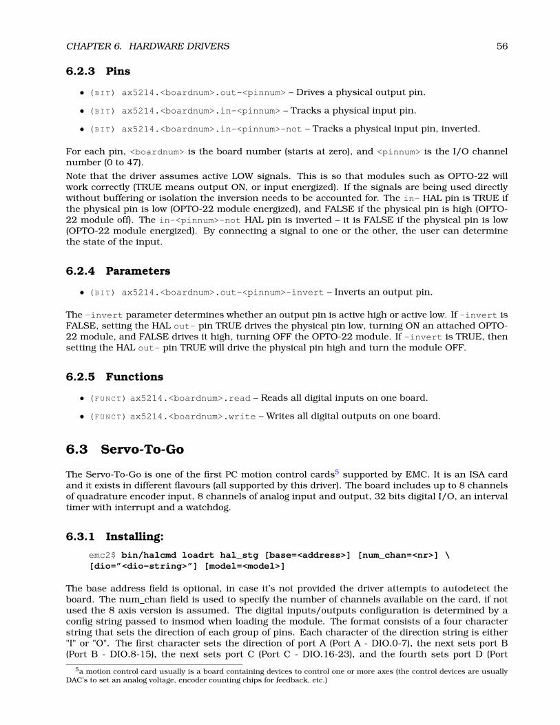
CHAPTER 6. HARDWARE DRIVERS 56
6.2.3 Pins
• (BIT) ax5214.<boardnum>.out-<pinnum> – Drives a physical output pin.
• (BIT) ax5214.<boardnum>.in-<pinnum> – Tracks a physical input pin.
• (BIT) ax5214.<boardnum>.in-<pinnum>-not – Tracks a physical input pin, inverted.
For each pin, <boardnum> is the board number (starts at zero), and <pinnum> is the I/O channelnumber (0 to 47).
Note that the driver assumes active LOW signals. This is so that modules such as OPTO-22 willwork correctly (TRUE means output ON, or input energized). If the signals are being used directlywithout buffering or isolation the inversion needs to be accounted for. The in- HAL pin is TRUE ifthe physical pin is low (OPTO-22 module energized), and FALSE if the physical pin is high (OPTO-22 module off). The in-<pinnum>-not HAL pin is inverted – it is FALSE if the physical pin is low(OPTO-22 module energized). By connecting a signal to one or the other, the user can determinethe state of the input.
6.2.4 Parameters
• (BIT) ax5214.<boardnum>.out-<pinnum>-invert – Inverts an output pin.
The -invert parameter determines whether an output pin is active high or active low. If -invert isFALSE, setting the HAL out- pin TRUE drives the physical pin low, turning ON an attached OPTO-22 module, and FALSE drives it high, turning OFF the OPTO-22 module. If -invert is TRUE, thensetting the HAL out- pin TRUE will drive the physical pin high and turn the module OFF.
6.2.5 Functions
• (FUNCT) ax5214.<boardnum>.read – Reads all digital inputs on one board.
• (FUNCT) ax5214.<boardnum>.write – Writes all digital outputs on one board.
6.3 Servo-To-Go
The Servo-To-Go is one of the first PC motion control cards5 supported by EMC. It is an ISA cardand it exists in different flavours (all supported by this driver). The board includes up to 8 channelsof quadrature encoder input, 8 channels of analog input and output, 32 bits digital I/O, an intervaltimer with interrupt and a watchdog.
6.3.1 Installing:
emc2$ bin/halcmd loadrt hal_stg [base=<address>] [num_chan=<nr>] \[dio=”<dio-string>”] [model=<model>]
The base address field is optional, in case it’s not provided the driver attempts to autodetect theboard. The num_chan field is used to specify the number of channels available on the card, if notused the 8 axis version is assumed. The digital inputs/outputs configuration is determined by aconfig string passed to insmod when loading the module. The format consists of a four characterstring that sets the direction of each group of pins. Each character of the direction string is either"I" or "O". The first character sets the direction of port A (Port A - DIO.0-7), the next sets port B(Port B - DIO.8-15), the next sets port C (Port C - DIO.16-23), and the fourth sets port D (Port
5a motion control card usually is a board containing devices to control one or more axes (the control devices are usuallyDAC’s to set an analog voltage, encoder counting chips for feedback, etc.)

CHAPTER 6. HARDWARE DRIVERS 57
D - DIO.24-31). The model field can be used in case the driver doesn’t autodetect the right cardversion6. For example:
emc2$ bin/halcmd loadrt hal_stg base=0x300 num_chan=4 dio=”IOIO”
This example installs the stg driver for a card found at the base address of 0x300, 4 channels ofencoder feedback, DAC’s and ADC’s, along with 32 bits of I/O configured like this: the first 8 (PortA) configured as Input, the next 8 (Port B) configured as Output, the next 8 (Port C) configured asInput, and the last 8 (Port D) configured as Output
emc2$ bin/halcmd loadrt hal_stg
This example installs the driver and attempts to autodetect the board address and board model, itinstalls 8 axes by default along with a standard I/O setup: Port A & B configured as Input, Port C& D configured as Output.
6.3.2 Removing
emc2$ bin/halcmd unloadrt hal_stg
6.3.3 Pins
• (S32) stg.<channel>.counts – Tracks the counted encoder ticks.
• (FLOAT) stg.<channel>.position – Outputs a converted position.
• (FLOAT) stg.<channel>.dac-value – Drives the voltage for the corresponding DAC.
• (FLOAT) stg.<channel>.adc-value – Tracks the measured voltage from the correspondingADC.
• (BIT) stg.in-<pinnum> – Tracks a physical input pin.
• (BIT) stg.in-<pinnum>-not – Tracks a physical input pin, but inverted.
• (BIT) stg.out-<pinnum> – Drives a physical output pin
For each pin, <channel> is the axis number, and <pinnum> is the logic pin number of the STG7.
The in- HAL pin is TRUE if the physical pin is high, and FALSE if the physical pin is low. Thein-<pinnum>-not HAL pin is inverted – it is FALSE if the physical pin is high. By connecting asignal to one or the other, the user can determine the state of the input.
6.3.4 Parameters
• (FLOAT) stg.<channel>.position-scale – The number of counts / user unit (to convertfrom counts to units).
• (FLOAT) stg.<channel>.dac-offset – Sets the offset for the corresponding DAC.
• (FLOAT) stg.<channel>.dac-gain – Sets the gain of the corresponding DAC.
• (FLOAT) stg.<channel>.adc-offset – Sets the offset of the corresponding ADC.
• (FLOAT) stg.<channel>.adc-gain – Sets the gain of the corresponding ADC.
6hint: after starting up the driver, ’dmesg’ can be consulted for messages relevant to the driver (e.g. autodetected versionnumber and base address)
7if IIOO is defined, there are 16 input pins (in-00 .. in-15) and 16 output pins (out-00 .. out-15), and they correspond toPORTs ABCD (in-00 is PORTA.0, out-15 is PORTD.7)

CHAPTER 6. HARDWARE DRIVERS 58
• (BIT) stg.out-<pinnum>-invert – Inverts an output pin.
The -invert parameter determines whether an output pin is active high or active low. If -invertis FALSE, setting the HAL out- pin TRUE drives the physical pin high, and FALSE drives it low. If-invert is TRUE, then setting the HAL out- pin TRUE will drive the physical pin low.
6.3.5 Functions
• (FUNCT) stg.capture-position – Reads the encoder counters from the axis <channel>.
• (FUNCT) stg.write-dacs – Writes the voltages to the DACs.
• (FUNCT) stg.read-adcs – Reads the voltages from the ADCs.
• (FUNCT) stg.di-read – Reads physical in- pins of all ports and updates all HAL in- andin-<pinnum>-not pins.
• (FUNCT) stg.do-write – Reads all HAL out- pins and updates all physical output pins.
6.4 Mesa Electronics m5i20 “Anything I/O Card”
The Mesa Electronics m5i20 card consists of an FPGA that can be loaded with a wide variety ofconfigurations, and has 72 pins that leave the PC. The assignment of the pins depends on theFPGA configuration. Currently there is a HAL driver for the “4 axis host based motion control”configuration, and this FPGA configurations is also provided with EMC2. It provides 8 encodercounters, 4 PWM outputs (normally used as DACs) and up to 48 digital I/O channels, 32 inputsand 16 outputs.8
Installing:
emc2$ bin/halcmd loadrt hal_m5i20 [loadFpga=1|0] [dacRate=<rate>]
If loadFpga is 1 (the default) the driver will load the FPGA configuration on startup. If it is 0, thedriver assumes the configuration is already loaded. dacRate sets the carrier frequency for the PWMoutputs, in Hz. The default is 32000, for 32KHz PWM.9 The driver prints some usefull debuggingmessage to the kernel log, which can be viewed with dmesg.
6.4.1 Removing
emc2$ bin/halcmd unloadrt hal_m5i20
6.4.2 Pins
In the following pins, parameters, and functions, <board> is the board ID. According to the namingconventions the first board should always have an ID of zero, however this driver uses the PCI boardID, so it may be non-zero even if there is only one board.
• (S32) m5i20.<board>.enc-<channel>-count – Encoder position, in counts.
• (S32) m5i20.<board>.enc-<channel>-cnt-latch – Position in counts when index pulsearrived.
8Ideally the encoders, “DACs”, and digital I/O would comply with the canonical interfaces defined earlier, but they don’t.Fixing that is on the things-to-do list.
9I don’t know what the maximum (and minimum, if any) PWM frequency is, it should be documented here. Also, this isthe kind of thing that ideally is controlled by a HAL parameter, rather than being set when the driver is initially loaded. Idon’t know if that is possible, it depends on the hardware and I don’t have the neccessary information.

CHAPTER 6. HARDWARE DRIVERS 59
• (FLOAT) m5i20.<board>.enc-<channel>-position – Encoder position, in user units.
• (FLOAT) m5i20.<board>.enc-<channel>-pos-latch – Position in user units when indexpulse arrived.
• (BIT) m5i20.<board>.enc-<channel>-index – Current status of index pulse input?
• (BIT) m5i20.<board>.enc-<channel>-idx-latch – Goes true when an index pulse arrives?
• (BIT) m5i20.<board>.enc-<channel>-latch-index – Bidirectional - used to control/reportindex latching?
• (BIT) m5i20.<board>.enc-<channel>-reset-count – Bidirectional (why?) - used to resetcounter?
• (BIT) m5i20.<board>.dac-<channel>-enable – Enables DAC if true. DAC outputs zerovolts if false?
• (FLOAT) m5i20.<board>.dac-<channel>-value – Analog output value for PWM “DAC” (inuser units, see -scale and -offset)
• (BIT) m5i20.<board>.in-<channel> – State of digital input pin, see canonical digital input.
• (BIT) m5i20.<board>.in-<channel>-not – Inverted state of digital input pin, see canonicaldigital input.
• (BIT) m5i20.<board>.out-<channel> – Value to be written to digital output, see canonicaldigital output.
• (BIT) m5i20.<board>.estop-in – Dedicated estop input, more details needed.
• (BIT) m5i20.<board>.estop-in-not – Inverted state of dedicated estop input.
• (BIT) m5i20.<board>.watchdog-reset – Bidirectional, - Set TRUE to reset watchdog once,is automatically cleared.
6.4.3 Parameters
• (FLOAT) m5i20.<board>.enc-<channel>-scale – The number of counts / user unit (to con-vert from counts to units).
• (FLOAT) m5i20.<board>.dac-<channel>-offset – Sets the DAC offset.
• (FLOAT) m5i20.<board>.dac-<channel>-gain – Sets the DAC gain (scaling).
• (BIT) m5i20.<board>.dac-<channel>-interlaced – Sets the DAC to interlaced mode. Usethis mode if you are filtering the PWM to generate an anaolg voltage.10
• (BIT) m5i20.<board>.out-<channel>-invert – Inverts a digital output, see canonical dig-ital output.
• (U16) m5i20.<board>.watchdog-control – Configures the watchdog. (0x0001 = watchdogenable, 0x0002 = watchdog auto-reset ?)
• (U16) m5i20.<board>.watchdog-timeout – Sets watchdog timeout period (in microseconds)
• (U16) m5i20.<board>.led-view – Maps some of the I/O to onboard LEDs. See table below.
10With normal 10 bit PWM, 50% duty cycle would be 512 cycles on and 512 cycles off = ca 30 kHz with 33 MHz referencecounter. With fully interleaved PWM this would be 1 cycle on, 1 cycle off for 1024 cycles (16.66 MHz if the PWM referencecounter runs at 33 MHz) = much easier to filter. The 5I20 configuration interlace is somewhat between non and fullyinterlaced (to make it easy to filter but not have as many transistions as fully interleaved).
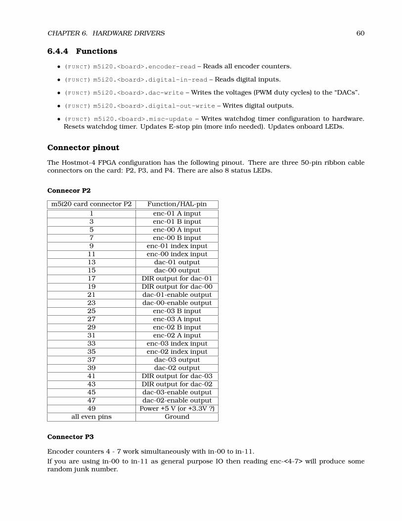
CHAPTER 6. HARDWARE DRIVERS 60
6.4.4 Functions
• (FUNCT) m5i20.<board>.encoder-read – Reads all encoder counters.
• (FUNCT) m5i20.<board>.digital-in-read – Reads digital inputs.
• (FUNCT) m5i20.<board>.dac-write – Writes the voltages (PWM duty cycles) to the “DACs”.
• (FUNCT) m5i20.<board>.digital-out-write – Writes digital outputs.
• (FUNCT) m5i20.<board>.misc-update – Writes watchdog timer configuration to hardware.Resets watchdog timer. Updates E-stop pin (more info needed). Updates onboard LEDs.
Connector pinout
The Hostmot-4 FPGA configuration has the following pinout. There are three 50-pin ribbon cableconnectors on the card: P2, P3, and P4. There are also 8 status LEDs.
Connecor P2
m5i20 card connector P2 Function/HAL-pin1 enc-01 A input3 enc-01 B input5 enc-00 A input7 enc-00 B input9 enc-01 index input11 enc-00 index input13 dac-01 output15 dac-00 output17 DIR output for dac-0119 DIR output for dac-0021 dac-01-enable output23 dac-00-enable output25 enc-03 B input27 enc-03 A input29 enc-02 B input31 enc-02 A input33 enc-03 index input35 enc-02 index input37 dac-03 output39 dac-02 output41 DIR output for dac-0343 DIR output for dac-0245 dac-03-enable output47 dac-02-enable output49 Power +5 V (or +3.3V ?)
all even pins Ground
Connector P3
Encoder counters 4 - 7 work simultaneously with in-00 to in-11.
If you are using in-00 to in-11 as general purpose IO then reading enc-<4-7> will produce somerandom junk number.

CHAPTER 6. HARDWARE DRIVERS 61
m5i20 card connector P3 Function/HAL-pin Secondary Function/HAL-pin1 in-00 enc-04 A input3 in-01 enc-04 B input5 in-02 enc-04 index input7 in-03 enc-05 A input9 in-04 enc-05 B input11 in-05 enc-05 index input13 in-06 enc-06 A input15 in-07 enc-06 B input17 in-08 enc-06 index input19 in-09 enc-07 A input21 in-10 enc-07 B input23 in-11 enc-07 index input25 in-1227 in-1329 in-1431 in-1533 out-0035 out-0137 out-0239 out-0341 out-0443 out-0545 out-0647 out-0749 Power +5 V (or +3.3V ?)
all even pins Ground
Note!: This is the intended pinout of P3. Unfortunately, in the current FPGA configuration dis-tributed with EMC211, the secondary encoders, enc-04, enc-05, enc-06, and enc-07 are wronglyconfigured. The input pins for enc-04 and enc-05 partly overlap, as do the pins for enc-06 andenc-07. Thus it is possible to use enc-04 and enc-06 simultaneously, but using enc-04 and enc-05is not possible since counts on enc-04 will make the count on enc-05 jump by +/- 1. If you areusing pins in-00 to in-11 as general purpose inputs you are not affected by this bug.
Connector P4
The index mask masks the index input of the encoder so that the encoder index can be combinedwith a mechanical switch or opto detector to clear or latch the encoder counter only when themask input bit is in proper state (selected by mask polarity bit) and encoder index occurs. Thisis useful for homing. The behaviour of these pins is controlled by the Counter Control Register(CCR), however there is currently no function in the driver to change the CCR. See REGMAP412 fora description of the CCR.
11emc2/src/hal/drivers/m5i20_HM5-4E.h dated 2005/06/0712emc2/src/hal/drivers/m5i20/REGMAP4E
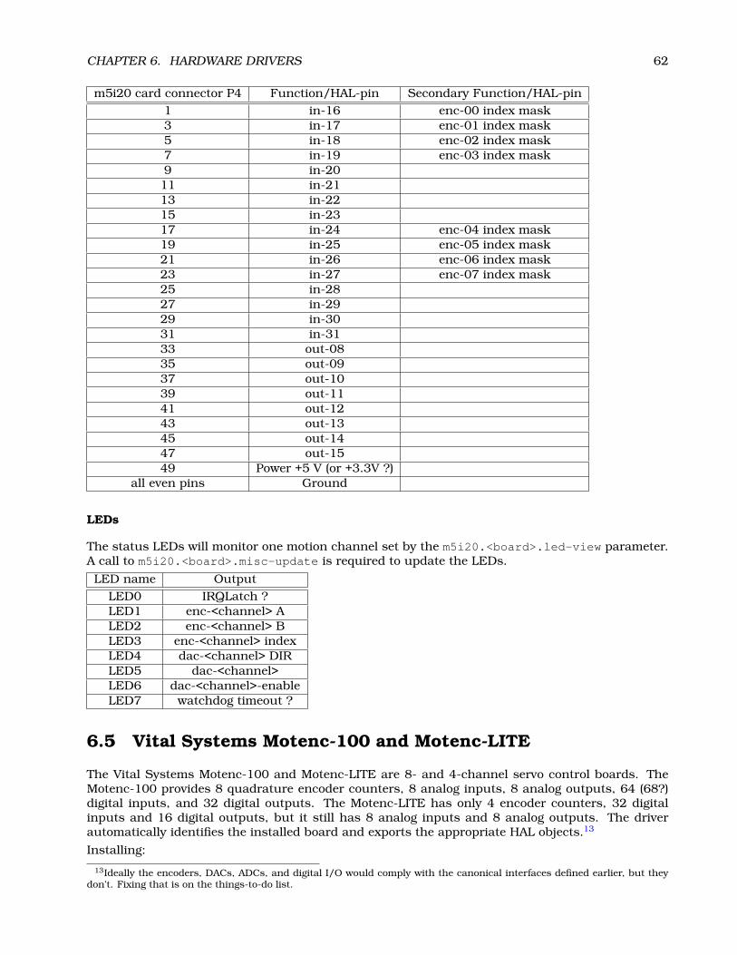
CHAPTER 6. HARDWARE DRIVERS 62
m5i20 card connector P4 Function/HAL-pin Secondary Function/HAL-pin1 in-16 enc-00 index mask3 in-17 enc-01 index mask5 in-18 enc-02 index mask7 in-19 enc-03 index mask9 in-2011 in-2113 in-2215 in-2317 in-24 enc-04 index mask19 in-25 enc-05 index mask21 in-26 enc-06 index mask23 in-27 enc-07 index mask25 in-2827 in-2929 in-3031 in-3133 out-0835 out-0937 out-1039 out-1141 out-1243 out-1345 out-1447 out-1549 Power +5 V (or +3.3V ?)
all even pins Ground
LEDs
The status LEDs will monitor one motion channel set by the m5i20.<board>.led-view parameter.A call to m5i20.<board>.misc-update is required to update the LEDs.
LED name OutputLED0 IRQLatch ?LED1 enc-<channel> ALED2 enc-<channel> BLED3 enc-<channel> indexLED4 dac-<channel> DIRLED5 dac-<channel>LED6 dac-<channel>-enableLED7 watchdog timeout ?
6.5 Vital Systems Motenc-100 and Motenc-LITE
The Vital Systems Motenc-100 and Motenc-LITE are 8- and 4-channel servo control boards. TheMotenc-100 provides 8 quadrature encoder counters, 8 analog inputs, 8 analog outputs, 64 (68?)digital inputs, and 32 digital outputs. The Motenc-LITE has only 4 encoder counters, 32 digitalinputs and 16 digital outputs, but it still has 8 analog inputs and 8 analog outputs. The driverautomatically identifies the installed board and exports the appropriate HAL objects.13
Installing:
13Ideally the encoders, DACs, ADCs, and digital I/O would comply with the canonical interfaces defined earlier, but theydon’t. Fixing that is on the things-to-do list.
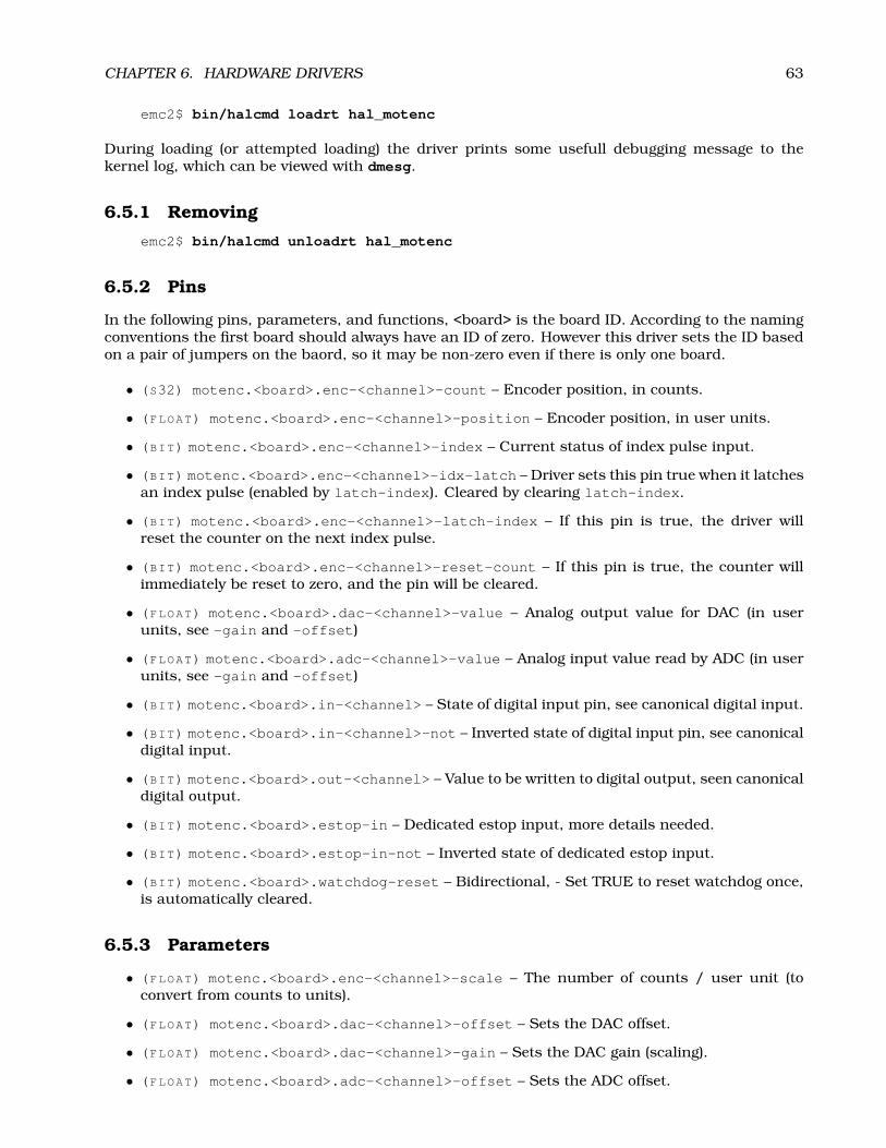
CHAPTER 6. HARDWARE DRIVERS 63
emc2$ bin/halcmd loadrt hal_motenc
During loading (or attempted loading) the driver prints some usefull debugging message to thekernel log, which can be viewed with dmesg.
6.5.1 Removing
emc2$ bin/halcmd unloadrt hal_motenc
6.5.2 Pins
In the following pins, parameters, and functions, <board> is the board ID. According to the namingconventions the first board should always have an ID of zero. However this driver sets the ID basedon a pair of jumpers on the baord, so it may be non-zero even if there is only one board.
• (S32) motenc.<board>.enc-<channel>-count – Encoder position, in counts.
• (FLOAT) motenc.<board>.enc-<channel>-position – Encoder position, in user units.
• (BIT) motenc.<board>.enc-<channel>-index – Current status of index pulse input.
• (BIT) motenc.<board>.enc-<channel>-idx-latch – Driver sets this pin true when it latchesan index pulse (enabled by latch-index). Cleared by clearing latch-index.
• (BIT) motenc.<board>.enc-<channel>-latch-index – If this pin is true, the driver willreset the counter on the next index pulse.
• (BIT) motenc.<board>.enc-<channel>-reset-count – If this pin is true, the counter willimmediately be reset to zero, and the pin will be cleared.
• (FLOAT) motenc.<board>.dac-<channel>-value – Analog output value for DAC (in userunits, see -gain and -offset)
• (FLOAT) motenc.<board>.adc-<channel>-value – Analog input value read by ADC (in userunits, see -gain and -offset)
• (BIT) motenc.<board>.in-<channel> – State of digital input pin, see canonical digital input.
• (BIT) motenc.<board>.in-<channel>-not – Inverted state of digital input pin, see canonicaldigital input.
• (BIT) motenc.<board>.out-<channel> – Value to be written to digital output, seen canonicaldigital output.
• (BIT) motenc.<board>.estop-in – Dedicated estop input, more details needed.
• (BIT) motenc.<board>.estop-in-not – Inverted state of dedicated estop input.
• (BIT) motenc.<board>.watchdog-reset – Bidirectional, - Set TRUE to reset watchdog once,is automatically cleared.
6.5.3 Parameters
• (FLOAT) motenc.<board>.enc-<channel>-scale – The number of counts / user unit (toconvert from counts to units).
• (FLOAT) motenc.<board>.dac-<channel>-offset – Sets the DAC offset.
• (FLOAT) motenc.<board>.dac-<channel>-gain – Sets the DAC gain (scaling).
• (FLOAT) motenc.<board>.adc-<channel>-offset – Sets the ADC offset.

CHAPTER 6. HARDWARE DRIVERS 64
• (FLOAT) motenc.<board>.adc-<channel>-gain – Sets the ADC gain (scaling).
• (BIT) motenc.<board>.out-<channel>-invert – Inverts a digital output, see canonical dig-ital output.
• (U16) motenc.<board>.watchdog-control – Configures the watchdog?
• (U16) motenc.<board>.led-view – Maps some of the I/O to onboard LEDs?
6.5.4 Functions
• (FUNCT) motenc.<board>.encoder-read – Reads all encoder counters.
• (FUNCT) motenc.<board>.adc-read – Reads the analog-to-digital converters.
• (FUNCT) motenc.<board>.digital-in-read – Reads digital inputs.
• (FUNCT) motenc.<board>.dac-write – Writes the voltages to the DACs.
• (FUNCT) motenc.<board>.digital-out-write – Writes digital outputs.
• (FUNCT) motenc.<board>.misc-update – Updates misc stuff.
6.6 Pico Systems PPMC (Parallel Port Motion Control)
Pico Systems has a family of boards for doing servo, stepper, and pwm control. The boards connectto the PC through a parallel port working in EPP mode. Although most users connect one boardto a parallel port, in theory any mix of up to 8 or 16 boards can be used on a single parport. Onedriver serves all types of boards. The final mix of I/O depends on the connected board(s). The driverdoesn’t distinguish between boards, it simply numbers I/O channels (encoders, etc) starting from 0on the first card.
Installing:
emc2$ bin/halcmd loadrt hal_ppmc port_addr=<addr1>[,<addr2>[,<addr3>]]
The port_addr parameter tells the driver what parallel port(s) to check. By default, <addr1> is0x0378, and <addr2> and <addr3> are not used.The driver searches the entire address space ofthe enhanced parallel port(s) at port_addr, looking for any board(s) in the PPMC family. It thenexports HAL pins for whatever it finds. During loading (or attempted loading) the driver prints someusefull debugging message to the kernel log, which can be viewed with dmesg.
6.6.1 Removing
emc2$ bin/halcmd unloadrt hal_ppmc
6.6.2 Pins
In the following pins, parameters, and functions, <board> is the board ID. According to the namingconventions the first board should always have an ID of zero. However this driver sets the ID basedon a pair of jumpers on the baord, so it may be non-zero even if there is only one board.
• (S32) ppmc.<port>.encoder.<channel>.count – Encoder position, in counts.
• (S32) ppmc.<port>.encoder.<channel>.delta – Change in counts since last read.
• (FLOAT) ppmc.<port>.encoder.<channel>.position – Encoder position, in user units.
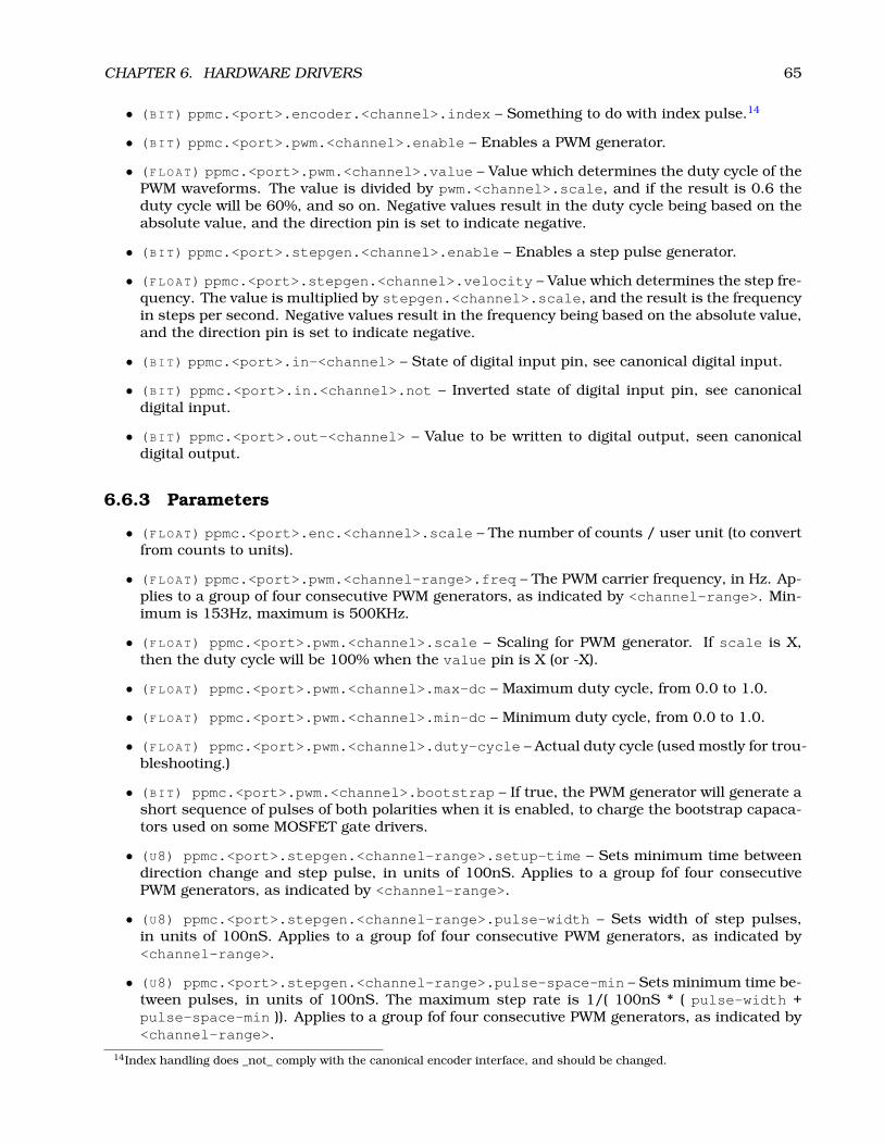
CHAPTER 6. HARDWARE DRIVERS 65
• (BIT) ppmc.<port>.encoder.<channel>.index – Something to do with index pulse.14
• (BIT) ppmc.<port>.pwm.<channel>.enable – Enables a PWM generator.
• (FLOAT) ppmc.<port>.pwm.<channel>.value – Value which determines the duty cycle of thePWM waveforms. The value is divided by pwm.<channel>.scale, and if the result is 0.6 theduty cycle will be 60%, and so on. Negative values result in the duty cycle being based on theabsolute value, and the direction pin is set to indicate negative.
• (BIT) ppmc.<port>.stepgen.<channel>.enable – Enables a step pulse generator.
• (FLOAT) ppmc.<port>.stepgen.<channel>.velocity – Value which determines the step fre-quency. The value is multiplied by stepgen.<channel>.scale, and the result is the frequencyin steps per second. Negative values result in the frequency being based on the absolute value,and the direction pin is set to indicate negative.
• (BIT) ppmc.<port>.in-<channel> – State of digital input pin, see canonical digital input.
• (BIT) ppmc.<port>.in.<channel>.not – Inverted state of digital input pin, see canonicaldigital input.
• (BIT) ppmc.<port>.out-<channel> – Value to be written to digital output, seen canonicaldigital output.
6.6.3 Parameters
• (FLOAT) ppmc.<port>.enc.<channel>.scale – The number of counts / user unit (to convertfrom counts to units).
• (FLOAT) ppmc.<port>.pwm.<channel-range>.freq – The PWM carrier frequency, in Hz. Ap-plies to a group of four consecutive PWM generators, as indicated by <channel-range>. Min-imum is 153Hz, maximum is 500KHz.
• (FLOAT) ppmc.<port>.pwm.<channel>.scale – Scaling for PWM generator. If scale is X,then the duty cycle will be 100% when the value pin is X (or -X).
• (FLOAT) ppmc.<port>.pwm.<channel>.max-dc – Maximum duty cycle, from 0.0 to 1.0.
• (FLOAT) ppmc.<port>.pwm.<channel>.min-dc – Minimum duty cycle, from 0.0 to 1.0.
• (FLOAT) ppmc.<port>.pwm.<channel>.duty-cycle – Actual duty cycle (used mostly for trou-bleshooting.)
• (BIT) ppmc.<port>.pwm.<channel>.bootstrap – If true, the PWM generator will generate ashort sequence of pulses of both polarities when it is enabled, to charge the bootstrap capaca-tors used on some MOSFET gate drivers.
• (U8) ppmc.<port>.stepgen.<channel-range>.setup-time – Sets minimum time betweendirection change and step pulse, in units of 100nS. Applies to a group fof four consecutivePWM generators, as indicated by <channel-range>.
• (U8) ppmc.<port>.stepgen.<channel-range>.pulse-width – Sets width of step pulses,in units of 100nS. Applies to a group fof four consecutive PWM generators, as indicated by<channel-range>.
• (U8) ppmc.<port>.stepgen.<channel-range>.pulse-space-min – Sets minimum time be-tween pulses, in units of 100nS. The maximum step rate is 1/( 100nS * ( pulse-width +pulse-space-min )). Applies to a group fof four consecutive PWM generators, as indicated by<channel-range>.
14Index handling does _not_ comply with the canonical encoder interface, and should be changed.

CHAPTER 6. HARDWARE DRIVERS 66
• (FLOAT) ppmc.<port>.stepgen.<channel>.scale – Scaling for step pulse generator. Thestep frequency in Hz is the absolute value of velocity * scale.
• (FLOAT) ppmc.<port>.stepgen.<channel>.max-vel – The maximum value for velocity.Commands greater than max-vel will be clamped. Also applies to negative values. (The abso-lute value is clamped.)
• (FLOAT) ppmc.<port>.stepgen.<channel>.frequency – Actual step pulse frequency in Hz(used mostly for troubleshooting.)
• (BIT) ppmc.<port>.out.<channel>.invert – Inverts a digital output, see canonical digitaloutput.
6.6.4 Functions
• (FUNCT) ppmc.<port>.read – Reads all inputs (digital inputs and encoder counters) on oneport.
• (FUNCT) ppmc.<port>.write – Writes all outputs (digital outputs, stepgens, PWMs) on oneport.
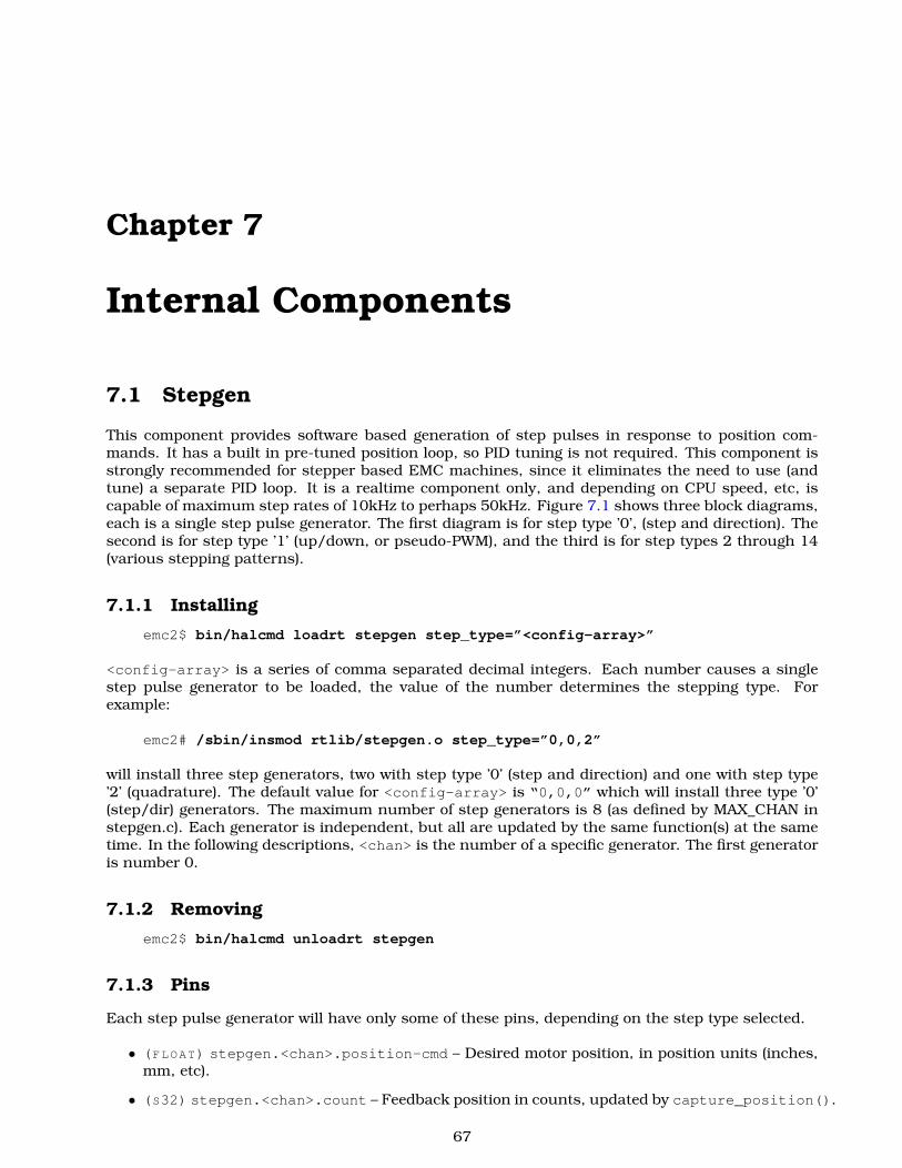
Chapter 7
Internal Components
7.1 Stepgen
This component provides software based generation of step pulses in response to position com-mands. It has a built in pre-tuned position loop, so PID tuning is not required. This component isstrongly recommended for stepper based EMC machines, since it eliminates the need to use (andtune) a separate PID loop. It is a realtime component only, and depending on CPU speed, etc, iscapable of maximum step rates of 10kHz to perhaps 50kHz. Figure 7.1 shows three block diagrams,each is a single step pulse generator. The first diagram is for step type ’0’, (step and direction). Thesecond is for step type ’1’ (up/down, or pseudo-PWM), and the third is for step types 2 through 14(various stepping patterns).
7.1.1 Installing
emc2$ bin/halcmd loadrt stepgen step_type=”<config-array>”
<config-array> is a series of comma separated decimal integers. Each number causes a singlestep pulse generator to be loaded, the value of the number determines the stepping type. Forexample:
emc2# /sbin/insmod rtlib/stepgen.o step_type=”0,0,2”
will install three step generators, two with step type ’0’ (step and direction) and one with step type’2’ (quadrature). The default value for <config-array> is “0,0,0” which will install three type ’0’(step/dir) generators. The maximum number of step generators is 8 (as defined by MAX_CHAN instepgen.c). Each generator is independent, but all are updated by the same function(s) at the sametime. In the following descriptions, <chan> is the number of a specific generator. The first generatoris number 0.
7.1.2 Removing
emc2$ bin/halcmd unloadrt stepgen
7.1.3 Pins
Each step pulse generator will have only some of these pins, depending on the step type selected.
• (FLOAT) stepgen.<chan>.position-cmd – Desired motor position, in position units (inches,mm, etc).
• (S32) stepgen.<chan>.count – Feedback position in counts, updated by capture_position().
67

CHAPTER 7. INTERNAL COMPONENTS 68
position-cmd
position-cmd
position-cmd
phase-B
phase-E
phase-D
down
step
phase-A
phase-C
up
dir
counts
counts
counts
position-fb
position-fb
position-fb
maxaccel
maxaccel
maxaccel
maxfreq
maxfreq
maxfreq
frequencygenerator
frequencygenerator
frequencygenerator
statecounter
lookuptable
ramp
ramp
ramp
latch
latch
latch
counter
counter
counter
step/dirlogicand
timing
vel-err
vel-err
vel-err
pos-err
pos-err
pos-err
frequency
frequency
frequency
stepspace
dirsetup
dirhold
steplen
rawcounts
rawcounts
rawcounts
position-scale
position-scale
position-scale
d
d
d
dT
dT
dT
up/dn
up/dn
up/dn
up/dn
up/dn
up/dn
count
count
count
count
count
count
make_pulses()
make_pulses()
make_pulses()
STEP TYPE = 1
STEP TYPE = 2 - 14
STEP TYPE = 0
update_freq()
update_freq()
update_freq()
capture_position()
capture_position()
capture_position()
stepgen.0
stepgen.0
stepgen.0
1/x
1/x
1/x
1 count
1 count
1 count
controlequation
controlequation
controlequation
Figure 7.1: Step Pulse Generator Block Diagram

CHAPTER 7. INTERNAL COMPONENTS 69
• (FLOAT) stepgen.<chan>.position-fb – Feedback position in position units, updated bycapture_position().
• (BIT) stepgen.<chan>.step – Step pulse output (step type 0 only).
• (BIT) stepgen.<chan>.dir – Direction output (step type 0 only).
• (BIT) stepgen.<chan>.up – UP pseudo-PWM output (step type 1 only).
• (BIT) stepgen.<chan>.down – DOWN pseudo-PWM output (step type 1 only).
• (BIT) stepgen.<chan>.phase-A – Phase A output (step types 2-14 only).
• (BIT) stepgen.<chan>.phase-B – Phase B output (step types 2-14 only).
• (BIT) stepgen.<chan>.phase-C – Phase C output (step types 3-14 only).
• (BIT) stepgen.<chan>.phase-D – Phase D output (step types 5-14 only).
• (BIT) stepgen.<chan>.phase-E – Phase E output (step types 11-14 only).
7.1.4 Parameters
• (FLOAT) stepgen.<chan>.position-scale – Steps per position unit. This parameter is usedfor both output and feedback.
• (FLOAT) stepgen.<chan>.maxfreq – Maximum step rate, in steps per second. If 0.0, has noeffect.
• (FLOAT) stepgen.<chan>.maxaccel – Maximum accel/decel rate, in steps per second squared.If 0.0, has no effect.
• (FLOAT) stepgen.<chan>.pos-err – The position error - difference between commanded andactual position, in steps.
• (FLOAT) stepgen.<chan>.vel-err – The velocity error - in steps per second.
• (FLOAT) stepgen.<chan>.frequency – The current step rate, in steps per second. This is theoutput of the position loop.
• (FLOAT) stepgen.<chan>.steplen – Length of a step pulse (step type 0 only).
• (FLOAT) stepgen.<chan>.stepspace – Minimum spacing between two step pulses (step type0 only).
• (FLOAT) stepgen.<chan>.dirsetup – Minimum time from a direction change to the begin-ning of the next step pulse (step type 0 only).
• (FLOAT) stepgen.<chan>.dirhold – Minmum time from the end of a step pulse to a directionchange (step type 0 only).
• (S32) stepgen.<chan>.rawcounts – The raw feedback count, updated by make_pulses().
The values of maxfreq and maxaccel are used by the internal position loop to avoid generating steppulse trains that the motor cannot follow. When set to values that are appropriate for the motor,even a large instantaneous change in commanded position will result in a smooth trapezoidal moveto the new location. The algorithm works by measuring both position error and velocity error, andcalculating an acceleration that attempts to reduce both to zero at the same time. For more details,including the contents of the “control equation” box, consult the code.

CHAPTER 7. INTERNAL COMPONENTS 70
7.1.5 Step Types
The step generator supports 15 different “step types”. Step type 0 is the most familiar, standard stepand direction. When configured for step type 0, there are four extra parameters that determine theexact timing of the step and direction signals. See figure 7.2 for the meaning of these parameters.The parameters are integers, and represent a number of calls to make_pulses(). For example,if make_pulses() is called every 16uS, and steplen is 2, then the step pulses will be 2 x 16 =32uS long. The default value for all four of the parameters is 1. Since one step requires steplenperiods high and stepspace periods low, the maximum frequency is the thread frequency dividedby (steplen+stepspace). If maxfreq is set higher than that limit, it will be lowered automatically.If maxfreq is zero, it will remain zero, but the output frequency will still be limited.
step lenstep len s tepspace(min)
s tepspace(min)
di rsetup(min)
di rsetup(min)
dirhold(min)
s tep len
step
direct ion
Figure 7.2: Step and Direction Timing
Step type 1 has two outputs, up and down. Pulses appear on one or the other, depending on thedirection of travel. Each pulse is one thread period long, and the pulses are separated by at leastone thread period. As a result, the maximum step frequency is half of the thread rate. If maxfreqis set higher than the limit it will be lowered. If maxfreq is zero, it will remain zero but the outputfrequency will still be limited.Step types 2 through 14 are state based, and have from two to five outputs. On each step, a statecounter is incremented or decremented. Figures 7.3, 7.4, and 7.5 show the output patterns as afunction of the state counter. The maximum frequency is the same as the thread rate, and as in theother modes, maxfreq will be lowered if it is above the limit.
7.1.6 Functions
The component exports three functions. Each function acts on all of the step pulse generators -running different generators in different threads is not supported.
• (FUNCT) stepgen.make-pulses – High speed function to generate and count pulses (no float-ing point).
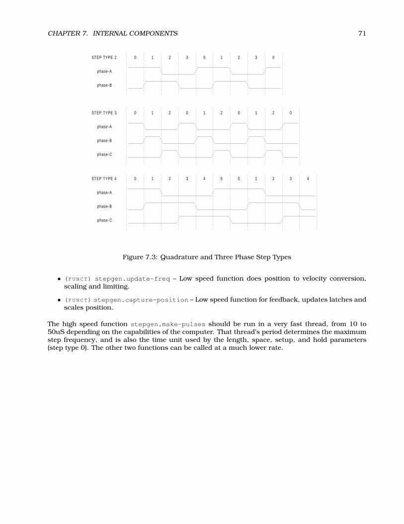
CHAPTER 7. INTERNAL COMPONENTS 71
0
0
0
1
1
1
2
2
2
1
4
0
0
3
3
2
5
1
0
0
2
1
1
3
2
2
0
0
3 4
STEP TYPE 3
STEP TYPE 4
STEP TYPE 2
phase-A
phase-A
phase-A
phase-B
phase-B
phase-B
phase-C
phase-C
Figure 7.3: Quadrature and Three Phase Step Types
• (FUNCT) stepgen.update-freq – Low speed function does position to velocity conversion,scaling and limiting.
• (FUNCT) stepgen.capture-position – Low speed function for feedback, updates latches andscales position.
The high speed function stepgen.make-pulses should be run in a very fast thread, from 10 to50uS depending on the capabilities of the computer. That thread’s period determines the maximumstep frequency, and is also the time unit used by the length, space, setup, and hold parameters(step type 0). The other two functions can be called at a much lower rate.
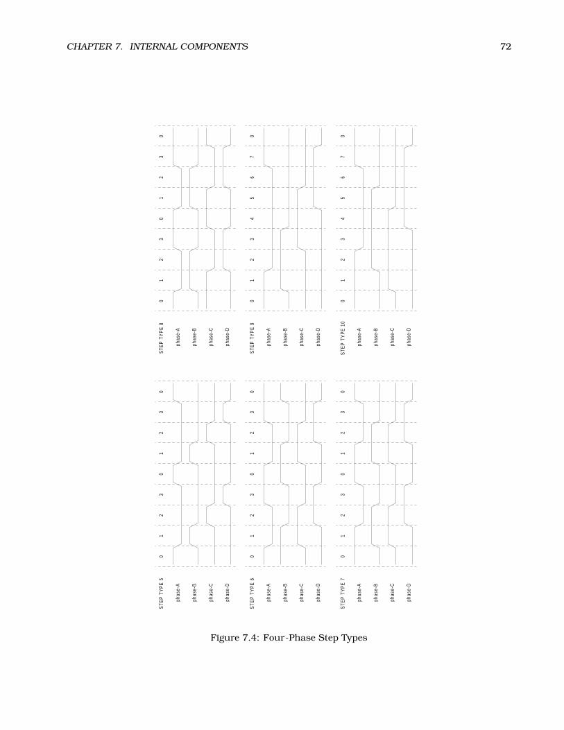
CHAPTER 7. INTERNAL COMPONENTS 72
0 0
00
0 0
1 1
11
1 1
2 2
22
2 2
0 0
00
4 4
3 3
33
3 3
1 1
11
5 5
2 2
22
6 6
3 3
33
7 7
0 0
00
0 0
STE
P T
YP
E 5
STE
P T
YP
E 6
STE
P T
YP
E 7
STE
P T
YP
E 8
STE
P T
YP
E 9
STE
P T
YP
E 1
0
phas
e-A
phas
e-A
phas
e-A
phas
e-A
phas
e-A
phas
e-A
phas
e-B
phas
e-B
phas
e-B
phas
e-B
phas
e-B
phas
e-B
phas
e-C
phas
e-C
phas
e-C
phas
e-C
phas
e-C
phas
e-C
phas
e-D
phas
e-D
phas
e-D
phas
e-D
phas
e-D
phas
e-D
Figure 7.4: Four-Phase Step Types

CHAPTER 7. INTERNAL COMPONENTS 73
0
0
0
0
0
0
1
1
1
1
1
1
2
2
2
2
2
2
4
4
4
4
4
4
3
3
3
3
3
3
5
5
6
6
7
7
8
8
9
9
0
0
0
0
STEP TYPE 11
STEP TYPE 12
STEP TYPE 14
STEP TYPE 13
phase-A
phase-A
phase-A
phase-A
phase-B
phase-B
phase-B
phase-B
phase-C
phase-C
phase-C
phase-C
phase-D
phase-D
phase-D
phase-D
phase-E
phase-E
phase-E
phase-E
Figure 7.5: Five-Phase Step Types

CHAPTER 7. INTERNAL COMPONENTS 74
7.2 Freqgen
This component provides software based generation of step pulses from a frequency or velocitycommand. EMC normally uses position commands, not velocity commands, and stepgen (describedin section 7.1 is more appropriate. However, there may be applications where velocity based pulsesare needed. One such application is using step type 1 as a pseudo-PWM output. Combined witha PID loop. the software encoder counter module, and a simple H-bridge, this has been used torun small DC servomotors. Freqgen uses the same pulse generator core as stepgen, however it hasno position loop. It is a realtime component only, and depending on CPU speed, etc, is capable ofmaximum step rates of 10kHz to perhaps 50kHz. Figure 7.6 shows three block diagrams, each is asingle step pulse generator. The first diagram is for step type ’0’, (step and direction). The secondis for step type ’1’ (up/down, or pseudo-PWM), and the third is for step types 2 through 14 (variousstepping patterns).
7.2.1 Installing
emc2$ bin/halcmd loadrt freqgen step_type=”<config-array>”
<config-array> is a series of comma separated decimal integers. Each number causes a sin-gle frequency generator to be loaded, the value of the number determines the stepping type. Forexample:
emc2$ bin/halcmd loadrt freqgen step_type=”0,0,2”
will install three frequency generators, two with step type ’0’ (step and direction) and one withstep type ’2’ (quadrature). The default value for <config-array> is “0,0,0” which will installthree type ’0’ (step/dir) generators. The maximum number of frequency generators is 8 (as definedby MAX_CHAN in freqgen.c). Each generator is independent, but all are updated by the samefunction(s) at the same time. In the following descriptions, <chan> is the number of a specificgenerator. The first generator is number 0.
7.2.2 Removing
emc2$ bin/halcmd unloadrt freqgen
7.2.3 Pins
Each frequency generator will have only some of these pins, depending on the step type selected.
• (BIT) freqgen.<chan>.velocity – Desired velocity, in arbitrary units.
• (BIT) freqgen.<chan>.step – Step pulse output (step type 0 only).
• (BIT) freqgen.<chan>.dir – Direction output (step type 0 only).
• (BIT) freqgen.<chan>.up – UP pseudo-PWM output (step type 1 only).
• (BIT) freqgen.<chan>.down – DOWN pseudo-PWM output (step type 1 only).
• (BIT) freqgen.<chan>.phase-A – Phase A output (step types 2-14 only).
• (BIT) freqgen.<chan>.phase-B – Phase B output (step types 2-14 only).
• (BIT) freqgen.<chan>.phase-C – Phase C output (step types 3-14 only).
• (BIT) freqgen.<chan>.phase-D – Phase D output (step types 5-14 only).
• (BIT) freqgen.<chan>.phase-E – Phase E output (step types 11-14 only).
• (S32) freqgen.<chan>.count – Feedback position in counts, updated by capture_position().
• (FLOAT) freqgen.<chan>.position-fb – Position feedback in arbitrary units updated bycapture_position().
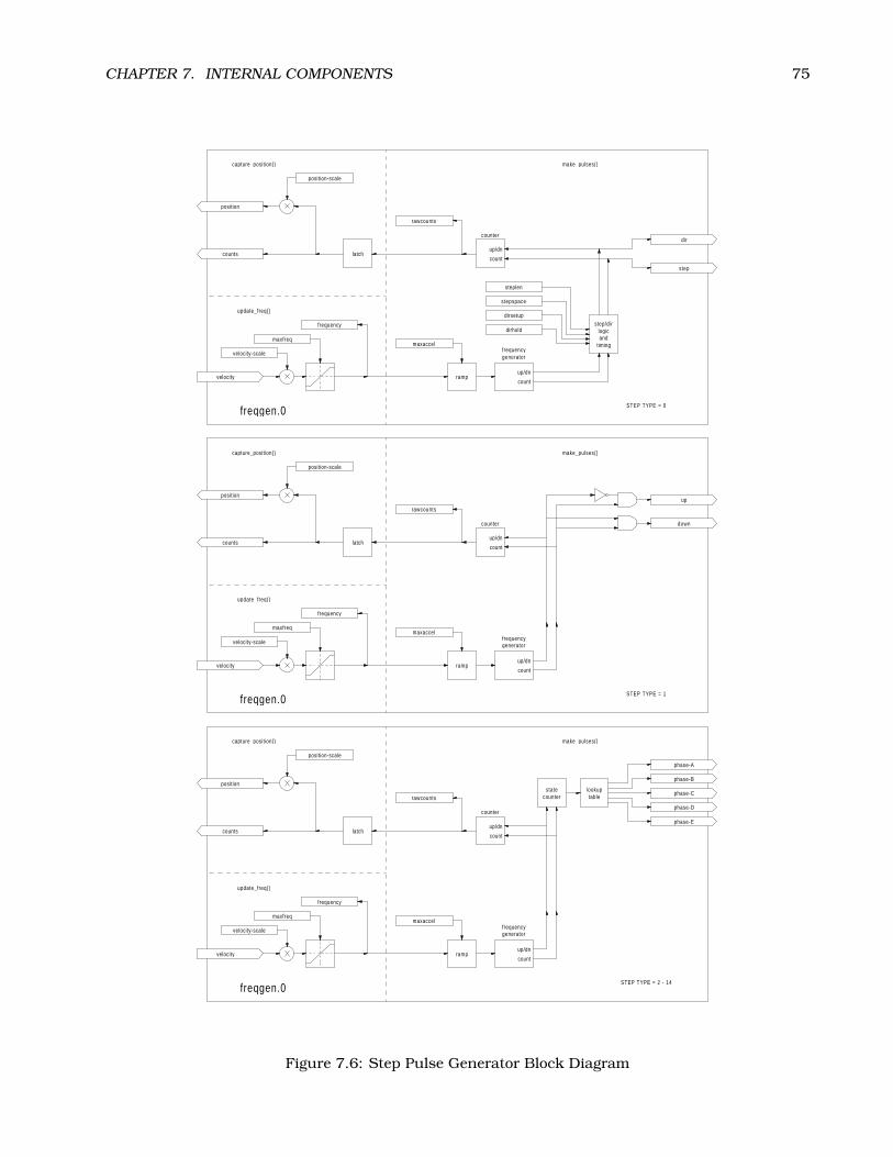
CHAPTER 7. INTERNAL COMPONENTS 75
velocity
velocity
velocity
phase-B
phase-E
phase-D
down
step
phase-A
phase-C
up
dir
counts
counts
counts
position
position
position
maxfreq
maxfreq
maxfreq
frequencygenerator
frequencygenerator
frequencygenerator
statecounter
lookuptable
ramp
ramp
ramp
latch
latch
latch
counter
counter
counter
step/dirlogicand
timing
maxaccel
maxaccel
maxaccel
frequency
frequency
frequency
stepspace
dirsetup
dirhold
steplen
rawcounts
rawcounts
rawcounts
velocity-scale
velocity-scale
velocity-scale
position-scale
position-scale
position-scale
up/dn
up/dn
up/dn
up/dn
up/dn
up/dn
count
count
count
count
count
count
make_pulses()
make_pulses()
STEP TYPE = 1
STEP TYPE = 2 - 14
STEP TYPE = 0
make_pulses()
update_freq()
update_freq()
update_freq()
capture_position()
capture_position()
capture_position()
freqgen.0
freqgen.0
freqgen.0
Figure 7.6: Step Pulse Generator Block Diagram
CHAPTER 7. INTERNAL COMPONENTS 76
7.2.4 Parameters
• (FLOAT) freqgen.<chan>.velocity-scale – Scaling factor to convert from velocity units topulses per second (Hz).
• (FLOAT) freqgen.<chan>.maxfreq – Maximum frequency, in Hz. If 0.0, has no effect. If sethigher than internal limits, next call of update_freq() will set it to the internal limit.
• (FLOAT) freqgen.<chan>.frequency – The current frequency, in Hz. This is the value afterscaling and limiting.
• (FLOAT) freqgen.<chan>.maxaccel – Maximum accel/decel rate, in Hz per second. If 0.0,has no effect.
• (FLOAT) freqgen.<chan>.steplen – Length of a step pulse (step type 0 only).
• (FLOAT) freqgen.<chan>.stepspace – Minimum spacing between two step pulses (step type0 only).
• (FLOAT) freqgen.<chan>.dirsetup – Minimum time from a direction change to the begin-ning of the next step pulse (step type 0 only).
• (FLOAT) freqgen.<chan>.dirhold – Minmum time from the end of a step pulse to a directionchange (step type 0 only).
• (S32) freqgen.<chan>.rawcounts – The raw feedback count, updated by make_pulses().
• (FLOAT) freqgen.<chan>.position-scale – The scale factor used to convert from feedbackcounts to position units.
7.2.5 Step Types
The frequency generator supports 15 different “step types”. Except for stepping type 1, they areidentical to those generated by the stepgen component. Refer to section 7.1.5 for more information.There is one difference between stepgen and freqgen. Step type 1 has two outputs, up and down.Pulses appear on one or the other, depending on the direction of travel. Each pulse is one threadperiod long. Stepgen assumes that you need a distinct pulse for each step, so it limits the frequencyto half of the thread rate, to allow for one low period between pulses. However, freqgen allows higherfrequencies, up to the thread rate. This allows step type 1 to be used as a pseudo-PWM source, orfiltered to use as a D-to-A converter. At the maximum frequency (equal to the thread rate), the upor down output will remain on constantly.
7.2.6 Functions
The component exports three functions. Each function acts on all of the step pulse generators -running different generators in different threads is not supported.
• (FUNCT) freqgen.make-pulses – High speed function to generate and count pulses (no float-ing point).
• (FUNCT) freqgen.update-freq – Low speed function to scale and limit velocity command.
• (FUNCT) freqgen.capture-position – Low speed function for feedback, updates latches andscales position.
The high speed function freqgen.make-pulses should be run in a very fast thread, from 10 to50uS depending on the capabilities of the computer. That thread’s period determines the maximumstep frequency, and is also the time unit used by the length, space, setup, and hold parameters(step type 0). The other two functions can be called at a much lower rate.

CHAPTER 7. INTERNAL COMPONENTS 77
7.3 Encoder
This component provides software based counting of signals from quadrature encoders. It is arealtime component only, and depending on CPU speed, etc, is capable of maximum count rates of10kHz to perhaps 50kHz. Figure 7.7 is a block diagram of one channel of encoder counter.
reset
index-enable phase-Z
phase-B
phase-A
counts
position
latch
counter
edgedetect
quaddecode
rawcounts
position-scale
up/dn
count
clear
update-counters()capture-position()
encoder.0
Figure 7.7: Encoder Counter Block Diagram
7.3.1 Installing
emc2$ bin/halcmd loadrt encoder [num_chan=<counters>]
<counters> is the number of encoder counters that you want to install. If numchan is not specified,three counters will be installed. The maximum number of counters is 8 (as defined by MAX_CHANin encoder.c). Each counter is independent, but all are updated by the same function(s) at the sametime. In the following descriptions, <chan> is the number of a specific counter. The first counter isnumber 0.
7.3.2 Removing
emc2$ bin/halcmd unloadrt encoder
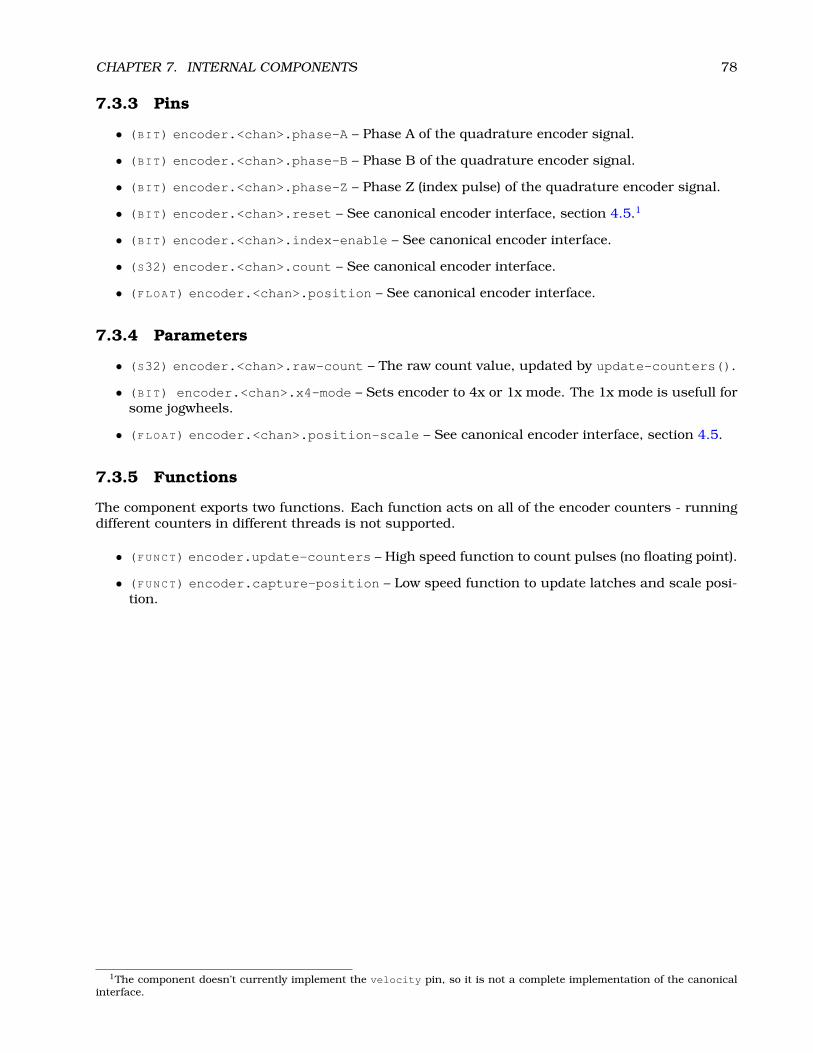
CHAPTER 7. INTERNAL COMPONENTS 78
7.3.3 Pins
• (BIT) encoder.<chan>.phase-A – Phase A of the quadrature encoder signal.
• (BIT) encoder.<chan>.phase-B – Phase B of the quadrature encoder signal.
• (BIT) encoder.<chan>.phase-Z – Phase Z (index pulse) of the quadrature encoder signal.
• (BIT) encoder.<chan>.reset – See canonical encoder interface, section 4.5.1
• (BIT) encoder.<chan>.index-enable – See canonical encoder interface.
• (S32) encoder.<chan>.count – See canonical encoder interface.
• (FLOAT) encoder.<chan>.position – See canonical encoder interface.
7.3.4 Parameters
• (S32) encoder.<chan>.raw-count – The raw count value, updated by update-counters().
• (BIT) encoder.<chan>.x4-mode – Sets encoder to 4x or 1x mode. The 1x mode is usefull forsome jogwheels.
• (FLOAT) encoder.<chan>.position-scale – See canonical encoder interface, section 4.5.
7.3.5 Functions
The component exports two functions. Each function acts on all of the encoder counters - runningdifferent counters in different threads is not supported.
• (FUNCT) encoder.update-counters – High speed function to count pulses (no floating point).
• (FUNCT) encoder.capture-position – Low speed function to update latches and scale posi-tion.
1The component doesn’t currently implement the velocity pin, so it is not a complete implementation of the canonicalinterface.

CHAPTER 7. INTERNAL COMPONENTS 79
7.4 PID
This component provides Proportional/Integeral/Derivative control loops. It is a realtime compo-nent only. For simplicity, this discussion assumes that we are talking about position loops, howeverthis component can be used to implement other feedback loops such as speed, torch height, tem-perature, etc. Figure 7.8 is a block diagram of a single PID loop.
7.4.1 Installing
emc2$ bin/halcmd loadrt pid [num_chan=<loops>] [debug=1] [fp_period=<nsec>]
<loops> is the number of PID loops that you want to install. If numchan is not specified, one loopwill be installed. The maximum number of loops is 16 (as defined by MAX_CHAN in pid.c). Eachloop is completely independent. In the following descriptions, <loopnum> is the loop number of aspecific loop. The first loop is number 0.
If debug=1 is specified, the component will export a few extra parameters that may be useful duringdebugging and tuning. By default, the extra parameters are not exported, to save shared memoryspace and avoid cluttering the parameter list.
If fp_period is specified, the component will create a realtime thread, capable of running floatingpoint functions. The period of the thread will be <nsec> nano-seconds. By default, no thread iscreated.
7.4.2 Removing
emc2$ bin/halcmd unloadrt pid
7.4.3 Pins
The three most important pins are
• (FLOAT) pid.<loopnum>.command – The desired position, as commanded by another systemcomponent.
• (FLOAT) pid.<loopnum>.feedback – The present position, as measured by a feedback devicesuch as an encoder.
• (FLOAT) pid.<loopnum>.output – A velocity command that attempts to move from the presentposition to the desired position.
For a position loop, ’command’ and ’feedback’ are in position units. For a linear axis, this couldbe inches, mm, meters, or whatever is relevant. Likewise, for an angular axis, it could be degrees,radians, etc. The units of the ’output’ pin represent the change needed to make the feedbackmatch the command. As such, for a position loop ’Output’ is a velocity, in inches/sec, mm/sec,degrees/sec, etc. Time units are always seconds, and the velocity units match the position units. Ifcommand and feedback are in meters, then output is in meters per second.
Each loop has two other pins which are used to monitor or control the general operation of thecomponent.
• (FLOAT) pid.<loopnum>.error – Equals .command minus .feedback.
• (BIT) pid.<loopnum>.enable – A bit that enables the loop. If .enable is false, all integratorsare reset, and the output is forced to zero. If .enable is true, the loop operates normally.
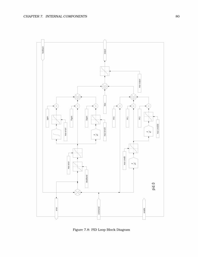
CHAPTER 7. INTERNAL COMPONENTS 80
outp
ut
enab
le
com
man
d
feed
back
erro
r
max
-cm
dDD
max
-cm
dD
max
-err
orD
Pgai
n
FF2
bias
FF0
FF1
Dga
in
Igai
n
max
-err
orI
max
-out
put
max
-err
or
dead
band
pid.
0
d
d
d
dT
dT
dT
Figure 7.8: PID Loop Block Diagram

CHAPTER 7. INTERNAL COMPONENTS 81
7.4.4 Parameters
The PID gains, limits, and other ’tunable’ features of the loop are implemented as parameters.
• (FLOAT) pid.<loopnum>.Pgain – Proportional gain
• (FLOAT) pid.<loopnum>.Igain – Integral gain
• (FLOAT) pid.<loopnum>.Dgain – Derivative gain
• (FLOAT) pid.<loopnum>.bias – Constant offset on output
• (FLOAT) pid.<loopnum>.FF0 – Zeroth order feedforward - output proportional to command(position).
• (FLOAT) pid.<loopnum>.FF1 – First order feedforward - output proportional to derivative ofcommand (velocity).
• (FLOAT) pid.<loopnum>.FF2 – Second order feedforward - output proportional to 2nd deriva-tive of command (acceleration)2.
• (FLOAT) pid.<loopnum>.deadband – Amount of error that will be ignored
• (FLOAT) pid.<loopnum>.maxerror – Limit on error
• (FLOAT) pid.<loopnum>.maxerrorI – Limit on error integrator
• (FLOAT) pid.<loopnum>.maxerrorD – Limit on error derivative
• (FLOAT) pid.<loopnum>.maxcmdD – Limit on command derivative
• (FLOAT) pid.<loopnum>.maxcmdDD – Limit on command 2nd derivative
• (FLOAT) pid.<loopnum>.maxoutput – Limit on output value
All of the max??? limits are implemented such that if the parameter value is zero, there is no limit.
If debug=1 was specified when the component was installed, four additional parameters will beexported:
• (FLOAT) pid.<loopnum>.errorI – Integral of error.
• (FLOAT) pid.<loopnum>.errorD – Derivative of error.
• (FLOAT) pid.<loopnum>.commandD – Derivative of the command.
• (FLOAT) pid.<loopnum>.commandDD – 2nd derivative of the command.
7.4.5 Functions
The component exports one function for each PID loop. This function performs all the calculationsneeded for the loop. Since each loop has it’s own function, individual loops can be included indifferent threads and execute at different rates.
• (FUNCT) pid.<loopnum>.do_pid_calcs – Performs all calculations for a single PID loop.
If you want to understand the exact algorithm used to compute the output of the PID loop, refer tofigure 7.8, the comments at the beginning of emc2/src/hal/components/pid.c, and of course tothe code itself. The loop calculations are in the C function calc_pid().
2FF2 is not currently implemented, but it will be added. Consider this note a “FIXME” for the code
CHAPTER 7. INTERNAL COMPONENTS 82
7.5 Simulated Encoder
The simulated encoder is exactly that. It produces quadrature pulses with an index pulse, at aspeed controlled by a HAL pin. Mostly useful for testing.
7.5.1 Installing
emc2$ bin/halcmd loadrt sim-encoder num_chan=<number>
<number> is the number of encoders that you want to simulate. If not specified, one encoder will beinstalled. The maximum number is 8 (as defined by MAX_CHAN in sim_encoder.c).
7.5.2 Removing
emc2$ bin/halcmd unloadrt sim-encoder
7.5.3 Pins
• (FLOAT) sim-encoder.<chan-num>.speed – The speed command for the simulated shaft.
• (BIT) sim-encoder.<chan-num>.phase-A – Quadrature output.
• (BIT) sim-encoder.<chan-num>.phase-B – Quadrature output.
• (BIT) sim-encoder.<chan-num>.phase-Z – Index pulse output.
When .speed is positive, .phase-A leads .phase-B.
7.5.4 Parameters
• (U32) sim-encoder.<chan-num>.ppr – Pulses Per Revolution.
• (FLOAT) sim-encoder.<chan-num>.scale – Scale Factor for speed. The default is 1.0, whichmeans that speed is in revolutions per second. Change to 60 for RPM, to 360 for degrees persecond, 6.283185 for radians per seconed, etc.
Note that pulses per revolution is not the same as counts per revolution. A pulse is a completequadrature cycle. Most encoder counters will count four times during one complete cycle.
7.5.5 Functions
The component exports two functions. Each function affects all simulated encoders.
• (FUNCT) sim-encoder.make-pulses – High speed function to generate quadrature pulses (nofloating point).
• (FUNCT) sim-encoder.update-speed – Low speed function to read speed, do scaling, and setup make-pulses.

CHAPTER 7. INTERNAL COMPONENTS 83
7.6 Debounce
Debounce is a realtime component that can filter the glitches created by mechanical switch contacts.It may also be useful in other applications where short pulses are to be rejected.
7.6.1 Installing
emc2$ bin/halcmd loadrt debounce cfg=”<config-string>”
<config-string> is a series of space separated decimal integers. Each number installs a group ofidentical debounce filters, the number determines how many filters are in the group. For example:
emc2$ bin/halcmd loadrt debounce cfg=”1 4 2”
will install three groups of filters. Group 0 contains one filter, group 1 contains four, and group2 contains two filters. The default value for <config-string> is “1” which will install a singlegroup containing a single filter. The maximum number of groups 8 (as defined by MAX_GROUPS indebounce.c). The maximum number of filters in a group is limited only by shared memory space.Each group is completely independent. All filters in a single group are identical, and they are allupdated by the same function at the same time. In the following descriptions, <G> is the groupnumber and <F> is the filter number within the group. The first filter is group 0, filter 0.
7.6.2 Removing
emc2$ bin/halcmd unloadrt debounce
7.6.3 Pins
Each individual filter has two pins.
• (BIT) debounce.<G>.<F>.in – Input of filter <F> in group <G>.
• (BIT) debounce.<G>.<F>.out – Output of filter <F> in group <G>.
7.6.4 Parameters
Each group of filters has one parameter3.
• (S32) debounce.<G>.delay – Filter delay for all filters in group <G>.
The filter delay is in units of thread periods. The minimum delay is zero. The output of a zero delayfilter exactly follows it’s input - it doesn’t filter anything. As delay increases, longer and longerglitches are rejected. If delay is 4, all glitches less than or equal to four thread periods will berejected.
7.6.5 Functions
Each group of filters has one function, which updates all the filters in that group “simultaneously”.Different groups of filters can be updated from different threads at different periods.
• (FUNCT) debounce.<G> – Updates all filters in group <G>.
3Each individual filter also has an internal state variable. There is a compile time switch that can export that variable asa parameter. This is intended for testing, and simply wastes shared memory under normal circumstances.
CHAPTER 7. INTERNAL COMPONENTS 84
7.7 Blocks
Blocks is a realtime HAL component containing a number of simple functional blocks. They areprimarily intended for testing and other offhand uses, but may prove useful for some EMC configu-rations as well.
7.7.1 Available Blocks
The complete list of available blocks is as follows:
• constant – makes a parameter value available on a pin
• comp – standard 2-input comparator with adjustable hysteresis
• wcomp – window comparator, output true when input is between adjustable upper and lowerlimits
• sum2 – 2-input summer, output = in0 * gain0 + in1 * gain1
• mux2 – 2-input multiplexor, output = in0 if sel is false, output = in1 if sel is true
• mux4 – 4-input multiplexor, output = in<n> based on sel0, sel1
• integ – integrator, input of +1.0 produces an output ramp of +1.0 per second
• ddt – differentiator, input ramp of +1.0 per second produces output of +1.0
• limit1 – first order limiter (limits output)
• limit2 – second order limiter (limits output and 1st derivative)
• limit3 – third order limiter (limits ouput, 1st & 2nd derivative)
• estop – latch for estops or other faults, with reset
• not – logical inverter
• and2 – 2 input logical and
• or2 – 2 input logical or
• scale – gain/offset block (out = in * gain + offset)
• lowpass – lowpass filter (out = last_out * (1 - gain) + in * gain
• match8 – 8 bit binary match detector (with input for cascading)
7.7.2 Installing
emc2$ bin/halcmd loadrt blocks <blockname>=<number>
<blockname> is the name of one of the functional blocks that the component can provide, and<number> is the desired quantity of that block. Multiple name/number pairs may be specified onthe command line to install a variety of different blocks. For example:
emc2$ bin/halcmd loadrt blocks wcomp=2 sum2=1 comp=3
installs two window comparators (wcomp), one two-input summer (sum2), and three standard com-parators (comp).

CHAPTER 7. INTERNAL COMPONENTS 85
7.7.3 Removing
emc2$ bin/halcmd unloadrt blocks
7.7.4 Pins
The various blocks each have their own input and output pins. Each pin begins with the blockname, then the block number, and finally the pin function.
• (FLOAT) constant.<num>.out – Output of constant block, tracks the parameter value.
• (FLOAT) comp.<num>.in0 – Inverting input of 2-input comparator.
• (FLOAT) comp.<num>.in1 – Non-inverting input of 2-input comparator.
• (BIT) comp.<num>.out – Output, true if in1 > in0.
• (FLOAT) wcomp.<num>.in –Input of window comparator.
• (BIT) wcomp.<num>.out – Output, TRUE if min < input < max.
• (FLOAT) sum2.<num>.in0 – First input of 2-input summer.
• (FLOAT) sum2.<num>.in1 – Second input of 2-input summer.
• (FLOAT) sum2.<num>.out – Output, equals in0 * gain0 + in1 * gain1.
• (FLOAT) mux2.<num>.in0 – First input of 2-input multiplexor.
• (FLOAT) mux2.<num>.in1 –Second input of 2-input multiplexor.
• (BIT) mux2.<num>.sel – Control input of 2-input multiplexor.
• (FLOAT) mux2.<num>.out – Output, equals in0 if sel is FALSE, in1 if sel is TRUE.
• (FLOAT) integ.<num>.in – Input of integrator.
• (FLOAT) integ.<num>.out – Output of integrator.
• (FLOAT) ddt.<num>.in – Input of differentiator.
• (FLOAT) ddt.<num>.out – Output of differentiator.
• ... and so on (too many pins to list them all here, but you can easily see them with halcmdshow pin )
7.7.5 Parameters
Some of the blocks have parameters that control and adjust the details of their operation. Like thepin names, they begin with the block name and the block number, then the parameter name.
• (FLOAT) constant.<num>.value – The value to be written to the out pin, default value is 1.0.
• (FLOAT) comp.<num>.hyst – Hystersis for 2-input comparator, default is 0.0.
• (FLOAT) wcomp.<num>.min – Minimum threshold for window comparator, default is -1.0.
• (FLOAT) wcomp.<num>.max – Maximum threshold for window comparator, default is +1.0.
• (FLOAT) sum2.<num>.gain0 – Value by which in0 is multiplied, default is 1.0.
• (FLOAT) sum2.<num>.gain1 – Value by which in1 is multiplied, default is 1.0.
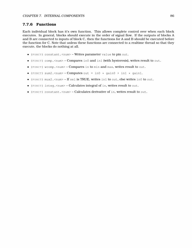
CHAPTER 7. INTERNAL COMPONENTS 86
7.7.6 Functions
Each individual block has it’s own function. This allows complete control over when each blockexecutes. In general, blocks should execute in the order of signal flow. If the outputs of blocks Aand B are connected to inputs of block C, then the functions for A and B should be executed beforethe function for C. Note that unless these functions are connected to a realtime thread so that theyexecute, the blocks do nothing at all.
• (FUNCT) constant.<num> – Writes parameter value to pin out.
• (FUNCT) comp.<num> – Compares in0 and in1 (with hysteresis), writes result to out.
• (FUNCT) wcomp.<num> – Compares in to min and max, writes result to out.
• (FUNCT) sum2.<num> – Computes out = in0 * gain0 + in1 * gain1.
• (FUNCT) mux2.<num> – If sel is TRUE, writes in1 to out, else writes in0 to out.
• (FUNCT) integ.<num> – Calculates integral of in, writes result to out.
• (FUNCT) constant.<num> – Calculates derivative of in, writes result to out.

CHAPTER 7. INTERNAL COMPONENTS 87
7.8 Siggen
Siggen is a realtime component that generates square, triangle, and sine waves. It is primarily usedfor testing.
7.8.1 Installing
emc2$ bin/halcmd loadrt siggen [num_chan=<chans>] [fp_period=<nsec>]
<chans> is the number of signal generators that you want to install. If numchan is not specified,one signal generator will be installed. The maximum number of generators is 16 (as defined byMAX_CHAN in siggen.c). Each generator is completely independent. In the following descriptions,<chan> is the number of a specific signal generator (the numbers start at 0).If fp_period is specified, the component will create a realtime thread, capable of running floatingpoint functions. The period of the thread will be <nsec> nano-seconds. By default, no thread iscreated.
7.8.2 Removing
emc2$ bin/halcmd unloadrt siggen
7.8.3 Pins
Each generator has four output pins.
• (FLOAT) siggen.<chan>.sine – Sine wave output.
• (FLOAT) siggen.<chan>.cosine – Cosine output.
• (FLOAT) siggen.<chan>.sawtooth – Sawtooth output.
• (FLOAT) siggen.<chan>.triangle – Triangle wave output.
• (FLOAT) siggen.<chan>.square – Square wave output.
All five outputs have the same frequency, amplitude, and offset.
7.8.4 Parameters
Each generator is controlled by three parameters.
• (FLOAT) siggen.<chan>.frequency – Sets the frequency in Hertz, default value is 1 Hz.
• (FLOAT) siggen.<chan>.amplitude – Sets the peak amplitude of the output waveforms, de-fault is 1.
• (FLOAT) siggen.<chan>.offset – Sets DC offset of the output waveforms, default is 0.
For example, if siggen.0.amplitude is 1.0 and siggen.0.offset is 0.0, the outputs will swingfrom -1.0 to +1.0. If siggen.0.amplitude is 2.5 and siggen.0.offset is 10.0, then the outputswill swing from 7.5 to 12.5.
7.8.5 Functions
• (FUNCT) siggen.<chan>.update – Calculates new values for all five outputs.

Chapter 8
Halui
8.1 Introduction
Halui is a HAL based user interface for EMC, it connects HAL pins to NML commands. Most ofthe functionality (buttons, indicators etc.) that is provided by a traditional GUI (mini, Axis, etc.), isprovided by HAL pins in Halui.
The easiest way to use halui is to modify your ini file to include
HALUI = halui
in the [HAL] section.
8.2 Halui pin reference
8.2.1 Machine
• (BIT) halui.machine.on - pin for requestiong machine on
• (BIT) halui.machine.off - pin for requesting machine off
• (BIT) halui.machine.is-on - indicates machine on
8.2.2 E-Stop
• (BIT) halui.estop.activate - pin for requesting E-Stop
• (BIT) halui.estop.reset - pin for requesting E-Stop reset
• (BIT) halui.estop.is-reset - indicates E-stop reset
8.2.3 Mode
• (BIT) halui.mode.manual - pin for requesting manual mode
• (BIT) halui.mode.is_manual - indicates manual mode is on
• (BIT) halui.mode.auto - pin for requesting auto mode
• (BIT) halui.mode.is_auto - indicates auto mode is on
• (BIT) halui.mode.mdi - pin for requesting mdi mode
• (BIT) halui.mode.is_mdi - indicates mdi mode is on
88

CHAPTER 8. HALUI 89
8.2.4 Mist, Flood, Lube
• (BIT) halui.mist.on - pin for requesting mist on
• (BIT) halui.mist.is-on - indicates mist is on
• (BIT) halui.flood.on - pin for requesting flood on
• (BIT) halui.flood.is-on - indicates flood is on
• (BIT) halui.lube.on - pin for requesting lube on
• (BIT) halui.lube.is-on - indicates lube is on
8.2.5 Spindle
• (BIT) halui.spindle.start
• (BIT) halui.spindle.stop
• (BIT) halui.spindle.forward
• (BIT) halui.spindle.reverse
• (BIT) halui.spindle.increase
• (BIT) halui.spindle.decrease
• (BIT) halui.spindle.brake-on - pin for activating spindle-brake
• (BIT) halui.spindle.brake-off - pin for deactivating spindle/brake
• (BIT) halui.spindle.brake-is-on - indicates brake is on
8.2.6 Joints
<channel> is a number between 0 and 7.
• (BIT) halui.joint.<channel>.home - works both ways ?
• (BIT) halui.joint.<channel>.on-min-limit-soft
• (BIT) halui.joint.<channel>.on-max-limit-soft
• (BIT) halui.joint.<channel>.on-min-limit-hard
• (BIT) halui.joint.<channel>.on-max-limit-hard
• (BIT) halui.joint.<channel>.fault
• (BIT) halui.joint.<channel>.homed
8.2.7 Jogging
<channel> is a number between 0 and 7.
• (FLOAT) halui.jog.speed - set jog speed
• (BIT) halui.jog.<channel>.minus
• (BIT) halui.jog.<channel>.plus
• (FLOAT) halui.feed_override

CHAPTER 8. HALUI 90
8.2.8 Jog-wheel
(this obsoletes “Jogging” above ?)
• (S32) halui.jog-wheel.counts - jog-wheel encoder count input
• (FLOAT) halui.jog-wheel.scale - sets the jogwheel scale in user units/count (usually mm/countor inch/coun)
• (FLOAT) halui.jog-wheel.speed - sets the jogging speed
• (U8) halui.jog-wheel.axis - sets the axis to be jogged
8.2.9 Tool
• (U16) halui.tool.number - indicates current selected tool
• (FLOAT) halui.tool.length-offset - indicates current applied tool-length-offset
8.2.10 Program
• (BIT) halui.program.is-idle
• (BIT) halui.program.is-running
• (BIT) halui.program.is-paused
• (BIT) halui.program.run
• (BIT) halui.program.pause
• (BIT) halui.program.resume
• (BIT) halui.program.step
8.2.11 Probe
• (BIT) halui.probe.start
• (BIT) halui.probe.clear
• (BIT) halui.probe.is-tripped
• (FLOAT) halui.probe.has-value
8.3 Case - Studies
User descriptions of working halui and hardware EMC control panels here.

Chapter 9
EMC motion and iocontrol HALinterfaces
9.1 Introduction
The EMC motion and IO controllers connect to the HAL via these interfaces.
9.2 motion pin reference
9.2.1 Axis control
<axis> is a number between 0 and 7.
• (FLOAT) axis.<axis>.motor-pos-fb
• (FLOAT) axis.<axis>.motor-pos-cmd
• (BIT) axis.<axis>.pos-lim-sw-in
• (BIT)axis.<axis>.neg-lim-sw-in
• (BIT)axis.<axis>.home-sw-in
• (BIT) axis.<axis>.index-pulse-in
• (BIT) axis.<axis>.amp-enable-out
• (BIT) axis.<axis>.amp-fault-in
• (BIT) axis.<axis>.jog-counts
• (BIT) axis.<axis>.jog-enable
• (BIT) axis.<axis>.jog-scale
9.2.2 Other motion signals:
• (BIT) motion.probe-input
• (BIT) motion.enable
• (BIT) motion.watchdog-reset-out
• (BIT) motion.digital-out-00 to 03
91

CHAPTER 9. EMC MOTION AND IOCONTROL HAL INTERFACES 92
• (FLOAT) motion.adaptive-feed
• (FLOAT) motion.spindle-revs
• (BIT) motion.spindle-sync
9.2.3 Axis Parameters
• (BIT) axis.<axis>.active
• (FLOAT) axis.<axis>.backlash-corr
• (FLOAT) axis.<axis>.backlash-filt
• (FLOAT) axis.<axis>.coarse-pos-cmd
• (BIT) axis.<axis>.error
• (FLOAT) axis.<axis>.f-error
• (FLOAT) axis.<axis>.f-error-lim
• (BIT) axis.<axis>.f-errored
• (BIT) axis.<axis>.faulted
• (FLOAT) axis.<axis>.free-pos-cmd
• (BIT) axis.<axis>.free-tp-enable
• (FLOAT) axis.<axis>.free-vel-lim
• (BIT) axis.<axis>.home-state
• (BIT) axis.<axis>.homed
• (BIT) axis.<axis>.homing
• (BIT) axis.<axis>.in-position
• (FLOAT) axis.<axis>.joint-pos-cmd
• (FLOAT) axis.<axis>.joint-pos-fb
• (FLOAT) axis.<axis>.joint-vel-cmd
• (BIT) axis.<axis>.neg-hard-limit
• (BIT) axis.<axis>.neg-soft-limit
• (BIT) axis.<axis>.pos-hard-limit
• (BIT) axis.<axis>.pos-soft-limit
9.2.4 Other Motion Parameters
• (BIT) motion.debug-bit-0
• (BIT) motion.debug-bit-1
• (FLOAT) motion.debug-float-0
• (FLOAT) motion.debug-float-1
• (BIT) motion.in-position
• (BIT) motion.motion-enabled
• (BIT) motion.teleop-mode

CHAPTER 9. EMC MOTION AND IOCONTROL HAL INTERFACES 93
9.3 Iocontrol pin reference
9.3.1 E-Stop
• (BIT) iocontrol.0.emc-enable-in
• (BIT) iocontrol.0.user-enable-out
• (BIT) iocontrol.0.user-request-enable
9.3.2 Spindle
• (FLOAT) iocontro.0.spindle-speed-out
• (FLOAT) iocontrol.0.spindle-speed-in
• (BIT) iocontrol.0.spindle-on
• (BIT) iocontrol.0.spindle-forward
• (BIT) iocontrol.0.spindle-reverse
• (BIT) iocontrol.0.spindle-brake
• (BIT) iocontrol.0.spindle-incr-speed
• (BIT) iocontrol.0.spindle-decr-speed
9.3.3 Coolant / Lube
• (BIT) iocontrol.0.coolant-mist
• (BIT) iocontrol.0.coolant-flood
• (BIT) iocontrol.0.lube
• (BIT) iocontrol.0.lube_level
9.3.4 Toolchange
• (BIT) iocontrol.0.tool-prepare
• (BIT) iocontrol.0.tool-prepared
• (S32) iocontrol.0.tool-prep-number
• (BIT) iocontrol.0.tool-change
• (BIT) iocontrol.0.tool-changed

Part III
HAL Programming
94
Appendix A
Legal Section
Handbook Copyright Terms
Copyright (c) 2000 LinuxCNC.orgPermission is granted to copy, distribute and/or modify this document under the
terms of the GNU Free Documentation License, Version 1.1 or any later version publishedby the Free Software Foundation; with no Invariant Sections, no Front-Cover Texts, andone Back-Cover Text: "This EMC Handbook is the product of several authors writing forlinuxCNC.org. As you find it to be of value in your work, we invite you to contribute to itsrevision and growth." A copy of the license is included in the section entitled "GNU FreeDocumentation License". If you do not find the license you may order a copy from FreeSoftware Foundation, Inc. 59 Temple Place, Suite 330, Boston, MA 02111-1307
A.1 GNU Free Documentation License Version 1.1, March 2000
Copyright (C) 2000 Free Software Foundation, Inc. 59 Temple Place, Suite 330, Boston, MA 02111-1307 USA Everyone is permitted to copy and distribute verbatim copies of this license document,but changing it is not allowed.
A.1.1 GNU Free Documentation License Version 1.1, March 2000
Copyright (C) 2000 Free Software Foundation, Inc. 59 Temple Place, Suite 330, Boston, MA 02111-1307 USAEveryone is permitted to copy and distribute verbatim copies of this license document, but changing it is notallowed.0. PREAMBLEThe purpose of this License is to make a manual, textbook, or other written document "free" in the sense offreedom: to assure everyone the effective freedom to copy and redistribute it, with or without modifying it,either commercially or noncommercially. Secondarily, this License preserves for the author and publisher away to get credit for their work, while not being considered responsible for modifications made by others.This License is a kind of "copyleft", which means that derivative works of the document must themselves befree in the same sense. It complements the GNU General Public License, which is a copyleft license designedfor free software.We have designed this License in order to use it for manuals for free software, because free software needsfree documentation: a free program should come with manuals providing the same freedoms that the softwaredoes. But this License is not limited to software manuals; it can be used for any textual work, regardless ofsubject matter or whether it is published as a printed book. We recommend this License principally for workswhose purpose is instruction or reference.1. APPLICABILITY AND DEFINITIONSThis License applies to any manual or other work that contains a notice placed by the copyright holder sayingit can be distributed under the terms of this License. The "Document", below, refers to any such manual orwork. Any member of the public is a licensee, and is addressed as "you".
95

APPENDIX A. LEGAL SECTION 96
A "Modified Version" of the Document means any work containing the Document or a portion of it, either copiedverbatim, or with modifications and/or translated into another language.
A "Secondary Section" is a named appendix or a front-matter section of the Document that deals exclusivelywith the relationship of the publishers or authors of the Document to the Document’s overall subject (or torelated matters) and contains nothing that could fall directly within that overall subject. (For example, if theDocument is in part a textbook of mathematics, a Secondary Section may not explain any mathematics.) Therelationship could be a matter of historical connection with the subject or with related matters, or of legal,commercial, philosophical, ethical or political position regarding them.
The "Invariant Sections" are certain Secondary Sections whose titles are designated, as being those of InvariantSections, in the notice that says that the Document is released under this License.
The "Cover Texts" are certain short passages of text that are listed, as Front-Cover Texts or Back-Cover Texts,in the notice that says that the Document is released under this License.
A "Transparent" copy of the Document means a machine-readable copy, represented in a format whose specifi-cation is available to the general public, whose contents can be viewed and edited directly and straightforwardlywith generic text editors or (for images composed of pixels) generic paint programs or (for drawings) some widelyavailable drawing editor, and that is suitable for input to text formatters or for automatic translation to a vari-ety of formats suitable for input to text formatters. A copy made in an otherwise Transparent file format whosemarkup has been designed to thwart or discourage subsequent modification by readers is not Transparent. Acopy that is not "Transparent" is called "Opaque".
Examples of suitable formats for Transparent copies include plain ASCII without markup, Texinfo input format,LATEX input format, SGML or XML using a publicly available DTD, and standard-conforming simple HTMLdesigned for human modification. Opaque formats include PostScript, PDF, proprietary formats that can beread and edited only by proprietary word processors, SGML or XML for which the DTD and/or processing toolsare not generally available, and the machine-generated HTML produced by some word processors for outputpurposes only.
The "Title Page" means, for a printed book, the title page itself, plus such following pages as are needed to hold,legibly, the material this License requires to appear in the title page. For works in formats which do not haveany title page as such, "Title Page" means the text near the most prominent appearance of the work’s title,preceding the beginning of the body of the text.
2. VERBATIM COPYINGYou may copy and distribute the Document in any medium, either commercially or noncommercially, providedthat this License, the copyright notices, and the license notice saying this License applies to the Documentare reproduced in all copies, and that you add no other conditions whatsoever to those of this License. Youmay not use technical measures to obstruct or control the reading or further copying of the copies you makeor distribute. However, you may accept compensation in exchange for copies. If you distribute a large enoughnumber of copies you must also follow the conditions in section 3.
You may also lend copies, under the same conditions stated above, and you may publicly display copies.
3. COPYING IN QUANTITYIf you publish printed copies of the Document numbering more than 100, and the Document’s license noticerequires Cover Texts, you must enclose the copies in covers that carry, clearly and legibly, all these CoverTexts: Front-Cover Texts on the front cover, and Back-Cover Texts on the back cover. Both covers must alsoclearly and legibly identify you as the publisher of these copies. The front cover must present the full title withall words of the title equally prominent and visible. You may add other material on the covers in addition.Copying with changes limited to the covers, as long as they preserve the title of the Document and satisfy theseconditions, can be treated as verbatim copying in other respects.
If the required texts for either cover are too voluminous to fit legibly, you should put the first ones listed (asmany as fit reasonably) on the actual cover, and continue the rest onto adjacent pages.
If you publish or distribute Opaque copies of the Document numbering more than 100, you must either includea machine-readable Transparent copy along with each Opaque copy, or state in or with each Opaque copy apublicly-accessible computer-network location containing a complete Transparent copy of the Document, freeof added material, which the general network-using public has access to download anonymously at no chargeusing public-standard network protocols. If you use the latter option, you must take reasonably prudent steps,when you begin distribution of Opaque copies in quantity, to ensure that this Transparent copy will remainthus accessible at the stated location until at least one year after the last time you distribute an Opaque copy(directly or through your agents or retailers) of that edition to the public.
It is requested, but not required, that you contact the authors of the Document well before redistributing anylarge number of copies, to give them a chance to provide you with an updated version of the Document.
4. MODIFICATIONS

APPENDIX A. LEGAL SECTION 97
You may copy and distribute a Modified Version of the Document under the conditions of sections 2 and 3above, provided that you release the Modified Version under precisely this License, with the Modified Versionfilling the role of the Document, thus licensing distribution and modification of the Modified Version to whoeverpossesses a copy of it. In addition, you must do these things in the Modified Version:
A. Use in the Title Page (and on the covers, if any) a title distinct from that of the Document, and from thoseof previous versions (which should, if there were any, be listed in the History section of the Document). Youmay use the same title as a previous version if the original publisher of that version gives permission. B. Liston the Title Page, as authors, one or more persons or entities responsible for authorship of the modificationsin the Modified Version, together with at least five of the principal authors of the Document (all of its principalauthors, if it has less than five). C. State on the Title page the name of the publisher of the Modified Version, asthe publisher. D. Preserve all the copyright notices of the Document. E. Add an appropriate copyright notice foryour modifications adjacent to the other copyright notices. F. Include, immediately after the copyright notices,a license notice giving the public permission to use the Modified Version under the terms of this License, inthe form shown in the Addendum below. G. Preserve in that license notice the full lists of Invariant Sectionsand required Cover Texts given in the Document’s license notice. H. Include an unaltered copy of this License.I. Preserve the section entitled "History", and its title, and add to it an item stating at least the title, year, newauthors, and publisher of the Modified Version as given on the Title Page. If there is no section entitled "History"in the Document, create one stating the title, year, authors, and publisher of the Document as given on itsTitle Page, then add an item describing the Modified Version as stated in the previous sentence. J. Preservethe network location, if any, given in the Document for public access to a Transparent copy of the Document,and likewise the network locations given in the Document for previous versions it was based on. These maybe placed in the "History" section. You may omit a network location for a work that was published at leastfour years before the Document itself, or if the original publisher of the version it refers to gives permission.K. In any section entitled "Acknowledgements" or "Dedications", preserve the section’s title, and preserve inthe section all the substance and tone of each of the contributor acknowledgements and/or dedications giventherein. L. Preserve all the Invariant Sections of the Document, unaltered in their text and in their titles.Section numbers or the equivalent are not considered part of the section titles. M. Delete any section entitled"Endorsements". Such a section may not be included in the Modified Version. N. Do not retitle any existingsection as "Endorsements" or to conflict in title with any Invariant Section.
If the Modified Version includes new front-matter sections or appendices that qualify as Secondary Sectionsand contain no material copied from the Document, you may at your option designate some or all of thesesections as invariant. To do this, add their titles to the list of Invariant Sections in the Modified Version’slicense notice. These titles must be distinct from any other section titles.
You may add a section entitled "Endorsements", provided it contains nothing but endorsements of your Mod-ified Version by various parties–for example, statements of peer review or that the text has been approved byan organization as the authoritative definition of a standard.
You may add a passage of up to five words as a Front-Cover Text, and a passage of up to 25 words as aBack-Cover Text, to the end of the list of Cover Texts in the Modified Version. Only one passage of Front-CoverText and one of Back-Cover Text may be added by (or through arrangements made by) any one entity. If theDocument already includes a cover text for the same cover, previously added by you or by arrangement madeby the same entity you are acting on behalf of, you may not add another; but you may replace the old one, onexplicit permission from the previous publisher that added the old one.
The author(s) and publisher(s) of the Document do not by this License give permission to use their names forpublicity for or to assert or imply endorsement of any Modified Version.
5. COMBINING DOCUMENTSYou may combine the Document with other documents released under this License, under the terms defined insection 4 above for modified versions, provided that you include in the combination all of the Invariant Sectionsof all of the original documents, unmodified, and list them all as Invariant Sections of your combined work inits license notice.
The combined work need only contain one copy of this License, and multiple identical Invariant Sections maybe replaced with a single copy. If there are multiple Invariant Sections with the same name but differentcontents, make the title of each such section unique by adding at the end of it, in parentheses, the name ofthe original author or publisher of that section if known, or else a unique number. Make the same adjustmentto the section titles in the list of Invariant Sections in the license notice of the combined work.
In the combination, you must combine any sections entitled "History" in the various original documents,forming one section entitled "History"; likewise combine any sections entitled "Acknowledgements", and anysections entitled "Dedications". You must delete all sections entitled "Endorsements."
6. COLLECTIONS OF DOCUMENTSYou may make a collection consisting of the Document and other documents released under this License, and
APPENDIX A. LEGAL SECTION 98
replace the individual copies of this License in the various documents with a single copy that is included in thecollection, provided that you follow the rules of this License for verbatim copying of each of the documents inall other respects.
You may extract a single document from such a collection, and distribute it individually under this License,provided you insert a copy of this License into the extracted document, and follow this License in all otherrespects regarding verbatim copying of that document.
7. AGGREGATION WITH INDEPENDENT WORKS
A compilation of the Document or its derivatives with other separate and independent documents or works,in or on a volume of a storage or distribution medium, does not as a whole count as a Modified Versionof the Document, provided no compilation copyright is claimed for the compilation. Such a compilation iscalled an "aggregate", and this License does not apply to the other self-contained works thus compiled withthe Document, on account of their being thus compiled, if they are not themselves derivative works of theDocument.
If the Cover Text requirement of section 3 is applicable to these copies of the Document, then if the Documentis less than one quarter of the entire aggregate, the Document’s Cover Texts may be placed on covers thatsurround only the Document within the aggregate. Otherwise they must appear on covers around the wholeaggregate.
8. TRANSLATION
Translation is considered a kind of modification, so you may distribute translations of the Document underthe terms of section 4. Replacing Invariant Sections with translations requires special permission from theircopyright holders, but you may include translations of some or all Invariant Sections in addition to the originalversions of these Invariant Sections. You may include a translation of this License provided that you alsoinclude the original English version of this License. In case of a disagreement between the translation and theoriginal English version of this License, the original English version will prevail.
9. TERMINATION
You may not copy, modify, sublicense, or distribute the Document except as expressly provided for underthis License. Any other attempt to copy, modify, sublicense or distribute the Document is void, and willautomatically terminate your rights under this License. However, parties who have received copies, or rights,from you under this License will not have their licenses terminated so long as such parties remain in fullcompliance.
10. FUTURE REVISIONS OF THIS LICENSE
The Free Software Foundation may publish new, revised versions of the GNU Free Documentation Licensefrom time to time. Such new versions will be similar in spirit to the present version, but may differ in detail toaddress new problems or concerns. See http:///www.gnu.org/copyleft/.
Each version of the License is given a distinguishing version number. If the Document specifies that a particularnumbered version of this License "or any later version" applies to it, you have the option of following the termsand conditions either of that specified version or of any later version that has been published (not as a draft)by the Free Software Foundation. If the Document does not specify a version number of this License, you maychoose any version ever published (not as a draft) by the Free Software Foundation.
ADDENDUM: How to use this License for your documents
To use this License in a document you have written, include a copy of the License in the document and putthe following copyright and license notices just after the title page:
Copyright (c) YEAR YOUR NAME. Permission is granted to copy, distribute and/or modify this documentunder the terms of the GNU Free Documentation License, Version 1.1 or any later version published by theFree Software Foundation; with the Invariant Sections being LIST THEIR TITLES, with the Front-Cover Textsbeing LIST, and with the Back-Cover Texts being LIST. A copy of the license is included in the section entitled"GNU Free Documentation License".
If you have no Invariant Sections, write "with no Invariant Sections" instead of saying which ones are invariant.If you have no Front-Cover Texts, write "no Front-Cover Texts" instead of "Front-Cover Texts being LIST";likewise for Back-Cover Texts.
If your document contains nontrivial examples of program code, we recommend releasing these examples inparallel under your choice of free software license, such as the GNU General Public License, to permit theiruse in free software.