the foldability of cylindrical foldable structures based
TRANSCRIPT

ASME Journal of Mechanical Design
MD-15-1249 Cai 1
Cai Jianguo1 Key Lab. of C & PC Structures of Ministry of Education, National Prestress Engineering
Research Center, Southeast University Si Pai Lou 2#, Nanjing, China e-mail: [email protected]; [email protected] ASME Member Zhang Yuting School of Civil Engineering, Southeast University, China e-mail: [email protected]
Xu Yixiang Department of Civil Engineering, Strathclyde University, Glasgow, UK
e-mail: [email protected]
Zhou Ya School of Civil Engineering, Southeast University, China Current address: Wuxi Architectural Design & Research Institute Co. Ltd, Wuxi, Jiangsu,
China e-mail: [email protected] Feng Jian School of Civil Engineering, Southeast University, China e-mail: [email protected] ABSTRACT Foldable structures, a new kind of space structures developed in recent decades, can be deployed gradually to a working configuration, and also can be folded for transportation, thus have potentially broad application prospects in the fields of human life, military, aerospace, building structures and so on. Combined with the technology of origami folding, foldable structures derive more diversified models, and the foldable structures in cylindrical shape are mainly studied in this paper. Some researchers use the theory of quaternion representing spatial fixed-point rotation and construct the rotating vector model to obtain the quaternion rotation sequence method (QRS method) analyzing origami, but the method is very limited and not suitable for the cylindrical foldable structures. In order to solve the problem, a new method is developed, which combines the QRS method and the dual quaternion method. After analyzing the folding angle via the QRS method for multi-vertex crease system and calculating the coordinates of all vertices via the dual quaternion, the rigid foldability can be checked. Finally, two examples are carried out to confirm validity and versatility of the method.
1 Corresponding author.
The foldability of cylindrical foldable structures based on rigid origami
ASME ©
ASME Journal of Mechanical Design
MD-15-1249 Cai 2
INTRODUCTION
As an art of paper folding, origami has raised considerable research interest in
mathematics. On the other hand, origami has been proved as a valuable tool to develop
various engineering applications in numerous fields [1-5]. Most recent research on
origami science mainly addresses the foldability issue, which is still regarded as
intractable in many cases [6]. Rigid origami is a branch of origami whose facets and
crease lines can be replaced by rigid panels and hinges. It stipulates that all panels
bounded by creases in an origami pattern are not allowed to stretch or bend during
folding, and thus all creases act as rotational hinges. Among recent research on rigid
origami, a great majority focuses on the problem of rigid foldability [7]. Rigid foldability
pays attention to the entire folding procedure and the method to assess the rigid
foldability.
“Miura-ori” is an example of a famous pattern of rigid-foldability [8]. It is a well-
known rigid origami structure utilized in the packaging of deployable solar panels for use
in space or in the folding of maps [9]. A mathematical model based on the Gaussian
curvature theory of polygonal surfaces has been proposed to study rigid origami by
Huffman and Miura [10-11]. Belcastro and Hull [12] proposed a matrix method for
modelling origami configurations, which derived the necessary condition of the rigid
origami patterns with either single or multiple vertices. In order to represent sequential
rotations around creases, the affine mapping from two dimensions to three dimensions
was considered to obtain the loop-closure equations. With the diagram method and
numerical method, Watanabe and Kawaguchi [13] derived the necessary condition to
judge the rigid foldability. Streinu and Whiteley [14] linked single-vertex rigid origami to
spherical polygonal linkages, and proved that via spherical motions, some single vertex
origami could be rigidly folded into other configurations continuously. It has been
generalized to a family of rigid foldable origami with quadrilateral mesh [15]. By
considering an origami carton as one planar four-bar loop and two spherical 4R linkage
loops, Wei and Dai [16] studied the geometry and kinematics of this origami carton.
Based on the concept of an assembly of spherical linkages, Wang and Chen [17]
proposed the mobile assembly of spherical 4R linkages to study the Kokotsakis type of
the rigid origami patterns. Moreover, Liu et al. [18, 19] also established the kinematic and
geometric compatibility conditions of the mobile assemblies of spherical 4R linkages to
find the general condition of the rigid origami pattern for the deployable prismatic
structures. Wu and You [20] proposed a new crease pattern that allows a tall box-shaped
bag with a rectangular base to be rigidly folded flat. A rotating vector model was also
proposed by Wu and You [7], which establishes the loop-closure conditions among a
group of characteristic vectors. With the relationship between the single-vertex origami
and the spherical linkage mechanism, the rotating vector model can conveniently and
directly describe arbitrary three-dimensional configurations and can detect some self-
intersection. Then a QRS method and a dual quaternion transformation sequence (DQTS)
method were given to study the rigid foldability of single-vertex and multi-vertex
origami, respectively.
However, many open problems still exist on rigid foldability. For example, no
general approach to judging rigid foldability of deployable cylinder structures has been
proposed. But there are lots of needs for such structures in space missions because of the
severe limitation of launching volume [21].
ASME ©

ASME Journal of Mechanical Design
MD-15-1249 Cai 3
In this paper, the rigid foldability of cylindrical origami has been studied. Firstly, the
rotating vector model and the quaternion rotation sequence (QRS method) proposed by
Wu and You [7], were introduced to study the rigid foldability of foldable cylinder
structures. The limitation of this method was discussed. Then a new method, based on the
dual quaternion was proposed. Finally, two examples are studied to confirm validity and
versatility of the proposed method.
FOLDABILITY OF A CYLINDRICAL ORIGAMI
The rotating vector model
It is very convenient to express a single-vertex origami by the rotating vector model.
Therefore, this section will briefly introduce the rotating vector model. More details
about this model can be found in Ref. [7]. A four-fold single-vertex flat pattern is shown
in Fig.1(a). The rigid panels are denoted by Bi (i=1, 2, 3, 4). The creases are denoted by
Ei (i=1, 2, 3, 4). αi,j represents the layout angles from edge Ei to Ej (i =1, 2, 3, 4, j =2, 3, 4,
1). Figure1(b) shows a configuration during the folding process. The edge vector ei is
along the crease Ei and the normal vector ni is perpendicular to panel Bi.
Figure 2 shows the rotational relationships between the vectors, which can be
illustrated by some sequential steps. The angle between normal vectors of adjacent panels
that intersects at edge Ei is denoted as γi. Starting with n1 and e1. ei rotates to ei+1 around
the axis along the vector ni by the angle αi,j and ni rotates to ni+1 around the axis along the
vector ei by the angle γi. It should be noted that the last two steps return to the initial
vectors e1 and n1, respectively. Thus a closed-loop rotation sequence can be obtained.
The QRS method
The QRS method means applying the quaternion rotation operator to the edge and normal
vectors in origami patterns. Consider the vectors e1=(1,0,0) and n1=(0,0,1) in a three-
dimensional Cartesian coordinate frame. Now the folding angle between the adjacent
panels, ti, is equal to π-γi. The sequential steps shown in Fig. 2 can be expressed as:
(1) 1 12,
1 2
n αe e 1
1 1
12 12 12 12
1 1 1
*
2 1
{cos( ),sin( ) ,sin( ) ,sin( ) }2 2 2 2
( )
n
x y z
n n
α α α αq n n n
e q e q
(1)
(2) 2 2,
1 2
e π tn n
2
2 2
2 2 2 2
2 2 2
*
2 1
{cos( ),sin( ) ,sin( ) ,sin( ) }2 2 2 2
( )
e
x y z
e e
π t π t π t π tq e e e
n q n q
(2)
(3) 2 23,
2 3
n αe e 2
2 2
23 23 23 23
2 2 2
*
3 2
{cos( ),sin( ) ,sin( ) ,sin( ) }2 2 2 2
( )
n
x y z
n n
α α α αq n n n
e q e q
(3)
(4) 3 3,
2 3
e π tn n
ASME ©

ASME Journal of Mechanical Design
MD-15-1249 Cai 4
3
3 3
3 3 3 3
3 3 3
*
3 2
{cos( ),sin( ) ,sin( ) ,sin( ) }2 2 2 2
( )
e
x y z
e e
π t π t π t π tq e e e
n q n q
(4)
(5) 3 34,
3 4
n αe e
3
3 3
34 34 34 34
3 3 3
*
4 3
{cos( ),sin( ) ,sin( ) ,sin( ) }2 2 2 2
( )
n
x y z
n n
α α α αq n n n
e q e q
(5)
(6) 4 4,
3 4
e π tn n
4
4 4
4 4 4 4
4 4 4
*
4 3
{cos( ),sin( ) ,sin( ) ,sin( ) }2 2 2 2
( )
e
x y z
e e
π t π t π t π tq e e e
n q n q
(6)
(7) 4 41,
54
n αe e 4
4 4
41 41 41 41
4 4 4
*
5 4
{cos( ),sin( ) ,sin( ) ,sin( ) }2 2 2 2
( )
n
x y z
n n
α α α αq n n n
e q e q
(7)
(8) 5 1,
54
e π tn n
5
5 5
1 1 1 1
5 5 5
*
5 4
{cos( ),sin( ) ,sin( ) ,sin( ) }2 2 2 2
( )
e
x y z
e e
π t π t π t π tq e e e
n q n q
(8)
In these equations,
ie and
in are the quaternion representations of vectors ei and ni, the
quaternion ( )* is the conjugate element of quaternion ( ).
It can be found that the vectors e5 and n5 should be the same as two initial vectors e1
and n1 based on the rotating vector model. So the loop-closure equation system can be
derived as
5 5 5 5 1 1 1 1
5 5 5 5 1 1 1 1
{0, , , } {0, , , }
{0, , , } {0, , , }
x y z x y z
x y z x y z
e e e e e e e e
n n n n n n n n
(9)
which leads to
5 1
5 1
5 1
5 1
5 1
5 1
1
0
0
0
0
1
x x
y y
z z
x x
y y
z z
e e
e e
e e
n n
n n
n n
(10)
Six simultaneous equations are obtained. For a given origami pattern, all αi,j are known
and therefore all the equations can be solved if the folding angle t1 is specified.
Application of the QRS method to a cylindrical origami
For a four-fold single-vertex origami model, the QRS method is an useful method to
describe the folding configuration of the model. However, for the multi-vertex origami, a
decomposition strategy should be used [7]. A closed path encircling all vertices is firstly
chosen. Therefore, the multi-vertex system can be seen as a combination of multiple
single-vertex subsystems. Then we can analyze those subsystems sequentially along the
closed path in one direction. The input parameter of each single-vertex system can be
ASME ©
ASME Journal of Mechanical Design
MD-15-1249 Cai 5
given from its previous subsystem. Finally, check whether the geometric parameter, such
as the folding angle, common in the first and the last subsystems has the same values. If
so, the origami pattern has the global compatibility. Wu and You [7] used this strategy to
study the motion of some multi-vertex origami patterns. However, they did not try to
study the rigid foldability of a cylindrical origami.
Figure 3 shows a modified Miura origami pattern. Four this pattern, it can have a flat
configuration. With the QRS method, its rigid foldability can be shown. If we combine
the vertices V12 together, this origami pattern forms a cylinder configuration as shown in
Fig.4. For the cylindrical origami, it also folds rigidly with the QRS method. However,
many researchers have stated the cylinder structure with Miura origami pattern cannot
move rigidly. It can be found that the QRS method is not suitable for checking the rigid
foldability of cylinder structures. It can be seen that when the origami pattern given in
Fig.3 forms a cylinder, an additional geometric constraint has to be added to the system.
The constraint is that two vectors, V0 and V12, should coincide during the motion.
THE PROPOSED METHOD FOR CHECKING RIGID FOLDABILITY
This section discusses the dual quaternion method, which is proposed to check the
foldability of the cylindrical origami. Wu and You also proposed a dual quaternion
transformation sequence (DQTS) method. Compared with the QRS method, the DQTS
method operates in a more global sense. However, it requires more inputs to solve the
loop-closure equation system [7]. Moreover, when this method is used for the origami
with many vertices, the number of loop-closure equations will be very high leading to
numerical difficulty. Furthermore, the rigid foldability of cylinder structures was not
investigated by them. In this paper, an improved method based on the dual quaternion
method and the vertex coordinate transfer is proposed. Furthermore, we can simplify the
dual quaternion operation using the known folding angle, which leads to a transfer from
the parameter calculation to the numerical calculation. Then the coordinates of all
vertices during the motion can be obtained. The relationship between folding angle and
the vertex coordinate is used to check the rigid foldability of the cylindrical origami.
The dual quaternion is introduced firstly. A dual number z is defined as the sum of a
scalar part and a dual part
z a b (11) where a and b are both real numbers, 2 0 and 0 .
Thus a dual quaternion Q can be defined as
1 2 1 2 3 4 5 6 7 8Q̂ q q a a a a a a a a i j k i j k
(12)
where 1 2 3 4 5 6 7 8, , , , , , ,a a a a a a a a are real numbers, i, j, k are imaginary units. Q can also
be expressed as
1 2 3 4 5 6 7 8ˆ , , , , , , ,Q a a a a a a a a
(13)
Normally, any rigid motion can be seen as screw motion. For the cylindrical origami
considered in this paper, the motion can be seen as the fixed rotational motion and the
vertices translational motion. For the fixed rotation motion, if the vector 1r =( 1xr , 1yr , 1zr ) is
rotated about the vector z, 1̂r is the dual quaternion represent of vector 1r . Then the
resultant vector 2̂r is
ASME ©
ASME Journal of Mechanical Design
MD-15-1249 Cai 6
*
2 1ˆ ˆˆ ˆr QrQ (14)
where the unit dual quaternion operator Q and its conjugate elements can be represented
as
ˆ {cos( ),sin( ) ,sin( ) ,sin( ) ,0,0,0,0}2 2 2 2
x y z
α α α αQ z z z
and *ˆ {cos( ), sin( ) , sin( ) , sin( ) ,0,0,0,0}2 2 2 2
x y z
α α α αQ z z z .
If vertex V1 is translated to vertex V2 along vector n =( , ,x y zn n n ), the resultant vertex
V2 is then given as
2 1ˆ ˆˆ ˆV QV Q (15)
where the unit dual quaternion operator
ˆ {1,0,0,0,0, , , }2 2 2
x y z
d d dQ n n n
and d = the distance
of the translation from vertex V1 to vertex V2.
Figure 5 shows the serial numbers of the vertices and fold lines of the cylindrical
origami. Assume the coordinate of Vertex V1 is (0, 0, 0), the x-axis is along the vector
1 1V e , the z-axis is along the normal vector of rigid plate
1 1V n . Then the vertex coordinates
can be obtained by following sequential steps. Firstly, the vector 1 1
V e of Vertex V1 rotates
to vector1 2
V e about the vector1 1
V n . Then the vector 1 1
V n rotates to vector1 2
V n about the
vector1 2
V e . After that, vector 1 2
V e rotates to vector1 3
V e about the vector1 2
V n . Then the vertex
V 1 translates to vertex V 2 along the vector1 3
V e . Repeat the four steps until the vertex is
translated from V 1 to V 0 and finally the whole closed-loop sequence is completed. The
dual quaternion form of the vectors1 1
V e , 1 1
V n , and V 1 can be given as
1 1 1 1 1 1 1 1ˆ {1,0,0,0,0, , , } {1,0,0,0,0,1,0,0}
x y zV e V e V e V e
(16)
1 1 1 1 1 1 1 1ˆ {1,0,0,0,0, , , } {1,0,0,0,0,0,0,1}
x y zV n V n V n V n
(17)
1 1 1 1ˆ {1,0,0,0,0, , , } {1,0,0,0,0,0,0,0}
x y zV V V V
(18)
Then the calculated steps of vertex coordinates can be given as 1 1 1 12,
1 1 1 2
V n V αV e V e : 1
1 1
1
1 1 1
1 1
1 1
1 12 1 12 1 12 1 12
1 1 1
*
2 1
, 0,0,0,0ˆ {cos( ),sin( ) ,sin( ) ,sin( ) }2 2 2 2
ˆ ˆˆ ˆ ( )
V n
x y z
V n V n
V V VV α V α V α V α
Q n n n
V e Q V e Q
(19)
1 2 1 2,
1 1 1 2
V e π V tV n V n : 1 2
1 1 1
1 2 1 2
1 1
1 2 1 2 1 2 1 2
2 2 2
*
2 1
, 0,0,0,0ˆ {cos( ),sin( ) ,sin( ) ,sin( ) }2 2 2 2
ˆ ˆˆ ˆ ( )
V e
x y z
V e V e
π V t π V t π V t π V tQ e e e
n Q n Q
V V V
V V
(20)
1 2 1 23,
1 2 1 3
V n V αV e V e : 1
1 1
2
1 1 1
2 2
1 1
1 23 1 23 1 23 1 23
2 2 2
*
3 2
, 0,0,0,0ˆ {cos( ),sin( ) ,sin( ) ,sin( ) }2 2 2 2
ˆ ˆˆ ˆ ( )
V n
x y z
V n V n
V V VV α V α V α V α
Q n n n
V e Q V e Q
(21)
Vector transformation:
2 1 1 1 1 1 1 1 1
2 1
3 3 3 3 3 3 3 3
2
1
1
{ (1), (2), (3), (4), (5), (6), (7), (8),}ˆ ˆ ˆ ˆ ˆ ˆ ˆ ˆ
ˆ
ˆ
ˆ
V e V e V e V e V e V e V e V e
V n
V e
V n
(22)
From Vertex P1to vertex P2 by the distance
1d :
ASME ©

ASME Journal of Mechanical Design
MD-15-1249 Cai 7
1 3 1 3 1 3
2 1
1 1 1
1 2
1 2 1 2( )
ˆ {1,0,0,0,0, , , }2 2 2
ˆ ˆˆ ˆ
x y zV e V e V e
d d dQVV
V QVV V QVV
(23)
For the cylindrical origami pattern shown in Fig. 3, repeating Eqs. (19) to (23), we
can obtain the coordinates of vertex0
V̂ . The sixth, seventh and eighth elements of this
dual quaternion are the x, y, z coordinates of Vertex 0. With the help of MATLAB, the
coordinates of Vertex 0 with different folding angles are given in Table 1 and Fig. 6. It
can be found the coordinates of Vertex 0 varied during the motion of the cylinder. That is
to say, the cylindrical origami with Miura pattern is not rigidly foldable.
Rigid origami stipulates that all panels bounded by creases in an origami pattern are
not allowed to stretch or bend during folding. The proposed method can also be used to
check the foldability of multi-vertex cylindrical origami. The criterion is summarized as
follows: ①The folding angle can be solved by the QRS method. If the last crease vectors
are same as the initial crease vectors after a closed-loop rotation but the folding angle in
different folding configuration does not always remain the same as the original value,
then the model does not have rigid foldability. Otherwise, go to step 2. ②After obtaining
the coordinates of the vertices using the dual quaternion method, if the coordinate of last
vertex Vn+1 (or V0) is not same as that of origin vertex V1, then the cylinder does not have
rigid foldability. ③The coordinate curves of all vertices should keep continuous and
smooth for a rigidly foldable cylinder.
NUMERICAL EXAMPLES
To confirm validity and versatility of the proposed method, foldability analyses of several
types of crease patterns are carried out.
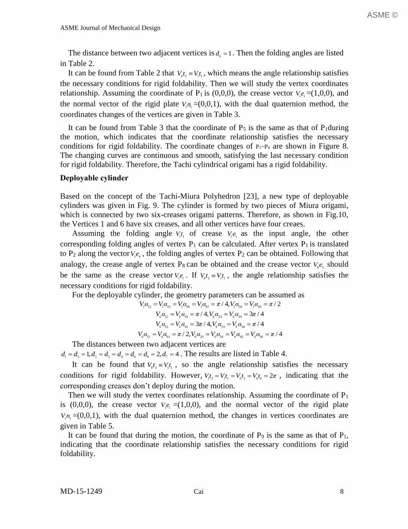
Tachi cylindrical origami
Figure 7(a) shows the formation of Tachi cylindrical origami [22]. Mirror the Miura-ori
and then a Tachi origami is obtained. Figure 7(b) shows a typical unit of Tachi cylinder.
The Tachi cylinder is rigidly foldable and has a single degree of freedom. Besides it has
both flat configurations in fully folded state and fully unfolded state.
After analyzing the typical unit, it can be obtained that P1 and P3 are two-dimensional
single-vertices, P2 and P4 are three-dimensional vertices which cannot fold flatly.
Assuming the folding angle1 1
V t of crease 1 1
V e as the input angle, all other corresponding
folding angles of vertex P1 can be obtained. After vertex P1 is translated to P2 along the
vector1 3
V e , all the folding angles of vertex P2 can be calculated. Following that analogy,
the folding angles of vertices P3 and P4 can be obtained. The crease vector 4 3
V e should be
the same as the crease vector1 1
V e . Therefore, if 4 3 1 1
V t V t , the angle relationship satisfies
the necessary condition of rigid foldability.
For the Tachi typical unit, the geometric parameters can be assumed as
1 12 1 41 3 23 3 343 / 4Vα Vα V α V α π ,
1 23 1 34 3 12 3 41/ 4Vα Vα V α V α π ,
2 12 2 23 2 34 2 413 / 4V α V α V α V α π ,
4 12 4 23 4 34 4 41/ 4V α V α V α V α π .
ASME ©
ASME Journal of Mechanical Design
MD-15-1249 Cai 8
The distance between two adjacent vertices is 1k
d . Then the folding angles are listed
in Table 2.
It can be found from Table 2 that 4 3 1 1
V t V t , which means the angle relationship satisfies
the necessary conditions for rigid foldability. Then we will study the vertex coordinates
relationship. Assuming the coordinate of P1 is (0,0,0), the crease vector 1 1
V e =(1,0,0), and
the normal vector of the rigid plate 1 1
V n =(0,0,1), with the dual quaternion method, the
coordinates changes of the vertices are given in Table 3.
It can be found from Table 3 that the coordinate of P5 is the same as that of P1during
the motion, which indicates that the coordinate relationship satisfies the necessary
conditions for rigid foldability. The coordinate changes of P1~P4 are shown in Figure 8.
The changing curves are continuous and smooth, satisfying the last necessary condition
for rigid foldability. Therefore, the Tachi cylindrical origami has a rigid foldability.
Deployable cylinder
Based on the concept of the Tachi-Miura Polyhedron [23], a new type of deployable
cylinders was given in Fig. 9. The cylinder is formed by two pieces of Miura origami,
which is connected by two six-creases origami patterns. Therefore, as shown in Fig.10,
the Vertices 1 and 6 have six creases, and all other vertices have four creaes.
Assuming the folding angle1 1
V t of crease 1 1
V e as the input angle, the other
corresponding folding angles of vertex P1 can be calculated. After vertex P1 is translated
to P2 along the vector1 4
V e , the folding angles of vertex P2 can be obtained. Following that
analogy, the crease angle of vertex P8 can be obtained and the crease vector 8 3
V e should
be the same as the crease vector1 1
V e . If 8 3 1 1
V t V t , the angle relationship satisfies the
necessary conditions for rigid foldability.
For the deployable cylinder, the geometry parameters can be assumed as
1 12 1 23 1 56 1 61 1 34 1 45/ 4, / 2Vα Vα Vα Vα π Vα Vα π
12 41 23 34/ 4, 3 / 4
k k k kV α V α π V α V α π
12 41 23 343 / 4, / 4
k k k kV α V α π V α V α π
6 12 6 61 6 23 6 34 6 45 6 56/ 2, / 4V α V α π V α V α V α V α π
The distances between two adjacent vertices are
1 5 2 3 4 6 8 71, 2, 4d d d d d d d d . The results are listed in Table 4.
It can be found that8 3 1 1
V t V t , so the angle relationship satisfies the necessary
conditions for rigid foldability. However,1 3 1 5 6 2 6 6
2Vt V t V t V t π , indicating that the
corresponding creases don’t deploy during the motion.
Then we will study the vertex coordinates relationship. Assuming the coordinate of P1
is (0,0,0), the crease vector 1 1
V e =(1,0,0), and the normal vector of the rigid plate
1 1V n =(0,0,1), with the dual quaternion method, the changes in vertices coordinates are
given in Table 5.
It can be found that during the motion, the coordinate of P9 is the same as that of P1,
indicating that the coordinate relationship satisfies the necessary conditions for rigid
foldability.
ASME ©

ASME Journal of Mechanical Design
MD-15-1249 Cai 9
The changes of coordinate P1~P8 are shown in Fig. 11. The curves are continuous and
smooth, satisfying the last necessary condition for rigid foldability. Therefore, the
deployable cylinder can be proved rigidly foldable via the proposed method.
CONCLUSIONS
In this paper, we established a new method to study the rigid foldability of the multi-
vertex cylindrical-shaped origami patterns. After analyzing the folding angles via the
QRS method for multi-vertex crease origami, calculating the coordinates of all vertices
using the dual quaternion method, the rigid foldability can then be checked. Compared
with the original QRS method proposed by Wu and You [7], the method is able to check
the rigid foldability of multi-vertex cylindrical origami. Through two examples, we
demonstrated that the proposed method can analyze the folding angles and coordinates of
vertices, and thereby predict its rigid foldability. However, due to the complexity of both
the folding angles and vertex coordinates of the multi-vertex origami, we have yet to use
the proposed method to develop an algorithm for detecting more cylindrical origami with
rigid foldability, which will be the further study of this topic.
ACKNOWLEDGMENTS
The work presented in this article was supported by the National Natural Science
Foundation of China (Grant No. 51308106 and No. 51278116), the Natural Science
Foundation of Jiangsu Province (Grant No. BK20130614), the Specialized Research
Fund for the Doctoral Program of Higher Education (Grant No. 20130092120018), a
Project Funded by the Priority Academic Program Development of Jiangsu Higher
Education Institutions and the Excellent Young Teachers Program of Southeast
University. Authors thank all the anonymous reviewers for their valuable comments and
thoughtful suggestions which improved the quality of the presented work.
ASME ©
ASME Journal of Mechanical Design
MD-15-1249 Cai 10
REFERENCES [1] Sorguc A G, Hagiwara I, Selcuk S A. Origami in Architecture: A Medium of Inquiry
for Design in Architecture. Metu Jfa, 2009, 26(2): 235-247.
[2] Hagiwara I. From Origami to Origamics. Science Japan Journal, 2008, July, 22-25.
[3] Guest S D. Deployable structures: Concepts and Analysis. PhD thesis, Cambridge
University, Cambridge, UK, 1996.
[4] Ma J, You Z. Energy Absorption of Thin-Walled Square Tubes with a Prefolded
Origami Pattern-Part I: Geometry and Numerical Simulation. Journal of Applied
Mechanics-Transactions of the ASME, 2014, 81(1): 011003
[5] Ma J, You Z. Energy absorption of thin-walled beams with a pre-folded origami
pattern. Thin-walled Structures, 2013, 73: 198-206
[6] Demaine E D, O’Rourke, J. A survey of folding and unfolding in computational
geometry. In Mathematical sciences research institute publications, 2005, vol. 52, pp.
167-211. Berkeley, CA: MSRI Publications.
[7] Wu WN, You Z. Modelling rigid origami with quaternions and dual quaternions,
Proceedings of the Royal Society A: Mathematical, Physical and Engineering
Sciences, 2010, 466: 2155-2174
[8] Miura K. Map Fold a La Miura Style, Its Physical Characteristics and Application to
the Space Science. In Research of Pattern Formation, edited by R. Takaki, pp. 77-90.
Tokyo: KTK Scientific Publishers, 1989.
[9] Miura K. Method of packaging and deployment of large membranes in space, In:
Proceedings of 31stCongress of International Astronautics Federation (IAF-80-A31),
Tokyo, Japan, 1980, 1-10.
[10] Huffman D. 1976 Curvature and crease: a primer on paper. IEEE Trans. Comput. C-
25, 1010–1019.(doi:10.1109/TC.1976.1674542)
[11] Miura K. 1989 A Note on Intrinsic Geometry of Origami. In Proc. 1st Int. Meet. of
Origami Science and Technology, 6-7 December, Ferrara, Italy (ed. H. Huzita), pp.
239–249.
[12] Belcastro, S. & Hull, T. 2002, Modeling the folding of paper into three dimensions
using affine transformations. Linear Algebra Appl. 348, 273–282.
[13] Watanabe N, Kawaguchi K. 2006, The method for judging rigid foldability. In
Origami 4Proc. 4th Int. Conf. on Origami in Science, Mathematics, and Education,
Pasadena, CA, September 8-10,, pp. 165–174. Natick, MA: AK Peters
[14] Streinu I, Whiteley W. 2005 Single-vertex origami and spherical expansive motions.
Lecture Notes in Computer Science, no. 3742, pp. 161-173. Berlin, Germany:
Springer.
[15] Tachi T. Generalization of Rigid Foldable Quadrilateral Mesh Origami. Proceedings
of the International Association for Shell and Spatial Structures Symposium 2009,
edited by Albert Domingo and Carlos Lazaro, pp. 2287-2294. Madrid: IASS, 2009.
[16] Wei GW, Dai JS. Origami-Inspired Integrated Planar-Spherical Overconstrained
Mechanisms, J. Mech. Des., 2014, 136(5), 051003
[17] Wang KF, Chen Y. Rigid Origami to Fold a Flat Paper into a Patterned Cylinder,
The 5th international conference on origami in science, Singapore, 2010.
[18] Liu SC, Chen Y, Lu GX. The rigid origami patterns for flat surface, Proceedings of
the ASME 2013 International Design Engineering Technical Conferences and
ASME ©

ASME Journal of Mechanical Design
MD-15-1249 Cai 11
Computers and Information in Engineering Conference, IDETC/CIE 2013, August 4-
7, 2013, Portland, Oregon, USA
[19] Liu SC, Lv WL, Chen Y, Lu GX. Deployable Prismatic Structures with Origami
Patterns, Proceedings of the ASME 2014 International Design Engineering Technical
Conferences & Computers and Information in Engineering Conference, IDETC/CIE
2014 August 17-20, 2014, Buffalo, New York, USA
[20] Wu W, You Z. A solution for folding rigid tall shopping bags, Proc. R. Soc. London,
Ser. A, 2011, 467, 2561-2574.
[21] Miura K, Tachi T, Miyazaki Y. Foldable space structures-foldable cylindrical
polyhedron and IKAROS solar sail, IASS-APCS 2012 Symposium, May 21-24,
2012, Seoul, Korea
[22] Tachi T. One-DOF Cylindrical Deployable Structures with Rigid Quadrilateral
Panels, in: A. Domingo, C. Lazaro (Eds.) The International Association for Shell and
Spatial Structures Symposium 2009, Madrid: IASS, 2009, pp. 2295–2305.
[23] Miura K, Tachi T. Synthesis of rigid-foldable cylindrical polyhedral, Symmetry: Art
and Science, Gmuend, Austria, 2010
ASME ©

ASME Journal of Mechanical Design
MD-15-1249 Cai 12
Figure Captions List
Fig. 1 Origami crease pattern (a) The initially flat state (b) a folding
configuration
Fig. 2 The closed-loop rotation sequence of the characteristic vectors
decomposed into eight steps in the rotating vector model of the single-
vertex fourfold system
Fig. 3 The modified Miura origami pattern
Fig. 4 The cylinder configuration
Fig. 5 The serial numbers of the vertex and fold lines
Fig. 6 The coordinates of Vertex 0
Fig. 7 Tachi origami model
Fig. 8 The coordinate changes of P1~P4
Fig. 9 Crease pattern of a deployable cylinder
Fig. 10 Vertices of the deployable cylinder (a) Vertex P1 (b) Vertex P2~ P5 (c)
Vertex P6 (d) Vertex P7~ P8
Fig. 11 The coordinate changes of P1~P8
ASME ©

ASME Journal of Mechanical Design
MD-15-1249 Cai 13
Table Caption List
Table 1 The coordinates of Vertex 0
Table 2 The folding angles of Tachi typical unit
Table 3 The coordinates changes of the vertices
Table 4 The folding angles of Deployable cylinder
Table 5 The coordinates changes of the vertices
ASME ©
ASME Journal of Mechanical Design
MD-15-1249 Cai 14
(a) The initially flat state
(b)a folding configuration
Fig.1 Origami crease pattern
Fig. 2 The closed-loop rotation sequence of the characteristic vectors decomposed into
eight steps in the rotating vector model of the single-vertex fourfold system.
ASME ©

ASME Journal of Mechanical Design
MD-15-1249 Cai 15
Fig.3 The modified Miura origami pattern
Fig.4 The cylinder configuration
Fig. 5 The serial numbers of the vertex and fold lines
-20-10
010
-5
0
5-20
-10
0
10
xy
z
Fig.6 The coordinates of Vertex 0
ASME ©

ASME Journal of Mechanical Design
MD-15-1249 Cai 16
(a)Formation of Tachi origami
(b)A typical unit
Fig.7 Tachi origami model
-1
0
1
0
0.5
1-0.8
-0.6
-0.4
-0.2
0
xy
z
P1
P2
P3
P4
Figure 8 The coordinate changes of P1~P4
Figure 9 Crease pattern of a deployable cylinder
ASME ©
ASME Journal of Mechanical Design
MD-15-1249 Cai 17
(a)Vertex P1
P2 P3 P4 P5V2e1
V2e2
V2e3
V2e4
(b)Vertex P2~ P5
(c)Vertex P6
(d)Vertex P7~ P8
Fig. 10 Vertices of the deployable cylinder
-20
24
68
0
2
4
-4
-3
-2
-1
0
xy
z
P1
P2
P3
P4
P5
P6
P7
P8
Fig. 11The coordinate changes of P1~P8
ASME ©
ASME Journal of Mechanical Design
MD-15-1249 Cai 18
Table 1 The coordinates of Vertex 0
V1t1 (rad) 0 0.4 0.8 1.2 1.6
V0Px 0 0.001 0.0181 0.1264 0.6342
V0Py 0 0.0028 0.0404 0.1911 0.5019
V0Pz 0 -0.0001 0.0169 0.1301 0.5161
V1t1 (rad) 2 2.4 2.8 π
V0Px 2.5942 6.6825 -1.737 -18
V0Py 0.6148 -0.9844 -2.4346 0
V0Pz 0.9588 -2.5308 -14.1109 0
ASME ©

ASME Journal of Mechanical Design
MD-15-1249 Cai 19
Table 2 The folding angles of Tachi typical unit V1t1(
Mountain) π 3.4 3.8 4.2 4.6 5 5.4 5.8 2π
V1t2(
Mountain) 3.1416 3.505 4.0417 4.5237 4.9442 5.3112 5.638 5.9382 6.2832
V2t2(
Mountain) 6.2832 5.9198 5.383 4.9011 4.4805 4.1135 3.7868 3.4866 3.1416
V3t2(
Mountain) 3.1416 3.505 4.0417 4.5237 4.9442 5.3112 5.638 5.9382 6.2832
V4t2(
Mountain) 6.2832 5.9198 5.383 4.9011 4.4805 4.1135 3.7868 3.4866 3.1416
V4t3(
Mountain) π 3.4 3.8 4.2 4.6 5 5.4 5.8 2π
Table 3 The coordinates changes of the vertices V1t1 (rad) π 3.4 3.8 4.2 4.6 5 5.4 5.8 2π
V1Px 0 0 0 0 0 0 0 0 0
V1Py 0 0 0 0 0 0 0 0 0
V1Pz 0 0 0 0 0 0 0 0 0
V2Px -1 -0.9673 -0.8108 -0.5938 -0.3851 -0.2182 -0.1005 -0.0295 0
V2Py 0 0.0327 0.1892 0.4062 0.6149 0.7818 0.8995 0.9705 1
V2Pz 0 -0.2513 -0.5539 -0.6946 -0.6882 -0.5841 -0.4252 -0.2391 0
V3Px 0 0.0327 0.1892 0.4062 0.6149 0.7818 0.8995 0.9705 1
V3Py 0 0.0327 0.1892 0.4062 0.6149 0.7818 0.8995 0.9705 1
V3Pz 0 -0.2513 -0.554 -0.6945 -0.6882 -0.5841 -0.4252 -0.2391 0
V4Px 1 1 1 1 1 1 1 1 1
V4Py 0 0 0 0 0 0 0 0 0
V4Pz 0 0 0 0 0 0 0 0 0
V5Px 0 0 0 0 0 0 0 0 0
V5Py 0 0 0 0 0 0 0 0 0
V5Pz 0 0 0 0 0 0 0 0 0
ASME ©

ASME Journal of Mechanical Design
MD-15-1249 Cai 20
Table 4 The folding angles of Deployable cylinder V1t1(
Mountain) π 3.4 3.8 4.2 4.6 5 5.4 5.8 2π
V1t2(Valley
) 3.1416 2.7782 2.2415 1.7595 1.339 0.972 0.6452 0.345 0
V1t3(
Mountain) 6.2832 6.2832 6.2832 6.2832 6.2832 6.2832 6.2832 6.2832 6.2832
V2t2(Valley
) 3.1416 2.7782 2.2414 1.7595 1.339 0.9719 0.6452 0.345 0
V3t2(
Mountain) 3.1416 3.505 4.0417 4.5237 4.9442 5.3112 5.638 5.9382 6.2832
V4t2(
Mountain) 3.1416 3.505 4.0417 4.5237 4.9442 5.3112 5.638 5.9382 6.2832
V5t2(Valley
) 3.1416 2.7782 2.2415 1.7595 1.339 0.972 0.6452 0.345 0
V6t2(
Mountain) 6.2832 6.2832 6.2832 6.2832 6.2832 6.2832 6.2832 6.2832 6.2832
V6t3(Valley
) 3.1416 2.7782 2.2415 1.7595 1.339 0.972 0.6452 0.345 0
V7t2(
Mountain) 3.1416 3.505 4.0417 4.5237 4.9442 5.3112 5.638 5.9382 6.2832
V8t2(
Mountain) 3.1416 3.505 4.0417 4.5237 4.9442 5.3112 5.638 5.9382 6.2832
V8t3(
Mountain) 3.1416 3.4 3.8 4.2 4.6 5 5.4 5.8 6.2832
ASME ©

ASME Journal of Mechanical Design
MD-15-1249 Cai 21
Table 5 The coordinates changes of the vertices V1t1 (rad) π 3.4 3.8 4.2 4.6 5 5.4 5.8 2π
V1Px 0 0 0 0 0 0 0 0 0
V1Py 0 0 0 0 0 0 0 0 0
V1Pz 0 0 0 0 0 0 0 0 0
V2Px 1 0.9674 0.8108 0.5938 0.3851 0.2182 0.1005 0.0295 0
V2Py 0 0.0326 0.1892 0.4062 0.6149 0.7818 0.8995 0.9705 1
V2Pz 0 -0.2513 -0.5539 -0.6946 -0.6882 -0.5841 -0.4252 -0.2392 0
V3Px 3 2.7104 1.4401 0.0042 -1.0215 -1.5914 -1.8591 -1.9671 -2
V3Py 0 0.159 0.8029 1.371 1.5621 1.464 1.2611 1.0849 1
V3Pz 0 -1.2238 -2.3504 -2.3442 -1.7484 -1.0939 -0.5962 -0.2673 0
V4Px 5 4.6451 3.0615 1.1918 -0.2512 -1.1551 -1.658 -1.9081 -2
V4Py 0 0.2243 1.1814 2.1834 2.7918 3.0277 3.0601 3.026 3
V4Pz 0 -1.7265 -3.4584 -3.7333 -3.1248 -2.262 -1.4467 -0.7457 0
V5Px 7 6.6451 5.0615 3.1918 1.7488 0.8449 0.342 0.0919 0
V5Py 0 0.2243 1.1815 2.1833 2.7917 3.0278 3.0601 3.026 3
V5Pz 0 -1.7264 -3.4584 -3.7333 -3.1248 -2.2619 -1.4467 -0.7457 0
V6Px 8 7.6125 5.8723 3.7856 2.134 1.063 0.4425 0.1213 0
V6Py 0 0.2569 1.3708 2.5895 3.4066 3.8097 3.9595 3.9965 4
V6Pz 0 -1.9777 -4.0124 -4.4279 -3.813 -2.846 -1.8719 -0.9848 0
V7Px 6 5.8694 5.2429 4.3752 3.5406 2.8726 2.4021 2.1179 2
V7Py 0 0.1306 0.7571 1.6247 2.4593 3.1275 3.5979 3.8821 4
V7Pz 0 -1.0053 -2.2159 -2.7781 -2.7527 -2.3361 -1.701 -0.9567 0
V8Px 2 2 2 2 2 2 2 2 2
V8Py 0 0 0 0 0 0 0 0 0
V8Pz 0 0 0 0 0 0 0 0 0
V9Px 0 0 0 0 0 0 0 0 0
V9Py 0 0 0 0 0 0 0 0 0
V9Pz 0 0 0 0 0 0 0 0 0
ASME ©