the following modifications were based on an article in l ... · the following modifications were...
TRANSCRIPT

The following modifications were based on an article in L.A. Audiofile Bulletin #29
1988. ( Attached with permission at the end of my document )
AR XA and Grace tone arm:
Grace 707 arm plus the mounting parts: 11.5 ounces
AR XA arm including all the parts cut off the T bar: 10.3 ounces.
It’s the right length, it will fit fine under the cover, as long as you have a later cover,
I believe you will need some spacers on the older cover because of the higher
mounting stance of the Grace arm.
Modified T bar and mounting parts. To save more weight, I used .090 aluminum
instead of the .125 recommended in the article. It’s easier to hand modify and is
still thicker that the original T bar surface. I also made it a bit shorter. The 2 large
flat washers are nylon 2” dia. with 3/4” holes. And some #8 hardware.
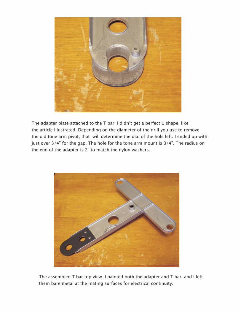
The adapter plate attached to the T bar. I didn’t get a perfect U shape, like
the article illustrated. Depending on the diameter of the drill you use to remove
the old tone arm pivot, that will determine the dia. of the hole left. I ended up with
just over 3/4” for the gap. The hole for the tone arm mount is 3/4”. The radius on
the end of the adapter is 2” to match the nylon washers.
The assembled T bar top view. I painted both the adapter and T bar, and I left
them bare metal at the mating surfaces for electrical continuity.
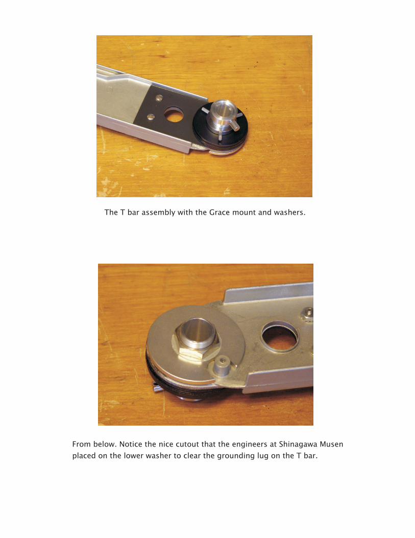
The T bar assembly with the Grace mount and washers.
From below. Notice the nice cutout that the engineers at Shinagawa Musen
placed on the lower washer to clear the grounding lug on the T bar.
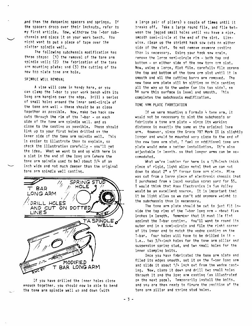
Nibble away some material
to enlarge the hole for a
better view of the new tone arm
mounting hole on the T bar.
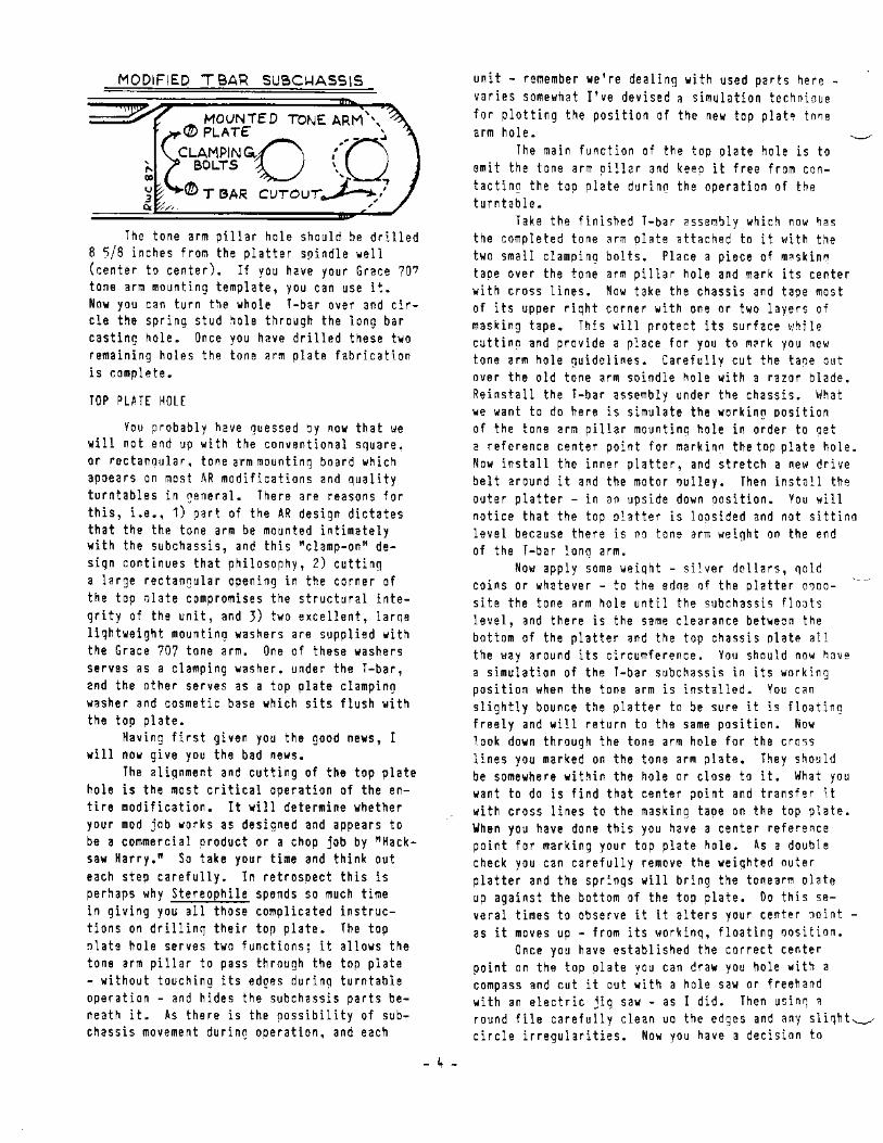
Grace mount top washer
Cut line
T bar
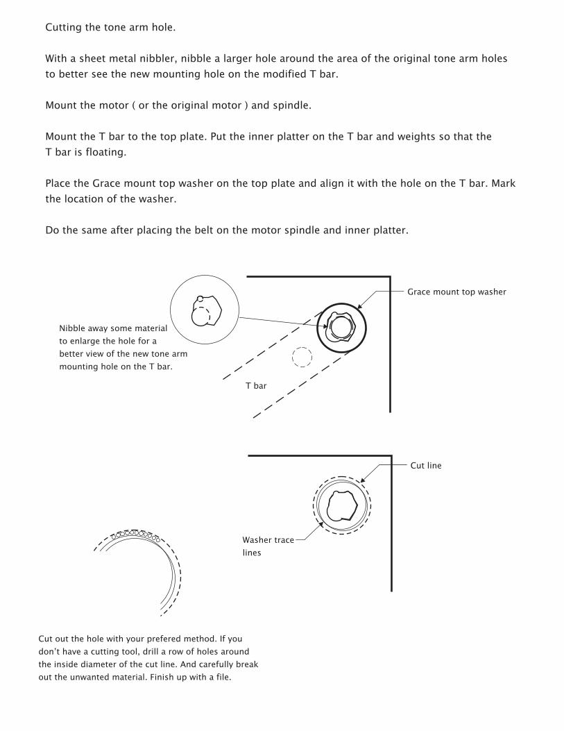
Cutting the tone arm hole.
With a sheet metal nibbler, nibble a larger hole around the area of the original tone arm holes
to better see the new mounting hole on the modified T bar.
Mount the motor ( or the original motor ) and spindle.
Mount the T bar to the top plate. Put the inner platter on the T bar and weights so that the
T bar is floating.
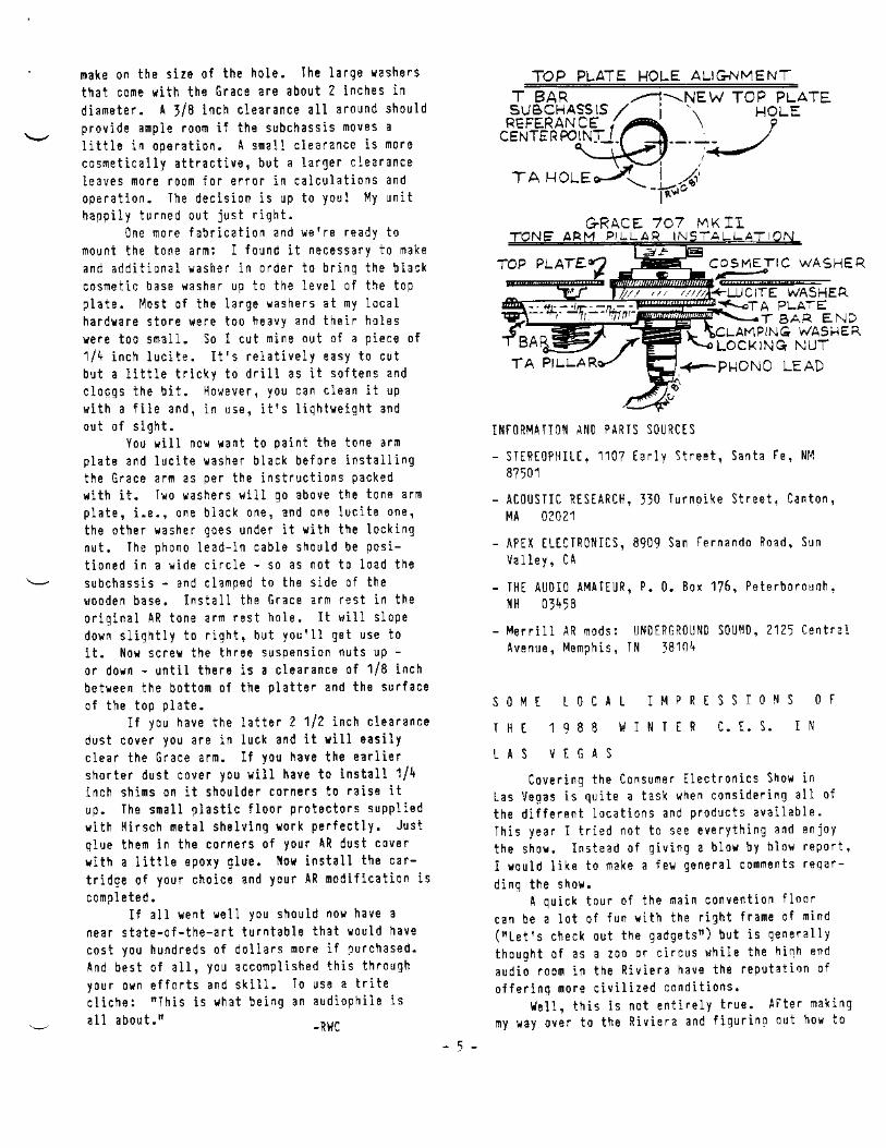
Place the Grace mount top washer on the top plate and align it with the hole on the T bar. Mark
the location of the washer.
Do the same after placing the belt on the motor spindle and inner platter.
Washer trace
lines
Cut out the hole with your prefered method. If you
don’t have a cutting tool, drill a row of holes around
the inside diameter of the cut line. And carefully break
out the unwanted material. Finish up with a file.
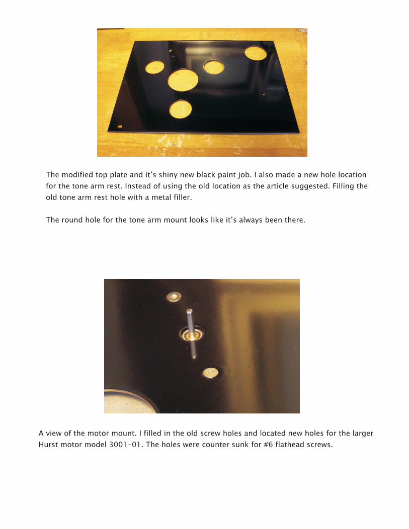
The modified top plate and it’s shiny new black paint job. I also made a new hole location
for the tone arm rest. Instead of using the old location as the article suggested. Filling the
old tone arm rest hole with a metal filler.
The round hole for the tone arm mount looks like it’s always been there.
A view of the motor mount. I filled in the old screw holes and located new holes for the larger
Hurst motor model 3001-01. The holes were counter sunk for #6 flathead screws.

The modified Hurst motor. The mounting holes to were drilled out to .25” and
grommets for vibration dampening installed. The motor should be installed loose
enough for the grommets to provide some cushioning effect. The mounting holes
on the top plate were positioned in line with the center platter hole so that belt
tension would not tilt the spindle. Secure the hardware with lock washers or Locktite.
The completed top plate with motor and T bar installed.

View of completed chassis. New AC power cord, Acoustic Research 3 Ft. audio cables, all
new wiring and a NOS Stackpole switch comprise the electrical components. Along with
new capacitors for the switch and motor.
The ground lead is from an original AR turntable cable. I also turned the old tone arm wiring
terminals into a ground bus. The green wires are ground leads to the AC switch wire shielding
and to the Hurst motor. The motor will need separate grounding since grommets now isolate
it from the top panel.
Close up showing the ground bus and tone arm connection. Allow enough audio cable so that it
can flex freely with the T bar motion.
The silicone I placed on the T bar seems to do a nice job of dampening most of the tinny
resonance of the T bar without adding too much weight ( like adding lead strips ).
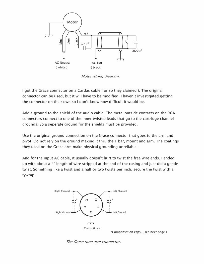
I got the Grace connector on a Cardas cable ( or so they claimed ). The original
connector can be used, but it will have to be modified. I haven’t investigated getting
the connector on their own so I don’t know how difficult it would be.
Add a ground to the shield of the audio cable. The metal outside contacts on the RCA
connectors connect to one of the inner twisted leads that go to the cartridge channel
grounds. So a seperate ground for the shields must be provided.
Use the original ground connection on the Grace connector that goes to the arm and
pivot. Do not rely on the ground making it thru the T bar, mount and arm. The coatings
they used on the Grace arm make physical grounding unreliable.
And for the input AC cable, it usually doesn’t hurt to twist the free wire ends. I ended
up with about a 4” length of wire stripped at the end of the casing and just did a gentle
twist. Something like a twist and a half or two twists per inch, secure the twist with a
tywrap.
Chassis Ground
Right Channel Left Channel
Right Ground Left Ground
.25uf
.022uf
AC Neutral
( white )
AC Hot
( black )
Motor
blu
e
blu
e
red
bla
ck
**
*Compensation caps. ( see next page )

The completed AR table with a NOS Shure Bros. V15 type III HE.
A note on the audio cable. I was unable to get an answer from AR ( who’s not really AR anymore,
it’s Audiovox ) about the capacitance of the cable. Judging from what I can gather though, I should
be in the upper 300 to lower 400pf range for all the wiring.
Originally Shure recommended 400 - 500pf for the capacitance of the wiring. But later tests of the
cartridge stated that more like 300pf is the proper value.
And at the same time testing with different values of capacitance did not show any significant
degradation of the frequency response.
If your using something different from a Shure V15 type III, then that doesn’t matter much to
you. Though be aware of the requirements of your selected cartridge.
Excessive capacitance can always be compensated by installing a compensation capacitor in parallel
with the tone arm output cable and tone arm connector.

Materials Used:
Nylon Washers McMaster Carr p/n 96371A212
.090 Aluminum plate McMaster Carr p/n 8973K88
Grommets McMaster Carr p/n 9307K13
AC cable RadioShack Appliance cord ( cut off 2 pin appliance conn. )
Audio Cable Acoustic Research p/n AP031
Grace 707 Tone arm Where ever you can find one.
AC Syncronous Motor Hurst Manufacturing p/n 3001-001
Motor Capacitor, .25uf 600VAC Provided with motor
Switch Capacitor, .022uf 600VAC Mouser p/n 539-150223J630DB
Misc. Hardware Local Hardware store
Tools Used:
Power Drill & drill set
Small/large half round file
Spindle puller*
Hand nibbler tool for sheet metal
82 degree counter sink
Solder iron
* “The Puller” #45-4 Made by North West Short Line