the fundamentals of iv (current/voltage) measurement of smu
TRANSCRIPT

1
The Fundamentals of
IV (Current/Voltage)
Measurement of
SMU

2
Why Are Triaxial Cables Needed for Low-Current?
BNC (Coaxial) Cable: Triaxial Cable:
Leakage Current: Leakage Current:
Triaxial cable reduces leakage current by a factor of 100,000,000.

3
What is a 4-Wire (Kelvin) Measurement?
Rcable
Rcable
Rcable
Rcable
IForce
+ - VSense
I=0 I=0
Force Line 1 Force Line 2
Sense Line 1 Sense Line 2
RDUT
Eliminate cable resistance from the measurement

4
Example Instrument Outputs
(Banana Jack)
Sense Force Guard
High
Low
± 250V = M
ax ± 210V = Max
By default the low outputs are tied to chassis groun
d, but in this case they can be floated up to 250 V
above or below chassis ground if desired.
This tells you the maximum
allowable voltage (210 V in
this case) between the high
and low inputs.
When making a basic 2-wire
measurement you should us
e the Force outputs.
4-wire measurements requir
e the use of the Sense lines
in addition to the Force lines
.

5
Source/Measure Unit
(SMU) Introduction
6
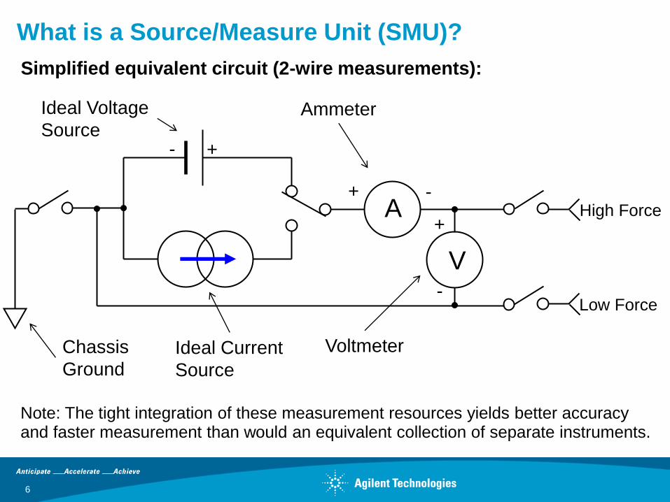
What is a Source/Measure Unit (SMU)?
Note: The tight integration of these measurement resources yields better accuracy and faster measurement than would an equivalent collection of separate instruments.
Simplified equivalent circuit (2-wire measurements):
Ideal Voltage
Source
Ideal Current
Source
Ammeter
Voltmeter Chassis
Ground
A
V
+ -
+
-
High Force
Low Force
+ -

7
Why Would You Use an SMU for IV Measurements?
VFIM (Force voltage & measure
current) IFVM (Force current & measure
voltage)
A
DUT DUTV
An SMU integrates the following capabilities into each channel:
• Four-quadrant voltage source
• Four-quadrant current source
• Voltage meter
• Current meter
Here are the two most common modes of operation:

8
Why Use a Benchtop SMU for IV Measurements?
Multimeter
Multimeter
DC Voltage Source
DC Voltage Source
DUT
RL
Bench-top setup example
for 4-terminal DUT
IN OUTDUTIN OUT
B2900A setup example
for 4-terminal DUT
Channel 2 on
the back side
Channel 1
Problem: Limited bench-top space for single-function instruments.
Solution: A benchtop SMU reduces the number of instruments and reduces m
essy wiring.
Non-SMU setup example
for 4-terminal device SMU setup example for 4
-terminal device

9
Low current
measurement
TECHNIQUES

10
Low-Current Measurement Challenges ???
• How do I eliminate electromagnetic interference?
• How do I avoid creating ground loops?
• What is measurement ranging and how do I optimize it?
• Why is integration time important in eliminating noise?
• How do I eliminate voltage and current transients?

11
Use Shielding to Avoid Electromagnetic Interference
Shielding Box
Probing Equipment and DUT
Note: Shielding is not the same
as guarding.

12
Avoiding Ground Loops
Conductive planes tied together at o
nly one point cannot have any curre
nt flowing between them.
Conductive planes tied together at m
ultiple points creates a loop for curre
nt (a condition to be avoided).
Do not connect up equipment to ground at more than one point!

13
Understanding Measurement Ranging - 1
All measurement circuitry needs to swi
tch in and out various resistors in orde
r to measure currents and voltages at
different levels.
The measurement range determines
the maximum measurement resoluti
on that you can obtain*.
*Typically 5 decades below the measurement range.

14
Understanding Measurement Ranging - 2
10 pA
100 pA
1 nA
10 mA
100 mA
Fixed Ranging – Always stay in
the same measurement range
Limited Ranging – Never go
below the specified range limit
Auto Ranging – Go as low as
necessary to make an accurate
measurement (down to the lowest
range supported if necessary)
Current Measurement Range

15
Integration Time Eliminates Measurement Noise
AC Voltage
Time
Time
Measured Value Averaged over m
ultiple power line
cycles
Integration DOES NOT have any effect on the measurement resolution.

16
Step #1: Perform Self-calibration
Before performing Self Calibration After performing Self Calibration
1 nA
1 fA
1 pA 100 fA
Almost all instruments designed for low-current mea
surement have some sort of self-calibration mechani
sm. It is important that you DO THIS before attempt
ing a low-current measurement.
Note: B2900A example shown
Press the System > Cal/Test function keys
From the front panel:
Press OK to perform Self-calibration

17
Step #2: Select the Correct Current Measurement
Range
Using 1 mA Current Measurement Range: Using 10 nA Current Measurement Range:
1 nA
1 fA
10 pA 100 fA
From the front panel:
In Single View mode you can specify the
current measurement range.
Most instruments DO NOT boot up in their lowest m
easurement range. In this example notice the impro
vement in measurement performance obtained by c
hanging from the 1 mA current measurement range
to the 10 nA current measurement range.
Note: B2900A example shown

18
Step #3: Increase the Integration Time to Eliminate
Measurement Noise
Using SHORT(0.01 PLC) integration time: Using NORMAL (1 PLC) integration time:
1 nA
1 fA
1 pA 100 fA
From the front panel:
In Single View mode you can select the
measure-ment speed (integration time)
In general, low-current measurements need at least
1 power line cycle (PLC) of integration to obtain dec
ent results (in this example NORMAL integration). E
xtremely low currents and/or noisy environments ma
y require LONG integration (16 PLCs). You can use
MANUAL integration to select PLC values between t
hese two extremes.
Note: B2900A example shown

19
Step #4: Select an Appropriate Measurement Trigger
Delay Time
Using a Trigger Delay Time of 0 ms Using a Trigger Delay Time of 200 ms
1 nA
1 fA
5 pA 100 fA
From the front panel:
In Single View mode you can select the
measure-ment delay time
The length of the wait time depends primarily on the
size of the voltage step; larger voltage steps require
longer wait times. However, the magnitude of the c
apacitance being driven also impacts the wait time (l
arger C longer wait times).
Note: B2900A example shown

20
B2900A SMU series
features & benefits
Page 20

21
B2900A Series of Precision Source/Measure Units
B2900A Key Features:
1. Range of up to ±210 V and ±3 A (DC) / ±10.5 A (pulsed) p
rovides wider coverage for testing a variety of devices
2. Measurement resolution of 10 fA and 100 nV offers bette
r source and measurement performance
3. GUI for quick bench-top testing, debug and
characterization

22
Interactive Device Evaluation Can be Performed
Entirely from the Front Panel (4 Viewing Modes):
Dual Channel View (2-ch Units Only) Single Channel View
Graph View (I-V, I-t, and V-t plots) Roll View (similar to strip chart)

23
B2900A Series Sourcing Capabilities
Constant Linear Sweep
Single Double
Log Sweep
Single Double List Sweep
DC
Pulse
V or I
t
V or I
t
V or I
t
V or I
t
V or I
t
V or I
t
V or I
t
V or I
t
V or I
t
V or I
t
V or I
t
V or I
t
Source
Function
V or I
t
V or I
t
Arbitrary Waveform Generation The List Sweep function allows you to create arbitrary waveforms wi
th up to 2500 steps. The timing resolution varies by B2900A model
(20ms for B2901/02A, 10ms for B2911/12A ).
An icon appears in th
e GUI to indicate the t
ype of sweep function
selected.

24
B2900A Series Measurement Capabilities
High Speed Digitizing Capability In addition to its intrinsic measurement functions, the B2900A Series has an advanced trigger design that enables high speed digitizing measurements (20ms for B2901/02A, 10ms for B2911/12A).
V or I
t 20ms for B2901/02A 10ms for B2911/12A
:Measurement
The B2900A Series has four measurement functions that can be selected for either
channel using its front-panel GUI or SCPI commands.
Voltage Measurement
Current Measurement
Resistance Measurement
Power Measurement
Note: The Power Measurement function cannot be
specified when using remote control

25
B2900A Maximum Voltage and Current Output
Maximum Voltage Maximum Current
DC or Pulsed
210 V 0.105 A
21 V 1.515 A2
6 V 3.03 A2
Pulsed only1
200 V 1.515 A
6 V 10.5 A
1. Maximum duty cycle is 2.5%
2. On 2-channel units some additional restrictions apply on the combined current outp
ut of both channels (please refer to data sheet)
26
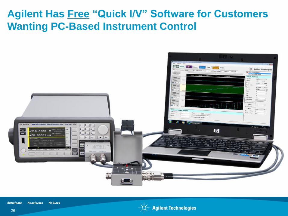
Agilent Has Free “Quick I/V” Software for Customers
Wanting PC-Based Instrument Control

FINAL REMARKS
27

28
Additional Agilent SMU Instrument Products
Year 80 85 90 95 00 05 10
HP 4142B
4155/56 series 4145 series
E5260A/70B series
Modular SMU
Parameter
Analyzer
Bench-top SMUs B2900A series
B1500A/B1505A
Agilent has more then 30 years
of instrument SMU experience.
Device Analyzer
USB SMU
U2722A/23A N678xA SMU
Power Analyzer

29
Comparison of the B1500A & B1505A
Software
EasyEXPERT
– Tracer Test
– Classic Test
– Application Test
– Quick Test
Modules
MPSMU
HRSMU
ASU
HV-SPGU
WGFMU
Modules
HCSMU
HVSMU
Accessories
SCUU
GSWU
Accessories
HV Bias-T
Module Select
or Unit
Max I/V - 1 A, 200 V
Meas. Res. - 0.1 fA, 0.5 mV
Modules
HPSMU
MFCMU
B1500A B1505A
Max I/V - 40 A, 3000 V
Meas. Res. - 10 fA, 2 mV

Thank you
30