the fuzzy barrier: a mechanism for high speed
TRANSCRIPT
The Fuzzy Barrier: A Mechanism for High Speed
Synchronization of Processors*
Rajiv Gupta Philips Laboratories
North American Philips Corporation 345 Scarborough Road
Briarcliff Manor, NY 10510
Abstract - Parallel programs are commonly written using barriers to synchronize parallel processes. Upon reaching a barrier, a processor must stall until all parti- cipating processors reach the barrier. A software imple- mentation of the barrier mechanism using shared vari- ables has two major drawbacks. Firstly, the execution of the barrier may be slow as it may not only require execution of several instructions and but also result in hot-spot accesses. Secondly, processors that are stalled waiting for other processors to reach the barrier are essentially idling and cannot do any useful work. In this paper, the notion of the fuzzy barrier is presented, that avoids the above drawbacks. The first problem is avoided by implementing the mechanism in hardware. The second problem is solved by extending the barrier concept to include a region of statements that can be executed by a processor while it awaits synchronization. The barrier regions are constructed by a compiler and consist of several instructions such that a processor is ready to synchronize upon reaching the first instruction in this region and must synchronize before exiting the region. When synchronization does occur, the processors could be executing at any point in their respective bar- rier regions. The larger the barrier region, the more likely it is that none of the processors will have to stall. Preliminary investigations show that barrier regions can be large and the use of program transformations can significantly increase their size. Examples of situations where such a mechanism can result in improved perfor- mance are presented. Results based on a software implementation of the fuzzy barrier on the Encore mul- tiprocessor indicate that the synchronization overhead can be greatly reduced using the mechanism.
Keywords - multiprocessor systems, barrier synchroni- zation, parallelizing compilers.
Permission to copy without fee all or part of this material is granted provided that the copies are not made or distributed for direct commercial advantage, the ACM copyright notice and the title of the publication and its date appear, and notice is given that copying is by permission of the Association for Computing Machinery. To copy otherwise, or to republish, requires a fee and/ or specific permission.
0 1989 ACM O-8979 l-300-O/89/0004/0054 $1.50
1. Introduction
In order to achieve efficient parallel execution of tightly synchronizing streams of instructions, the development of fast synchronization mechanisms is essential. A commonly used mechanism for synchroniz- ing the parallel execution of streams is the barrier[l]. An application that creates streams for exploiting fine- grained parallelism schedules the parallel execution of streams on processors. Upon reaching a barrier the pro- cessor must wait until all participating processors reach the barrier. Barriers may be automatically introduced by a parallelizing compiler[2] or may be introduced explicitly by the programmer[3]. Barriers can be easily implemented in software using one or more shared vari- ables. However, such implementations entail significant run-time overhead as they require execution of several instructions in each stream in order to achieve synchron- ization. The synchronization overhead increases linearly, or for the best possible software implementa- tion, logarithmically[4] with the number of processors synchronizing at the barrier. Furthermore, the tech- niques are known to cause hot-spot accesses[4]. A pro- cessor upon reaching a barrier is idle until other proces- sors also reach the barrier[l]; thus no useful work is done by the processor while waiting to synchronize at the barrier. In this paper the notion of the fuzzy barrier, a mechanism that reduces both the run-time overhead and the idling of processors, is introduced.
In order to reduce the run-time overhead due to execution of additional instructions, barriers specified in instruction streams are detected by the hardware to ascertain when a processor is ready to synchronize. All participating processors are simultaneously informed of this event, and when all of the processors have reached the barrier, they simultaneously recognize that syn- chronization has taken place. This eliminates the run- time overhead caused by executing several instructions to achieve barrier synchronization. However, a single instruction is required to initialize a barrier. Once this has been done, the processors can repeatedly synchronize without executing any overhead instructions. Since the
l A patent application for the fuzzy barrier has already been Bled.
54
cost of using a barrier mechanism is extremely low it can be used frequently, thus facilitating the exploitation of fine-grained parallelism. Ho&pot accesses are avoided as the mechanism does not rely upon shared memory to achieve synchronization. The above strategy applies only to situations in which the processes synchronizing at a barrier are simultaneously executing on different processors. Thus, the number of streams synchronizing at a barrier can at most equal the number of processors in the system.
In order to reduce the idling time of processors at barriers, estimates of the time taken to execute different parts of a program are first used by the compiler to schedule approximately equal amounts of work on each processor between successive barrier synchronizations. However, even if the compiler distributes the computa- tion so that all processors execute identical code, they may not arrive at a barrier at the same time. The code being scheduled may contain conditional statements and different processors may follow different control paths and thus execute varying number of instructions. Furth- ermore, the times for memory accesses may vary for different processors. Due to a cache miss, a processor may fall behind in execution even if all processors are executing identical instructions. The barrier mechanism should be able to tolerate drift in the speed of execution of processors if idling at the barriers is to be reduced. The fuzzy barrier mechanism provides tolerance to this drift by specifying a range of instructions over which the synchronization is to take place rather than a specific point at which the processors must synchronize. Upon reaching the first instruction in this range, a processor is ready to synchronize. However, it can continue to exe- cute the remaining instructions in the region even if syn- chronization has not yet occurred. The mechanism, though implemented in hardware, relies upon the com- piler to discover this range of instructions. The proces- sors may be executing different instructions from the specified range of instructions at the time of synchroni- zation; hence the name fuzzy barrier.
A flexible barrier of the kind described has several advantages. If the processors in the system are pipe- lined, repeated synchronization is less likely to degrade the performance of the pipeline because the synchroniza- tion point is not exactly specified. Thus upon reaching a barrier, the processor may be able to issue instructions even if the synchronization has not taken place. Since there is almost no synchronization overhead, concurren- tizable loops requiring barrier synchronization can be efficiently executed on multiple processors even if the size of the loop body is relatively small. Application of transformations such as cycle shrinking[5] depend heavily upon use of barriers. Availability of an efficient barrier mechanism makes their application practical. A parallelizing compiler can employ such a mechanism to exploit instruction level parallelism using techniques similar to those used in VLIW machines[578].
In subsequent sections the semantics of the fuzzy barrier is described in detail. An example showing the
compilation process to exploit such a mechanism is presented. Code reorganization techniques to increase the range of instructions over which synchronization is to occur are described. Potential ways in which the mechanism can be used to achieve higher speed-ups are presented. An implementation of the mechanism in a prototype multiprocessor system based upon RISC(S] processors is currently in progress. The issues of using the barrier mechanism in presence of interrupts and sub- routine calls are not addressed in this paper.
2. Semantics of the Fuzzy Barrier
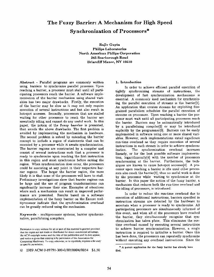
Instruction streams are viewed as consisting of barrier regions and non-barrier regions. In Fig. 1 the shaded regions represent barrier regions and the unshaded regions are non-barrier regions. Streams with no barrier regions have no barrier synchronizations, while a shaded region extending across all or a subset of streams indicates a barrier and forces the processors to synchronize. The barrier regions for different streams may contain varying number of instructions. The func- tionality of the fuzzy barrier is briefly described as fol- lows:
No processor can execute an instruction from its respective non-barrier region (UNSBADED2) fol- lowing the barrier region (SHADED) until all pro- cessors have executed the instructions in their respective non-barrier regions (UNSHADEDL) preceding the barrier region.
i.e., V i UC can be executed iff V j Cry have been executed
Pl PI PI1
4: Ji2 - IRRRRGIC+l(MSRNXDl)
REGION (SEMIED)
Fig. 1. Fuzzy Barrier
The semantics of the mechanism is described in detail below.
Definition: A processor is considered to have exited a region (barrier or non-barrier) of a stream if it has com- pleted the execution of all the instructions in that region. It has entered a region if it has started the exe- cution of an instruction from that region.
Definition: A processor is ready to synchronize if it has exited the non-barrier region preceding a barrier region. It should be noted that exiting this non-barrier region is not same as entering the barrier region for a pipelined machine, for a pipelined machine overlaps the execution of multiple instructions. Therefore, a processor may enter the barrier region before exiting the preceding non-barrier region.
Condition for Synchronization: Processors have

synchronized at a barrier if and only if they have all exited their respective non-barrier regions preceding the barrier region.
Condition for Stalling: A processor can enter a non- barrier region following a barrier region if and only if synchronization has occurred. Thus, if the synchroniza- tion is yet to occur when the processor exits the barrier region, it is not allowed to enter the non-barrier region and must idle. In other words, the execution of the stream is stalled.
From the above description it is clear that when the execution of a stream reaches the first instruction of a barrier region, it does not have to stop immediately but can continue to execute even if other streams haven’t reached their corresponding barrier regions. Similarly upon reaching the last instruction in a barrier region, the processor can continue even if other proces- sors have not reached the end of their corresponding barrier regions. If the barrier region for a stream con- sists of n instructions, then at the point of synchroniza- tion, the processor could have executed 0 to n instruc- tions from the barrier region. The tolerance of the mechanism to the variation in the rate at which each stream progresses is limited by the number of instruc- tions in the barrier regions. Thus, the larger the barrier regions, the less likely it is that the processors will stall.
3. Branch Instructions in Barrier Regions
The instructions that form a barrier region can contain unconditional as well as conditional branch instructions. Thus, any sequence of instructions that are consecutive along a control path in the program can form a barrier. Branches in the barrier region allow a barrier region to have multiple exits. Branches into a barrier region from non-barrier regions permit the bar- rier region to have multiple entry points. A processor enters the barrier when it executes an instruction from the barrier region and has crossed the barrier as soon as it executes the first instruction from a non-barrier region. The advantage of permitting branches in barrier code is that entire control structures, such as loops and if-statements, can be inciuded in a barrier region. Furth- ermore, the sequence of instructions forming the barrier may not be physically contiguous. Thus, for a loop whose iterations are separated by a barrier, the barrier region can contain code not only from the end of one iteration but also from the start of the subsequent itera- tion. As will be demonstrated through an example later in the paper, typically the barrier region corresponding to a barrier at the end of a loop body will, in fact, extend across consecutive iterations.
The destination of a branch instruction in the bar- rier region should either be an instruction in the same barrier region or an instruction in a non-barrier region. If the destination is within the barrier region, the proces- sor remains in the barrier region. On the other hand if the destination is in a non-barrier region, the processor exits the barrier region. The compiler should not gen-
erate code where control can be transferred directly from one barrier to another. Such branches can result in improper synchronization and deadlocks if the hardware cannot distinguish among different barriers. Consider the example in Fig. 2, where there are two barriers at which the processors must synchronize, and consider a branch instruction that transfers control of processor P, directly from barrier, to barrier, If this branch is taken, P, will cross both the barriers by synchronizing with P, only once when P, reaches barrier,. Also P, will be deadlocked at barrier, waiting for a synchronization that will never take place. It should be noted that the above problem will not arise in an implementation which explicitly specifies unique identifiers for barriers in the code.
Fig. 2. Invalid Branch
4. Compiler Support
In this section the compilation process for con- structing barrier and non-barrier regions is demon- strated using the Poisson solver[3] (Fig. 3(a)). The code shown in Fig. 3(b) is the non-deterministic parallel ver- sion of the algorithm. The example also demonstrates that code reordering can increase the size of the barrier region significantly.
The iterations of the inner loops of the Poisson solver can be executed in parallel. Thus, M2 processors can be used to execute a single iteration of the outer- most loop. A processor ready to begin a new iteration of the outer loop has to be informed when all work from the previous iteration has been completed. This can be achieved by introducing a barrier at the end of each iteration. The code executed by each of the M2 proces- sors is shown in Fig. 3(b). Storage related dependences among the parallel iterations due to loop variables are eliminated by creating private copies of i, j and k for each subtaek.
/’ Boundary conditions are held in rows/columns 0 and M+l l / int P[M+lJ[M+lJ;
for (k=l; k<=lO*M; k++) do seq for h-1: i<=M: i++l do ear
fo; (j-1; j<&; j$+) do par Plilljl - (P(ij[j+l] + P(i][j-l] + P[i+l/[j] + P[i-l](j])/4;
Fig. $(a). Poisson Solver
Processor P, ~ where 15 1,m <M:
Private i,j,k; i=l; j-m; ro;(k-1; k<=lO*M; ki+)
’ ~$I,- Wllj+ll + Plillj-11 + P[i+l][jl + P[i-l][jl)/4; 1 I
Fig. 3(b). Per Processor Tasks
56

The barrier region is constructed by examining instructions along the control flow path on which the barrier lies. The instructions preceding and following a barrier are candidates for inclusion in the barrier region. For the above example, since the barrier is at the end of a loop, these instructions include the instructions from two consecutive loop iterations. Our goal is to include as many instructions as possible in the barrier region.
In order to construct the barrier and non-barrier regions the instructions that must be in the non-barrier regions are identified. These instructions are referred to as the marked instructions. All instructions starting with the first marked instruction and ending at the last marked instruction are included in the non-barrier region. The remaining instructions form the barrier region. The marked instructions are those instructions which either access a value computed by another proces- sor or compute a value that will be accessed by another processor. In order to ensure that a processor accesses a value after it has been computed by another processor, barrier synchronization is introduced. In the example presented, a barrier at the end of each iteration of the outer loop enforces loop carried dependences which are the data dependences among different iterations of a loop. Thus, by analyzing the loop carried dependences, the instructions that must be included in the non-barrier region can be identified.
The instructions that read/write array P are involved in the loop carried dependences and thus must be included in the non-barrier region, because the values computed by the processors during an iteration of the outer loop must be available during the next iteration. The intermediate code[lO] for the Poisson solver is shown in Fig. 4(a). Instructions I,, Ip I, and I, are the four marked instructions that read/write elements of the array. Thus, the non-barrier region extends from I,, the first instruction, to I, the last instruction that modifies the array. The remaining instructions are included in the barrier region. The code shown in Fig. 4(a) contains a fuzzy barrier that ensures that a processor does not execute any instruction from the non-barrier region dur- ing iteration k+l until all processors have completed the execution of their respective non-barrier regions during iteration k
As mentioned earlier, it is preferable if the non- barrier regions are small and barrier regions are large. Code teordering(ll,l2] can be performed to move instruc- tions, other than the marked instructions, from the non- barrier region to the barrier region. The process of code reordering requires examining the dependences among the instructions to determine if they can be reordered and finding a suitable ordering. In the example, the instructions that compute the addresses of the array ele- ments can be executed before any of the array elements are actually accessed and can be moved out of the non- barrier region. This leaves only a small number of instructions in the non-barrier region as shown in Fig. 4(b).
/* Let M = 2; int P[3][3]; declaration of the array Let P be the base address of the array l /
Non-barrier: . . . . . .
Barrier: i==l j=m k-1
Ll: Tl=j+l T2=12’i T3=T2+P T4 =4*Tl Tb=T3+T4 /’ Tb <- address of P[i][j+l] l / T6=j- 1 T7=12*i Ts=T71+P TQ=l*T6 TlO=TS+TQ /* TIO <- address of P[i][j-11 l /
..---.~.-.-~-.-~~~*~~~*.~.~~~~~~~~~~~~~~~~~~~~~~~~~~~~~~~~~~~~~~~~~~~~~~~~~~~~~~~ Non-barrier: 11: :I$ = /TI]l+ [TlO] /’ Tll = P[i][j+l] + P[i][j-11 */
T13 = 12 l T12 T14=T13+P Tlb = 4 l j
12: T16 = T14 + Tlb :I?: = T-1: + [Tl6]
/‘T16 <- address of P(i+l][j] */ /’ T17 - Tll + P[i+l][jl l /
TlQ - 12 l T18 TZD==TlQ+P T21=4*j m-T2O+T21 g = z fiT22]
/’ T22 <- address of P i-l][j] */ 13: /’ T23 = T17 + P[i-l][j l / I
T%=12*l T%=T%+p T27-=4*j
14: gr T22: T27 /’ p8.c address*of P[i][j] l /
/ pbllll = T24 /
Barrier: k=k+l if k<&iJ go to Ll
--------------------------------------------------------------------------------- Non-barrier:
. . . . . .
Fig. d(a). Barrier Region
Given a piece of code that forms the non-barrier region, code reordering to move instructions to the bar- rier region can be carried out as follows. First a directed acyclic graph (DAG)[lO] representing the data depen- dences for the code in the non-barrier region is built. Since a DAG represents the dependences among the intermediate code statements, it can be used to find another legal ordering of instructions that results in smaller non-barrier regions. First we consider for scheduling only the instructions from the non-barrier region that are not marked (i.e., instructions other than I,, 1, I, and I, in the example). All instructions scheduled during this phase are essentially moved into the barrier region preceding the non-barrier region. Next, the scheduling of instructions is carried out in manner that tries to schedule the marked instructions as early as possible. This process continues until all marked instructions have been scheduled. In the example, in addition to instructions I,, I, I, and I, only one more instruction is scheduled during this phase. The instruc- tions scheduled during this phase form the non-barrier region. After the last non-barrier instruction has been scheduled, the final phase generates an ordering for the remaining instructions. These instructions are included
57

in the barrier region following the non-barrier region and hence are moved out of the non-barrier region. In the example presented, there are no instructions left to be scheduled during this phase.
Non-barrier: . . . . .
Barrier: i=I j=m k=l
Ll: Tl=j+l T2=12*i T3=T2+P T4 = 4 * Tl TS=T3+T4 /’ T5 <- address of P[i][j+l] l / T6=j- 1 T7=12*i T8=T7+P TO = 4 * TB Tlo=T8+TO /* TlO <- address of P[i][j-l] */ T12=i+l T13 = 12 * T12 T14 =T13 +P T15=4*j- T16 = T14 + T16 /* T16 <- address of P[i+l][j] ‘/ T18=i- 1 TlB = 12 l T18 T20 =TlO +P T21=4*j m=Txl+T21 /* T22 <- address of P[i-l][j] */ T2.5 = 12 l i T26=T!X+P T27=4*j T28=T26+T27 /* ‘I28 <- address of P[i][j] */
Non-barrier: 11: Tll = [T5] + TlO 12: I I T17 =Tll + T16
/* Tll = P[i][j+l] + P i [j-l] /* T17 = Tll + P i+l
I II j] l /
/* T23 = T17 + P i-l][j] l / /* P[i]]j] = T24 l /
________________________________________----------------------------------------- Barrier:
k=k+l if k<&Xl go to Ll
Non-barrier: . . . . .
Fig. 4(b). Barrier Region After Code Reordering
Since the barrier region in Fig. 4(b) is large, a pro cessor can execute the majority of instructions from the next iteration even if synchronization at the end of the current iteration has not yet taken place. In the exam- ple presented, the reordering was performed at inter- mediate code level as this is more effective than reorder- ing machine code. After machine code has been gen- erated, the opportunities for reordering are restricted due to dependences introduced from register or other resource usages.
In addition to reordering at the intermediate code level, statement level transformations may be useful in increasing the size of the barrier region. The example shown in Fig. 5 illustrates the use of loop distribu- tion[l3] to increase the size of the barrier region. Loop distribution is a transformation that takes a loop with several statements and divides it into multiple loops, each of which contains only a subset of statements from the loop body. For example the loop in Fig. 5(a) has two statements S, and S, Application of loop distribution results in two loops with S, and S, as their respective
loop bodies (see Fig. 5(c)). In this example, the barrier synchronization is required between consecutive itera- tions of the outer loop, because the values computed by S, during iteration i of the outer loop are needed during the execution of S, in iteration i+l and the processor using the value may not be same as the processor com- puting the value. Since the outer loop must be sequen- tialized to enforce the dependences due to statement S,, the execution of statement S, can be performed as part of the barrier region. If loop distribution is not applied, the barrier region includes a single execution of state- ment S, (Fig. 5(b)), which is the last execution of S, by a processor in an iteration of the outer loop. On the other hand if loop distribution is applied, the barrier region consists of an entire loop that includes all executions of the statement S, as shown in Fig. 5(c).
for (i=l; i<N; i++) do seq for (j=l; j<=M; j++) do par
{ Sl: a j.i = a j+l, i-l] + 2;
1 II I S2: b j.i = b j,i] + c[j,i];
(a) Original Code
Task , where 0 5 p 5 S-l:
for (ih; i<N, i-l-+ { foril==pprM/S t+ 1; j<min(M,(p+l)*rM/S$ j++) {
1 ; ; Sl; __-_--- ] S2; ] barrier region -_-_---
1 (b) Without Loop Distribution
Task+ mhere 0 5 p 5 s-1: for (i=l; i<N; i++) {
for (j=p’ rM/S]+l; j<=min(M,(p+l)* [M/S& j++) ~1; /* start of barrier region ‘f for (j=p* rM/Shl; j<=min(M,(p+l)* [M/SD; j++) ~2;
I /’ end of barrier region */
I
(c) After Loop Distribution
Fig. 5. Enlarging Barrier Regions
In the example presented above, a significant amount of source level code was included in the barrier region. At source level a programmer may be able to construct barrier regions while coding an application. This indicates it may be possible for both the compiler and the programmers to exploit the semantics of the fuzzy barrier. Commercial multiprocessor systems, such as Encore[l4] and Sequent[lS], support the barrier mechanism as part of their parallel programming library which is available to application programmers. By sup- porting the fuzzy barrier in software, the performance of the multiprocessor system may be further enhanced.
5. Multiple Barriers
All of the processors in the system are not forced to synchronize every time a barrier is used. Disjoint sub- sets of processors can independently synchronize among themselves. A mask is provided in each processor for specifying particular processors participating in a bar- rier synchronization, If it is known at compile-time that

the streams would definitely be created and interact in a precisely predictable fashion, the synchronizations can be achieved using a single barrier. The masks for each of the processors can be set to either synchronize with or ignore other streams. But if the streams are created dynamically or are conditionally created, their existence is not known until run-time. In this situation multiple barriers are used. Logically distinct barriers are assigned to different subsets of streams that do not know of each others existence. In addition to the mask a tag is provided to indicate the identity of a barrier. Two pr@ cessors can only synchronize at a barrier if their tags match. Both the mask and the tag are set by the pro- cessors under software control. Barriers are allocated when the streams are created. The creation of the first stream does not require allocation of a barrier as there is no other stream with which it can synchronize. Subse- quently, creation of every stream requires allocation of at most one barrier which may be used by the newly created stream to synchronize with its parent. Thus, in a N processor system which allows creation of at most N streams, a maximum of N-l barriers is needed. Different subsets of streams must synchronize using logi- cally different barriers. In other words, the processors must know the identity of a barrier to achieve correct synchronization.
Consider the example shown in Fig. 6 where the barriers are essentially being used to merge streams. Different subsets of processors synchronize at different barriers. Note that processor P, engages in barriers B, and B, processor P, engages in barriers B, and B, and finally P, engages in barrier B, Processor P, upon reaching barrier B, may incorrectly synchronize with processor P, when P, reaches barrier B, if the barriers are not given different identities. From this example it is clear that in a N processor system which allows crea- tion of at most N streams, a maximum of N-1 barriers is needed. The streams that need to synchronize repeat- edly can reuse the barrier shared by them. Disjoint sub- sets of a group of streams that share the same barrier can synchronize by manipulating their masks.
Pl(S0)
A Pl(SI SJ)
P1(S3 (S4)
3
P3( )
4
4ts41
P3
PJ
Fig. 6. Multiple Barriers
In the above example it was assumed that the streams were being created dynamically or are condi- tionally created. For the same set of streams, if it was known at compile-time that the streams would definitely
be created and interact precisely in the manner specified in Fig. 6, the synchronizations can be achieved using a single barrier. By forcing all processors to synchronize each time any two processors need to synchronize, a correct schedule that uses a single barrier can be gen- erated. However, the disadvantage of such an approach is that redundant synchronizations are introduced in the streams. Having multiple barriers eliminates redundant synchronizations and enables decisions regarding crea- tion and destruction of streams to be dynamic. Although static schedules have the advantages of simplicity and low run-time overhead, they lack the capability to spawn a variable number of instruction streams based upon run-time information such as the amount of com- putation to be performed and the availability of proces- sors. A dynamic schedule can do a better job in alloca- tion of resources based upon the run-time information.
6. Implementation
The fuzzy barrier mechanism is being imple- mented in a multiprocessor system that uses RISC pro- cessors. In this section the implementation is described briefly (for detailed description see [lS] ). In order to dis- tinguish between instructions from non-barrier and barrier regions, a single bit in each instruction is used. The bit is one if the instruction is from a barrier region and zero otherwise. If there are no instructions that can be included in the barrier region, a null operation is introduced to create a barrier region. An alternative and less expensive approach is to use special instructions that when executed, indicate an entry or exit from a barrier region. If special instructions are used to mark the boundaries of a barrier region then the null opera- tion is no tonger needed to represent a null barrier region.
In a non-pipelined machine a processor enters a region at the same time it exits the preceding region. Thus, determining whether a processor is in a barrier region or a non-barrier region can be done simply by examining the current instruction. In a pipelined machine, exiting the non-barrier region and entering the barrier region are not equivalent. A processor will typi- cally enter the barrier region before exiting the non- barrier region because multiple instructions are being executed simultaneously. Thus, checking whether syn- chronization has occurred or not requires information about all the instructions in the pipeline.
It is assumed that all processors use a common clock and are reset simultaneously. The hardware detects when a processor enters a barrier region, and a signal indicating that the processor is ready to synchron- ize is broadcast to ali other processors. When a proces- sor is ready to synchronize and has received similar sig- nals from the participating processors, it knows that synchronization has taken place. Since the signals are being broadcast and monitored by each processor independently, all processors simultaneously discover the occurrence of synchronization. If a processor reaches the end of the barrier region and tries to execute a non-
59
barrier instruction before synchronization has not taken place, the processor is stalled.
Each processor contains an identical copy of the fuzzy barrier hardware. This consists of a state machine that determines the status of the barrier for the proces- sor, an internal register that contains the current tag and mask for the processor, and some combinational logic which determines whether the processor’s tag matches the tags of processors with which it wishes to synchronize. A processor’s state machine can be in one of the following states: (i) the processor is executing instructions from a non-barrier region; (ii) the processor is in the barrier region and has not synchronized; (iii) the processor is in the barrier region and has synchron- ized; and (iv) synchronization has not taken place and the processor is stalled as it has completed the execution of instructions from the barrier region. No explicit reset is required as the state machine returns to the start state when a processor is ready to synchronize again.
In an n processor system, the mask for each prc- cessor consists of n-l bits, one bit corresponding to each of the other processors. By setting the mask bits, a processor specifies the processors with which it wishes to synchronize. The tag identifies the current barrier for the processor, and two processors can synchronize only if their tags match. A system with an m bit tag supports 2” -1 logical barriers, where a combination of all zeros is used to indicate that the processor is not participating in barrier synchronization. The internal register con- taining the tag and the mask is set under software con- trol. The mask and tag for a processor are determined by the compiler for static scheduling and by the run- time system for a dynamic schedule. All of the proces- sors in the system are not forced to synchronize. Disjoint subsets of processors can be made to independently syn- chronize among themselves by setting the masks appropriately, without one subset interfering with the other.
Although the fuzzy barrier can be implemented in a system with any number of processors, the number of interconnections among the processors increases with the number of processors. Each processor must broadcast its tag to the other processors in the system. The exten- sibility of the mechanism is further restricted by the fact that all of the processors share the same clock.
7. Other Applications of the Fuzzy Barrier
In this section, situations in which barrier syn- chronization can be used are presented. Possible advan- tages of using a fuzzy barrier extending across several instructions in each of these cases are discussed.
7.1. Variable Length Streams
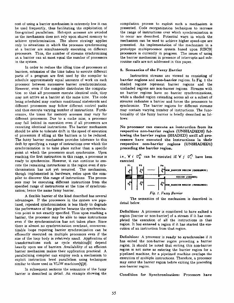
The advantage of allowing conditional and uncon- ditional branches is the possible inclusion of if- statements in barrier regions. As a result, the time spent in barrier regions can vary from one instruction stream to another. If a single instruction barrier region is used, all processors that execute the lesser number of
instructions have to wait. If the entire statement is part of the barrier region then there are situations where the variation in the number of instructions will not result in a stall. This is demonstrated by the example in Fig. 7. If a single instruction barrier is introduced at the end of the loop, the processor that takes the path along S, which involves less work, must wait for the other proces- sor before it can continue execution (Fig. 7(b)(i)). On the other hand if the entire if-statement is part of the bar- rier then even if the two processors take different paths they may not have to stall (Fig. 7(b)(ii)).
for (i-l; i<=N; i+t) do seq for (j-1; j<lz; j-f+) do par
1 Sl; if coed then S2 else S3;
1
Tark ‘: for ii,;‘; i<=N; i++) {
i if cond then S2 else s3; i barrier region ..l...~....--...~...........
1
Fig. 7(a). Parallel Loop with if-statements
(i) (ii)
Fig. 7(b). If Statements in Barrier Regions
7.2. Lexically Forward Dependences in Loops
Consider the schedules for processors containing dependences of the type shown in Fig. 8. These depen- dences point forward in the program source and are called lezically forward dependences(l71. Assuming that all processors proceed at the same rate, these depen- dences are satisfied by the time they are needed. Although the dependences are not likely to cause any delay, in an architecture where processors execute asyn- chronously, a barrier synchronization is required to guarantee these dependences.
The example in Fig. 9 demonstrates the use of a barrier to enforce lexically forward dependences. In this example the iterations of the inner loop can be executed in parallel and are distributed among four processors. Further assume that the outer loop has been unrolled once to create the tasks shown for each processor. Upon examining the schedules for the processors, dependences between statements Sj,, and Sj+,,l+, that belong to the corresponding iterations of the loop for processor 1 and
60

f+l are found. The outer loop contains loop carried data dependences; therefore a second barrier is intro- duced at the end of the loop to enforce these depen- dences.
The intermediate code after code reordering for the example presented is shown in Fig. 10. Upon exa- mining this code, it can be seen that the barrier regions for the loop contain a substantial number of instructions and hence the code is tolerant of significant drift in exe- cution of different streams. The code contains two dis- tinct barrier regions, one of which extends across loop iterations and the other is entirely included in a single iteration.
Fig. 8. Lezically Forward Dependences
for (j=l; j<l& j++) do seq for (id; i<& it+) do par {
Sj ;: a[j][i] - a[j-l][i-l] + i l j; 1 ’
Task T,, where 1 < 1 2 1: Private i; i-l; for (j=l; j<l& j+-2) do seq
1: S. : alj][i+alj-#-I] + i’j; b:‘krier; /’ due to lexically forward dependences l / s. : a[j+l][i]-a[j]~l] + i*(j+l); b:%r; /’ due to loop carried depeodences ‘/
1
- lexically forward dependenccs ----+ loop carried dependences
Fig. 9. Enforcing Lezically Forward Dependence8
/’ Let int l (10][4]; be the the declaration of the array and “a” be its base address l /
Non-barrier: e......
Barrier due to loop carried dependences: i-i j-1
Ll: Tl =i- 1 T2=j-1 T3=1a*T2 TI=T3+a TS-4*+1 Tb -T4 +TS /’ T6 <- address of a[j-l]li-l] l / T7-i*j T8-16*j TO-T8+a TlO=l’i Tll =TO +TlO /’ Tll <- address of a[#] l /
Non-barrier: T12 - IT61 +T7 IT111 = T12
/* T12 - a[j-ll[i-11 + i*j l / /* a[j][i] - T12 l /
Barrier due to lexically forward dependeoces: T13-i- 1 T14 = 16 * j TlS=T14+s Tl6 =4*Tt3 T17 - T15 + T16 /’ T17 <- address of a[j)\i-11 l / T18-j +l TlO - i * T18 /‘T19 = i*(j+l) */ T2Oj+l T21=16*‘IYO T22=T21+a T23=4*i T24=Tzz+T23 /* T24 <- address of alj+l][i] l /
----__----__-----_----------.-------------------*------ Non-barrier:
T% = (T17] + T10 [T24] - T2s
/’ T26 = a[j][i-l] + i*(j+l) l / /’ a[j+ll(il - T2S l /
Barrier due to loop carried dependences: j=j+2 if j<10 w to Ll
-_ -__-____-___________----------------------------- Non-barrier:
Fig. 10
7.3. Static Scheduling of Psrallel Loops
The schedule for execution of a parallel loop can be statically specified at compile-time if the number of loop iterations and the number of available processors are known at compile-time. It is not possible to distri- bute the iterations of a loop equally among the proces- sors if the number of iterations is not divisible by the number of processors available. For example, if there are only three processors available to execute the code seg- ment in Fig. 11(a), one of the processors would have to execute two iterations of the inner loop. As a result the other two processors may have to be kept idle for periods of time.
The idling times of processors can be potentially reduced in the following manner. As demonstrated in Fig. 11(b), instead of scheduling the extra iteration on the same processor every time, the processors can take turns in executing the extra iteration. The result of such scheduling strategy is that over multiple iterations of the outer loop, the processors do equal amount of work. Once the work has been equally divided among the pro cessors, an attempt to reorder code to create large bar-
61

rier regions can be made. In the best possible case, bar- rier regions large enough to potentially eliminate idling may be found (Fig. 11(c)). In order to achieve the above effect, not only must the inner loop unrolled completely but the outer loop must be unrolled as well. The outer loop is unrolled until the total number of loop iterations available becomes divisible by the number of processors. In the example presented unrolling the outer loop twice results in 12 iterations which is divisible by three, the number of processors. It should be noted that if the bar- rier mechanism was not flexible in nature, the compiler would have to decide how much code should be moved across the barrier in each of the streams. However, in this example all it had to do was to try and include as many instructions as possible in the barrier region.
for (j-l; j<lO; j++) do seq for (ill; i<b; ii+) do par
t loop body;
1
tb) (4
Fig. 11. Static Scheduling
7.4. Run-time Scheduling of Loop Iterations
In situations where the number of loop iterations and/or the number of processors available are not known at compile-time, compiler assisted run-time scheduling techniques can be used. Consider the code segment in Fig. 12. The number of iterations in the inner loop is not known at compile-time. Thus one must wait until run-time to schedule these iterations among the available processors. Several self-scheduling techniques have been developed to distribute the iterations at run- time(l81. Guided Self Scheduling (GSS) is one technique that attempts to distribute the work among the proces- sors so that they complete execution at about the same time[l9]. This is desirable as it will reduce the idling of processors at the barrier that must be introduced between iterations of the outer loop.
Idling of processors can also be reduced using the fuzzy barrier. At run-time the iterations can be distri- buted among the available processors. Next, depending upon the iteration being executed, the processor can choose to execute a version of the loop body compiled with or without a barrier. The successive iterations of the outer loop must be separated by a barrier for correct
execution. To achieve this, the first iteration of the inner loop that a processor executes should start with a bar- rier, the last iteration should be followed by a barrier and the intervening iterations should have no barriers at all. If the processor is allocated only a single iteration, the loop body should be compiled such that it is both preceded and followed by a barrier region. The four ver- sions of the loop are shown in Fig. 12. Compiling multi- ple versions of code and selecting the appropriate one at run-time is a common practice in parallelizing com- pilers[20].
for (i-l; i<N, i++) do seg for (j=l; j<M; j-t-t) do par {
loop body; 1
Task where l<p<s:
for $i-1; i<N; i++) for (j-p; i<M; H-S) {
if j is (first and (not last)) iteration { oersionl } else if j is ((not first) and last) iteration { aersiona} else if j is notffirst or last) iteration
else if j is (first and last) { versions }
iteration
1
{ ocrvion4}
Fig. 12. Run-time Scheduling of Parallel Loops
8. Preliminary Results
Commercial muitiprocessor systems, such as Encore[l4] and Sequent[lS], support the barrier mechan- ism as part of their parallel programming library which is available to application programmers. By supporting the fuzzy barrier in software, the performance of the sys- tem can be further enhanced. A software implementation of the fuzzy barrier on a four processor Encore Multimax has been carried out. For nested loops, similar to those in Fig. 9, the cost of synchronizing four processors was reduced from 10,OOO~sec to 3OOpsec as the size of the barrier region was increased from zero instructions to half of the total instructions in the loop body. The cost of barrier synchronization is mainly due to context saves and restores for the tasks that must be stalled. As the size of the barrier region increases, the likelihood of a processor stalling decreases. Therefore, the expensive context saves and restores may be avoided. At source level a programmer may be able to construct barrier regions while coding an application. Thus, it is possible for both the compiler and the programmers to exploit the semantics of the fuzzy barrier.
9. Current Status and Future Work
The fuzzy barrier mechanism is being imple- mented in a prototype system using RISC processors. It will be used for executing code in VLIW mode as well as
62

code generated by concurrentization of loops. Currently the possibilities of allowing procedure calls from barrier regions are being investigated. This is important because allowing parallel procedure calls can significantly increase the amount of parallelism. The issue of interrupts and traps in a barrier region is also being investigated. Traps are useful as they are often used in RISC based systems to implement floating point operations.
Acknowledgements - I am grateful to Mike Epstein for developing the first hardware realization of the fuzzy barrier and to Carlo Bronco for assisting him. I thank Mike Whelan, Charlie Hill, Mark Tucker, Jim Wendorf and H-Y. Wang for their help and discussions during this work. I am grateful to Horst Mauersberg and Loek Nij- man for their encouragement and support. I appreciate and thank the referees and Prof. M.L. Soffa for their suggestions.
References
1.
2.
3.
4.
5.
6.
7.
8.
9.
10.
P. Tang and P.C. Yew, “Processor Self-Scheduling for Multiple-Nested Parallel Loops,” Proc. Inter- national Conf. on Parallel Processing, pp. 528-535, August, 1986.
R. Gupta, “Synchronization and Communication Costs of Loop Partitioning on Shared-Memory Multiprocessor Systems,” Tech. Report TR-88419, Philips Laboratories, Briarcliff Manor, NY, 1988.
H.S. Stone, High-Performance Computer Architec- ture, Addison-Wesley Publishing Company, 1987.
P.C. Yew, N.F. Tzeng, and D.H. Lawrie, “Distri- buting Hot-Spot Addressing in Large Scale Muf- tiprocessors,” IEEE Trans. on Computers, vol. C- 36, no. 4, Aprif, 1987.
C.D. Polychronopoulos, “Compiler Optimizations for Enhancing Parallelism and Their Impact on Architecture Design,” IEEE Trans. on Computers, vol. 37, no. 8, pp. 991-1004, August, 1988.
J.R. Ellis, Bulldog: A Compiler for VLIW Architec- tures, MIT Press, 1986.
R. Gupta, “A Reconfigurable LIW Architecture and its Compiler,” Dept. of Computer Science; Ph.D. dissertation, Tech. Report 87-3, University of Pittsburgh , August, 1987.
R. Gupta and M.L. Soffa, “A Reconfigurable LIW Architecture,” Proc. of the International Conf. on Parallel Processing, pp. 893-900, August, 1987.
D.A. Patterson, “Reduced Instruction Set Com- puters,” Communications of the ACM, vol. 28, no. 1, pp. 8-21, Jan., 1985.
A.V. Aho, R. Sethi, and J.D. Ullman, Compilers: Principles, Techniques, and Tools, Addison-Wesley, 1986.
11.
12.
13.
14.
15.
16.
17.
18.
19.
20.
J. Hennessy and T. Gross, “Postpass Code Optim- ization of Pipeline Constraints,“ ACM Trans. on Programming Languages and Systems, vol. 3, no. 5, pp. 422-448, 1983.
W.C. Hsu, “Register Allocation and Code Schedul- ing for Load/Store Architectures,” Dept. of Com- puter Science; Ph.D. dissertation, University of Wisconsin, Madison, 1987.
D.J Kuck, R.H. Kuhn, D.A. Padua, B. Leasure, and M. Wolfe, “Dependence Graphs and Compiler Optimizations,” 8th Annual ACM Symp. on Princi- ples of Programming Languages, pp. 207-218, 1981.
“Multimax Technical Summary,” Encore Com- puter Corporation, Marlboro MA, 1987.
A. Osterhaug, “Guide to Parallel Programming on Sequent Computer Systems,” Sequent Computer Systems, Inc., Beaverton, Oregan, 1987.
R. Gupta and M. Epstein, “Achieving Low Cost Synchronization in a Multiprocessor System,” Phi- lips Laboratories; Tech. Note TN-88-140, Briarcliff Manor, NY, October, 1988.
R. Cytron, “Doacross: Beyond Vectorization for Multiprocessors,” Proc. International Conf. on Parallel Processing, pp. 836-844, August, 1986.
C.D. Polychronopoulos, D.J. Kuck, and D.A. Padua, “Execution of Parallel Loops on Parallel Processor Systems,” Proc. International Conf on Parallel Processing, pp. 235-242, August, 1986.
C.D. Polychronopoulos and D.J. Kuck, “Guided Self-Scheduling: A Practical Scheduling Scheme for Parallel Supercomputers,” IEEE Trans. on Computers, vol. C-36, no. 12, pp. 1425-1439, Dec., 1987.
M. Byler, J.R.B. Davies, C. Huson, B. Leasure, and M. Wolfe, “Multiple Version Loops,” International Conf. on Parallel Processing, pp. 312-318, August, 1987.
63