the general r a d i 0 - ietlabs.com · r-r measurements of the equivalent-circuit parameters of...
TRANSCRIPT

THE GENERAL R A D I 0
r
.. VOLUME 34 No s. 7&8 JULY-AUGUST , 1960
IET LABS, Inc in the GenRad tradition
534 Main Street, Westbury, NY 11590 www.ietlabs.com
TEL: (516) 334-5959 • (800) 899-8438 • FAX: (516) 334-5988

COVER
In R"yl".Dn', S.mlconduclor AdvDnc.d D.v.lop.... nllDborDIDry', Willi ..... f. M .. IDn.y, Engl .... ri .. g A .... 1100 .. nl hchnlcol, .... O.Ur .. ,unn.l_diod. pDrD .... '.n wi,h Ih. G.n .. DI R .. di .. T .......... funcliDn .. nd Im... IIIon •• Brldg •. I .. u' .hDw, cI"aill 01 <00,,101 ..... unl.
THE GENERA L R A 0 I 0
fxr fR IMfNTfR C I960-GfNUll RUIO COMPANY, WlST CONCOID, MASS., U.s.A.
Published Monthly by the General Radio Company VOLUME 34 • NUMBERS 7 & 8 JULY.AUGUST, 1960
CONTENTS Measurements of the Equivalent·Circuit Parameters af
Tunnel Diodes............................... 3 The Use of the General Radia Immillance Bridge in
Tunnel·Diode Measurements.................... 9 Welton, 1960 ..........•...........•......... 12
The General Radio EXPERIMENTER is moiled without charge eoch month 10 engineef5, scientists, technicians, and others interested in electronic techniques in measurement. When sending requests lor subscriptions and address·chonge notices, pleose supply the following information: nome, campany address, type of business company is engaged trI,
cmd tille or posi/ian of individual.
GENERAL RADIO COMPANY Wes/ Concord, M055C1chusetts
Tll'lotph .. "., IConcord) EM."on 9·4"'00, IBo.,on) Ctecr.wolD' 9· 8900
N~W YORK: e. .. ad A .... nu. at l ind.n, Ridg.fI.ld, N.w J . ... ,
CHICAGO:
PHILADElPHIA:
Teleph" ... - N. Y., WOrlh ... ·2722 N. J., WH"MY 3 ·3J40
6605 W.o' North Av."u., Oak Pa.k. IIII"Di. T.,.ph ..... - VWago 8·9 ... 00 1150 Yo", Road, AbingtDn, p.n .. ly ..... nl .. f.l.pho ... -HA"<o<~ ... ·7 .... 9
WASHINGTON: lOSS 13th 51" Sil" •• Spring, MD.yl .... d fel.ph ..... -JUnipo.5·1088
lOS ANGELES, '000 NDrth S.w".d St., lDI A"g • ••• ll. CD'i'. T.I.pllon. HOllywoDd 9·6201
SAN fRANCISCO: 1 '16lD. AhDI Av •. , lOI AlIol . CDIif.
CA NAO A,
EAST COAST:
NEW YORK:
MIDWfST,
WUT COAST:
CANADA:
ToIotpho ... - WHiled,ff 8 ·8233 99 f'ClfDI p ... kw .. y, TClfDn!o 15. OnloriD TlllephD'" - CH.rry 6·2171
REPAIR SERVICES
G ..... "I Rodlo CD" S • • vl .. D.pl" 22 BDker Av enu., Wu, C .. n~D.d. M,,".
TIII.ph..... C"n< .... d, EM.r ... " 9· ...... 00 B",ton, Cteo.w .. I •• 9·8900
G." .... I R .. dlo CD., S .. vi.. D.pl.. fl.rDod Av. . at l lnd,n, Ridg.fI.ld, N,w J .... V
T.I.phone- N. Y., WOrth .·2722 N. I., WHot ... y 3·3''''0
G.n •• al R .. dio Co" S ..... ic. D.pt" 6605 W •• t North Av." Ook p ... k, tltinDi.
T.I<rph .. n. - VW .. ". 8 · 9.00 Gen.r .. 1 Rod;D CD., S •• vl •• 0.1". , 1000 NDr/h S.w"rd
Sit ... , lDI A .. g.'.1 31. Colif . TeI.phD ... - HOllyw .. od 9 .6201 S .. yly ~"gin .. rlng , lid. , FifOl 5 •.• Alo •• 0" .... 10 fel.ph ..... - Tot .. nlo EMpi,. 2· 37""
IET LABS, Inc in the GenRad tradition
534 Main Street, Westbury, NY 11590 www.ietlabs.com
TEL: (516) 334-5959 • (800) 899-8438 • FAX: (516) 334-5988

r-
r
MEASUREMENTS OF THE EQUIVALENT-CIRCUIT PARAMETERS OF TUNNEL DIODES
The nlcu.surcmcnt of equivalent-circuit parumClCt"S is of particular importance in the development of semiconductor dcvicCl;, in the: control of their uniformity in manufacture, Rne! ill their application ill pr:lc!icnJ ci rmils. Tu nnel diodes Iwcscnt unusual measurement problems, both because of tbeir um~tflh tc
behavior in the measuring circuit undel' (:{,l'taill bias conditiolls !tnu becallse some of the characteristics to be InC3.stll'l.:d tlrc HoI dil'ccctiy accessible for mClIsllt'cmcnt ;\1 the diode terminals. TheS(' problems, top:cl her \\ ilh sugges tions for 1 heir 8Otu!irm, will be discussed in Ihis udieJc.
i\Jt'!tsurcmcnts IIrc most cOllveniently made in 1 he "hf-uhf rnngcs. Kot Dilly do the high·fnxllIcllcy characteristics give the best index of perform:mce for pr!lcti(·:llIy all applications, but also the measuring instruments nnd circuits H\·ailublc nt these frequencies ofTer the advantages of complete shielding and fr(X'dom from residual impedances that are characteristic of low-impedance (!Q!lxial systems.
TUNNel-DIODE CHARACTERISTICS
The cUt"l"cllt-voitage I·clation for the tUl1nel diodc is shown ill Figure L :\nd Figure 2 is an equin1lcllt circuit. As is evident from Figure 1, the diode:lc n .. '-
Fig" •• 1. C""..nl . ... ol!o l! • • ho,o ... , ll.l. of a ,,,"n _1 diode.
1m.
sist:uH'C, H, is a function of bias and can be either posit ive 01· n{'gativc. The carP:\CitllTlce, C, Fil!;w"c 2, is also II fUilCtiOll of hias, but cha nges more gradually. The smnll-sign:ll ac characteristics of the diode are described in terms of the equivalent-circuit pammeters, L. C, H, and R~ aud of cedain ehnractcristie frequencies that a1'(' iUlwtiollS of these values, and which arc usually defined in terms of operation in the region of milliUlum ncg:Ltin' resistunce. These frequencics :lrc the sclf-l"cr;onant frequency, w!tere the immi t lance of the diode is purely real, and the resistive cut-off frequency, where the immittallce of tbe diode is purely imagin:lry, represcnting the upper frequency limit for diode negative resistance. A third chamctcristic rrC<jUCncy sometimes referred to is the oscillation frequcncy , which, by definilion , is 1\ worctically the frequcncy at which the diodc wiU oscillate if short.c.in"llit.cd . In pmctice, the amplitude of this oscillation will be grcttt enough to swi llg over the nonlinenr region of the diode rcsistance and capncilnl1ce chu.1"tlct.cristics, EO that the frequency of oscil1ation may not correfSpo11d to the true smull-signal oscillution frequency.
STABILITY CONSIDERATIONS
In the mensuremellt of these q\I:Ulti-1 ies as well as in practieal application of
Flgu,. 2. Eq" l ... ol en' circ uli 010 ',,"n.1 d lod. {Inold e do ll ed , . <longle ), with . h ,,"tl ng , •• ,010'. Rp, which
.Iobil, ... o~,o' ion In a meoo".lng clnult .
r---------- ----, I L R I
~_~_,""",~ I
200 300 400 : Hci H Em. L ___________ J
IET LABS, Inc in the GenRad tradition
534 Main Street, Westbury, NY 11590 www.ietlabs.com
TEL: (516) 334-5959 • (800) 899-8438 • FAX: (516) 334-5988

GENERAL RADIO EXPERIMENTER
t.he diode, n IIUTl\bm' of precautions nrc neccs.~lry, owing to the negativc-resistnm:c, non linear, and multivahu,.'d~UI'
rent ehnrneteristics of tunnel diodes, A shunt resislnl1CC, R", is gCII(' rnlly required for staule operation, A specific choice of total c.ir('uit resist:;lIlce is UL'Ct-'S
sary for stubility. ~cveral modes of operation that depenll upon tlll1> t'llUite are shown gmphically ill Figur'c 3 M a function of the impcdnllcl', lir, \Ihich is the sum of the diode rcsi,;,tfillCt!, HI' amllhc oqUi\·tllcnt source I'c~ istnnr (' , R ~. T he cQuivakut. 8Our(,I' 1'1'8i813,nee is, for aCt
die shunt resistance. HI" in pnmlld with tbe signll.l-Mun.:c I'L'l'i~l!lIlcc. For £Ie, R~ is il l' in pll.rnlll'l Wil h the d t" source res istum'c, If the de rLl'('llit. rC!ij,.;tancc of RT is greater Hum lhc 1ll'lZativc-I't'Sistance mll.gniludc, Ht operation will be unstabl(' in the IH:gnlivc-l'csist:m{'e region. In Figure I, RT is large compared with the IIcgative I'CI'istll.nce, und, M tbe bias \'olta~e is incrl':u;e(I, tbe opt'rating point of til(' diode will switch from A to J1, If the bias v(}1ia.l(c ;s thell decl'eased, the opera.ting point will swii ch b3Ck from C to /J. 1£ Rr is IC!'!! than lhe negative rcsistance, no switching lI'i ll occu r. ]f t.be .nc I'csistallcc of R T is less than
R~ I the circuit will oscillate.
In the T HE 1(107-.\ Transfer-Function a nd [mlllit t:UH'C Bridge, fo r example, thc efTectivc de source msistance is the dr-hin... .... supply illtemal r~isl!lnce. in series \\ith the biIlR-fil!l'I' I'e~istnllce of 4 ohms , The au SOUI'CO impedance at hijth fm,llIcllcics i~ IIppro:.imttt l' ly no ohms at the ol){'ratill(!: froquelley. AI other frequellcies the im rx.'dullcc may d itTer from 50 ohm!;, but will usuall,Y euu$(l IlO diffl('ulty if the s.hunt, resistor is no ohms or 1f!SS.
•
STABl.E REGION
flg .. r. 3. Mod .. of o pe rotion for ,h . 'unnel diode os o f .. ncl;on of ,h. '0101 c;rculi , .. Itlonn, /P"
will \'allil'h if lhe induct:tlli'e J.J is greater th:m n2c. Wit h IllOS t, currently ovni lnble tunnel diodNl, the p:u::kagc-and-holdcr induClti nce is small enough to permit stltble opel'll ! iOIl. Since low-imped:1Ilce diodf'S a re IlccL'Ssnrily rh.'signed with low pal'asitic indIlCI!lIlCL'Ii. the total circuit induct:lllce betWC('1l t he diode und t he C<lui\'alellt source rL'si~t:Ulce H~ must. be exceedingly small. This is possible oll ly in cn.refllllr de~ign~xl mOlillts.
I n t hc preccding 1l.1ut.lysis the sourcc impedance is ass.umed to be purely resis tive. In most, prnciicn l appl ic:ttions this condil io!! will not be ex:lCUy met, nnd til{' ltl'tu:tl ol>cr:H ing cha.rft("tcristics will ditTer somewha t fro m those outlincd above. In :Lctu:tl me:llmrc:mellt s, ill Ule Ilegativc I'CliiSlnncc rep.-ion , the bes t results have been obtll.ined whclI the rcsi;;t,U1ce of Ihe ;;hull t resistor itself is slightly lowel' ihun the minimum ncg:l.tivu I'CSist;U1Nl of the diode.
As a further pr('Ct\utioll, bcx:ausc the diode Ch:lruclf'rist ic is Ilonlin(';l l' , the amplitllde of the sign:ll in cident 011 the diode must be sm ull. For I he diode shuwn in Figure I, n value of n fell' mill ivol t~, nus, is n reasonahle upper limit for smnll -~ignal mell.<m rcmcnt s, Further, if fl. slI!H'rheterod,,{llc !lull detector is employed in t he briel/(' mC3surcmCllts, locnl-oscillntor le:lkaf.!:(' ill to the tUllllcldiode circuit must not. exceed a few millivolts,
DIODE TEST MOUNTS
r.. The test mOUllt for t he diode must be Thcstnbll' l'cgiondefincd by He < HT< R designed to minimize stray induotunce
IET LABS, Inc in the GenRad tradition
534 Main Street, Westbury, NY 11590 www.ietlabs.com
TEL: (516) 334-5959 • (800) 899-8438 • FAX: (516) 334-5988

, Fig",. 4. S"IIII"'od co .. :I11 ... ........ "t f .... ~onn .. !lnll a '"n .. ol diad. InlO tho ... oolu,I"1I 01 .... cull .
RESISTIVE COATING ON THIS SlOt
JUl Y . ... U GU S T. 1960
-874_6146
r ~r
~62 0
L------1 1-_ .....1 .2440 .786
1
-I.D!>?
flo , mounl . hown h ... li d, . , 11I"od 10' tho ",,1'1' ho~1 dlod o ......... h ....... d by So "y, ""hid. hal .. 11"1110 I, .. d . ,. dlfl.,o .. ! .. ,. ronll . .... "1 b dou,i ... d In 110' ...... lid o by "dl,. ond Wont on (pog ' 9 ) and II d .. lg .. od I. 0«01'1 110, Roylt."," CK40 type , which II In a ",let'1>w .. ". di"d, pa<~all" 010.1 .. will, Iwo lo .. d . pr ..... ! .. ... 0.' dilnc,,11 problo ... Ii nc. lilt m .. unt ",u. 1 b , do.llI"od 10 ,"ceoI" ,10, g •• u"d lo.d. Fo ..... .. . -... t ... t .. 1 purpo . ... 110, ".,d .an be '0"'0 ... 01, bul 1101. I, hardly .. ",ocl;e.,1 p!'oct.h.r. 10' d,,,,lo p"'o"'O' o nd ",o.h.cllo .. ,uling.
nnd capacitance, particularly if lhe diotic rcsist:lIlc(', H, i::; low. MeaslLI"l'mcnt :u;cumcy is impt'ovcd if t he ShllUIr in~ resistor is located tlS dose to the diode lIS possible, as shown in n su!!:gestN.1 CO{L"ial mount. ill F"ip;UI"e -t. This resifltor :<hould be lower tllllll the ncgnlh'c resi.'IhIlH:e of t he diode under t($t, be esS(·nlially noninductivc, and have n Jlep;lig-iblc shunt ca pacilallce. In cOllxial syRtcms film- I,ype disk rcsisto l's ,ll"e f'lIit ... able. T he el~,t l" il':d lcn~t h of the cOilxini mount. showlI in Figure -' is equnl to that. of the Ccncml Bad ia Tn'li: S/4-WX3 Short-Circuit. Tcnninatioll.
If n. measurcmcl1L of the diode cap:wittUlCf' flJld indw·t:Ulcc outside th e llf'P;!\
tive resistfln l"eregioll isdesired , theshllntilll!; resistor is Hot nc('(.'SSUry to ohtai n st."lblc operation and can be omiUed.
CHARACTERISTIC EOUATIONS
The diod(' ndlJli1tI1I\~·t' .lnd imlo('(inllC(' in b'rm" <)f III<" cirruit 1'1.'nWIlt$ of th.· ''(lui v:,I!·nl \: ,rl' uit , FI~lIl'(' 2, tire
AdmitlallCC a. _
\ _ U. [I + (wf'H)l] , /I
- /I '(-'--"'-U-'_'I:: ) ~ +(~:.) ~( I - If/-;t'f (I
/I, " N. - 1 + lw('J( )~ (3
. [ /1'('] ,x. - w IJ -I + (w('H)~ (I
111 tiw,,' ''(llIntl''h~ If i~ 1l."'"'lInwd tf] I ... III !Cath·t,. ulld nu IItiditiurml lw~ati\"l' ~I~' ,h"ul<l IH' 11-.1'11.
CHARACTERISTIC FREOUINCIU
S.·lf·n,,.mm,,l rn~ll"'l'ry
I.
I.,
, '--" ,,-" 2, \ lA' \ I - /(~('
It _ 1 N.
I It. 2r ,/,C \ I - ft:
(.1
(II
(7
l'YJlienl dil'd .. immiu:ult_frI'q1l1'1Il")" ehurIIct"rj"lil'~ tin' ",/"1\\'11 in Figul\'" 6 :lIId Ii, fur
I. Il~ <; r ('.'(tl'- lll lUiI'll,," n.
Silllplifi!'!ll ihll of tll'" .... f'xprf'_'~i"n~ i~ rf'{lIlil'(-d, il\ gt'lwrui. ttl n·I:I!t, the UJIk""wn 'llmntlty ttl he mru,,,ul't'(l t .. Ih,· al'tu;\l ml11<'nrnj VIIIIII'. r.h':I.!;l.Il'l'lIwnl frt'qu""~Y Ilfld op"rnling hi,..., fr,n\"tlrd Zlnd n· ... ·M'. 1IlU,--t h,· "" 1"1)1 ..... 1\ ,~. \.)
pl.·rmit Ihi~ ~im l)l;fi,.,!.ti ... n. Til.· rh"jrf' "f ,,"', .... uring ("1111.1 111"11,, ill furth.·r n·,lrWI.,lloy 1110':. ....... urin~-i n,!;trllnwllt rl·""lution. With """'" di'Hlh, in ]ll\rtil'ttllir t(l1Il\' KlIliul1l-""""nid,' IYII''I<, Ih,' I'implifi rHI i(\],,~ JO',.(\ to only ap[)r",<irnnt.· "nhll's for t ht.' uukn\lwll qU::II,\il i('~. r!"g"rdlt·"" t,f "I",rutit'i!: ,~ ltIditili ll" a"d 1ll("~urin~.in.,lrulll1""t 1U'f'urIlC·Y·
IET LABS, Inc in the GenRad tradition
534 Main Street, Westbury, NY 11590 www.ietlabs.com
TEL: (516) 334-5959 • (800) 899-8438 • FAX: (516) 334-5988
GENEIlAl IlADIO EXPERIMENTEIl
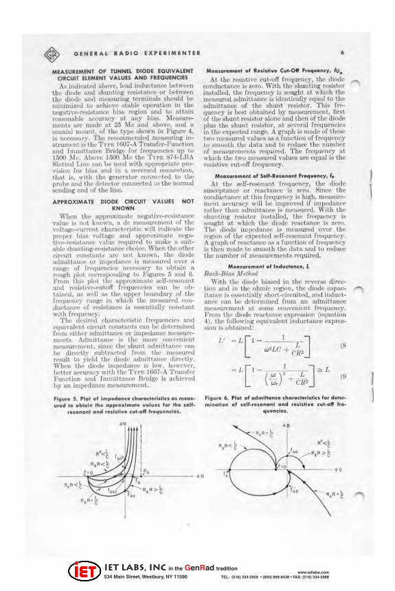
MEASUREM ENT OF TUNNU DIODE EQUIVAUNT CIRCUIT ElEMENT VALU ES AND fUQUENCIES
. .u indil!lIlA'd liboVI', 1£'nd indurlllnoo lI£'tWl'e1l thr diode lind ,,1mutlng rcsi.sl 'LJI~~ or lwt lrt't'll lIll' dil'lJ(> find ffit:lI.'!lIrilig terminals should hi! minimi:u-'d t() at'hi~"£' ~tnbie op<'Tatioli ill the nl'gllll\'e-r,""i:"t:UlC(" bi!l.b rx-glOIi llnd W attain T('AAOIHlhll! IIC{lUrlU;y "I lilly uina. 1\le6.'!uremenb llJ"I' mnd<' at 25 Me ,m(1 1100"1.-', und '" (orunll \ mOIlIll, of t h,' type "hm.'n in Figull.! 4, i~ Ilt~.rv. The n.'<'OUlllwnrif,(\ lIleMurUlg ill~ ~tnum. lit i~ th!' TH.; 1 OOi-A Trtuu,f"r-Fullf't ion Ilnd ImlUittnnce Brirlg" for rr<'(lllenci('t! 111". 1 ~1 ~!.'. Above 1500 1\1<:' thl.' 1 nf: ~i4- ~IlA Slot\oo Linl! can be u~1'd with nVI'roprint{· 11K>vbioll f(lr hhll anti in II. rl!\'ellll'd oonuf'rlif>l1, tbllt i$, w,th thl' genrrLltor t .... 1Ullell:d 10 t ilt: probe "'lid th,' d<'tl'etor connected .0 thl' uorfill! ecnding £'lId (If til£' line.
APPROXtMATE DIODE CIRCUIT VAL UE S NO T KNOWN
" 'II"n th l! npproxim,I\(I lIt:gntivt~"",i~llmN.' "llltlf' i~ not known. 'l df' m£,II./iUN' nwul uf Ih.· \·olt:'~'-!·'I.I"I"('nt dlllrLId"ri~tic will indkull' the 1)I"I"",r billl! vnJtng<-, nnd "11lln))I'imatl' 1I1'~:"" tiVl~~i~ttUH'f' v:uur' I'('quil"l'tl to LIIttkl' II <lUIIahl(' ~huntin/l;-r>"'i~l>""l't· cook ... ·. Whcn Ihl' 01 hl'f eir","1 ro'l.~tIU.t;i 111"1.' not km,wn, till' diode u,hniti:IIl('I' or inll"''(llInl~' i~ 1Il1'!lsuroo:i uVl!r II r:mg" of fr.'<]Ut·ncil'tl IlI·t .... 'i<lIry t() oLI:l.in A r"ugh "h,t l .... rr£'.bj.Mlllding tIJ FiJ(lI~ 5 Hnd 6. From thi~ I'lot till' f1/IIH'()XinlHtl.' !>l'lf-N".01UlTlt Wid r • .,.i~tl\""-f'lltoff r<-'que'H'll'l! 1'1\11 h" "hUlinr'{l, I\i:I w,'l! WI Ih.' UPI)(.'r houndary of thc fn'qll"ncy rll1Jge hI whirh 1I1l' ffit'IioiIlJ't'(i 1'01fI
dUct:'''l'l.' or re;i!;1.:tllOO iii esscUli:l.liy C<.J11.:!t.unt With frt.'t/Ul'lIty ,
TIlt! I ;'~il1'iI ehar,lttl'rbti(' fn'qlL£'lleil"lI and l'Quivnll·nt dr"uit ('(",stllnts C:\n II{' d£'lt'rrninl'(l frum elUu.'r ttdrnittnn{'(' or imp.'(lunl"l! Dll·!O>'.un" mt:nL'I, Adm,Unnl't' I~ t lU' murt' ('01II'(llIj",,1 mtll;lUIl'm('lll., lIim'" Ihe Khun! n,dmiUII1H'" ~Iu\ be dircttlv ~ uhtr:.L('t,'d frum the IlWJ ... lI!"1'd fl"llIlt to yi(lld Ih,' tii':kll' lldmlltnncc dirl'£'tty. Wh£'o tbe diodl' i",IX'(\:tUC(! (~ 1o\\" huw.'vl'r, b>'lIer lW'eurn('Y with lilt' 'fl'I'.: lOOi-A Tr'II.~f(-'r Funclioll nnd immit\::Llll'C Bridge is nchi£,vt'(\ by IUl impcdnut:e ml'tl.\;uremeut.
fig .. r. 5 . Pial of i",~don .. charoc •• • ll li .. 01 ""01' .... d 10 oblaln Ih. opprod",o' ... 01 .... for 'h , •• If_
... 0"0"' o .. d r .. loti .. , c .. I_a " 1 ...... . ... 1 .. .
., I I I I I
R'<~ I 'to' I
R.R<~ I ., I.RI
• M. a . .... "' . ... of 1t .. I.li ... Cvl-O" F ......... cy. IG.
At t he I'I':!ibln'e cu l-off fl'l.'<]ueney. the diode (!Onduct ,'IUX' is zero. With thl' ~h \lnti"R regj~lor in811111t:d, thl! fn'llucl1cy is !!Ought ~t ",hidl t he nl"nsurl-'d admittKn~ is idclltieruly cqulilio t h£' nrlmittnnoo of the ~hunt Tf'i;i'ltor. T his freqU(lncy ill best obt,tinl'd by ml'!~urcml'''t, fir~t of t he ~hunt r<'l'Oi~ tor ll.lont: lind tht:n of th!' diOOe pIt/.!! t h~ shunt rC!:li ~wt , :.t lIt'v£'r :.L1 frl'Qul! uci.'s ill the \';t"pt"Cted rIUlgt:', A gr.IJlh is nmdl! of thl,*, Iwo m(-'lIlIurf>(i valul'S as n f1111(·ti01l o f freq uc lI(:Y 10 SI11Qt) th the data nnu to r~duC('! t llll lLl unj,l'r of IlWu,SlIrenll'lIU; required , The fl"{'(ll .. 'Iley ZIt whi£'h thO.' two mCMlIrNl vnluC8 nrc cqunl is the re.;istivl! cu L-off fn'qllcney.
M.o ... "", ... 1 01 S.II_R .. ananl F .......... y, I. At the ill'lf-re.;olla,nt fl'('quO.'l1cy, t he diode
Bltse{'ptnlloo or re.-u:lllllt'C is 1-£'ro, SiTlC"C th£' rondU('l:lure al thii! frl-'Ql1l.'lIry is hiRh. nl!.'1\SlIn~ nU.' lIt n,'cu nwy will be impro\'t'ti if impt"'(\:l.JlI·{\ tulhl'r tlinn :ldmittlUlCI' is m.'n;;uT{'\j. W ith thl! "hunting ~bl()r in~t!I.ll ... I, t he fl"l'tJ1It'nr)' ii!L "'}lIKht nt whieh the diodt, l'l.'UcllUlC(' i ... zern. 1'111' diod e inlP''l.illllt..-: is mC:"~lI red (wer till-' r"(l:iou of t htl cxpccll..: l l'I' lf-n'I.,m:.LIlL fn..'<IUCI1f'Y. A I'mph of ~:lCt"nl!!.' l\.!I:t flu .ttion of fro'qu£'Il('y it> then Inll(le to t>l1looth Ih(' (111111 and 10 n..-dUt"C the lIumber uf IUI!I\!jUl'C'TlWllts r{'Q ui n..'(\ ,
M. os .. "",."' 01 I,,"uc'an .. , L Buck,-8iu~ .IUd/lOa
Wilh lilt' d iodr hi:L.SCd ill Ih£' rtV1.-'1'*l direction and ill t he ohmk r" guln, t im diode 1)1Ip'.cit.nll('(' is ........ ·1l1inUy ~hort-drcuited , :l1Id indud:UI('(' t:UI he c\t<tl'tmined from an tldmitt:moo IIl1'1o.$(lI"{'IlWnt fit :<ume (!OI1Uenil'Ilt fr1'quel1cy, Fnlln th,' diQ(\e I'l.·UI't:lIl("(· cxpr".-,;;t)1I (t'fjUlltinn 4), tlil' f/)lIowin~ Nluivah:llt indUctw'(:e cXPn..'1tliion i.'l ohtwntXI :
- L [ I-~ I -J '" I. w ~ I~
( "") + el l'
(8
(U
f ig .. ,. 6. 1'101 of a ..... inane. charaett,i.lI" fat d . , .. _ ",Inalio .. of .. 1/_."0 .. 0,,,. 0 ....... illi ... c,,'_all' , •• _
.... . .. ci .. .
••
t \
I \
IET LABS, Inc in the GenRad tradition
534 Main Street, Westbury, NY 11590 www.ietlabs.com
TEL: (516) 334-5959 • (800) 899-8438 • FAX: (516) 334-5988

, whrre
/1 - th(' inducll1l1f'(" \·11..111(' mcMoUrOO
1 w,. - vLC
TIlt' diode <''' I>tIcitnllt'e, C, i~, ill thi~ CIL'tC, ~Iighlly lower thl1l1 it. i., in th .. negnti .... ~rC!li~ !I.llce ",ginn.
oinf'e the second h,rlll ill the l'xoct C!Cpl'l~ion iucludt'>:l tbe unknown, I., il mu.s' I)I.! ~l1l:1lt. or Iht! ('tror in thi.'l npprm:im"tion will I .... large.
When ct~ is IlUflieiNltly larg.} (and thi!! AB-
611llH'8 tllllt *' is knvwn II11Proximatdy), the
mCllllUl1'mrnt fl't'qupn{'\' ..:hnice is not criticn!' In ord('r to rt:'dU(l' this term to lOr;(, o r leN,
tben.lltlo\\'rrf'qll('nci('1l(wh('re(:r)~ < C~), L
It must 00 I~ Ihlln 0.31:
Thi~ l'I..,<!uircmclII Is nWI in most diod~ ... ,
wh.·re typical vlllu~'~ ar/' f. ... 100, f( - L A
nominal low fn·q'l"n ... y clwi loe would he' :looul or", fourt!. the sdf'l'(""mullt frcqut:II('Y, / •. T h.., _hunt rt'tlistor is l\(It roquin.'tl in thi.'! nll~:""lIn'm.:nt.
Olflllm/J-Dir>lu M elh".l SlU(,(, th.-' diode inullctnm:e is princil'ldly 111
til{' ronllccting leud 10 ,Ill' 8('rniCOllduct"r dl-~ 111<'lIt, nil ('<I \l i\'al~nt \U\Ckllgl' I'/ln be [nnd l' with Ill!' .·I .. ment n'l'hl<"l'l by II .. hort-cirl·uit. T he intl\lC1Ulll~ of thi,; Jl'l('k[l~(' C:11l be m r':I:lUreU ",thuut the IIU(WIl I"CIItrlctlQu.;; 011 f["{'quem:y.
eo,....''''n .. M_.u, . .... n!
'I'll(' (hoof' 1':lp"('llnl1('(' C1UI be direc1ly mf':VOun't!1l11\ frt.'(lucncy lld(,(\\llltd~' below the I!O'lfn~lIllnt frt.'qul·ncy. T li~ Cllpat;itanl'C elm l,-,u,\lly be me~url'(l ill the neg:.tivc Il.'!!istllllce I"(,.ltiun, :lIthuugh in~trunlPnt crronl find errors fm lll diodf' indw·l"n(1.' nnd rt."isllllll"e CIIII be ... ·riQlI~. The frt.'Qucn~y lind diodc IlC ll'8i;!ttUlce lilllitlltiullin/"(' ,It followlI:
From thc diode 5Ul1l"ell tnnce cxprCi!!1ion (eqUiltion 2),
Wltl're C' _ IIPI~\relit rllp,o.c.il,mC(! ~ n1l'z\lt\l1"t:d.
The rigbt~ llI.lIld tf'tlll thl'f"Cfore should I ... !1~lId.' UI be nl'lIr unity f(lr m~'(i!",lum lI(:(:\lr"I'),. I h,· lin,t ~11'p to ,,,,luI'\'" t lus IS to 10",I'r lilt:
n\('!ll:Iun'nll'llt frl'(Jlu:tll·Y. If Ihl' CUIl'lcitll.lLl'C i~ tu be ml!lIllUI"l,(/W within 10 %. then
1 . ("'«8-'1 fWllllllUlII; 1Iml /f'J> ", .r.:
JULY _AUGUST , 1960
If the ml'llO'UM:ment fnxJuency ill w~n ix'iow this limit (it tiJl<)ulti JlOL be so low t hilt UU~ CIIJllli.:illUI<:e s\l.o,c('ptnlloo is oolllpar:llole to illstrument n'llOl ul ion), the mcu.;;urt-d ClIIU.\'il:l.Il00 I"tldUl't'S to
C' - C[I-r~l~J W),l·n Ir >":> R.
It i.!; R9!umt'tl that the (hoo .. rin'uil pn.rfUll_ (,«('T1I nf"(' llpproximull'ly known W ' .... 'Tmit thl' frCll'lCney choice.
T he error U'rm ill llll'rcfore c~~· \\"bi('11 is in
d' llCnd(,lIt of ff"l'qU('lll·Y. f r~l\.SfIllllbl)' 1It:('nrnt .. mI:USUTI"Ill"ul.!! nre
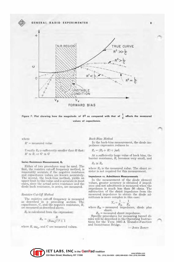
d('SiTI-d in Ih.· IIl·gllliv .... I"(·,i.;latlC(' r('lflu.l, this l'rror t('rlll nl\l~t ~, fllJPropriau'ly .. mnll. Thl're i5 no lII('anll of contro linJl: th .. !'rror I'Xct'I)t by fI hiM bhift llwny frolll the ~ogiOIl \\'h('re thc Ill'gatiV(' ret!lstfln.... i~ thl' ~ml\lIl'1't or hy II.
reduction in I.. In f,u:l, for !!oOlIlI' ,Jio..!l'lI it mllY be IlCl.-.$o:lrl' t .. '"H.'rat" nl'llll."T I h. , ]H.'uk lind vlIlI"l' r('~iolls t<l ohUlin ~\lnidpnt :\""UT!IPY, Ili:Ishown in Fil:llm i . In Ihi~ 1i"lm', r(·pl"<'wnt.ing Ihe low-fn'(JlIl'lwy "I~, thl' l'lTl'l"t uf 1(2
lI]lprollcbing ~ i~ ~h(lll' n. Tllc cxlr('lUl' ClIIJC
where R':5, t is not \I.~luLlly l'Iloount('I"t.'(lm pTa('
tkfLI diOOt'$, "inl't: this C(lITl-,;IMllI<ls 10 th, ' III'1,ilhilion rt.-gion O\'l'rIIlPlling the ~witchil\l;" rI'I'lon ul)I·ralioll.
For II diod" WIth (.' - ·IO"f, I. _ 2ml'h, /{ - 30 ohm~. If. _ I uhm, " !!lIiltlb]\! fr.~ lIlII'IUll' is h"t",,~·n 30l'.],· ltnd iO~k. lind 11ulII('ll";l\IrenWnt [II thc 1\,-g;.ltivl'-rc:;;b l'llIl'e n'ttioll "'111 nuL yil'ld grellt!'r lh:U1 II. 10(""(, ,·trot. Somt'-
IIIIIC:! thc condition J(~I"I > IO~ is not met... III
this 1:1L'tC, olX'rntiolL At ur Ilt'.v.t till' ("'CaK find \lllilcy point;o, wlll'l,\' Ibl' diode tIC n"'l~t'lIl('(' is Inrgl', U>oually yidd'! 1"I':t...'IOnlll)ly lwrurnte 1"CI<1I1l.'1.
[n addition 10 Ihtl ('rro!';! lI)cnliulLl'(l "h"''''l\ the mCfI.!Iurinlt; [1L~trUlZLt'lit ('an inll"<lIlu.·,·" further error ill Iht, nCI(!lti\,t~n."'i~t,Ulc(' n'J{ion. In must in.'5trumt'nt.~, "11"'1 thl' l"t.'Si.I,ul("" l"(tlllpolLcnt of til!' ltI'I"lIrL; und"r ,,·~t r-Imngl'll gl"l':.tly, a 1IIIlIIIIl'rror in Ihl' n~.('t 1\'(, ('f)lIlI)(IUI~lt will be ,JNduc,'tl . When the mculllIrl'd 1"I'~U'tive
(10
OOUIIXlur:nt is smfLIl, the pcrtenl'lg{! ('tror CIllI be Inrge.
Nevati .. , Ru i. "'"ce o. Co"ductonee M. OIu •• me ", I~or this mt'l .... urt'lncut thll 8:J.tlIe C<lIIrilti{HIS
and lIpproxiumtdy th{' Mme fl"t'ljllc'tt"Y-('hui('l' ,· •. m;ddl'r:llions nl),)ly Ill; for CII]l,u-itnu,'l' nlC"MIIrl"lncnL The rt.'ti~lIulo(' cxprebSiull (3) I"I:dll('f'8
'" R' - R-Il.
IET LABS, Inc in the GenRad tradition
534 Main Street, Westbury, NY 11590 www.ietlabs.com
TEL: (516) 334-5959 • (800) 899-8438 • FAX: (516) 334-5988
GENERAl RADIO EXPERIMENTEII •
+
u
--<
Vp VII
FORWARD BIAS
..... 1 ... ... f capocitanc •.
wll{'rt~
If' _ III(>Nmroo \'111\1{:
V~ulllly U, i.~ ~lIffil'i('lItiy smrLikr limn {{ tlULt: f~' 0lI H, "rG' ;:.; G
Set/ .. 1I .. lllanC. M . ....... m. nt. II,
Eithcr of two pl'OC('(!Urt"!I may be ll.'Jed. TIl<' lil'ilt, till' n"i&th'll "ulr<lfT fll,'qut'J\I'Y method, is TC9IIOIIflhly :.ccurntl' if the Jlt'gntive J'('Si!.l:\.IIOO Ilnd cllp1\('it:ul<'(l v,.luf'8 are known 1lccunildy. Th.., ~'()nd, Ihe blUlk-bias uWlhod, }'icld~ 11.11 upper limit to I hiH vnlll" Ilnd i;j !\cturatc in mo.st CIISl.'lI, sin('{" th!' 'wtll:lllleri,~ Tl'Olblllll('C wid the diode bllek l'L'ti i~lmu'( ', in seriei!, lire me:l$urOO.
fleri~lil'fJ CIJ.I.()JJ M clllQ<l
'I'h., m:oistive eut.-()IT fn:oqllCIlCY ill mCllI!llml all dl'!l('rilM-'(i in n prt'C(:ding lIl'Ction. T h. · I'Ilpad(IlIIl't', C, nnd the negative J'('Sist nnce, H, "n' melloun'd WI dCiJeribt.>d nbove.
R. i. CnlCullltro f rom the cll' pTC:8Sion:
R H. - (Rw.:;.C)'+ I
whf'1'f' n, Woo' nnd C nl"l' menSUrt'd \':IiUl'll,
Hock-Hifu M elht;Jd I n the b!lo:: k-uinll llLo::aI:Hlll'mf'nt, Ih(' diode im.
p('{i:l.IICC C"p~!!I.~h)U rtxluCo'''' to
A~ a sufi.idclltly Inrge vahl!' of Imck billi!, til{' baTtler rC:SI~ tflncc, R, 1.IC(.'t)lIIcs vcry ~m:\l I , wu.l
R. ~ R.
where ll~ is th(' melL'!ured value. T he shuut re~istor is no t /'("qllin'(l fo r thb! merullln::mCllt,
Impedanc. w •• Ad",i"an~. M. a l .... m.n's
In the IIIcru:;UTCDlcnt of the tHode element vn!ul'S, gTCatl:'r n(,(,lImey ill obtui u('(1 if impt'llalice IIlId not ndmi tt,tnc" ill meMu re<i when Ihe imp!'uancc ill mlLl'h ll'llll thll1l 50 ohms. T he suutmction of the shunt ltr1p •. ~ l an,.:e froll! til<' menljurlod imp,'{!:In"e to outuill III!' diode admittance ill more romplf'x in this Cu;jC:
I I Y' - 'J - '" "" ,-,
wh!'Nl Z .. - me,l.,'!.IIroo imp •. 'd"u(.'t', diode "lUll shunt.
Z" - trwllSul'f'U ShUIII impt'dnncc. SI)C(!ilic pl'()('('(jlln'l! for measuring tunnel di·
ooC'S will be dawribcd in the Op.crlll ing I II~tructiOllJl for the Tn.: WC17·A T rnnsf('r-Function and ImmitlallCC Briligc,
- Jon~ Z OllZY
-
IET LABS, Inc in the GenRad tradition
534 Main Street, Westbury, NY 11590 www.ietlabs.com
TEL: (516) 334-5959 • (800) 899-8438 • FAX: (516) 334-5988

9 JUlY.AUGUST , 1960
Tho lollowlng " .. 1<1., pu bili hed through 1"_ coope.a,l"n of th , Ray/h' .. n Compony, dilc"" " " ...... <lleal ''''''''pl . of 'unn" ...r;"d, m,olu •• ""nll, ", .. d e on Ihol compony' , CKM) . ,,1 .. dev , lopmental dlod ...
THE USE OF THE GENERAL RADIO IMMITT ANCE BRIDGE IN TUNNEL-DIODE MEASUREMENTS
by
E. Adler and R. C. Wonson-
The Geneml Radio Trnllsf('r~Func
lion tl.nd l lllmiUune(' Brid~c, T YI'E 1607-A, arrnngcd with the immittunce indicator in place. is highly suitable for making meai'turcments of tunnel-diode parameters. The plane where the flf:tual measurements are made I1m,v be c!L'<ily adjusted and determined, biuR can cru-ily be applied t.o the diode and spurious oscillations damped out, and no difficulty stands in the way of making mellsurements, either over a runge of bi:!!'; \'011-ages in order La obtain detai led information 011 the b('ha"ior of the diodt'S, or at n
very limited number of bias points so as to permit the rapid rdlltivc classification of a group of diodes. These rCll1:nks arc nmde on the bllsis of consider:lblc experiellce ~llitl\ .. "! in the t1!;C of t he b t'idgc, further details of whieh are sel out below.
The distussion t.hai follows is limited to the meusurement of the diode capucitance and negative conductance. The series inducl3ncc, hcing (:onsll\nt for a gin:-n p:wkage design , need be meru;urcd only 011(:,(', po"""ibly by lise of a dummy d iode. The g('ries resistance may most casil.\' 1m mNl,mr~[ Ill, conditions of vCl'y
Flg lI •• I . 810~k diagram 0' , ... m.olllring . qlllpm. nt . h.m l not Identifl.d by nom. a,.,
Typ. 8 74-Gl0 Find Att.nllato, no db) Typ. 87 4-W03 Op.n_C I '~lIh Te.mlnotlon Typ. 874_MR Miu, R.ctifle. Ty pe 1607-'2 Tee A ... mbl y TYIM 874-lK20 lin. 5, •• 1<"., Typ. 1607_'3 Aft Copo~ ltor
TYIM 874-l20 20-cm AI. Un. Typ. 1607· '5 Rang. ht.~ . ion Unit
T ... fa .. , ..... item. or. IlIppU. d 01 a part of f". brld" • .
TY PE t263-A POWER
SUP PLY
TYPE 121 6 - A
EJ TYPE 1215-8
I UNIT ose
UNIT I F AMP. to·50Me
(}) TYPE ~ 1208-8
MILUVAe UNIT ose H , T YPE TYPE TYPEde TYPE 01, TYPE JI I TYPE MV 17S fo"aOMe 8N·GIO 874-MR I 607,P2 874 -LK20 874 - L20 B74-W03
I TYPE ~eONNEeT UNKNOWN HER E 1607-P3n / TY PE 1607 - P5 'W f TYPE .74~
3>' i' loon !'- W YPE 1607-P2(2)
TYPE 160 7-A IMMITANCE BRI DGE
I IMMITTANCE INDICATOR
IET LABS, Inc in the GenRad tradition
534 Main Street, Westbury, NY 11590 www.ietlabs.com
TEL: (516) 334-5959 • (800) 899-8438 • FAX: (516) 334-5988

" 0
'w
,~
w • ,
0 • l • -w
GENERAL RADIO EXPU; IMENTER " ' IIIIV" 2, Coo. lal ,.,oVIII v,_ ,. ~oll".cI ,h. d lod. 10 Ih. brldg., s..
01.0 ~o" .. pho'o,
DIODE
RESI STOR 110£1)
SHEll ";"R;~~A; ; o.;'. I!IQ-OHM
Jar~c nppliccl reverse bins, in which cusc methods employing tedllliqllcs other than those associated with the bridge p,'<'&'ntly cOllsiderro nrc prcfernlM, CXCtpl. where a high-frCtjuelicy mcnSUl'cnl('l!t is -spedficnlly desired,
'I'll(' condi tions of m('mml'em('llt were similar 10 lh()"e outiilll .. '<.i in the prl'ecding articlc ; I\. shunt resistor WUi\ 11$("(1, 10
R.-;SUH' Ihnt t he unknown dement pre-8('llt("(t a positive l.:onductIlIWl' 10 the bridl(l': 111(' mOllnl was ti(>:<iltn("(j 10 locate the me:lllun'llwnl pOint ill the phllc of the d iodf' jUlltlioll; und t hc !'< ip:u:tllcvel wu;; kept low, OlH.' millivolt or If' ..
A block difUtram of til{' hridgp alld ulwillary {'(luiplIH'nl uSl..~ 1 for the IMIS d~I'ih('(1 is !'<ilo\\/1 ill fi,l!;ur{' I. It was found n('Ce~lIry to conSl tlld :\ ('ollXinl moun t· to hold Ihe diode,. nud the stnbi lizill,ll; n~i"'tor, so t hat Ihe wholl' {'ould 1)(> easily Illtl~oo into t he IIppropriltlt.' -Alter. tieoi4n II), ~, Cohen of Ra)'theon Co, lU ...... ,..,1I I);v, j,
bridge terminal. A modified Gellcmi Radio Tn'E 874- W;\ 1 5O-ohm Termina.tion was found 1.0 hI' cII,.;;ly !ldaptcd for Ihi!> purpose (see Figurc 1 ), T he final uni t. tonsists of the 874·W'\'1 shelll Il. 10-ohm disk res;;;tor, and fittinp:s to hold the diode ill place, A disk rc!'< islm is used, not only for COII\'{'nierICC hul. 11l!;0, and morc importtUltly, to kl'Cl) til(' !;Nics induelancp irl the diodc-plus-p!lmllcl·rcsistor circuit low and t im ,.; \'err effectivcly to IIntisfy the diooe Slaililit ,\' t'riter'ion; in addition, thi;; IH'I'lInp:ement keeps the eirt'uit to be lI1ell."urcd :I.E; nend y as pog... sible in one plane,
The sut't'L'i'..;oive steps ill the measureIIll'lIt procedure nr(' tiS follows:
1) The ;nitiul ;;('lIi1l,ll; up of the bridge consists of s{'t t itl,ll; til(' output line to one half wtl\'p!elll!:lh tUlt.! "ll'flppitl,ll; out" the 1(:H:a! os<:illat or 8i,l!;l1a\ :1'1 pl'('SCr'il}('(1 in the ill.<;tructiOIl mnlll1:11 in on\!'r 10 prevent parnsilic si~lmls from retlching the diode,
t._ ~o .. c I' ~ • •
1\ SUSCEPTANCE ,
~o ,w ~ ,w ao
I BIAS
-
-V
I ,~ -
/ A
I
.~+
f ill v.. 3. Ad"'ilt<> .... ~h •• acl .. I"'lu of Ra .,_ .lIeo ll CK<IO .,rI •• di· ""'"' od .. a . 0 " ... d ion of b lal, "' ... ... 0<1 al 50
Mo .
IET LABS, Inc in the GenRad tradition
534 Main Street, Westbury, NY 11590 www.ietlabs.com
TEL: (516) 334-5959 • (800) 899-8438 • FAX: (516) 334-5988

-
" The con-cd setting of the output. line may be I>crformed with :\11 874-\V~3 Short Circuit. in place of ,be diode holder if desired, Fillce this provides subslnnl ially the sumc reference plane as the ltlttcr.
.\1tcrllativeiy a special (shol'l. circui ted ) diodl' may be placed in The hold!"!'; tbiti chuice if! IJcttCI' itl principle, since any leud illduclallcc clTects should be :U1tomalically compcns.'l.tt.."(1.
2) The admittrulCC of the diode mount must. be measured wiih the resistor , but no diode, in place. This value elm Ihell be ,;uolnu:t«1 from the readings tnken with !he diode in plnce, to oblail1 the true diode milK'!).
3) A billS ca llumtioll is required. The components ill the dCf'Qupling ein-uits wbidl isol:1te the coaxial bl'id~t' li nes from the external bias supply include series chokes h:\vin~ rclatinoly large rL'
~isbllccs. The complexity of the relation hetwccn the voltage applietl to the bilts terminal!l on the bridge nnd the actuul bins tl.1}pliCt\ at til!' diode will depend on the division of current betwccn t he diode nnd the stabilizing resist or, nnd thth! it is simplest to t:ll;:c a dirl.'Ct calibration, cOIlIll.'Cting a cott-xial tee bclw~'cn the diode mount alld the bridge socket for
, if
"'r- --J g , , ,
, " "
00
-,
fill" ' . 4. Admillonu - :3 d.o. " ..... illl .. 01 m_'"
..... d 01 sao M~. -.
'" 00
00
t::-\
'--
~ • n ~ • " • z n ~
'" I
JULY . AUGUST , 1960 ~
this purposc. The tee ~hou ld IX' f('moved when the diode nclmitta.ncc mc:umrcmCllls arc made.
4) The !wtual diode admittance measurement is Ill:\de. the results bei ng adjusted in IlCCOnlnllce with (2) above.
FigUl'C 3 shows t.ypical rcsu lts obtnint.'(.1 from measu rellleuts, m~illg the nbove techl1 iqu~, 1ll!lde 011 a number of Unythcoll C I\,IO series developmental tunnel diodcs. Tht:'Se curvcs possess the shapes to be cxpectOO 011 lhe basis of thoorctical predictions flUd agree elosely with results obtained by alternative methods. It. is intended to include n. more detailed discussion of this subject ill another Mti('l~. hut it might be mentioned that the ch:ll1p::c of diode suscept.ance from ctlj)acitivc to inductive vI'\.1ucs at the extremes of the bins runge is erroncous, being caused by the inductance ami the decrellsc in diode rcsist:l.nce so
that R'l is l\ot large comp:u-txl With~. The
effect of series inductance can be carried to the limit. i.e., to the extent. where resonance with Ihe diode capttcitancc takes place, by m('mlttt·pnl<.'I1~ HI a higher frequency. Figure I ~how!'o curvl.'S obtained at a frC'qI1('lIcy of :ilO Me.
I fo.I!lOOMC
r--
I ,., , .. '" '" '''' '" ~ ~20 .. Y , BIAS --
-- ---....-v: /
L.. ___ _ j
IET LABS, Inc in the GenRad tradition
534 Main Street, Westbury, NY 11590 www.ietlabs.com
TEL: (516) 334-5959 • (800) 899-8438 • FAX: (516) 334-5988

~ GE N ERAL .ADIO EXPERI M ENTER 12
It should be pointN\ out tlUlt, under lector hllving suflicicllt iy high sensi-somo circumstll.II('('!,I, there Zlrc advantages in IllCll.."uremcnt III lower fn.'quell('ies, B.ud it is l:l4'J&;iblc to operate the bridge at frcquenti('s below the mnnufacturer's pre;cribcd limit. pro\'ided care is taken in colllle<'tiou wit.h such dimcuhics n.~ these:
a) sdf-rcsonnncc of the bi:UH:ircuit. filters cnn occur, so that measurements must be confined to f f<'<llIcncics on either side of this resollallce.
b) the lill'C{! coupling circuits from the gCIlt'rator to the bridge eienH'llta beeorne progrl'S-",ivcly l~" efficicllt as fr~ qUC'llcics IIrc lowen'd, but this problem can 1)(' ovcn:ome by the use of a de-
ti,·ity. c) the hnlf-wtwclcllgth line connected
in the "unknown" arm of the bridge can become very long and iL may be necessary to usc hi~h-grade nir line to keep losses to f\ minimum.
The modified mi("rowtl.vc-<Iiodc-pnckage form of the Haythoon tun net diode, giving the ndvtlntng(' of nry low S('ries inductance, is well suitoo for conn('(:tion to the inun iu:lIlce Bridg('. Diodes encIlpsuiatNi in difTer£'nt packages, e.g. slIlndnrd J I~TEC cases or dcsiA:lls intended for Strilriine apl>licIltions, (,Iln nl!1O be m(,Murcd provid{'(1 suitable jigs and fixtur('8 arc designed.
WESCON 1960 GENERAL RADIO COMPAN Y
BOOTHS 95 7 - 958
~1(·:l:.-ur(,lllcnt:i on ~mi('onductors will be a f('atllT(' of th(' (;('n('rnl Hadio exhibit at W l'S('OIl lOGO. Opl'ruting exhibits will demonsl mt(' the nU'n~lll'('mClll of lunncldiode pamm('tcrs with the Tn'.; In07-A Tmn .. o:fl'r-Funrlion nlld I mmitlall('e BridA:l' and the r:t.pid rnCal;ur('mcnl of smtlll (';lpaeiltlll('{'8 in trnnsi!ltors tlnd
diod<'S with the THE IG05-A ImpOOIlncc Compumlor.
Other inr-;truments ill opcrIltillg displIlYs inducle:
Tn!::: 1300-:\ lknt-Frcquclley \ 'ideo Gellernlor
TnE 1300-13 Hal1dom-~oi.sc Generator
TYl'.~ 1551-A Sound and Vibration Analyzer
Tn.; l.j21-.. \ Gmphic I...c\'('1 Hecorder
'1'"".: 1:17O-A Automatic \'oltagc Regulator
Tn'.; 16r)()... .. \ Imp('(lnncc Brldc;c
,"uri:\('- Autotransformrrs with /Jura/,ok contact surface will also be displayed.
General Radio Company
... ;:, ...
IET LABS, Inc in the GenRad tradition
534 Main Street, Westbury, NY 11590 www.ietlabs.com
TEL: (516) 334-5959 • (800) 899-8438 • FAX: (516) 334-5988