the generalized requirement approach for … generalized requirement approach for ... (sdm) and...
TRANSCRIPT

Interdisciplinary Journal of Information, Knowledge, and Management Volume 9, 2014
Cite as: Bulajic, A, Stojic. R., & Sambasivam, S. (2014). The generalized requirement approach for requirement valida-tion with automatically generated program code. Interdisciplinary Journal of Information, Knowledge, and Manage-ment, 9, 59-88. Retrieved from http://www.ijikm.org/Volume9/IJIKMv9p059-088Bulajic0500.pdf
Editor: Eli Cohen
The Generalized Requirement Approach for Requirement Validation with Automatically
Generated Program Code
Aleksandar Bulajic and Radoslav Stojic Metropolitan University, Belgrade, Serbia
[email protected], [email protected] [email protected]
Samuel Sambasivam Azusa Pacific University, Azusa, CA, USA
Abstract Requirements gathering is one of the first steps in the software development process. Gathering business requirements, especially when the final product requirements are dictated by a known client, can be a difficult process. Although clients know their own business best, often an idea about a new business product is obscure and described using general terms that contribute greatly to common misunderstandings. Business requirement verification in the event that requirements are gathered using text and graphics can be a slow, error-prone, and expensive process. Misun-derstandings and omitted requirements contribute to the need for revisions and increase project costs and delays.
This article proposed a new approach to the business software development process that is fo-cused on the validation of business requirements during the requirement negotiation process. The process of the business requirement negotiation is guided by a set of predefined questions. These questions are guidelines for specifying a sufficient level of requirement details in order to gener-ate sources and executable code for requirement validation without manual programming. Be-sides requirement documenting, tracking, and validating, this method addresses requirement management syndromes and the specification of an insufficient level of details.
Keywords: Business Requirements, Software Requirements, Requirement Negotiation, Software Development, Generalized Requirement Approach, Software Development Method, Requirement Management.
Introduction Gathering business requirements can be a difficult process, especially when the final product requirements are dictated by a known client. Business requirement validation in cases where the require-ments are gathered using text and graph-ics can be slow, error prone, and expen-
Material published as part of this publication, either on-line or in print, is copyrighted by the Informing Science Institute. Permission to make a digital or paper copy of part or all of these works for personal or classroom use is granted without fee provided that the copies are not made or distributed for profit or commercial advantage, AND that copies 1) bear this notice in full and 2) give the full citation on the first page. It is permissible to abstract these works so long as credit is given. To copy in all other cases or to republish or to post on a server or to redistribute to lists requires specific permission and pay-ment of a fee. Contact [email protected] to request redistribution permission.

Requirement Validation with Automatically Generated Program Code
sive. Misunderstandings and omitted requirements force additional revisions and increase a pro-ject’s costs and delays.
When issues related to the requirements are discovered later in the project, there are even greater costs and delays. Discovering or modifying requirements in the Design Phase can be three to six times more expensive, in the Coding Phase up to ten times more expensive, and in the Develop-ment Testing Phase between fifteen and forty times more expensive. In the Acceptance Phase, modifications can be thirty to seventy times more expensive, and in the Operation Phase it could be as high as forty to a thousand times more expensive (Dragon Point Inc., 2008).
Architecture and design depends significantly on the Requirement Specifications. Misunderstand-ings or misinterpretations of the requirement can lead to wrong architectural and design decisions, as well as the propagation of failure into coding and latter project phases. One of the worst-case scenarios is when wrongly implemented requirements are discovered after deployment on the production platform.
A research study reported that more than a quarter of completed projects contain only 25% to 49% of the originally specified features and functions (The Standish Group, 1995).
The IBM Project Management presentation used the Meta Group study to illustrate that 70% of large IT projects failed or did not meet customer expectations (IBM, 2007).
This paper proposes a new approach to the software development process to the improve re-quirements negotiation process and enable requirement validation during the requirement negotia-tion process. In the Generalized Requirement Approach (GRA), requirement validation is accom-plished using automatically generated source and executable code without manual programming. The source code and executables are generated by the Generic Programming Units (GPU), the basis of the GRA Framework. The GRA Framework, which is the implementation of the GRA, provides guidelines for documenting and specifying requirements, methods, and libraries that are used to generate source code and executables. The questions that are part of the GRA Framework are guidelines for specifying a sufficient level of requirement detail to generate sources and ex-ecutable code for requirement demonstration. Besides requirement documenting, tracking, and validating, this method addresses common requirement management syndromes, including a specification of an insufficient level of detail (Bulajic, Stojic, & Sambasivam, 2013a), the IKI-WISI (“I’ll know it when I see it”) Syndrome, the Yes, But Syndrome (“That is not exactly what I mean”), and the Undiscovered Ruins Syndrome (“Now that I see it, I have another re-quirement to add”).
This paper is organized in the following sections:
1. Introduction – this section 2. Background 3. Literature Survey 4. Traditional Software Development Method 5. Generalized Requirement Approach 6. Generalized Requirement Approach Framework 7. Retail Store Example Application 8. Summary of GRA Features and Comparison to other Approaches 9. Conclusion 10. References
The section “Background” discusses the Software Development Methodology (SDM) and com-pares sequential and iterative software development processes.
60

Bulajic, Stojic, & Sambasivam
The section “Literature Survey” presents software development methods that have contributed to the software development process. This presentation is limited to the major methods that are cur-rently used for software development.
The section “Traditional Software Development Method (SDM)” is an overview of the current software development process structure that is common for the software development methods presented in the Section 3 “Literature Survey”.
The section “Generalized Requirement Approach” describes the proposed method for improving software development process based on requirement validation during the requirement negotia-tion process.
The section “Generalized Requirement Approach Framework” describes the GRA Framework and the implementation of the GRA method. The GRA Framework is responsible for guiding user to specify requirements, store requirement descriptions in the structured text format, and generate source code and executables that are used for requirement validation.
The section “Retail Store Example Application” describes the GRA implementation with the the Retail Store, a fictive E-commerce application, which is used to validate the GRA Framework implementation.
The section “Summary of GRA Features and Comparison to other Approaches” is a summary of the GRA features and describes the differences between the solution proposed in this paper and current software development methods.
The section “Conclusion” draws a final conclusion and describes the limitations of the proposed approach.
The section “References” contains a list of the literature used for writing this paper.
Background The Software Development Method (SDM) is a process of software development that can be described by the following development phases and activities:
Analysis – system requirements management Architecture & Design – system design Development – internal design and coding Test – test and validation Deployment – operation and maintenance
The SDM is a structured approach to software development. The SDM’s purpose is the produc-tion of high-quality software in a cost-effective way (Sommerville, 2001). The reason for the structuring process is to enable process planning and controlling. The SDM process structure is implemented in multiple software methodologies—sequential and iterative, incremental and evo-lutionary, rapid application development, and prototyping.
The sequential approach to the SDM is identified by the waterfall (Benington, 1956; Royce, 1970) software development method, and the modern, iterative and incremental software devel-opment method, which is today collectively known as the agile development method (Beck et al., 2001a).
A traditional requirement management approach is often identified by the Waterfall software development method, where comprehensive requirement analysis and documenting is completed before the start of the next project phases.
61

Requirement Validation with Automatically Generated Program Code
On the contrary, the agile requirement management system does not wait until all requirements are specified or wait for a whole requirement to be specified. Development starts as soon as a part of the requirement is considered to be understood. The project is developed by using an iterative approach (Beck et al., 2001b).
An iterative approach breaks a project into more pieces or phases, where each phase’s output is functional software that implements a limited set of requirements. The last phase is supposed to deliver fully functional software that implements all requirements and is ready to be deployed in the production environment. Each phase adds a new value to the existing software and incremen-tally builds the entire product. The requirements are refined during the planning of next phase and corrected by a better understanding collected during the development phase with feedback re-ceived from the client (Cockburn, 2008).
The Waterfall method is most appropriate for a project where requirements are stable and do not change very often, or at least change only during development and implementation phases. How-ever, analysis shows that an average of 25% of requirements change in a typical project, and the change rate can increase even higher to 35% to 50% for larger projects (Larman, 2005).
Other statistics from the same source (Larman, 2005, p. 23) show an “average of 45% of the fea-tures in waterfall requirements are never used, and early waterfall schedules and estimates vary up to 400% from the final actuals.” While some interpret this statistic data as a method’s failure, the authors would rather interpret this as a human failure.
The agile method approach also utilizes the Waterfall method, or better to say divides an entire project into short waterfall phases. This difference is significant when requirements are not well known or changed frequently. Another important difference is that the agile method provides frequent deliveries that in turn cause frequent test execution and feedback from clients and test-ers; therefore, mistakes and failures are discovered earlier.
Literature Survey The history of software development is a history of continuous searches for better methodology and tools that can improve the software development process. In this section are presented the software approaches that contributed to the improvement of the software development methodol-ogy. The presentation in this section is limited to the major methods and tools that are currently used for software development.
The software development process is complex and there does not exist a single methodology or tool that can solve all possible issues. Each methodology or tool solves a particular set of issues and can be successfully used to solve a class of related problems.
The Unified Software Development Process (UP) is an iterative and incremental component-based software development method that is case-driven, architecture-centric, and risk-focused. The UP was created by Ivar Jacobsen, Grady Booch, and James Rumbaugh (Leffingwell & Widrig, 2000). The UP software development method defines four development phases called Inception, Elaboration, Construction, and Transition. Each of these four phases can have one or more iterations that execute Business Modeling, Requirements, Analysis & Design, Implementa-tion, Test, and Deployment activities. This method uses a Unified Modeling Language (UML) for object-oriented modeling.
Leffingwell and Widrig (2000) describe the road map used in the Unified Process method as:
1. The Problem Domain 2. Stakeholder Needs 3. Moving toward the Solution Domain
62

Bulajic, Stojic, & Sambasivam
4. Features of the System 5. Software Requirements
A Problem Domain is identified by Needs, while Features and Software Requirements belong to the Solution Domain (Leffingwell & Widrig 2000).
The Microsoft Solutions Framework (MSF) is the implementation of Microsoft’s best practice method for delivering software according to specifications, time, and budget (Microsoft, 2003).
Besides the MSF disciplines Project Management, Risk Management, and Readiness Manage-ment, the MSF key concept is based on the proven practice and foundational principles that foster open communications, shared vision, learning from experiences, agility, and focus on delivering business values, and team models.
The MSF Process Model is based on phases and milestones and is a combination of the waterfall and spiral software development methods. (Microsoft, 2003).
Besides creating Extreme Programming (Beck, 2002a) and being a part of the development of the agile software development methodology, Ken Beck re-invented the test-first approach or Test Driven Development (TDD) (Beck, 2002b). Some translate the TDD acronym to mean Test-Driven Design. The TDD approach requires writing the test code before writing the implementa-tion code, and the implementation code is refactored to remove duplicates when more than one test code is written. This approach improves test coverage and the overall testing culture.
A number of studies and experiments have been accomplished at universities and large software companies, such as IBM and Microsoft, where the primary goal has been to answer the question of how effective is the TDD software development method.
Bulajic, Sambasivam, and Stojic (2012) analyzed the results of multiple published research pro-jects and experiments where the primary purpose was to confirm the TDD’s claimed benefits and advantages. The paper analyzed on reliability of the results and reliability of the empirical pro-ject’s design and participants.
It is difficult to draw a final conclusion regarding claims that TDD improves internal software design, makes further changes and maintenance easier, and uses the same or less amount of time for project development, because the results of the empirical studies differed significantly (Bula-jic et al., 2012).
In 1993, Jeff Sutherland created SCRUM, an agile software development method. Most of the software development tools offered by major software companies claim that they support the SCRUM software development method. SCRUM is best known through its SPRINT planning, SCRUM backlog, monitoring team member and team performances by burn-down graphs, daily SCRUM stand-up meetings, and the SCRUM retrospective. As with other agile software devel-opment methods, this method best fits to small development teams (Sutherland & Schwaber, 2011).
Despite the existence of so many software development methods, according to Standish Chaos Report 2009, the software development success rate is getting worse. While in 2006 the Standish Group reported 35% of projects were successful, 46% were challenged, and 19% failed, in 2009 they reported 32% were successful, 44% challenged, and 24% failed (Eveelens & Verhoef, 2010).
The software development methods analyzed in this “Literature Survey” section assume that the first step in the software development process is dedicated to Requirement Engineering. The Requirement Engineering is described as a process of requirement analysis, elicitation, specifica-tion, and verification (Wiegers, 2003).
63

Requirement Validation with Automatically Generated Program Code
The goal of the requirement verification process is the confirmation that the requirement is de-tailed according to a good requirement specification. A good requirement specification means that the requirement description is consistent, complete, correct, verifiable, and traceable. The requirement verification requires that requirement specification is already written. Sommerville (2001) describes the requirement verification as an iterative process between requirement specifi-cation and requirement verification.
The requirement verification is in most cases accomplished by a formal inspection of the re-quirement specification document internally using small teams. The inspection can be supported by developing functional test cases and specifying acceptance criteria (Wiegers, 2003).
In the Rational Unified Process (RUP), which is an implementation of the Unified Process (UP), a traceability matrix is used for verification. In this matrix, requirements are linked to features, features are linked to Use Cases, and Use Cases are linked to Test Cases. If any of these links are missing, the requirement is not considered properly verified.
Linking requirements described by the User Story to Use Cases and Use Cases to Test Cases is a common verification technique that is employed in iterative and incremental development meth-ods such as the agile methods. The verification is based on peer-review techniques and inspection of the requirement documentation. The agile approaches most often use the User Story as a re-quirement description and from the User Story develop a number of Use Cases and Test Cases. The inspection process should confirm that the User Story requirements are covered by Use Cases and Test Cases.
The inspection technique, a traceability matrix, and model drawings are manual verification tech-niques. However, business requirement verification in cases when requirements are gathered us-ing text and graphics can be slow, error-prone, and expensive.
Sommerville (2001) sees prototyping as a requirement verification technique.
Prototyping is a well-known practice in the software industry and some of the major prototyping purposes include requirements clarification, design alternatives exploration, and growth into an ultimate product (Wiegers, 2003).
Sommerville (2001) describes the following prototype categories:
1. Throwaway prototyping 2. Evolutionary prototyping
Sommerville compares prototyping to the evolutionary software development method; a “proto-type is therefore part of the requirements engineering process. However, the distinction between prototyping as a separate activity and mainstream software development has blurred over the past few years. Many systems are now developed using an evolutionary approach where an initial version is created quickly and modified to produce a final system” (Sommerville, 2001, p. 172).
Although the Generalized Requirement Approach introduced here can be considered a form of prototype, there are significant differences that are presented later in this paper.
The automatic code generation is supported by specially designed computer languages that are able to generate application software. Such languages can be divided into (Tse & Pong, 1991):
Textual language – based on natural language or “formal programming languages” Graphical language – that consist of the limited number of understandable symbols Hybrid language – combination of previous two, graphical language for presenting an
overview and textual language for detailed description
64

Bulajic, Stojic, & Sambasivam
The textual languages based on the Natural Language Processing (NLP) belong to the field of Artificial Intelligence (AI), and search for algorithms “that allow computers to process and under-stand human languages” (The Stanford Natural Language Processing Group, n.d.) .
The natural language is subject to different interpretations and can cause ambiguities. “Standard English prose is not suitable even for specifications which are processed manually. Languages that have a better defined syntax and slightly more restrictive semantics would therefore be pre-ferred. These languages are more formal in nature and resemble a programming language or a mathematical language” (Tse & Pong 1991, p. 3).
One example of a formal specification language is the Requirement Specification Language (RSL). “The purpose of RSL is to describe precisely the external structure of a system comprised of hardware, software, and human processing elements. To overcome the deficiencies of informal specification languages, RSL includes facilities for mathematical specification” (Frincke, Wolber, Fisher, &Cohen, 1992, p. i).
Another example of the formal specification language is the Specification and Description Lan-guage (SDL). SDL is used for real-time telecommunication applications and for the development and simulation of complex event-driven communications systems (IBM, n.d.).
The formal specification languages are based on mathematical analysis and algorithms. While mathematical techniques are widely accepted and used in other engineering industries, such as mechanics, civil engineering, and electrical engineering, mathematical techniques are not widely used in industrial software development (Sommerville, 2001).
Sommerville (2001) emphasized that software development is based on the three levels of speci-fications. The user requirements specification is the most abstract, the system requirements speci-fication is in the middle, and the software design specification is the most detailed specification. Formal specification languages generally support the processes that are “somewhere between system requirements specification and software design specification”.
Traditional Software Development Method The traditional Software Development Method is described in Figure 1.
Figure 1. Traditional Software Development Process
65

Requirement Validation with Automatically Generated Program Code
An idea about a new business product is often obscure, described in general terms that contribute to common misunderstandings. The requirements are collected during the Analysis phase and described by text and graphics. Requirement verification in this case can be a slow, error-prone, and expensive process. Misunderstandings and omitted requirements force additional revisions and increase the project’s costs and delays.
Even though it is well known that written text and graphics are ambiguous and subject to different interpretations, the Requirement Specification is used as the reference document during the soft-ware development process. The Requirement Specification is not a guarantee that a requirement is properly understood. At this point in the process misunderstandings are not yet visible
The Architecture & Design phase often uses specific technical terms and graphics. The architec-tural drawings and descriptions can be obscure even for those people who work in the same com-pany; therefore, the descriptions may require additional explanations from the author.
In the Development phase, the requirements are described by code and syntax that is specific for a particular programming language. The code is then translated to an even more obscure binary code and executables.
The executables created in the Development phase are used during the Testing & Validation process to validate the Requirement Specification. It is here that a customer can see if the imple-mentation satisfies his needs that were expressed at the beginning of this process using text and graphics.
This process can be improved by introducing a requirement demonstration as early as possible in order to avoid wasting time and resources on the implementation and subsequent modification of misunderstood requirements.
Generalized Requirement Approach The Generalized Requirement Approach (GRA) possesses the following features:
1. Requirements are described using the customer’s native language and stored in the struc-tured text format document
2. Generated source code is based on requirement specification without manual program-ming
3. Demonstrated working software during requirement negotiations process
Figure 2 illustrates the GRA method:
The GRA assumes that customer requirements described in a native language may be converted to a structured text format. This is true in most cases for a functional business requirement.
Before the customer requirement’s translation to the Requirement Specification, the customer requirement must go through a Requirement Normalization process. The Requirement Normali-zation process is responsible for:
Describing a requirement with a sufficient level of detail by using the customer’s na-tive language and storing in the structured text file,
Demonstration of the requirement by generating source and executable code, based on normalized requirements, without manual programming during the requirement negotiation process.
66

Bulajic, Stojic, & Sambasivam
Figure 2. Generalized Requirement Approach (GRA) Overview
The Requirement Normalization process is considered complete when a requirement is describ-able with a sufficient level of detail from which it is possible to generate source code and build executables. There is no limitation as to how much or how little the customer requirements will be described during Requirement Normalization phase before continuing to the next Coding phase. This is an iterative process and the Requirement Specification can be created incremen-tally.
Requirement Normalization is the GRA method’s driving force during the requirement negotia-tion process. The output from this process includes:
Requirement Specification Source Code Test Cases, if test cases are created during the requirement documentation process
The Requirement Specification is used during the Coding phase and needs to be updated by im-plementation specifics solutions, comments, and issues. It is assumed that the architecture and design activities are accomplished during the Coding phase. A direct update of the Requirement Specification is not recommended using the GRA because the Requirement Specification is gen-erated by the GRA. The Requirement Specification can be updated through Customer Require-ments and the Requirement Normalization processes. The source code generated in the Require-ment Normalization phase can be used in Coding phase for further development. The Design Specification is created from the source code.
The output from the Coding phase is the source code and executables, and these are validated in the Code Testing and Validating phases.
The Requirement Normalization needs to be carried out by the GRA method using a system. The GRA Framework (GRAF) is the GRA method’s implementation tool, and besides documentation purposes, the GRA Framework contains classes and libraries that are used for automatic code generation, which is one of the preconditions for the Test & Validation phases.
67

Requirement Validation with Automatically Generated Program Code
Generalized Requirement Approach Framework Figure 3 illustrates the high-level design of the GRA Framework (GRAF):
Figure 3. The GRA Framework Design Overview
The Designer is responsible for storing structured text format descriptions in the Database and is responsible for guiding the user to specify a sufficient amount of details. The Code Generator is responsible for generating source code by using the structured text data stored in the Database. The source code is generated in the standard programming language, for example, C# or Java. The generated source code is executed in the Runtime Environment. The requirements are vali-dated in the Test & Validation process. If a requirement does not satisfy expectations, the process can be repeated and returned back to the Designer.
While the method’s features are generally valid and used as guidelines and recommendations, the application of the method features can be implementation-specific. Each implementation can be based on the different object types. The GRA Framework used in this paper identifies the follow groups of objects that are used by the Designer during the requirement negotiation process:
Objects responsible for requirement documentation, such as a User Story, Requirement, Use Case, Test Case, Project, Component, Transaction, and Defect objects. The informa-tion stored in the attributes of each of these objects are not used for the generation of source code
Objects responsible for storing data in a structured text format that are used to generate source code, such as Forms, Data Sources, Application Objects, and Interfaces
68

Bulajic, Stojic, & Sambasivam
Each of the GRA Framework’s objects is mapped to one or more corresponding database entities that are used for storing data in the structured text format and for retrieving data when the GRA Framework needs it.
Objects responsible for requirement documentation, such as User Stories, Use Cases, and Test Cases, make up the implementation of the requirement management’s best practice.
Object responsible for storing data in a structured text format are business application building blocks. The following list describes each of these objects and the context in which the objects are used:
Forms – describes entry fields and other predefined Graphical User Interface (GUI) con-trols, and enables the user to enter data, assign actions to data, and process data with a mouse click
Data Sources –responsible for creating database tables and relations Application Objects –responsible for backend or batch job processing Interfaces – are at the same time Application Objects, but for this kind of object is a spe-
cific communication with sources of data external to the application.
Details about the Code Generator are described in Figure 4, in the “Generate Source Code with-out Manual Programming” section.
Document and Storage Requirements in the Structured Text Format described by the Customer’s Native Language Storing a requirement description in the structured text format is a precondition for automatic source code generation. The requirement description is guided by a set of predefined objects and their attributes. Each object stores data about a closely related class of objects. For example, the User Story can be generally described by the common template, “As <role> I need/want <goal> to achieve <benefit>”, or by using a controlling documenting template such as the Five Ws tem-plate (Who, When, Where, What, Why). The User Story is described using the customer’s native language.
Documenting requirements in the structured text format as described by a customer’s native lan-guage is illustrated using the Form example. The Form is utilized for customer interactive com-munication with application software. In the Form, the customer can enter the desired data and, by clicking on an action button, send data to processing inside the application software and re-ceive results.
The Form structure can be described using:
form name field name data type length number of decimal places control type action type
The Form’s structured description can be used to describe different arrangements and each form can have different fields. For example, PRODUCT and PAYMENT forms can each have differ-ent fields and a various number of fields. The Form name as well as the name of each form’s fields can be described with the customer’s native language. For example, the form name can be PRODUCT and the fields name can be PRODUCT_NAME, PRODUCT_DESCRIPTION, PRICE, and QUANTITY. Another form name can be PAYMENT and the field names can be
69

Requirement Validation with Automatically Generated Program Code
CREDIT_CARD_TYPE, CREDIT_CARD_NU, EXPIRATION_DATE, and CON-TROL_CODE. The customer then understands the business meaning and context where these names are/can be used.
Generate Source Code without Manual Programming The GRA method assumes that the source code is generated without manual programming. Fig-ure 4 illustrates how this feature is implemented:
Figure4. Generalized Requirement Approach Framework Source Code Generation
The source code is generated from the structured text descriptions using the GRAF Libraries, and the structured descriptions are stored in the Database tables. The GRAF Libraries contain param-eterized methods and templates. These methods and templates are adapted to requirement specif-ics and inserted in the generated source code. The methods and templates are used as building blocks to create source code. The process of source code generation is initiated externally from an Actor by sending the name of the object that needs to be generated.
The Generic Programming Unit (GPU) is a computer code that creates source code using struc-tured text descriptions stored in the Database, library methods, and templates. The GPU reads the data stored in the Database for each particular object and creates source code according to re-quirement descriptions by using the GRAF Libraries and Templates. While Templates are stored in the GRA Framework’s internal memory, the GRAF Libraries are stored in the files. The GRAF Libraries, besides containing the methods, can also contain templates. The outputs from the GPU are a HTML Web Page, Code Behind Class, Data Object Class, and SQL. The Data Object Class is responsible for data mapping from a relational database to the objects. The generated SQL statements are used in the implementation of create, read, update, and delete (CRUD) database operations. The GPU should be able to generate other source code when necessary if there are sufficient details of information available and if the implementation technology can support it.
70

Bulajic, Stojic, & Sambasivam
The Runtime Environment is responsible for execution of the generated source code and uses the Database for storing and retrieving application data.
The process of generating source code will be illustrated on generating source code for the PRODUCT form. The example is generated according to the Microsoft ASP.NET specific im-plementation requirements, and this example uses Microsoft ASP.NET specific templates and libraries. If it is necessary to generate HTML or Java Server Pages, then different templates and libraries specific for these implementation technologies will be used.
In Table 1 is a description of the PRODUCT based on the form structure described in the previ-ous section.
Table 1. Product Form Fields Description
form name
field name data type
length Dec. Places
control type
action type
product productid string 50 0 TextBox N
product name string 50 0 TexBbox N
product description string 100 0 TexBbox N
product price numeric 7 2 TexBbox N
product quantity numeric 5 0 TexBbox N
product selectedquantity numeric 5 0 TexBbox N
product btnAddToSC string 20 0 Button addRowTo(ShoppingCart)
product btnShoppingCart string 20 0 Button redirectTo(ShoppingCart)
The FORM description is stored in the Database table. The Actor requires generation of the PRODUCT form. The GPU reads all product fields and generates code.
The HTML Web Page (Microsoft ASP.NET aspx file) is created from the templates that represent the beginning of the HTML file and ASP.NET controls, such as a TextBox control and Button controls. The beginning of the aspx file, in this case the product.aspx file, is built from the follow-ing template:
<%@ Page Title=\"\" Language=\"C#\" MasterPageFile=\"~/Site1.master\" Auto‐EventWireup=\"true\" CodeFile=\"@pageName.aspx.cs\" Inherits=\"port85.@pageName\" %>
The “@pageName” placeholders are replaced by the form name “product” This is how it looks after the placeholders’ replacement:
<%@ Page Title="" Language="C#" MasterPageFile="~/Site1.master" Auto‐EventWireup="true" CodeFile="product.aspx.cs" Inherits="port85.product" %>
This template is based on the Master Page File (Site1.master). The Master Page File requires generation of ContentPlaceHolders. Here is an illustrated template for creating ContentPlace-Holder2:
<asp:Content ID=\"Content2\" ContentPlaceHolderID=\"ContentPlaceHolder1\" Runat=\"Server\">
The ContentPlaceHolder2 requires </asp:Content> end tag, and this tag will be inserted at the end of the aspx page.
71

Requirement Validation with Automatically Generated Program Code
Now the GPU is ready to create each PRODUCT field according to the description stored in da-tabase. This is demonstrated in these two examples where the productid TextBox control and btnShoppingCard Button are generated. The process is the same for the other PRODUCT form fields.
The productid field control type is described as the TextBox ASP.NET control and for this field the TextBox template is used:
<asp:TextBox ID=\"@id\" runat=\"server\" OnTextChanged=\"@id_TextChanged\"> </asp:TextBox>
The placeholder @id is replaced by productid and added to the product.aspx file:
<asp:TextBox ID="productid" runat="server" OnTex‐tChanged="productid_TextChanged"></asp:TextBox>
The Button control template is used for the btnShoppinCard field:
<asp:Button ID=\"@id\" runat=\"server\" Height=\"34px\" Text=\"@text\" Width=\"184px\" OnClick=\"@id_Click\" />
The placeholder @id is replaced by btnShoppingCart and added to the product.aspx file
<asp:Button ID="btnShoppingCart" runat="server" Height="34px" Text="Shopping Cart" Width="184px" OnClick="btnShoppingCart_Click" />
The same process is applied to all PRODUCT forms fields, and the fields are added to the prod-uct.aspx file. The product.aspx file is closed by </asp:Content> end tag.
What needs to be generated next is the Code Behind Class product.aspx.cs file. The generation of this file follows the same steps and information stored in the database table is used for the gen-eration of this file, templates specific for Code Behind File and the GRA Libraries.
The Code Behind Class shall provide implementation for each of form’s fields events. In the product.aspx page example is generated productid, the TextBox field , and btnShoppingCart, the Button type field.:
<asp:TextBox ID="productid" runat="server" OnTex‐tChanged="productid_TextChanged"></asp:TextBox>
<asp:Button ID="btnShoppingCart" runat="server" Height="34px" Text="Shopping Cart" Width="184px" OnClick="btnShoppingCart_Click" />
The productid_TextChanged event is called each time when the productid field is changed.. The btnShoppingCart_Click event is called each time when the mouse clicks on the btnShop‐pingCart button. These two method events, as well as any other event method, need to be gener-ated in the product.aspx.cs Code Behind Class file.
The methods are generated from following templates:
protected void @id_TextChanged(object sender, EventArgs e)\n{\n
protected void @id_Click(object sender, EventArgs e)\n{\n
The @id is replaced by a corresponding field name, and each method’s declaration is closed by an end method parenthesis "}\n". This is the resulting code that is appended to the prod-uct.aspx.cs file:
protected void productid_TextChanged(object sender, EventArgs e) { logUserAction("event=textchanged ", "control=productid", " value=" + productid.Text); }
72
Bulajic, Stojic, & Sambasivam
protected void btnShoppingCart_Click(object sender, EventArgs e) { logUserAction("event=click ", "control=btnShoppingCart", ""); Response.Redirect("shoppingcart.aspx?cmdstr=add"); }
In both methods can be seen a logUserAction method that is implementation-specific. In the products.aspx.cs file, any other kind of source code, methods, or declared variable can be in-serted. The code, variables, and design are all implementation-specific.
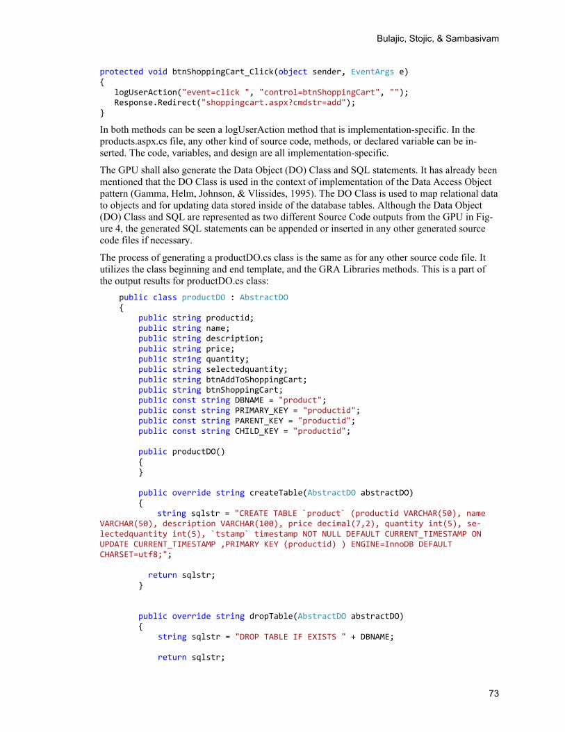
The GPU shall also generate the Data Object (DO) Class and SQL statements. It has already been mentioned that the DO Class is used in the context of implementation of the Data Access Object pattern (Gamma, Helm, Johnson, & Vlissides, 1995). The DO Class is used to map relational data to objects and for updating data stored inside of the database tables. Although the Data Object (DO) Class and SQL are represented as two different Source Code outputs from the GPU in Fig-ure 4, the generated SQL statements can be appended or inserted in any other generated source code files if necessary.
The process of generating a productDO.cs class is the same as for any other source code file. It utilizes the class beginning and end template, and the GRA Libraries methods. This is a part of the output results for productDO.cs class:
public class productDO : AbstractDO { public string productid; public string name; public string description; public string price; public string quantity; public string selectedquantity; public string btnAddToShoppingCart; public string btnShoppingCart; public const string DBNAME = "product"; public const string PRIMARY_KEY = "productid"; public const string PARENT_KEY = "productid"; public const string CHILD_KEY = "productid"; public productDO() { } public override string createTable(AbstractDO abstractDO) {
string sqlstr = "CREATE TABLE `product` (productid VARCHAR(50), name VARCHAR(50), description VARCHAR(100), price decimal(7,2), quantity int(5), se‐lectedquantity int(5), `tstamp` timestamp NOT NULL DEFAULT CURRENT_TIMESTAMP ON UPDATE CURRENT_TIMESTAMP ,PRIMARY KEY (productid) ) ENGINE=InnoDB DEFAULT CHARSET=utf8;"; return sqlstr; } public override string dropTable(AbstractDO abstractDO) { string sqlstr = "DROP TABLE IF EXISTS " + DBNAME; return sqlstr;
73

Requirement Validation with Automatically Generated Program Code
} public override AbstractDO getClassName() { return new productDO(); }
Besides each field declaration, in this class are the methods and SQL statements that support CRUD operations.
A detailed description of this class does not make sense because the GPU employment as well as templates and the GRA Library methods are implementation-specific. The implementation pre-sented in this section is the author’s own design, and this implementation is created for research and experiment purposes. How the requirement description will be structured and where it will be stored is implementation-specific.
Automatically Generated Source Code Validation The automatically generated source code is validated by:
Compiler Runtime environment
Using the compiler and runtime environment for automatically generated code validations fits well into the GRA's basic philosophy to reuse already available technical platform features to reduce the amount of the work.
The source code generated by the GRA Framework is immediately available for the MS Visual Studio Express 2012 for the Web, and the GRA Framework tries to execute generated source code. When the generated code is requested the MS Visual Studio compiles it automatically. The ASP.NET/C# compiler will check syntax and semantics, parsing and preprocessing, and report any kind of compiler errors. If there is a compiler error, such as an undefined variable or reference to an undeclared class or method, the user may be able to correct it by changing requirement descriptions in the GRA Framework. The requirement description can be changed through the Designer as it is described in Figure 3.
Compiler errors can be related to using the wrong MS Visual Studio version or missing an installation of the Microsoft .NET framework. Such kinds of errors should be corrected by installation of the missing software.
If compilation is accomplished successfully, then the ASP.NET Development Server, the Web server delivered as a part of the MS Visual Studio installation package, executes the generated source code.
The Client accesses the application code using a Web Browser. When the code is executed, a runtime error can occur. The runtime errors are usually related to an improper technical platform software installation or to corrupted database files or configuration files. The runtime environ-ment will report any runtime error inside the Web Browser.
One example of runtime error is missing the connection to the database, see Figure 4. The missing connection can be caused by an incorrect installation of the database software or by using the wrong API calls. For example, if the database is a Oracle MySQL 5.6.10 database, then ASP.NET requires installation of the Oracle MySQL Connector NET version 6.6.5.
74

Bulajic, Stojic, & Sambasivam
Demonstrate Working Software during Requirement Negotiations Process Generating source code for each particular object would not be a sufficient way to demonstrate the software application. Before it is possible to demonstrate a working application, the source code needs to be compiled and linked. These tasks can be automated using scripting languages, such as UNIX shell script, Windows Power Schell, or the Python languages. Another solution is to use Web-related technologies, such as JavaScript or ASP.NET and Web browsers, as runtime environments.
Even though the application can be executed, the interactive application requires implementation of navigation menus and action buttons that can send data to processing inside of the application and return a processed result. This kind of feature requires implementation of common libraries that contain a common set of functions that can be applied to a particular class of objects. For example, the class of Forms object could require a button that can save the form’s data to perma-nent storage, and then retrieve and modify saved data.
Provide Collaborative Environment The collaborative environment in the Internet era requires data- and information-sharing between stakeholders anytime and anywhere. This is important in the distributed development environ-ment when software is created by multiple distributed development teams that can be located in different countries, on different continents, and in different time zones.
Data- and information-sharing is not readily sufficient yet, and collaborative environments need to be able to provide data, information history, and automatic notification in case of any data or information changes.
The history of changes can be managed by versioning or by a design that prevents modification and deletion of existing data and information and supports adding changes.
Automatic notification can be implemented as automatic mail to stakeholders. “Automatic mail notifications are a powerful tool for information-sharing and distribution, and can save a lot of time spent on writing and answering emails, and significantly reduce communication overhead. Besides informing stakeholders that a requirement has been changed, a mail message contains all the details about the change. While creating such a message is an easy job for a computer, for a human being this can be a daunting and error-prone task that can take a lot of time, and remove focus and affect creativity, effectiveness, and productivity” (Bulajic, Sambasivam, & Stojic, 2013:23).
Retail Store Example Application The GRA Framework is used for the development of a fictive application called Retail Store. The Retail Store application is an E-commerce application and is implemented as a Web application for a product’s online sales. The Retail Store application requirements are described by fictive User Stories. The Retail Store User is a general description of the application requirements, and Salesman and Buyer User Stories provide more detailed requirements information.
The Retail Store User Story:
“As the Retail Store we want to sell our products online through the Internet in order to increase product availability, get in touch with more customers, and increase sales and profit”.
75

Requirement Validation with Automatically Generated Program Code
The Salesman User Story:
“As a Salesman I need to be able to add a product to the product list for sale, update products, and remove products from the product list in order to enable product online sales and keep in-formation such as product description, price, and available quantity up-to-date”.
The Buyer User Story:
“As a Buyer I need to be able to: * select a product * enter a desired product quantity * add a product to the shopping cart * review and update a shopping list * provide a delivering address and make shipping choices * purchase a product using a credit card
in order to select the best price and delivery conditions”.
Each of these User Stories can be described in more detail by Use Cases and Test Cases, but it would draw attention away from the proposed GRA method. The purpose of the Retail Store ex-ample is to demonstrate how the GRA collects requirements and create executables for require-ment demonstration.
Figure 5. Product Component
76
Bulajic, Stojic, & Sambasivam
From the Retail Store User Story can be identified:
A ProductComponent object A Sales Operation.
Although a Product from the design point of view can be considered a single object, in case of the GRA Framework it is designed as a collection of objects. Using the name ProductComponent makes it clear that a product is a collection of objects. Aside from data component and methods, to the ProductComponent can be assigned User Stories, Use Cases and Test Cases, and Forms that will visualize a Product and enable the interactive methods’ execution. The number of ob-jects that can be assigned to the Product Component are not limited and any number of Test Cases can be designed; for example, how the Product will be represented is a Designer choice and this is only an example. The Product can be represented by the User Story object, and the User Story node can be attached to the Use Cases, Test Cases, and Forms children. The GRA Frame-work does not introduce any limitations.
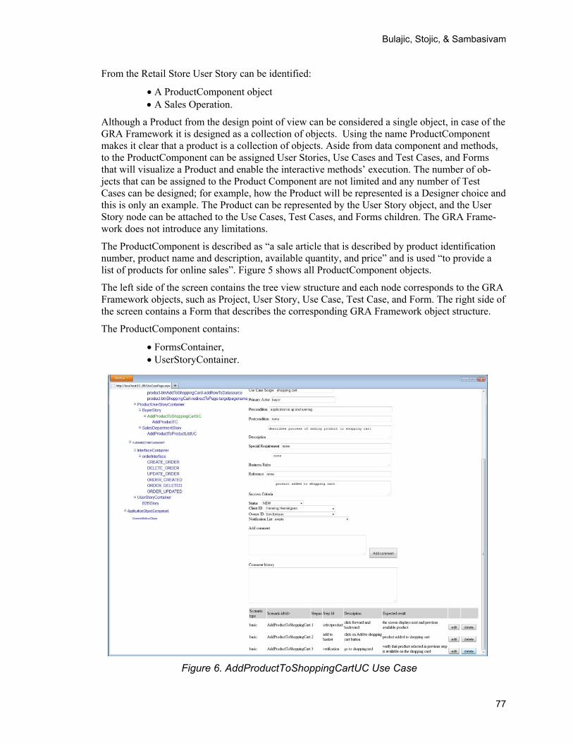
The ProductComponent is described as “a sale article that is described by product identification number, product name and description, available quantity, and price” and is used “to provide a list of products for online sales”. Figure 5 shows all ProductComponent objects.
The left side of the screen contains the tree view structure and each node corresponds to the GRA Framework objects, such as Project, User Story, Use Case, Test Case, and Form. The right side of the screen contains a Form that describes the corresponding GRA Framework object structure.
The ProductComponent contains:
FormsContainer, UserStoryContainer.
Figure 6. AddProductToShoppingCartUC Use Case
77

Requirement Validation with Automatically Generated Program Code
These two containers are used for storing Form design information, User Story, SalesDepart-mentStory, and AddProductToShoppingCartUC Use Case.
In the SalesDepartmentStory are described the Sales Department and Salesman expectations:
“As a Salesman I need to be able to add a product to the product list for sale, update a product, and remove a product from the product list in order to enable products’ on-line sales and keep information such as product description, price, and available quantity up-to-date”.
This User Story is described in more detail with a AddProductToProductListUC Use Case. The Use Case is a child node of the User Story, but the Use Case can be moved to its own container and to each Use Case can be assigned a link that points to the corresponding User Story or Com-ponent, or any other Object. In this Framework version, there are implemented links to the parent node and descriptions. Figure 6 illustrates a Use Case template and guidelines and uncovers more details about the Product object:
In the AddProductToShoppingCartUC Use Case figure are all the steps and the order of execution to add a product to the shopping list. The Use Case object is a template and guideline for creating a Use Case. The Framework enables adding a new step, or updating or deleting any existing step features.
Figure 7. AddProductTC Test Case
78

Bulajic, Stojic, & Sambasivam
The AddProductToShoppingCartUC Use Case purpose is the clarification of the requirements described in the parent node, the BuyerStory:
Figure 7 illustrates the Test Case template and guidelines:
The Test Case template and guidelines provides information about the Test Case’s purpose as well as describing details about each Test Case step.
The Test Case and Test Case step objects provide a standard set of database operations such as insert, update, delete, and search. Here it is possible to copy a Test Case or Test Step by changing the ID and Use Save option. This is a feature generally available for all Framework objects.
Figure 8 illustrates Test Case template and guidelines:
Figure 8. AddProductTC Test Step
The GRA Framework enables adding, moving, and deleting of each object or node. Deleting a node will not delete the node’s description. The node description will still exist and can be reused by another node. This is an implementation-specific feature.
The ProductComponent contains the FormsContainer node. While the previously mentioned ob-jects are used for design and documenting purposes, the Forms object is used by the Code Gen-erator to generate source code and executables. Figure 9 illustrates the Forms objects template and guidelines:
79

Requirement Validation with Automatically Generated Program Code
.
Figure 9. ProductForms Forms
The details about using the ProductForms form’s data for generating source code are explained in Figure 4 in the “Generate Source Code without Manual Programming” section.
Each of the Form’s fields is able to assign an action. The actions can be a validation of a field type, execution of a piece of code, a call to internal and external procedures, redirection of the application flow, an execution of the request for form’s data processing, or any other kind of ac-tion that can be executed via the source code. The Application Object is responsible for the ac-tion. The Application Object belongs to the GRA Framework’s objects responsible for storing data in structured text format that are used to generate source code, and the Application Objects are responsible for backend or batch job processing. Each of the Application Objects is repre-sented by a corresponding class and class methods.
The Code Generator is responsible for adding code to each forms field, and the code is executed when the event on that field is fired. This is a straightforward process and is guided by the Appli-cation Object. If the Code Generator needs to add code to the form’s field, then the Application Object class and method code should already exist. The Retail Store application uses a GenericMethodClass Application Object and the GenericMethodClass methods:
addRowToDatasource – adds a current object’s data to the output data source mathFormula – is used for math operations redirectToPage – used for moving workflow to the next Web page
80

Bulajic, Stojic, & Sambasivam
sqlMathExpression – used in cases when calculations are executed by using SQL statement and data is stored in the database table
updateRowToDatasource – used to update rows in the database by using the current object data
Generating Source Code and Executables Generated source code and executables are directly dependent on the validation results. The forms are used for requirement visualization, test, and validation of the product features. The generated source code and executables are used for requirement validation and any further work.
For example, the mathFormula assigned to the orderdemo forms total field, is described as “item-stotal + handlingfee + ( itemstotal + handlingfee ) * vatamount / 100”
If any of the operands is missing, the compiler will issue an error.
If any operand contains an illegal value, such as null value, the compiler will issue an error.
If everything is all right, then executables will enable the testing of math formula. The user will be able to assign different values to each or a selected number of operands and to inspect the dis-played calculation result.
To enable validation it is necessary to generate source code and executables. This job is accom-plished by the Code Generator. The Code Generator reads each piece of the Framework’s object design information stored in the database and translates it to the C# source code. Before the gen-erator is involved the GRA Framework object and code generator options must be selected. The Code Generator is involved with a single click on the Generate Code button.
Figure 10 illustrates this button’s position and options:
Figure 10. Generate Code
In the dropdown list are available options for creating code_only, code_and_datasource, datasource_only, or for altering the code and data source.
When the Forms is selected and generated, the Framework will redirect workflow to the last gen-erated page. Figure 11 illustrates the Generate Code result:
81

Requirement Validation with Automatically Generated Program Code
Figure 11. Product Forms Generated
On the left-side of the screen is the navigation tree that shows all the generated objects. On the right screen panel is the latest generated form.
The GRA Framework’s job is accomplished when the source code and executables are generated. The GRA Framework provides a working application and requirement demonstration. The team responsible for requirement negotiation can use the generated application for requirement testing and tuning.
The generated forms are fully functional applications. On the top of the product forms are previ-ous (“<”) and next (“>”) navigation buttons, as well as “Save” and “Delete” buttons. The “Save” button has attached to it “insert” and “update row” functions. If a row already exists it will be updated; otherwise, it will insert a new row. To the “Add to ShoppingCart” function is assigned a generic method addRowToDatasource and to the “Shopping Cart” button is assigned a redi-rectToPage method. The “redirectToPage” method assigned to the “Shopping Cart” button is a generic method that can be used to test application workflow.
82

Bulajic, Stojic, & Sambasivam
Summary of GRA Features and Comparison to other Approaches
The GRA Framework presented in this paper simplifies the task of development’s environment setup, and the implementation presented in this paper—besides a Web server and the GRA Framework Web application installation—requires installation of the MySQL database. The GRA Framework and runtime environment can be quickly established and used during require-ments negotiation.
The GRA Framework does not require manually writing source code. The code is already written and is a part of the GRA Framework’s templates and libraries.
The requirement description is guided by the GRA Framework’s objects and object attributes, and these guidelines ensure there is a sufficient level of detail for each requirement’s description. A sufficient level of detail is represented by the Framework’s predefined set of objects and object attributes. These attributes create the parameters for specifying the sufficient number of details.
The GRA Framework’s object functionality supports the negotiation process and demonstrates the solution. This demonstration is different from prototyping because it does not require estab-lishing either a development environment or development team, nor does it require the writing of code. The demonstration is created on demand and is a part of the Framework.
The demonstration is based on the data provided by the requirement negotiation parties. Each demonstration is documented by the negotiation process participants, and executables are the product of the requirements that are described using the customer’s language.
Using the customer language is an important motivation for the customer’s active involvement. The customer can follow the process, make decisions, and test those decisions.
Although the customer’s active involvement is important for a project’s success, it is an unrealis-tic expectation that the customer will be available all the time. The customer has his or her own job and responsibilities. A customer’s motivation and interest in the project are best at the begin-ning. Despite that the first releases can be interesting to a customer, every subsequent release causes a decrease in motivation and interest, and the amount of lost motivation is proportional to the number of defects and customer-specific amount of work. A customer’s interest is refreshed when the project approaches its deadline in expectation of the final release.
To be able to participate actively, a customer should understand the process and language. This is the reason why the Framework utilizes the common language, but not scripts or technical nota-tions.
A predefined set of generic objects included in the Framework eliminates the need for writing code during the requirement negotiation process. Once the requirement’s negotiation process starts, any break or interruption can affect the flow, decreasing motivation and turning the nego-tiations off-course. Sometimes even a lunch break can be enough. What might happen if negotia-tions need to wait weeks or a month before a software release is available?
The experience collected during the GRA Framework’s development shows that the creation of a new generic object speeds up if there are already generic objects available. The generic object’s programming increases object reusability and promotes the design of reusable classes and meth-ods. The new generic object reuses existing features, classes, and methods.
83

Requirement Validation with Automatically Generated Program Code
Software Development Method Generalized Requirement Approach (GRA) vs. Prototyping While it can be argued that prototyping is already well established and the GRA has some simi-larities, the GRA is significantly different.
While a prototype is developed in a separate development process by programmers, the GRA generates the working application during the requirement negotiation process together with the customers.
While a prototype is developed by writing source code in a computer-specific programming lan-guage, the GRA generates source code from specifications described in the customer’s native language.
While the prototype development can take weeks or months to accomplish, the GRA-generated source code and executables can be available immediately during requirement negotiation.
Software Development Method Generalized Requirement Approach (GRA) vs. Visual Modeling While visual modeling is based on the diagrams and relations between the diagrams that are translated to executable code, the current method is based on the data-driven development method, and the visual design representation is generated from the requirement’s structured text descriptions.
While visual modeling uses a complex notation, the GRA uses plainer customer-oriented lan-guage. The customer decides what terminology will be used.
While in case of visual Modeling, visualize Design is one of the first steps of the software devel-opment process, immediately after requirement elicitation, in the GRA the requirement elicitation is an iterative process that involves the requirement description and requirement validation cy-cles.
Software Development Method Generalized Requirement Approach (GRA) vs. Formal System Development Methodology A formal specification is usually written in a concrete language that has a precisely defined syn-tax and semantics (Wing, 1988). A formal specification is executed by a machine-executable interpreter, like Prolog or Lisp.
The Formal System Development methodology is based on the systematical formal mathematical transformations of requirements into more detailed mathematical representations that are finally converted into an executable program.
The GRA is not based on any systematical formal mathematical transformations nor is it lan-guage-specific, despite that it can generate a language-specific source code. The GRA is not de-scribed by mathematical formulas, but rather by definitions that are expressed in the customer’s language.
Software Development Method Generalized Requirement Approach (GRA) vs. Rapid Prototyping Even though there are many similarities between rapid prototyping and the GRA, there are also many important differences.
84

Bulajic, Stojic, & Sambasivam
The GRA does not require manual code writing. The rapid prototype is usually created by drag-ging and dropping controls into the forms, setting control properties and events, and manual writ-ing the source code. This is not a part of the GRA. The GRA works with already predefined com-ponents and controls and does not write any source code manually. While rapid prototyping uses a computer language-specific code for creating executables, the GRA uses a customer’s language and structured text description.
While using rapid prototyping, the developers, programmers, designers, and IT professionals are all involved in creating executable applications and writing code. In the GRA, executables are created in the background, and the person who creates the executables does not have to be aware of how it is done, nor what kind of software is used.
Conclusion The Generalized Requirement Approach proposed in this paper can improve software develop-ment productivity, and improve the quality of the final product. This paper addresses the follow-ing requirement negotiation issues:
the IKIWISI (“I’ll know it when I see it”) Syndrome the Yes, But (“That is not exactly what I mean”) Syndrome the Undiscovered Ruins (“Now that I see it, I have another requirement to add”)
Syndrome an insufficient level of details specification
The GRA Framework (the implementation of the GRA) utilizes object attributes as guidelines for specifying requirements and providing the sufficient level of detail. The data stored in the prede-fined set of objects is described by the customer’s native language. The generic programming units (GPUs), part of the GRA Framework, are able to generate a working application example from the requirement specification data stored in the GRA Framework’s objects.
The result of the experiment, the example application, demonstrates the feasibility of the pro-posed solution and shows that the predefined set of the Framework’s objects and code that uses data defined during the requirement negotiation process is sufficient for generating source code and a working application without the need for writing code manually.
The generated executables are fully functional applications that can be executed and tested ac-cording to the requirement description. The Retail Store demo application demonstrates the work-flow, data quality, algorithms, and can be used for ad-hoc testing.
According to the currently collected experience, the critical part of this approach is providing a sufficient amount of the features that are in the GRA represented by the Application Object. The Application Object represents the classes and generic methods that solve a particular program-ming issue. For example, it can be the testing of a unique ID, moving rows from one relation table to another, or creating new entities that are combinations of the existing ones. In the Retail Store demo application example, such features are provided by the methods stored in the GenericMethodClass. For example, the addRowToDataSource generic method is able to add cur-rent data source rows to any other data source that is specified in the method’s parameters.
The primary purpose of the solution proposed in this paper is requirement clarification. The ex-periment with the example application is sufficient to create proof of concept, but it is not suffi-cient to make a final conclusion about the GRA’s potential. For a final conclusion, the proposed software development method improvement based on the GRA needs to be tested on a full-scale basis with industrial projects.
85

Requirement Validation with Automatically Generated Program Code
This Framework version has been developed for research and experiment purposes. Further de-velopment can create a product that not only benefits requirement negotiations, but can be used for estimation, and for project management purposes.
The GRA’s limitations are related to the non-functional requirements, such as performances, se-curity, and robustness. The GRA is not suited for non-functional requirements. While generating source code can be a good starting point for further application software development, the source code generated by the Framework is not optimized. Data normalization, code optimization, and security, according to this method, are moved to the next step where the developer specialist and experts for these kind of tasks are involved.
The same is valid for database design. The data model is not normalized and using a not-normalized data model is preferable because it simplifies writing about generic methods. The GRA-created data model cannot be used in a production environment and needs normalization, indexing, and performance tuning.
The implementation of the proposed model is not a simple task and requires experienced devel-oper knowledge. The generic methods are more difficult to debug. Using abstract classes and interfaces can make the code obscure and hide implementation.
References Beck, K. (2002a). Introduktion til extreme programming. IDG Forlag A/S. ISBN: 87-7843-509-9.
Beck, K. (2002b). Test driven development by example. Addison-Wesley.
Beck, K., Beedle, M., van Bennekum, A., Cockburn, A., Cunningham, W., Fowler, M., . . . Thomas, D. (2001a). Manifesto for agile software development. Retrieved from http://agilemanifesto.org/
Beck, K., Beedle, M., van Bennekum, A., Cockburn, A., Cunningham, W., Fowler, M., . . . Thomas, D. (2001b). Principles behind the Agile Manifesto. Retrieved from http://agilemanifesto.org/principles.html
Benington, H. D. (1956). Production of large computers programs. Presented at the Symposium on Ad-vanced Programming Methods for Digital Computers sponsored by the Navy Mathematical Computing Advisory Panel and the Office of Naval Research, June 1956. Retrieved from http://csse.usc.edu/csse/TECHRPTS/1983/usccse83-501/usccse83-501.pdf
Bulajic, A., Sambasivam, S., & Stojic, R. (2013). An effective development environment setup for system and application software. Issues in Informing Science and Information Technology, 10, 37-66. Re-trieved from http://iisit.org/Vol10/IISITv10p037-066Bulajic0086.pdf
Bulajic, A., Stojic, R., & Sambasivam, S. (2013a). Gap between service requestor and service provider. Paper presented at the International Conference on Applied Internet and Information Technologies. Zrenjanin, Serbia, October 26, 2013.
Bulajic, A., Sambasivam, S., & Stojic, R. (2012). Overview of the test driven development research pro-jects and experiments. Proceedings of the Informing Science and Information Technology Education 2012 Conference (InSITE) in Montreal, Canada, June 22-27, 2012. Retrieved from http://proceedings.informingscience.org/InSITE2012/InSITE12p165-187Bulajic0052.pdf
Cockburn, A. (2008). Using both incremental and iterative development. CROSSTALK The Journal of Defense Software Engineering, May, 27-30. Retrieved from http://www.crosstalkonline.org/storage/issue-archives/2008/200805/200805-Cockburn.pdf
DragonPoint Inc (2008). Requirements capture: Keys 6 through 10 to a successful software development project. Company Newsletter issue No. 3,. Retrieved from http://www.dragonpoint.com/CompanyNewsletters/RequirementsCaptureKeys610.aspx
Eveleens, L. J., & Verhoef, C. (2010). The rise and fall of the chaos report figures. IEEE Software, Janu-ary/February.
86

Bulajic, Stojic, & Sambasivam
Frincke, D., Wolber, D., Fisher, G., & Cohen, G. C. (1992). Requirements Specification Language (RSL) and supporting tools. NASA Tech Docs, NASA.
Gamma, E., Helm, R., Johnson, R., & Vlissides, J. (1995). Design patterns: Elements of reusable object-oriented software. Boston: Addison-Wesley.
IBM. (2007). IBM project management. Retrieved from http://facweb.cs.depaul.edu/yele/Course/IS372/Guest/Dawn%20Goulbourn/IBM%20PM%20presentation%20for%20DePaul.ppt
IBM. (n.d.). Rational SDL Suite: Improve SDL software development for communications systems. Re-trieved from http://www-03.ibm.com/software/products/en/ratisdlsuit/
Larman, C. (2005). Applying UML and patterns. Pearson Education.
Leffingwell, D., & Widrig, D. (2000). Managing software requirements : A unified approach. Addison-Wesley.
Microsoft. (2003). Microsoft Solution Framework 3.0 Overview: Microsoft solution framework white pa-per. Retrieved from http://www.microsoft.com/en-us/download/details.aspx?id=13870
Royce, W. W. (1970). Managing the development of large software systems. Proceedings of IEEE WES-CON 26, August 1970. Retrieved from http://www.cs.umd.edu/class/spring2003/cmsc838p/Process/waterfall.pdf
Sommerville, I. (2001). Software engineering (6th ed.). Pearson Education Limited
The Standish Group (1995). Chaos report. Retrieved from http://net.educause.edu/ir/library/pdf/NCP08083B.pdf
The Stanford Natural Language Processing Group. (n.d.). Retrieved from http://nlp.stanford.edu/
Sutherland, J., & Schwaber, K.(2011). The Scrum papers: Nuts, bolts, and origins of an agile framework. Retrieved from http://scruminc.com/tl_files/scrum_inc/documents/ScrumPapers.pdf
Tse, T. H., & Pong, L (1991). An examination of requirements specification languages. Department of Computer Science, The University of Hong Kong, 1991, available at http://citeseerx.ist.psu.edu/viewdoc/summary?doi=10.1.1.14.6414
Wiegers, K. E. (2003). Software requirements. Redmond, Washington: Microsoft Press.
Wing, J. M. (1988). A study of 12 specifications of library problem. Carnegie Mellon University, IEEE Software, 0740-7459/88/0700/0066,1988
Biographies Aleksandar is working more than twenty five years as a computer expert and consultant for some of the top companies in the world.
Aleksandar Bulajic is PhD Candidate at Faculty of Information Tech-nology, Metropolitan University. He graduated from the University of Liverpool, with a Master’s in Science degree (Cum Laude) in Informa-tion Technology, and from the Economic University with a Bachelor’s (BA) degree.
His papers and articles were published in journals and at several inter-national IT conferences in USA, Canada, France, India, Nigeria, Ser-bia, Portugal and Australia. He wrote and published several novels and a stage play, and is working on screenplay manuscripts. Besides his professional work and writings, his current interests and writings are
mostly related to film and theatre and interdisciplinary multimedia experiments. He is a member of Liverpool University Alumni Community and Informing Science Institute.
87

Requirement Validation with Automatically Generated Program Code
88
Dr. Samuel Sambasivam is Chairman and Professor of the Computer Science Department at Azusa Pacific University. His research interests include optimization methods, expert systems, client/server applications, database systems, and genetic algorithms. He served as a Distinguished Visiting Professor of Computer Science at the United States Air Force Academy in Colorado Springs, Colorado for a year. He has conducted extensive research, written for publications, and delivered presentations in Computer Science, data structures, and Mathematics. He is a voting member of the ACM and is a member of the Institute of Electrical and Electronics Engineers (IEEE).
Radoslav Stojic has a thirty years experience on software develop-ment, testing and certification in European aeronautic industry.
He has been working on research and development projects ranging from FBW flight control to walking robots and flight simulators.
He is currently teaching software quality and testing, artificial intelli-gence and software for computer games at Faculty of Information Technology at Belgrade.