the generation iv gas cooled fast reactor · 3 why have gas cooled fast reactors ? fast reactors...
TRANSCRIPT

The Generation IV Gas Cooled Fast Reactor
Dr Richard Stainsby
AMEC
Booths Park, Chelford Road, Knutsford,
Cheshire, UK, WA16 8QZ
Phone: +44 (0)1565 684903, Fax +44 (0)1565 684876
e-mail: [email protected]

2
Contents
1. Why have fast gas cooled fast reactors ?
2. The GFR system
3. Performance requirements for the Gen IV GFR system
4. Specific challenges
5. Decay heat removal
6. GFR Safety systems
7. Risk minimisation
8. Conclusions

3
Why have gas cooled fast reactors ?
Fast reactors are important for the sustainability of nuclear power:
More efficient use of fuel
Reduced volumes and radiotoxicity of high level waste
Sodium cooled fast reactors are the shortest route to FR deployment, but:
The sodium coolant has some undesirable features:
– Chemical incompatibility with air and water
– The strongly positive void coefficient of reactivity
– Avoiding sodium boiling places a restriction on achievable core outlet temperature.
Gas cooled fast reactors do not suffer from any of the above:
Chemically inert, void coefficient is small (but still positive), single phase coolant eliminates
boiling.
But …
Gaseous coolants have little thermal inertia – rapid heat-up of the core following loss of
forced cooling;
– Compounded by the lack of thermal inertia of the core structure + very high power
density
Motivation is two-fold: enhanced safety and improved performance (c.f. SFR)
4
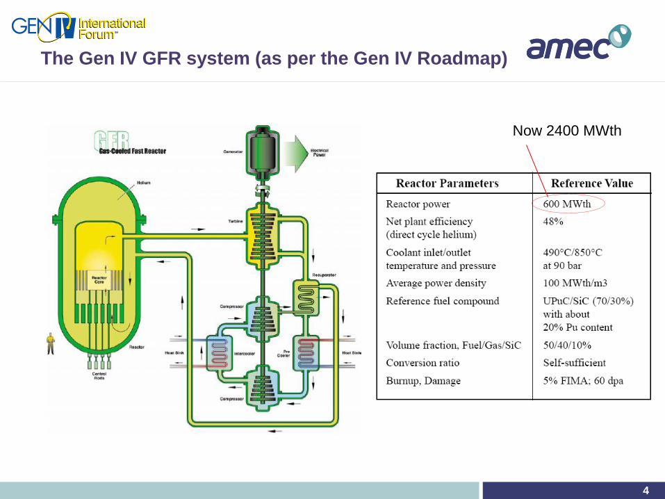
The Gen IV GFR system (as per the Gen IV Roadmap)
Now 2400 MWth
5
Current concept - Gas~Steam turbine combined cycle
Indirect steam cycleIndirect SC CO2
cycle
Indirect
combined cycle
Direct He Brayton
cycle
He
H2O hp
He-N2
He
He CO2s
H2O He
Indirect steam cycleIndirect SC CO2
cycle
Indirect
combined cycle
Direct He Brayton
cycleIndirect steam cycle
Indirect SC CO2
cycle
Indirect
combined cycle
Direct He Brayton
cycle
He
H2O hp
He-N2
He
H2O hp
He-N2
He
He CO2s
H2O He
reactor
primary
circulator
main heat
exchanger
He-N2 turbine
Heat recovery steam
generator
He-N2
compressor
feed pump
steam turbine
condenser
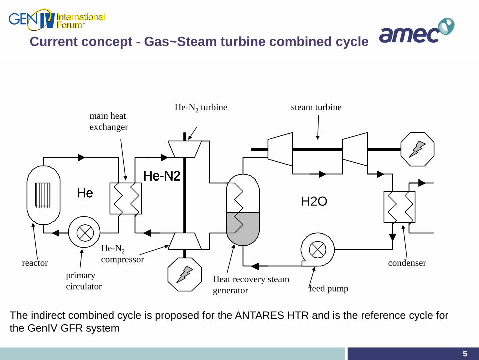
The indirect combined cycle is proposed for the ANTARES HTR and is the reference cycle for
the GenIV GFR system

6
Cut-away view of a proposed 2400 MWth
indirect-cycle GFR
re-fuelling
equipment
core control and shutdown
rod drives
steel reactor pressure
vessel
core barrel
main heat exchanger
(indirect cycle)
Decay heat
removal heat
exchanger

7
GFR Performance requirements
Self-generation of plutonium in the core to ensure uranium resource
saving.
Optional fertile blankets to reduce the proliferation risk.
Limited mass of plutonium in the core to facilitate the industrial
deployment of a fleet of GFRs.
Ability to transmute long-lived nuclear waste resulting from spent fuel
recycling, without lowering the overall performance of the system.
Favourable economics owing to a high thermal efficiency.
The proposed safety architecture fits with the objectives considering
the following elements:
Control of reactivity/heat generation by limiting the reactivity swing over the
operating cycle; the coolant void reactivity effect is minor.
Capacity of the system to cool the core in all postulated situations,
provision of different systems (redundancy and diversification).
A “refractory” fuel element capable of withstanding very high temperatures
(robustness of the first barrier and confinement of radioactive materials).

8
Specific Challenges (1): Fuel
The greatest challenge facing the GFR is the development of robust
high temperature refractory fuels and core structural materials,
Must be capable of withstanding the in-core thermal, mechanical and
radiation environment.
Safety (and economic) considerations demand a low core pressure drop,
which favours high coolant volume fractions.
Minimising the plutonium inventory leads to a demand for high fissile
material volume fractions.
Candidate compositions for the fissile compound include carbides,
nitrides, as well as oxides.
Favoured cladding materials include:
refractory metals and SiC for pin formats
refractory metals and ceramic matrices (e.g. SiC, ZrC, TiN) for dispersion
fuels in a plate format

9
Potential GenIV GFR fuel forms
Ceramic plate
Ceramic pin
e

10
Specific challenges (2): Decay heat removal (DHR)
HTR “conduction cool-down” will not work in a GFR
High power density, low thermal inertia, poor conduction path and small
surface area of the core conspire to prevent conduction cooling.
A convective flow is required through the core at all times;
A natural convection flow is preferred following shutdown
–This is possible when the circuit is pressurised
A forced flow is required immediately after during when depressurised:
–Gas density is too low to achieve enough natural convection
–Power requirements for the blower are very large at low pressure
The primary circuit must be reconfigured to allow DHR
Main loop(s) must be isolated
DHR loop(s) must be connected across the core
Conclusion: the reliability of the DHR function is dependent on the
reliability of the primary circuit valves.

11
Schematic diagram of the DHR system in natural
convection mode
Exchanger #2
pool
Exchanger #1
core
Secondary loop
dedicated DHR loops
H1
H2
guard
containment

12
Primary circuit components configured in DHR mode
.
D P core
main
circulator
closed
check valve
open
DHR
check
valve
DHR heat
exchanger
DHR circulator
(or natural circulation)
D P core
reactor
main heat
exchanger
1200 °C

13
Depressurised DHR
For depressurised conditions, it would always be possible to generate
enough flow through the core using a large enough fan.
If the primary circuit has depressurised to atmospheric pressure, the
power consumption is very large and the duration could be very long
Proposed solution is to surround all the primary circuit components by
another pressure vessel (known as the guard containment).
Pressure within the guard containment would be controlled such that;
After the LOCA, a minimum pressure of 10 bar remains within the primary
circuit.
This back pressure allows the power of the DHR fan to be low enough to
be supplied by batteries for the first 24 hours, afterwards, the decay heat
power is low enough for natural convection to cope.
The back pressure is a compromise between the performance and
power requirements of the DHR fan and the structural complexity of
the guard vessel.

14
2400 MWth indirect-cycle GFR inside a spherical
“guard vessel”

15
Reactor building

16
GFR Safety systems – Shutdown
Requirement for rapid and reliable shutdown systems
The system cannot tolerate an unprotected loss of flow – even with ceramic
clad fuel.
Two levels of shutdown are incorporated in the current concept, both based
on absorber rods (CSD + DSD)
A rapid, diverse, and preferably passive, third level shutdown system is
being considered required (e.g. injection of a liquid or particulate absorber
into dedicated core elements)
17
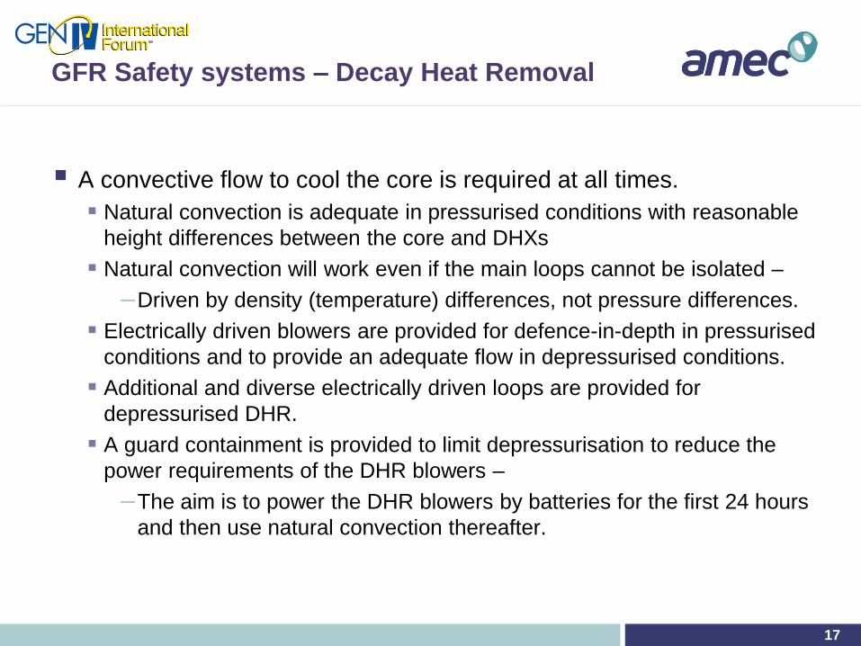
GFR Safety systems – Decay Heat Removal
A convective flow to cool the core is required at all times.
Natural convection is adequate in pressurised conditions with reasonable
height differences between the core and DHXs
Natural convection will work even if the main loops cannot be isolated –
–Driven by density (temperature) differences, not pressure differences.
Electrically driven blowers are provided for defence-in-depth in pressurised
conditions and to provide an adequate flow in depressurised conditions.
Additional and diverse electrically driven loops are provided for
depressurised DHR.
A guard containment is provided to limit depressurisation to reduce the
power requirements of the DHR blowers –
–The aim is to power the DHR blowers by batteries for the first 24 hours
and then use natural convection thereafter.
18
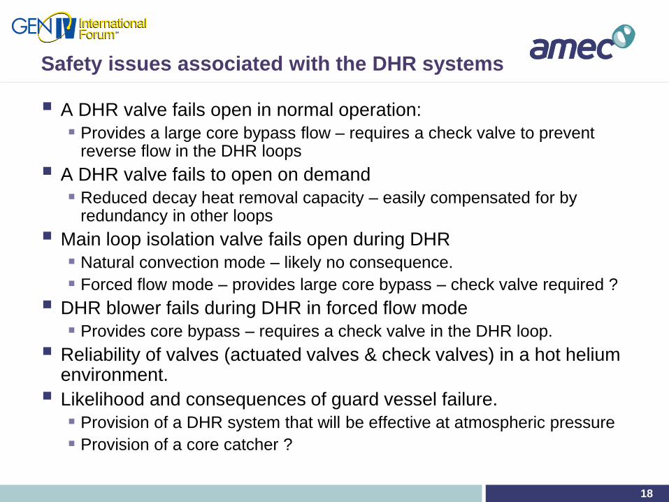
Safety issues associated with the DHR systems
A DHR valve fails open in normal operation:
Provides a large core bypass flow – requires a check valve to prevent reverse flow in the DHR loops
A DHR valve fails to open on demand
Reduced decay heat removal capacity – easily compensated for by redundancy in other loops
Main loop isolation valve fails open during DHR
Natural convection mode – likely no consequence.
Forced flow mode – provides large core bypass – check valve required ?
DHR blower fails during DHR in forced flow mode
Provides core bypass – requires a check valve in the DHR loop.
Reliability of valves (actuated valves & check valves) in a hot helium environment.
Likelihood and consequences of guard vessel failure.
Provision of a DHR system that will be effective at atmospheric pressure
Provision of a core catcher ?

19
Risk Minimisation
Improvement of passive reactivity control and introduction of a tertiary shutdown system
Exploitation of control rod driveline expansion –
–current concepts have control rods pushed out of the core from below – simple driveline expansion may give positive feedback on reactivity
–Methods of reducing driveline length on heat-up could be devised.
Passive introduction of absorber as a tertiary shutdown system
Reduction in number or elimination of valves in the DHR system
Problem is that the DHR systems (and main loops) are connected in parallel, so adding more loops will degrade the reliability if failed loops cannot be isolated.
The natural convection mode is more reliable in this respect.
Introduction of fluidic valves (with no moving parts) is a possibility.
Heavy gas injection as a decay heat removal mechanism
Provides motive force through momentum and negative bouyancy
Replacement of helium following a LOCA will allow natural convection cooling to be established more quickly.

20
Conclusions
Motivation behind GFR is to develop a fast reactor system that is free
of the worst problems associated with sodium:
Coolant void coefficient
Chemical reactivity
Opacity
The trade-off is a system that has negligible thermal inertia, so
shutdown and decay heat removal are the main safety issues
GFR has traded the a reduced likelihood of a whole core disruptive
accident for an increased likelihood of core melt.
The safety systems must therefore be able to guarantee shutdown and to
provide a positive flow of coolant through the core.
Tertiary shutdown and reliable depressurised DHR are considered to
be the main safety challenges.