the globe valves are used as a closing valve · pdf filethe globe valves are used as a closing...
TRANSCRIPT

The globe valves are used as a closing valve for: - noncorrosive fluids - saturated steam - oil - air - petroleum and petroleum productsThe Characteristics of working conditions:pressure dependency on temperature according to ASME B 16.34.
technical description:technical description:
construction:
designed dimensions:
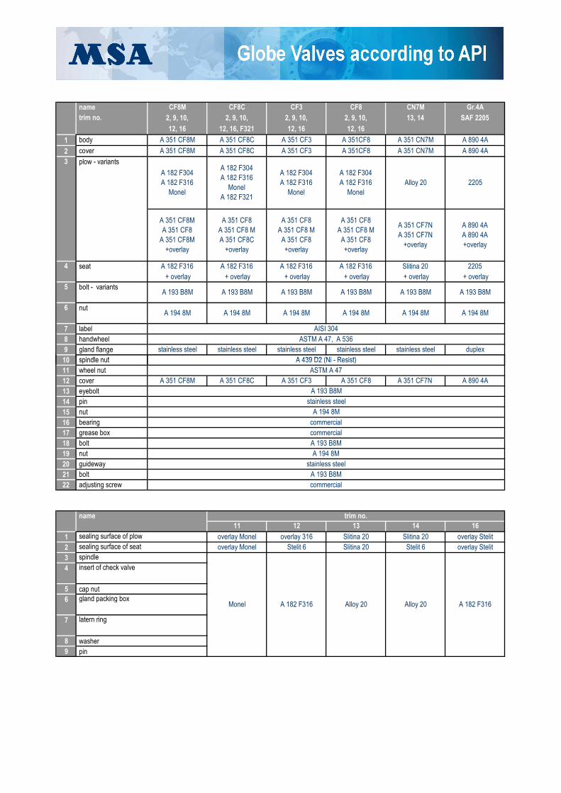
material design:
assembly:
testing:
order specification:
The globe valves can be assembled into the pipeline in a random position, but the installation into the position with avertical spindle axis is recommended.
The globe valves are subjected to pressure tests acccording to API 598 on strenght and tightness, tightness ofbackseat, closure tightness with low pressure ( if it is required in the order), closure tightness with high pressure.
The construction of cast steel globe valves of MSA is in accordance with the standard API 600, BS 18 73.A spindle has got an outer thread and is either rising rotative or rising non-rorative. The standard thread of spindle isANSI B 1.5, type ACME. The spindle and gland packing space meet the requirements of API 600. A spindle nut isplaced in the head of yoke cover firmly or on ball bearings. A cover joint is executed with the help of cover bolts andnuts.The globe valves has got cast (forged variably) plow that moves in the vertical direction to a sealing seat. The seatsare bolted or inserted and secured with a sealing weld around the flow circumference. The minimal thickness ofoverlay on the sealing surfaces of seat and plow is 1,6 mm, hardness depends on the type of overlay material. The operation is with a classical or impact handwheel or in combination with an angle gear box.The sealing of spindle si executed standardly with the plaited and pressed graphited rings. The properties of globevalve packings of MSA meet the requirements of the regulation Clean Air Act, Amendment from 1990.
The globe valves are supplied in the different material variants.
Designed dimensions of standard design are stated in the table below.
Data necessary for an order: type number, nominal diameter, pressure class, design (connection), type of operation,Data necessary for an order: type number, nominal diameter, pressure class, design (connection), type of operation,material of inner equipment, requested tests, accompanying documentation.

basic standard for construction
BS 18 73, API 600
ASME B 16.10
basic construction
designed dimension ASME B 16.10
ASME B 16.5
ASME B 16.25
API 598
ASME B 16.34
designed dimension
flange dimension
dimensions of welded ends
testing
dependence of maximal allowable pressure on temperature
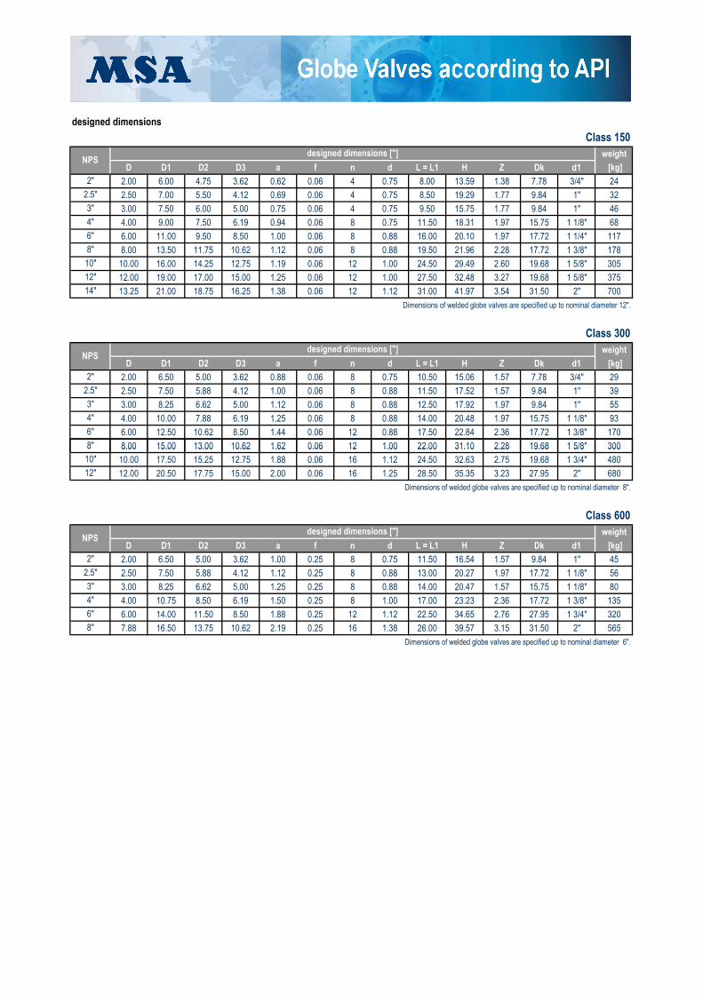
designed dimensions
Class 150
weight
D D1 D2 D3 a f n d L = L1 H Z Dk d1 [kg]
2.00 6.00 4.75 3.62 0.62 0.06 4 0.75 8.00 13.59 1.38 7.78 3/4" 24
2.50 7.00 5.50 4.12 0.69 0.06 4 0.75 8.50 19.29 1.77 9.84 1" 32
3.00 7.50 6.00 5.00 0.75 0.06 4 0.75 9.50 15.75 1.77 9.84 1" 46
4.00 9.00 7.50 6.19 0.94 0.06 8 0.75 11.50 18.31 1.97 15.75 1 1/8" 68
6.00 11.00 9.50 8.50 1.00 0.06 8 0.88 16.00 20.10 1.97 17.72 1 1/4" 117
8.00 13.50 11.75 10.62 1.12 0.06 8 0.88 19.50 21.96 2.28 17.72 1 3/8" 178
10.00 16.00 14.25 12.75 1.19 0.06 12 1.00 24.50 29.49 2.60 19.68 1 5/8" 305
12.00 19.00 17.00 15.00 1.25 0.06 12 1.00 27.50 32.48 3.27 19.68 1 5/8" 375
13.25 21.00 18.75 16.25 1.38 0.06 12 1.12 31.00 41.97 3.54 31.50 2" 700
Dimensions of welded globe valves are specified up to nominal diameter 12".
Class 300
weight
D D1 D2 D3 a f n d L = L1 H Z Dk d1 [kg]
2.00 6.50 5.00 3.62 0.88 0.06 8 0.75 10.50 15.06 1.57 7.78 3/4" 29
2.50 7.50 5.88 4.12 1.00 0.06 8 0.88 11.50 17.52 1.57 9.84 1" 39
3.00 8.25 6.62 5.00 1.12 0.06 8 0.88 12.50 17.92 1.97 9.84 1" 55
4.00 10.00 7.88 6.19 1.25 0.06 8 0.88 14.00 20.48 1.97 15.75 1 1/8" 93
6.00 12.50 10.62 8.50 1.44 0.06 12 0.88 17.50 22.84 2.36 17.72 1 3/8" 170
8.00 15.00 13.00 10.62 1.62 0.06 12 1.00 22.00 31.10 2.28 19.68 1 5/8" 300
8"
10"
12"
designed dimensions ["]
2.5"
3"
NPS
2"
designed dimensions ["]
8"
NPS
14"
2"
2.5"
3"
4"
6"
4"
6"
8.00 15.00 13.00 10.62 1.62 0.06 12 1.00 22.00 31.10 2.28 19.68 1 5/8" 300
10.00 17.50 15.25 12.75 1.88 0.06 16 1.12 24.50 32.63 2.75 19.68 1 3/4" 480
12.00 20.50 17.75 15.00 2.00 0.06 16 1.25 28.50 35.35 3.23 27.95 2" 680
Dimensions of welded globe valves are specified up to nominal diameter 8".
Class 600
weight
D D1 D2 D3 a f n d L = L1 H Z Dk d1 [kg]
2.00 6.50 5.00 3.62 1.00 0.25 8 0.75 11.50 16.54 1.57 9.84 1" 45
2.50 7.50 5.88 4.12 1.12 0.25 8 0.88 13.00 20.27 1.97 17.72 1 1/8" 56
3.00 8.25 6.62 5.00 1.25 0.25 8 0.88 14.00 20.47 1.57 15.75 1 1/8" 80
4.00 10.75 8.50 6.19 1.50 0.25 8 1.00 17.00 23.23 2.36 17.72 1 3/8" 135
6.00 14.00 11.50 8.50 1.88 0.25 12 1.12 22.50 34.65 2.76 27.95 1 3/4" 320
7.88 16.50 13.75 10.62 2.19 0.25 16 1.38 26.00 39.57 3.15 31.50 2" 565
Dimensions of welded globe valves are specified up to nominal diameter 6".
designed dimensions ["]
8"
10"
NPS
2.5"
12"
2"
3"
8"
4"
6"

standard material specification
1
2
7
8
9
10
body
seat
gland flange handwheel
A 350 LF2 A 106 B
+ overlayA 105
cover
+ overlay
A 216 WCB
A 182 F316
A 352 LCC
spindle nut
A 320 L7M
A 182 F9 + overlay
A 182 F316
A 351 CF8M
name
4
label
bolt - variants
6 nut
AISI 304
+ overlay + overlay
A 193 B7 A 193 B7
A 194 2H
A 439 D2 (Ni - Resist)
A 194 7M A 194 2HA 194 2H
A 194 7M A 194 2HA 194 2HM
+ overlay
A 320 L7M A 193 B7
+ overlayA 193 B7
A 193 B7M
+ overlay
A 105, [ČSN 41 1523]
+ overlay
ASTM A 47, A 536
A 352 LCC
A 182 F6a
A 352 LCB
12, 16
A 352 LCC + overlay
A 217 CA15
A 216 WCB
12
3 plow - variants
5
A 351 CF8M
+ overlay + overlay
A 350 LF2
trim no.
A 217 WC6 A 217 C5A 217 LCB
5
WC6WCB
1, 2, 5, 8, 9, 11
LCC C12
Monel
A 182 F9 A 217 C5
A 182 F316
A 182 F304A 216 WCB
C5LCB
A 217 LCB
5, 8
A 217 WC6 A 217 C5
A 217 C12 + overlay + overlay
A 217 C12A 217 C12
A 182 F6a
A 182 F5
A 217 WC6 + overlayA 351 CF8M
A 182 F321 A 182 F5
512
A 182 F9 + overlay
10
11
12
13
14
15
16
17
18
19
20
21
22
trim - material according to API 600
name
1 sealing surface of plow
2 sealing surface of seat
3 spindle
4 insert of check valve
5 cap nut6 packing box
7 latern ring
8 washer9 pin
sealing - material design
1 cover sealing 150, 300 600
2 gland packing 150, 300, 600(or according to customer´s requirements)
adjusting screw
wheel nut spindle nut
A 182 F6a A 182 F6a
A 182 F6aA 182 F6aA 217 CA15 A 217 CA15
A 217 CA15A 182 F6a
A 194 2H
2 5 8
commercial
A 182 F6aA 217 CA15A 182 F6a
overlay 13 CrStelit 6
A 276 410 T
A 182 F6a
A 182 F6a A 182 F6a A 182 F6aA 182 F6a
overlay 13 Cr
A 182 F6aA 182 F6a
A 182 F304
A 182 F6a CI.4
A 182 F6a A 182 F6a
A 182 F6a
A 217 CA15 A 217 CA15
A 276 410 TA 182 F6a CI.4
9
overlay 13 Cr
1
eyebolt
bearing
A 193 B7 bolt
bolt grease box
nut pin
Stelit 6
cover
overlay 304
A 276 410 T
A 182 F6a
A 216 WCB
A 182 F6a
A 217 CA15
nut A 194 2H
A 182 F6a
commercial
A 182 F6a CI.4A 276 410 T
overlay Stelit
A 217 CA15
A 193 B7
guideway
overlay Moneloverlay Monel
A 439 D2 (Ni - Resist)
commercial
A 217 CA15
carbon steel
A 217 CA15
carbon steel
Stelit 6
set of graphited cords and graphited rings
A 193 B7, A 307 Gr B
ASTM A 47
type of sealing
A 217 CA15
name
A 217 CA15
RTJ rings spiral graphited sealing
trim no.
Class
A 182 F6a CI.4
(or according to customer´s requirements)
1
2
7
8
9
10
cover
12, 16
2, 9, 10,
name
trim no.
12, 16, F321
body
+ overlay
12, 16
A 351CF8
CF8M CF8
A 351 CF8M
A 193 B8M
A 351CF8 A 351 CN7M
A 182 F316 + overlay
A 182 F316
A 193 B8M
12, 16
CF3
A 193 B8M
+ overlay
SAF 2205
A 351 CF3
Alloy 20
13, 14
A 890 4A
2, 9, 10, 2, 9, 10,
A 194 8M A 194 8M
CN7M Gr.4A
A 351 CN7M A 890 4A
3 plow - variants
4 seat
A 351 CF8M
5
6 nut
label
A 351 CF8C
A 439 D2 (Ni - Resist) spindle nut
A 182 F304 A 182 F316
Monel A 182 F321
A 351 CF8M A 351 CF8
A 351 CF8M +overlay
A 351 CF8 A 351 CF8 M A 351 CF8C
+overlay
A 351 CF8 A 351 CF8 M
A 351 CF8 +overlay
bolt - variants
handwheel
A 194 8MA 194 8M
A 351 CF8 A 351 CF8 M
A 351 CF8 +overlay
CF8C
2205
A 194 8MA 194 8M
gland flange
A 193 B8M
A 182 F316 A 182 F316 Slitina 20 2205
A 193 B8M
+ overlay
A 182 F304 A 182 F316
Monel
A 351 CF8C
stainless steel stainless steel duplexstainless steel stainless steel stainless steel
2, 9, 10,
A 351 CF3
AISI 304ASTM A 47, A 536
A 193 B8M
+ overlay + overlay
A 351 CF7N A 351 CF7N
+overlay
A 890 4A A 890 4A +overlay
A 182 F304 A 182 F316
Monel
A 182 F304 A 182 F316
Monel
10
11
12
13
14
15
16
17
18
19
20
21
22
name
1 sealing surface of plow
2 sealing surface of seat
3 spindle
4 insert of check valve
5 cap nut6 gland packing box
7 latern ring
8 washer9 pin
overlay Monel overlay 316 Slitina 20
1612
A 890 4A
commercial
A 351 CF8M
A 182 F316
trim no.
14
Monel
overlay Stelitoverlay Stelit
overlay Monel
nut
pin
A 182 F316 Alloy 20 Alloy 20
13
Stelit 6Slitina 20Slitina 20
Stelit 6
11
adjusting screw
A 439 D2 (Ni - Resist)
A 351 CF8C A 351 CF3 A 351 CF8 A 351 CF7N
guideway
bearing grease box
spindle nut
bolt
wheel nut
nut
cover
boltcommercialcommercial
stainless steel eyebolt
A 193 B8M
ASTM A 47
stainless steelA 193 B8M
A 194 8M
A 194 8M
A 193 B8M

applied standards:
B 16.5 flange, pipeline and valve B 16.10 designed dimensions B 16.25 welding ends B 16.34 valves - flanged, bolted and welded B 1.20.1 screw threads, general purpose B 16.47 larger steel flanged dimensions (substitute for API 605 and MSS SP-44) B 31.1 pipeline for chemical factories and refineries
ASTM material specification ASME instrucions for vessels under pressure API specification for quality systems
specification for pipeline valvesbolted cover of steel gate valve for oil and gas industriesvalve inspections and testingfire-resistant sealing and sealing materialstandards for pipelines
MSS standard ends of contact surfaces for pipeline and valve flangesstandard markings for valves, flanges and connecting componentsflanges fo steel pipelinesmethod of magnetic testingmethod of radiographic testingvisual inspection of steel castingsgraphited sealing for valves with rising spindle (constructional requirements)
Std 589
SP-54
SP-55
SP-120
SPEC 5L
SP-6
SP-25
SP-44
SP-53
SPEC 6D
600
Std 598
SPEC Q1
part V,VIII, IX
ASME
graphited sealing for valves with rising spindle (constructional requirements)
NACE ISO 15156 - materials for H2S - for oil and gas industrymaterials resistant to cracking in the corrosive oil surrounding
British standards:
BS 1414 steel gate valve - flanged or welding ends for petrochemistry 1868 steel swing check valves - flanged or welding ends for petrochemistry 1873 steel globe valves and flanged swing check valves for petrochemistry 1560 round pipe flange, flanges and valves 2080 designed dimensions 5146 valve inspections and testing
international standards:
EN ISO 9001
ISO 5211 designed dimensions of actuators to valves EN 10 204 type of document for inspection ISO 10 434 / API 600 bolted cover of steel gate valves for petrochemistry ISO 14�313 / API 6D petrochemistry - transfer pipeline system - pipeline valves ISO 5208 industrial valves - valve testing with pressure
MR-01-75
MR-01-03
quality system
SP-120

quality system:
testing:
MSA, a.s. executes the whole range of special tests which verify the properties of valves. They are as follow:
pressure testing
fire testing
testing on seal strenghtTest of seal strenght is executed with methan.
cycle testingCycle test is executed by 3000 cycles (open-close) with water.
hydrodynamic and aerodynamic testingMSA, a.s executes this test for the verification of hydropneumatic and aerodynamic properties.
operating testingOperating test is executed on all valves at MSA, a.s.
The whole manufacturing process is completely monitored and includes the following tests and inspections: acceptanceinspections of all input materials and sub-deliveries, inspections of particular components in the course of manufacture, assemblytesting, pressure testing, operating testing, non-destructive testing and final inspections of finished product.
Fire test is executed at MSA, a.s. according to the standard API 6FD, API 607 and BS 6755, part 2, for pressure class 150, 300 and 600.
All pressure tests are executed according to API 598, API 600, API 6D and DIN 3230. MSA, a.s. also performs standardlythe special tests according to API 6D. A criterium for acceptance is zero permeability. At the same time, MSA, a.s. executesstandardly testing at full operating pressure by which a possible leakage could be detected in the body-cover joint, spindle,fittings or grease box etc.
Operating test is executed on all valves at MSA, a.s.non-destructive testing
visual inspection
certification:
Quality system of MSA, a.s. is certified according to EN ISO 9001:2000 and API Spec Q1 (Specification D - number 0239).
research and development:
Specialists of MSA, a.s. work on the development and research of new products and verify their properties as well such as: - suitability of applied material - strenght and rigidity of construction (FEM method) - operability with the emphasis on strenght and controlability - hydraulic and aerodynamic properties etc.
New products are tested in the testing room of MSA, a.s. as well as in real operating conditions. The properties of product areobserved during the whole service life and findings are applied in the development and production of new products.
MSA, a.s. executes the non-destructive test in the own facilities and testing room. The non-destructive test includes RT, MT,UT or DP testing. The testing operators are higly qualified and certified according to EN 473 or STN-TC-1A.
Visual inspection is performed at all castings that are used for the valves of MSA, a.s. according to the quality directive MSSSP-55 for steel castings and according to order specifications.