the gluteal region - university of kwazulu-natal
TRANSCRIPT

Pluggable Optics- Featuring 40G &
100G and other advancements
PTT Forum
Dec 2013
© 2013 Finisar Corporation

Data Center Architectures are Changing
Access Layer
Aggregation
Layer
Core Layer
Data Centers becoming larger, more modular, more homogenous
Workloads spread across 10s, 100s, sometimes 1000s VMs and hosts
Network migrating from traditional 3-tier to flattened 2-tier topology
Higher degree of east-west traffic across network
Traditional ‘3-tier’ Tree Network New ‘2-tier’ Leaf-Spine Network
East-West
No
rth
-So
uth
© 2013 Finisar Corporation 2
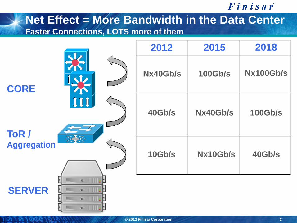
Net Effect = More Bandwidth in the Data Center Faster Connections, LOTS more of them
CORE
ToR / Aggregation
SERVER
2012 2015 2018
10Gb/s
40Gb/s
Nx40Gb/s
Nx10Gb/s
Nx40Gb/s
100Gb/s
40Gb/s
100Gb/s
Nx100Gb/s
3 © 2013 Finisar Corporation

Interconnect, Peering & Transport Changing
Peering and Interconnects moving from 1G & 10G to 100G
Router-Router and Router-Transport client interfaces
Critical requirements are time to market and supporting multiple reaches
High port density is usually a secondary consideration for now
Currently deploying thousands of 100GE CFP (LR4, SR10, some ER4)
Next-generation systems will use 100GE CFP2 (LR4, SR10, SR4, ER4)
CXP (modules and AOC) is being used for inter-chassis connections (short MMF links)

© 2013 Finisar Corporation Confidential 5
40G vs. 100G in the Data Center
100G has:
Highest density
Lowest power consumption/bit
MMF reaches up to 100m
40G has:
Lowest cost/bit
MMF reaches up to 300m
SMF and MMF in a common
form factor (QSFP+)
Source: Lightcounting Ethernet Forecast, Dec. 2012
Multimode Fiber Single Mode Fiber
40G is here to stay

40G at a Glance
• 40GBASE-SR4 and 4 x 10GBASE-SR
• 4 lanes x 10.3 Gb/s
• XLPPI electrical interface
• Link distances up to 100m on OM3 (150m on OM4)
• Link distances up to 300m on OM3 (400m on OM4)
• 40GBASE-LR4
• 40G CWDM QSFP transceiver module
• MSA-compliant QSFP+ form factor and XLPPI
interface
• Maximum link length of 10km on Single Mode Fiber
(SMF)
• 40G AOC Quadwire
• QSFP-based active optical cable
• 4 lanes: 1 - 10.5G
• Standard lengths from 1 to 100m
• Multiple Cable types

QSFP: 40G and High-Density 10G
QSFP+ QSFP+
SFP+
SFP+
SFP+
SFP+
4x10G Breakout
QSFP+ QSFP+ QSFP+ QSFP+
Point-to-Point 40G QSFP+ QSFP+
QSFP+ QSFP+
QSFP+ QSFP+
QSFP+ QSFP+
QSFP+ QSFP+
QSFP+ QSFP+
QSFP+ QSFP+
QSFP+ QSFP+
4x10G Shuffle
QSFP+ = Quad SFP+
This is both a 40G and a high-density 10G form factor
QSFP+ QSFP+ QSFP+ QSFP+
SFP+
SFP+
SFP+
SFP+ QSFP+ QSFP+
QSFP+ QSFP+
SFP+
SFP+
SFP+
SFP+
General Case:
Breakout and Shuffle
QSFP is a very high runner,
because it addresses both
40G and 10G links.

100G Ethernet Standardization
IEEE 802.3ba
100GBASE-LR4 10km SMF Based on 4x25G LAN-WDM
100GBASE-ER4 40km SMF Based on 4x25G LAN-WDM
100GBASE-SR10 100m OM3 MMF(*) Based on 10x10G Parallel MMF
CAUI 10x10G retimed electrical I/O
CPPI 10x10G un-retimed electrical I/O
Note that “10x10G SMF” (i.e., Neophotonics/Santur’s so-called “LR10”) is not a standardized
IEEE interface!
IEEE 802.3bm (in process)
100GBASE-SR4 ~100m OM3 MMF Based on 4x25G Parallel MMF
CAUI-4 4x25G retimed electrical I/O
(*) 150m on OM4 MMF

100G Ethernet Snapshot
100GE is already here Many thousands of 100GE links are already deployed in the field
The vast majority are CFP modules
100GE OEMs is rapidly expanding New IEEE optical/electrical standards (SR4, CAUI-4, 500m)
New higher density 100GE module form factors: CFP2, CFP4, QSFP28
Designs for high port-count 100GE systems have started
Many 100GE products will also be used for high-density 10GE applications in high volume
The 100GE and Nx10G markets
is expected to grow substantially
in the next three years (37% CAGR)
$140
$194
$245
$361
CY12 CY13 CY14 CY15
100GE Transceiver Market (in $K)
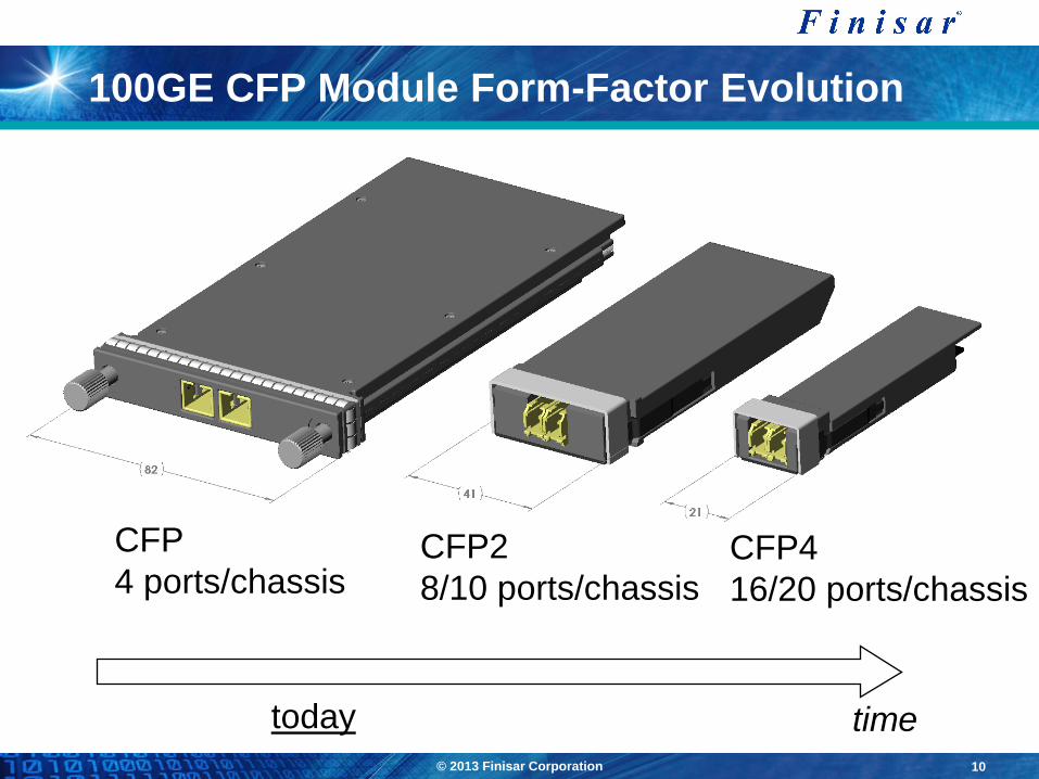
100GE CFP Module Form-Factor Evolution
time
CFP
4 ports/chassis CFP2
8/10 ports/chassis CFP4
16/20 ports/chassis
today
© 2013 Finisar Corporation 10
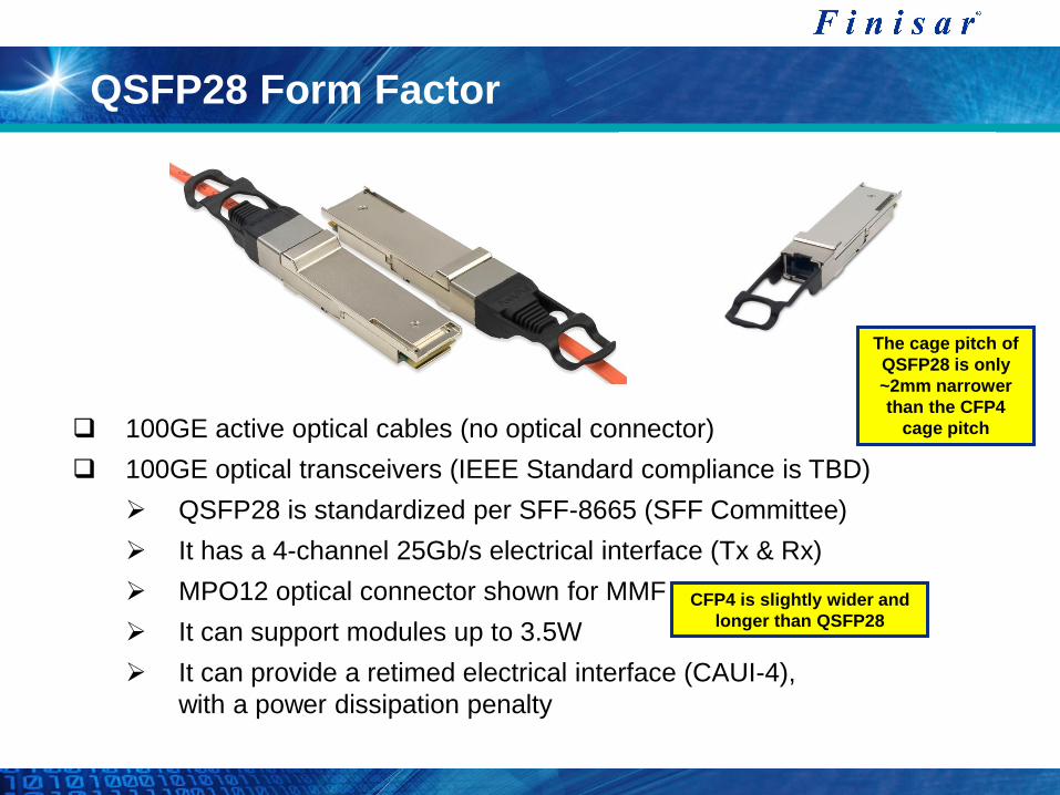
QSFP28 Form Factor
100GE active optical cables (no optical connector)
100GE optical transceivers (IEEE Standard compliance is TBD)
QSFP28 is standardized per SFF-8665 (SFF Committee)
It has a 4-channel 25Gb/s electrical interface (Tx & Rx)
MPO12 optical connector shown for MMF
It can support modules up to 3.5W
It can provide a retimed electrical interface (CAUI-4),
with a power dissipation penalty
The cage pitch of
QSFP28 is only
~2mm narrower
than the CFP4
cage pitch
CFP4 is slightly wider and
longer than QSFP28

100G Module Port Densities
4x CFP
10x CFP2
18x CFP4
36x CFP4
Belly-to-belly
20x QSFP28
40x QSFP28
Stacked
CFP2
enables
1Tb/s per
blade
432 mm

100G Form Factor Applications in the Market
Telecom Carrier Environment: Router-Router and Router-Transport client interfaces
Critical requirements are time to market and supporting multiple reaches
High port density is usually a secondary consideration for now
Currently deploying thousands of 100GE CFP (LR4, SR10, some ER4)
Next-generation systems will use 100GE CFP2 (LR4, SR10, SR4, ER4)
CXP (modules and AOC) is being used for inter-chassis connections (short MMF links)
Data Center and Enterprise Switches: 100GE uplinks and 10GE fan-outs
The critical requirement is high port density
Currently deploying mainly 10GE SFP+, 40GE QSFP+ and some 40GE CFP
First 100GE systems will deploy 100GE CFP2 (LR4, SR10, SR4, ER4)
CXP will only be used when SMF support is not required by the system
Next generation systems will deploy 100GE CFP4 and 100GE QSFP28
CXP, CFP2 and CFP4 form factors will also be used for 10GE fan-out
applications (enabling higher 10GE port densities than SFP+)

© 2013 Finisar Corporation
Active Optical Cables Primer
Compared to Optical Transceivers
Cost-optimized: Not constrained by optical interface specifications driven by longer-reach applications
Datacenter/Consumer friendly: No cleanliness issues in optical connector
Disadvantage: Cannot be routed through optical patch panels
Pin RX
VCSEL Laser
Driver
Post-
Amp Pin RX
VCSEL Laser
Driver
Post-
Amp
Electrical Electrical
Compared to Copper Cables
Longer reach
Lower weight and tighter bend
radius, means easier cable
management
Thinner cables allow better
airflow for cooling
Lower power consumption,
with no power-hungry
conditioning ICs required on the
host board
Optical-to-Electrical conversion is inside the cable end-plugs
Optical
14

Long span/Inter-building
10G SFP+ LR 10km SMF
40G QSFP+ LR4 10km SMF
100G CFP DWDM
SMF, Low-latency
Optics For the Data Center
Ethernet Networking Applications
Intra-rack
10G Laserwire®
10G SFP+ SR
Inter-rack
10G SFP+ SR 300m OM3 MMF
400m OM4 MMF
10G Laserwire®
Up to 30m
40G QSFP+ SR4 100m OM3 MMF
150m OM4 MMF
40G Quadwire®
Up to 300m
100G CXP SR10 100m OM3 MMF
150m OM4 MMF
100G C.wire® Up to 300m
© 2013 Finisar Corporation 15

Optics for Router/WAN Links
10G Interfaces
SFP+ LR 10km SMF
SFP+ ER 40km SMF
SFP+ ZR/DWDM 80km SMF
XFP ER/ZR/DWDM 80km SMF
40G Interfaces
40G CFP SR4 100m OM3 MMF
150m OM4 MMF
40G CFP LR4 10km SMF
100G Interfaces
100G CFP SR10 100m OM3 MMF
150m OM4 MMF
100G CFP LR4 10km SMF
100G CFP DWDM ~500km SMF
© 2013 Finisar Corporation 16

Recap
Content and Application growth is driving:
Growth in traffic
Growth in optics
40G and 100G optics developments are supporting the growth in traffic
with:
Smaller form factors
Lower power consumption per bit
Lower cost per bit
Perguntas?
Muito Obrigado!