the great chilled water debate - cibse
TRANSCRIPT

THE GREAT CHILLED WATER DEBATE
Michael Dagher
Central Chiller Plant• Direct-Primary, Variable Flow?
• Variable Primary / Variable Secondary (Decoupled)?
• Parallel Vs Series Counterflow?
• Pressure Control?
• What is right/wrong?
Chilled Water Pumping Schemes
Load Load Load
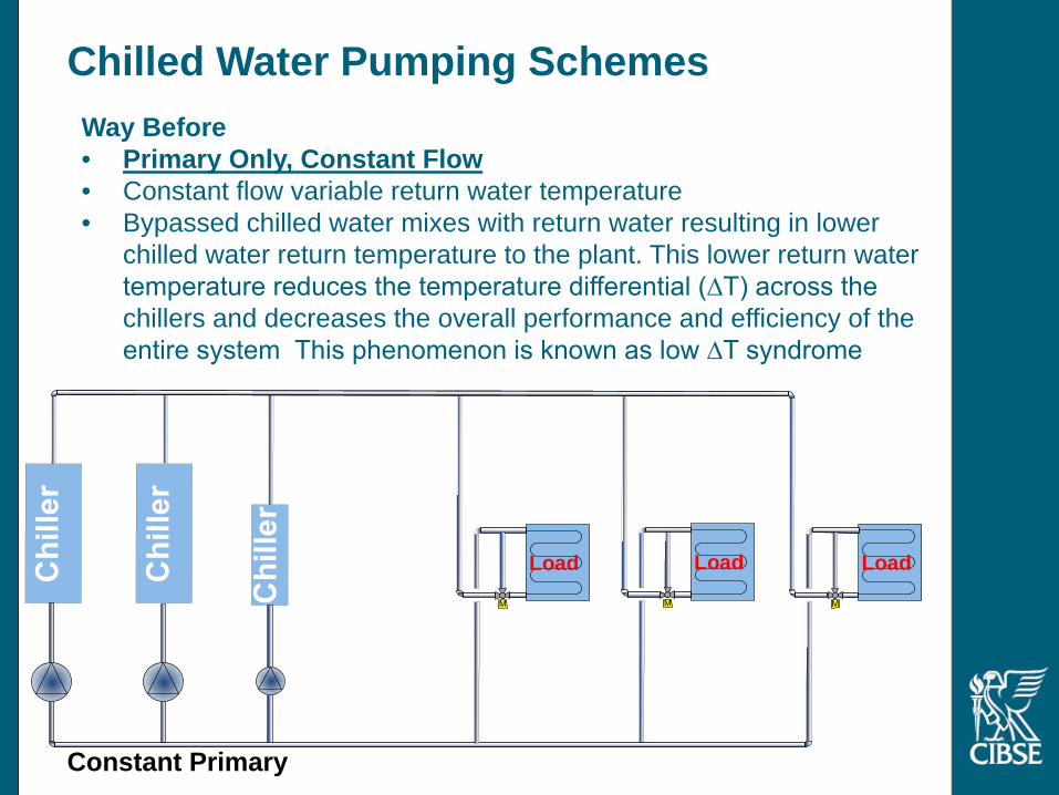
Way Before• Primary Only, Constant Flow• Constant flow variable return water temperature• Bypassed chilled water mixes with return water resulting in lower
chilled water return temperature to the plant. This lower return water temperature reduces the temperature differential (∆T) across the chillers and decreases the overall performance and efficiency of the entire system This phenomenon is known as low ∆T syndrome
Constant Primary

Load Load Load
Variable SecondaryConstant Primary
Chilled Water Pumping SchemesLittle Later in 1950s• Decoupled Constant Primary, Variable Secondary• Maintained use of 3-way valves• Decoupler pipe located in plantroom• +ve or –ve flow possible through decoupler• The low ∆T syndrome reduced but still a problem
+ve
-ve

Load Load Load
M
Variable SecondaryConstant Primary
M
Staged
Chilled Water Pumping SchemesThen in Late 1980s• Decoupled Constant Primary, Variable Secondary• Two way control valves introduced• Secondary pumps staged to match coil water flow demands• Some three-way control valves are used together with two-way valves
to provide a means of maintaining a minimum secondary pump flow• The low ∆T syndrome further reduced but still a problem
+ve
-ve

Load Load Load
MM
M
Chilled Water Pumping SchemesEarly 1990s• Primary Only, Constant Flow• Constant flow variable return water temperature• Smaller less complex distribution with Bypass in plantroom with field
predominantly 2 way control valves at coils. Constant flow in plantroom, variable flow in field. The configuration also suffers from the low ∆T syndrome.
Constant Primary

Load Load Load
M
Variable SecondaryVariable Primary
M
Variable Speed Pumps
VSD VSD VSD
FM
-Ve
+Ve
Chilled Water Pumping SchemesSince late 1990s• Decoupled Variable Primary, Variable Secondary• Chiller manufacturers allow designers to vary flow through the chillers,
provided evaporator tube velocities and rate of change of flow through the evaporator are managed.
• With the introduction of variable primary flow, it was now possible to match the primary and secondary flows and the decoupler flow was minimised, addressing the low ∆T syndrome for majority of the time.
Load Load Load
MM
Variable Primary Only
M
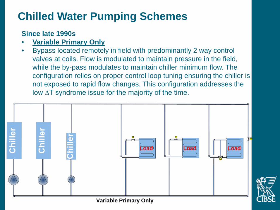
Chilled Water Pumping SchemesSince late 1990s• Variable Primary Only• Bypass located remotely in field with predominantly 2 way control
valves at coils. Flow is modulated to maintain pressure in the field, while the by-pass modulates to maintain chiller minimum flow. The configuration relies on proper control loop tuning ensuring the chiller is not exposed to rapid flow changes. This configuration addresses the low ∆T syndrome issue for the majority of the time.

Load Load Load
MM
Variable Primary OnlySeries Counterflow Chiller Arrangement
M
Chiller ArrangementNow• Variable Primary Only, Series Counterflow • This configuration improves overall chiller efficiency by reducing the
lift on the compressor. Pumping energy can be higher than parallel arrangement. Pump selection crucial and avoid oversizing (as they need to modulate flow between 100 down to 40%)

Chilled Water Distribution Schemes
M
Variable Primary + Booster
LoadM
LoadM
LoadM
LoadM
LoadM
Bui
ldin
g A
LoadM
LoadM
LoadM
LoadM
LoadM
Bui
ldin
g B
LoadM
LoadM
LoadM
LoadM
LoadM
Bui
ldin
g C
VSD
M
VSD VSD VSD
Pressure Sensors & By-
Pass
Pressure Sensors & By-
Pass
Booster Pump
Variable Secondary
Variable Primary
LoadM
LoadM
LoadM
LoadM
LoadM
Bui
ldin
g A
VSD
M
Pressure Sensors & By-Pass
LoadM
LoadM
LoadM
LoadM
LoadM
Bui
ldin
g B
VSD
M
Pressure Sensors & By-Pass
LoadM
LoadM
LoadM
LoadM
LoadM
Bui
ldin
g C
VSD
M
Pressure Sensors & By-Pass
VSD VSD VSD
FM
Decoupler
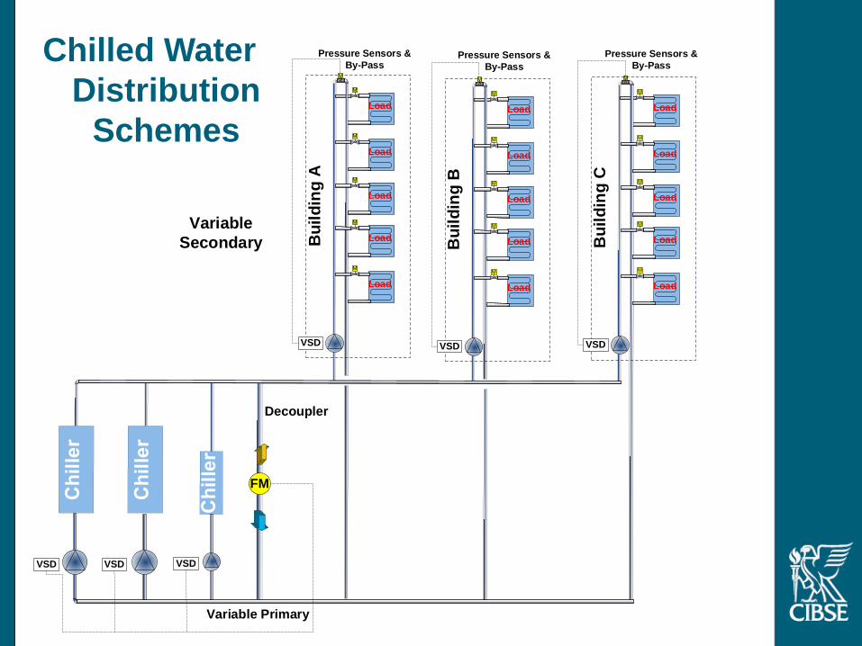
Chilled Water Distribution
Schemes

Advantages & Disadvantages of Decoupled Primary/Secondary
Advantages•Simple to apply to large complex precinct systems•Stable Flow through Chillers
Disadvantages•Costly (≈ 5% higher than Primary Only)•Greater pumping energy (≈ 5% higher overall plant energy than Primary Only)

Load Load Load
MM
Variable Primary Only
Pres
sure
Dro
p
Node
A
B
C
D
EF G H I
JKLM
AB
C D
N
E FG
HI
J
KL
MN
VSD VSD VSD
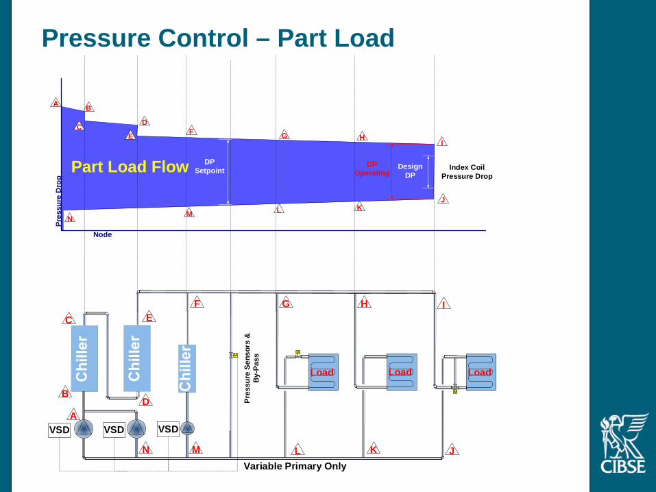
Index Coil Pressure Drop
DP Setpoint
Pressure Sensors & By-
Pass
M
Pressure Control – Design Load
100% Design Flow

Load Load Load
MM
Variable Primary Only
Pres
sure
Dro
p
Node
A
B
C
D
EF G H I
JKLM
A B
C D
N
E F G H I
JKLMN
VSD VSD VSD
Index Coil Pressure Drop
DP Setpoint
Pressure Sensors & By-
Pass
M
Pressure Control – Part Load
Part Load Flow
Load Load Load
MM
Variable Primary Only
Pres
sure
Dro
p
Node
A
B
C
D
EF G H I
JKLM
A B
C D
N
E F G HI
JKLMN
VSD VSD VSD
Index Coil Pressure Drop
DP Setpoint Design
DPDP
Operating
Pres
sure
Sen
sors
&
By-P
ass
Pressure Control – Part Load
Part Load Flow

What is right or wrong?• Depends on the particular application
• Look at all options don’t jump to conclusion too soon
• Its about the system nothing but the whole system
• Optimise each element, chillers, pumping, flow/pressure control, cooling tower fan energy
• Staging strategy
• Temperature controlled
• Reset T and DP
• Avoid the temptation of oversizing, can hurt you at part load (+70% of time). Don’t optimise the plant for that one hour of the year.
• Work with the chiller manufacturer don’t do it alone

THE GREAT CHILLED WATER DEBATE
Stefan Sadokierski

Primary – Secondary Arrangement• Primary circuit:
• Fixed or variable flow, • Pump controlled to bypass flow or system thermal load
• Secondary circuit – variable flow controlled to pressure• Positives
• Primary / secondary hydraulically decoupled, • Simple, robust, well understood, easy to operate
• Issues• Excess pumping• Mixing of excess primary and secondary return

Primary Only Arrangement• Single pump set controlled to pressure• Bypass only opens below lowest turndown of smallest chiller
• dP (as shown)• Flow
• Positives – cost, plant space, efficiency• Issues
• Complex controls• Loss of LWT set point on staging• Different chiller sizes means dissimilar pumps in parallel

Primary Only – Pros and Cons• PROS
• Lower first cost• Less plant space• Improved efficiency (typically 3-8%)• Fewer components (possibly improved reliability)
• CONS• Likely loss of LWT set point when staging on / off • Increased controls complexity • Best performance with chillers all same capacity• Additional commissioning
• RECOMMENDATION• Significant potential benefits – should be considered• Application – not recommended if stable LWT is needed for
critical cooling or dehumidification processes• End User – must be informed and trained

Series Counter-Flow Arrangement• Variable primary arrangement• Chiller pairs in series• Counterflow – condenser water flows in opposite direction (not shown)• Compressor lift minimised

Series Counter-Flow – Pros and Cons• PROS
• Improved compressor efficiency (~5% for 3+3 = 6°C dT CHW)• Transient chilled water flow issues on staging mitigated
• CONS• Increased pumping power (out weighted by compressor savings)• Increased “N” chiller capacity – impact on redundancy• Increased controls complexity
• RECOMMENDATIONS• Standard approach for district cooling applications:
• Well suited to high dT applications (dT > 7°C) – maintain compressor efficiency and reduce distribution costs
• Well suited to large load applications – larger N capacity ok• Can be applied elsewhere, more suited to larger loads• Consider planned and unplanned maintenance activities

Other ways to make similar savings
• Compressor power ~ refrigerant mass flow x lift…• Increase evaporating temperature• Reduce condensing temperature
• Chilled water leaving temperature• Often at 6/12 or 7/14 °C• 10 / 17 °C common practice in UK (won’t work for LT VAV)
• Condenser water temperature• Typically WB approach of 5.5 (24 °C wb + 5.5 = 29.5 °C LWT)• Larger tower can be reduced to 2.5 (26.5 °C LWT)
• Compare extremes:• CHW at 6/12 and CDW at 29.5 = 23.5 °C lift• CHW at 10/17 and CDW at 26.5 = 16.5 C lift
• Optimised control of CDW temperature to minimise compressor and fan power (ASHRAE sequencing strategy)

THE GREAT CHILLED WATER DEBATE
Barry Abboud

Overview
• The three basic piping systems• Low DeltaT Syndrome – causes, effects, and
solutions• Design & Control Considerations (VPF)• Series Counter Flow

Chilled Water Piping System Types (typical)
ConfigurationLoad
Valves Installed Cost Pumping Cost
Constant Primary Flow 3-way Lowest Highest
Primary / Secondary 2-way Highest Medium
Variable Primary Flow 2-way Medium Lowest

Secondary Pumps
= Flow X DeltaTLoad
4
Constant Primary FlowWith Dedicated Pumping

Secondary Pumps
47 ºF(8.3 ºC)
47 ºF(8.3 ºC)
47 ºF(8.3ºC)
(63 l/s) 56 ºF(13.3 ºC)
(1760 kW)
47 ºF(8.3 ºC)
25%
(189 l/s) @ 8.3 ºC)47 ºF
(189 l/s) @ 6.7 ºC)
5
Primary
Flow 3000gpm (189 l/s)
Delta T 3oF (1.7oC)
Per Chiller System
Load 125 Tons (440kW) 375Tons (1320kW)Constant Primary FlowWith Dedicated Pumping

AdvantagesLowest installed costLess plant space than P/SEasy to Control & OperateEasy to Commission
DisadvantagesHighest Plant Energy Cost (must run all,
even at low loads)
6
Constant Primary Flow

Secondary Pumps
= Flow X DeltaTPLoad
7
= Flow X DeltaTSLoad
Primary (const.) / Secondary (Variable)

PRIMARY (VARIABLE) / SECONDARY (VARIABLE)HEADERED PUMPING
Secondary Pumps
8

PRIMARY/SECONDARY AT 25% LOAD
(63 l/s)
(1760 kW)
Secondary Pumps750 GPM @ 44 ºF
47 l/s @ 6.7 ºC
53 ºF(11.7 ºC)
56 ºF(13.3 ºC)
Per Chiller System
Load 375 Tons (1320kW) 375 Tons (1320kW)
Primary Secondary Bypass
Flow 1000gpm (126 l/s) 750gpm (47 l/s) 250gpm (16 l/s)
Delta T 9oF (5oC) 12oF (6.7oC) ----
250 GPM @ 44 ºF16 l/s @ 6.7 ºC
25%
750 GPM @ 56 ºF(47l/s) @ 13.3 ºC)
1000 GPM @ 53 ºF(63 l/s) @ 11.7 ºC)
44.0 °F(6.7 °C)
9
25% Load = 25% Sec Flow

PR
ES
SU
RE
DIFFE
RE
NT
IAL
SE
NS
ORC
ON
TR
OLS
SE
CO
ND
AR
YP
UM
PS
PE
ED
Differential Pressure sensor down stream controls speed to Set Point (coil WPD+Valve PD+Piping PD+Safety) located at end of Index Circuit for best efficiency
Set PointP=25 ft (76 kPa)
P
10

= Flow X DeltaTLoad
Variable Primary Flowat 100% System Load
Two-way valves control capacityBy varying flow of water in coils
Primary PumpsChillers Closed
11
Variable Primary Flow

Variable Primary Flowat 25% System Load
Two-way valves control capacityBy varying flow of water in coils
Per Chiller System
Load 375 Tons (1320kW) 375 Tons (1320 kW)
Primary Bypass
Flow 750 gpm (95 l/s) 0 gpm (0 l/s)
Delta T 12oF (6.7oC) ----
56 ºF(13.3 ºC)
0 GPM @ 44 ºF0 l/s @ 6.7 ºC
750 GPM @ 56 ºF(47 l/s) @ 13.3 ºC)
44.0 °F(6.7 °C)
750 GPM @ 56 ºF(47 l/s) @ 13.3 ºC)
Primary Pumps750 GPM
(47 l/s)
750 GPM @ 44 ºF47 l/s @ 6.7 ºC
56 ºF(13.3 ºC)
Closed
12
25% Load = 25% Flow
Variable Primary Flow at 25% Load

13
VA
RY
ING
FLO
WT
HR
OU
GH
CH
ILLER
S-IS
SU
ES
Issue During Normal Operation
Chiller Type (centrifugal fast, absorbers slow)
Chiller Load (min load - no variance, full load - max variance)
System Water Volume (more water, more thermal capacitance, faster variance allowed)
Active Loads (near or far from plant)
Typical VSD pump ramp rate setting of 10%/minute (guide for stable temp control)
Issue Adding Chillers
Modulating isolation valves on chillers
13
Issues with Varying Flow through Chillers

Advantages Lower Installed Cost (approx. 5% compared P/S)
No secondary Pumps or piping, valves, electrical, installation, etc.Offset somewhat by added 2W Bypass Valve and more complex
controls Less Plant Space Needed Best Chilled Water Pump Energy Consumption (most optimised
configuration) VSD energy savings Lower Pump Design Head Higher Pump Efficiency Lower potential impact from Low Delta T (can over pump chillers if
needed)
Variable Primary Flow (VPF) System Arrangement
14

PUMP CURVES - PUMP EFFICIENCY
With VPF you will need larger pumps compared to P/S, but they will be operating at a more efficient point, yielding energy savings
15

DisadvantagesRequires more robust (complex and properly calibrated) control
systemRequires coordinated control of chillers, isolation valves, and
pumpsPotentially longer commissioning times to tune the systemNeed experienced facility manager to operate/maintain properly
Variable Primary Flow (VPF) System Arrangement
16

MAJOR CAUSES OF LOW DELTA T
Dirty Coils
Controls Calibration
Leaky 2-Way Valves
Coils Piped-Up Backwards
Mixing 2-Way with 3-Way Valves in the same system
17

NEGATIVE EFFECTS OF LOW DELTA T IN P/S SYSTEMS
Consequences: Higher secondary pump energy
pumps run faster
Higher chilled water plant energy Ancillary equipment
Can’t load up chillersmore than ratio Act DT / Des DT 10/12 = 83%
18

NEGATIVE EFFECTS OF LOW DELTA T IN VPF SYSTEMS
19
Consequences: Higher secondary pump energy
pumps run faster
Higher chilled water plant energy Ancillary equipment
Can’t load up chillersmore than ratio Act DT / Des DT 10/12 = 83% or 417 tons

SOLUTION TO (OR REDUCE EFFECTS OF) LOW DELTA T
Address the causes Clean Coils Calibrate controls periodically Select proper 2W valves (dynamic/close-off ratings) and maintain them No 3W valves in design Find and correct piping installation errors
Over deltaT chillers by resetting supply water down (P/S) Over pump chillers at ratio of Design Delta T / Actual Delta T (VPF) Use VSD Chillers & Energy-based sequencing (from 30 to 80% Load)
Solve at Load, Mitigate at Plant
20

21
VPF SYSTEMS DESIGN/CONTROL CONSIDERATIONS
Chillers Equal Sized Chillers preferred, but not required Maintain Min flow rates with Bypass control (manufacturer) Maintain Max flow rates (3 m/s) and max WPDs (manufacturer) Modulating Isolation Valves (or 2-position stroke-able) set to open in 1.5 to 2 min Don’t vary flow too quickly through chillers (VSD pump Ramp rate – typical setting of 10%/min) Sequence
If CSD Chillers – Load-based sequencing…run chillers to max load (Supply Temp rise). Do not run more chillers than needed (water-cooled, single compressor assumed)
If VSD Chillers – Energy-based sequencing…run chillers between 30% and 80% load (depending on ECWT and actual off-design performance curves). Run more chillers than load requires.
Add Chiller - CHW Supply Temp or Load (Flow X Delta T) or amps (if CSD) Subtract Chiller - Load (Flow X Delta T) or Amps (if CSD)
21

VPF SYSTEMS DESIGN/CONTROL CONSIDERATIONS
Pumps Variable Speed Driven Headered arrangement preferred Sequence
with chillers (but run an extra pump than # chillers for over-pumping in low delta T situations) Flow-based sequencing Energy-based sequencing (most efficient combination of pumps)
Speed controlled by pressure sensors at end of index circuit (fast response important) Direct wired Piggyback control for large distances Optimized - Reset pressure sensor by valve position of coils
22

VPF SYSTEMS DESIGN/CONTROL CONSIDERATIONS
Bypass Valve Maintain a minimum chilled water flow rate through the chillers
Differential pressure measurement across each chiller evaporator Flow meter preferred
Modulates open to maintain the minimum flow through operating chiller(s). Bypass valve is normally open, but closed unless Min flow breeched Pipe and valve sized for Min flow of operating chillers (total min) High Range-ability (100:1 or better preferred) PSID Ratings for Static, Dynamic, And Close Off = Shut Off Head of Pumps Linear Proportion (Flow to Valve Position) Characteristic preferred Fast Acting Actuator Control setpoint higher than absolute chiller minimum Locate some distance from chillers/pumps (preferred)
Energy Storage / inertia
23

Evaporator
Condenser
Evaporator
Condenser
ECWT
LCWT
ECHWTLCHWT
Evaporator 1Compressor 1
Condenser 1
Pressure
Enthalpy
Lift 1Evaporator 2
Compressor 2
Condenser 2
Lift 2
Evaporator
Compressor
Condenser
Pressure
Enthalpy
140 C 100 C 60 C
290 C350 C 320 C
ENHANCED EFFICIENCY THROUGH SERIES COUNTER FLOW
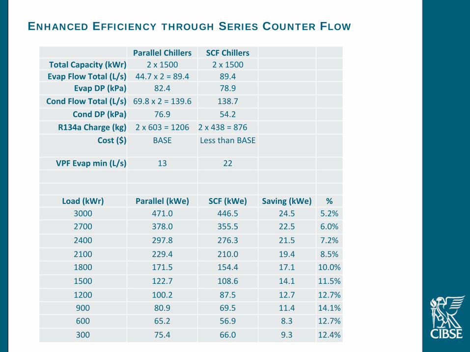
Parallel Chillers SCF ChillersTotal Capacity (kWr) 2 x 1500 2 x 1500Evap Flow Total (L/s) 44.7 x 2 = 89.4 89.4
Evap DP (kPa) 82.4 78.9Cond Flow Total (L/s) 69.8 x 2 = 139.6 138.7
Cond DP (kPa) 76.9 54.2R134a Charge (kg) 2 x 603 = 1206 2 x 438 = 876
Cost ($) BASE Less than BASE
VPF Evap min (L/s) 13 22
Load (kWr) Parallel (kWe) SCF (kWe) Saving (kWe) %3000 471.0 446.5 24.5 5.2%2700 378.0 355.5 22.5 6.0%2400 297.8 276.3 21.5 7.2%2100 229.4 210.0 19.4 8.5%1800 171.5 154.4 17.1 10.0%1500 122.7 108.6 14.1 11.5%1200 100.2 87.5 12.7 12.7%900 80.9 69.5 11.4 14.1%600 65.2 56.9 8.3 12.7%300 75.4 66.0 9.3 12.4%
ENHANCED EFFICIENCY THROUGH SERIES COUNTER FLOW