the grid roofnet: a rooftop ad hoc wireless network
TRANSCRIPT

The Grid Roofnet:
a Rooftop Ad Hoc Wireless Network
by
Benjamin A. Chambers
Submitted to the Department of Electrical Engineering and Computer
Sciencein partial fulfillment of the requirements for the degree of
Master of Engineering in Computer Science and Engineering
at the
MASSACHUSETTS INSTITUTE OF TECHNOLOGY
May 2002
c© Benjamin A. Chambers, MMII. All rights reserved.
The author hereby grants to MIT permission to reproduce anddistribute publicly paper and electronic copies of this thesis and to
grant others the right to do so.
Author . . . . . . . . . . . . . . . . . . . . . . . . . . . . . . . . . . . . . . . . . . . . . . . . . . . . . . . . . . . . . .
Department of Electrical Engineering and Computer Science27 May 2002
Certified by. . . . . . . . . . . . . . . . . . . . . . . . . . . . . . . . . . . . . . . . . . . . . . . . . . . . . . . . . .Robert T. Morris
Assistant Professor of Computer Science and EngineeringThesis Supervisor
Accepted by . . . . . . . . . . . . . . . . . . . . . . . . . . . . . . . . . . . . . . . . . . . . . . . . . . . . . . . . .Arthur C. Smith
Chairman, Department Committee on Graduate Students

2

The Grid Roofnet:
a Rooftop Ad Hoc Wireless Network
by
Benjamin A. Chambers
Submitted to the Department of Electrical Engineering and Computer Scienceon 27 May 2002, in partial fulfillment of the
requirements for the degree ofMaster of Engineering in Computer Science and Engineering
Abstract
This thesis describes the Grid Roofnet, a rooftop wireless Ad Hoc network built usingoff the shelf computers and 802.11 hardware along with special software. The Roofnetis a real-world testbed for wireless Ad Hoc networking research, and as a side effectalso provides network access to a small number of apartments in Cambridge, MA.
We describe the construction and performance of the network, and draw someconclusions about the viability of such networks and directions for future research.
Thesis Supervisor: Robert T. MorrisTitle: Assistant Professor of Computer Science and Engineering
3

4

Acknowledgments
This thesis is the result of joint work with Douglas S. J. De Couto and Daniel Aguayo.
In particular, I’m indebted to Doug for implementing most of Grid, for providing
much advice in debugging various things to get them to work on the Roofnet, and
for providing helpful comments on this thesis.
I’m similarly indebted to Dan, whose test scripts I used to evaluate the Roofnet’s
performance, and who was extremely helpful in answering my endless questions.
A great many thanks to Robert Morris for supporting such a cool project, and for
his guidance and advice on all aspects of this thesis.
M. Frans Kaashoek, for his generous purchase of the 40 foot ladder used to install
many of the antennas.
I’m very grateful to the members of PDOS for providing an enjoyable work en-
vironment. In particular, Chuck Blake, Jinyang Li, and Frank Dabek all provided
advice, assistance, and good company along the way. Chuck’s assistance went above
and beyond the call of duty, including assisting with the ladder on more than one
installation.
Of course, I owe a huge debt to all of the volunteers who hosted (and are still
hosting, as of this writing) Roofnet nodes in their apartments. Without their help,
this project would not have been possible. They are: Dina Katabi, Chuck Blake, Carl
Steinbach, James Robertson et al, Chandra Boyapati, Emil Sit, Andy Wheeler, and
Jim Morash, who went so far as to give me spare keys to his apartment so I could
come and go as I pleased. Thanks also to Professor Leslie Kaelbling for providing us
with space in her ninth floor lab area for one of our Roofnet nodes.
I am infinitely grateful to my parents, Don and Maggie Chambers, who have
provided me with unconditional support of every kind over the years, and also to the
rest of my very supportive family.
Finally, my many thanks to Madhulika, without whose motivating support the
timely completion of this thesis would not have been possible.
5

6
Contents
1 Introduction 9
1.1 Ad Hoc Networking . . . . . . . . . . . . . . . . . . . . . . . . . . . . 10
1.2 Grid Roofnet: an outdoor Ad Hoc wireless network . . . . . . . . . . 11
1.2.1 Challenges . . . . . . . . . . . . . . . . . . . . . . . . . . . . . 11
1.2.2 System Overview . . . . . . . . . . . . . . . . . . . . . . . . . 13
1.3 Thesis Overview . . . . . . . . . . . . . . . . . . . . . . . . . . . . . . 13
2 Related Work 15
2.1 Wireless Network Projects . . . . . . . . . . . . . . . . . . . . . . . . 15
2.2 Ad Hoc Routing Protocols . . . . . . . . . . . . . . . . . . . . . . . . 18
3 Roofnet 21
3.1 System Layout . . . . . . . . . . . . . . . . . . . . . . . . . . . . . . 21
3.2 Hardware . . . . . . . . . . . . . . . . . . . . . . . . . . . . . . . . . 21
3.2.1 Overview of 802.11 . . . . . . . . . . . . . . . . . . . . . . . . 24
3.2.2 Physical Layer . . . . . . . . . . . . . . . . . . . . . . . . . . . 24
3.2.3 MAC Layer . . . . . . . . . . . . . . . . . . . . . . . . . . . . 24
3.3 Software . . . . . . . . . . . . . . . . . . . . . . . . . . . . . . . . . . 25
3.3.1 Click . . . . . . . . . . . . . . . . . . . . . . . . . . . . . . . . 26
3.3.2 Other Grid Software . . . . . . . . . . . . . . . . . . . . . . . 26
3.3.3 Modifications . . . . . . . . . . . . . . . . . . . . . . . . . . . 28
3.4 Deployment . . . . . . . . . . . . . . . . . . . . . . . . . . . . . . . . 28
7
4 Evaluation 31
4.1 Quantitative Experiments . . . . . . . . . . . . . . . . . . . . . . . . 31
4.1.1 Broadcast Experiments . . . . . . . . . . . . . . . . . . . . . . 32
4.1.2 Broadcast Results . . . . . . . . . . . . . . . . . . . . . . . . . 33
4.1.3 Multi-Hop Path Measurements . . . . . . . . . . . . . . . . . 43
4.1.4 Multi-Hop Measurement Results . . . . . . . . . . . . . . . . . 44
4.1.5 Lessons from Experiments . . . . . . . . . . . . . . . . . . . . 46
4.2 Qualitative Evaluation . . . . . . . . . . . . . . . . . . . . . . . . . . 48
4.2.1 802.11 Problems . . . . . . . . . . . . . . . . . . . . . . . . . . 48
4.2.2 Antenna Height . . . . . . . . . . . . . . . . . . . . . . . . . . 50
5 Conclusions and Future Work 53
5.0.3 Lessons . . . . . . . . . . . . . . . . . . . . . . . . . . . . . . 53
5.0.4 Future Work . . . . . . . . . . . . . . . . . . . . . . . . . . . . 55
8

Chapter 1
Introduction
In recent years the popularity of wireless networking technology has increased dra-
matically, mostly due to the growing prevalence of mobile computing devices. Due to
its convenience, wireless networking is becoming more popular in traditional desktop
computers as well, and it seems likely that in the near future most computing devices
sold will come with some form of wireless technology.
If the users of wireless networking devices wish to communicate with other net-
worked devices, typically a static infrastructure such as a wireless access point or base
station must be set up ahead of time to provide the wireless devices with connectivity.
There are many situations, however, in which such a static infrastructure is either
inconvenient or impractical, but nonetheless communication is desired. For exam-
ple, users with mobile computers might want to collaborate on a group project in an
outdoor area where there are no wireless access points. Or, users in a neighborhood
might want to share files and communicate without having to pay for broadband
Internet access. Disaster scenarios where infrastructure may have been destroyed is
another situation in which communication without infrastructure would be desired.
In these cases, the wireless devices can arrange themselves into an Ad Hoc network.
9

1.1 Ad Hoc Networking
An Ad Hoc network is a collection of wireless nodes that form a network without the
use of any static infrastructure such as a wireless Access Point. Instead of commu-
nicating via a centralized access point, the nodes in the network cooperate to allow
information to be exchanged between them. In particular, each node acts as a router,
forwarding packets for other nodes in the network.
It is worth clarifying the definition of “Ad Hoc” used in this thesis, as there is some
confusion in wireless networking literature about this term. In particular, the IEEE
802.11 specification uses the term Ad Hoc to describe “a network composed solely
of stations within mutual communication range of each other” [10]. In many other
contexts, including this thesis, the term Ad Hoc refers to multi-hop self-configuring
wireless networks. This difference in definitions sheds some light on how well the
802.11 MAC layer performs as part of a multi-hop wireless network, and we discuss
these issues in Section 4.2.1.
The focus of most research in Ad Hoc networks is on finding efficient methods for
forwarding packets through the network. A number of different protocols for routing
in Ad Hoc networks have been proposed and evaluated in other work, and these are
briefly surveyed in Section 2.2.
Although a great deal of research has been done on Ad Hoc routing protocols,
relatively little real-world evaluation has been carried out. Most research published
on the topic has been evaluated only in simulation. While simulation can provide a
great deal of information about many properties of a routing algorithm, unfortunately
many real-world effects on a protocol’s performance cannot be predicted in simulation.
As Professor Rodney Brooks is fond of saying, “Simulations are doomed to succeed”.
For routing algorithms in particular, many simulations do not take into account the
actual behavior of links in the network. We find that certain metrics such as using
hop count to select routes simply do not perform properly in real wireless networks.
Simulations also do not model a variety of unexpected behavior that we have observed
in actual 802.11b hardware. One of our aims in this project was to build a testbed
10

where we could accurately measure various properties of real networks.
1.2 Grid Roofnet: an outdoor Ad Hoc wireless
network
This thesis presents the Grid Roofnet, an outdoor Ad Hoc wireless network testbed.
The Grid Roofnet was built with two objectives in mind. The first of these is to have
a real-world outdoor testbed on which to carry out experiments to evaluate various
Ad Hoc routing protocols. The second objective is to provide a usable network to
volunteers in East Cambridge that can be used to access the Internet and share files
or other information.
1.2.1 Challenges
From our initial discussions about building a rooftop network, it was clear that there
were a number of challenges to overcome, and in fact we were initially unconvinced
that such a network was feasible. Our group was already operating an indoor research
network, so our main challenges centered on making the network feasible outdoors
and over much greater inter-node distances.
Our hope was to deploy a rooftop network in the neighborhood immediately to the
North of the office building that houses our lab, and to have the network connected
to our lab by installing one of the Roofnet nodes in our building. This would allow
users of the Roofnet to connect to the Internet through our lab’s network connection,
which was attractive since we hoped it would provide the Roofnet’s users with a fairly
high bandwidth connection.
To start with, we believed that the distances involved would be pushing the limits
of the range of the available 802.11 hardware, if not exceeding them outright. A quick
survey of the effective range of most 802.11b adapters suggested that even outdoors
with no obstructions between nodes, we should not expect to reach further than 300
meters with the standard adapters and antennas. This was discouraging, since we
11

estimated the distance from our lab to the closest candidate apartment to be about
500 meters.
After conducting some research into available 802.11 antennas [8] we were pleased
to find Yagi (directional) antennas whose specifications claimed a range of over 3
kilometers, which we suspected would be sufficient for this first link. We acquired
a pair of Yagis and did some preliminary testing. Using the Yagis we were able to
establish a network link from one of the apartments closest to the lab (where node
29 is now located) to a test node on the ninth floor of our lab (where node 30 is now
located). See Figure 3-1 for node locations.
Once we had established the viability of the link from our lab to the neighborhood,
we set out to determine whether connectivity within the neighborhood itself was
feasible with the density of nodes that we expected to have. In this case we were
limited mostly by the density of graduate students and lab staff who were living in
that neighborhood. Because each node needed to be able to communicate with nodes
in all directions, we knew that the directional antenna used to solve the first link
problem would not be a viable solution for the rest of the nodes. So, we acquired a
pair of 5.2 dBi omnidirectional antennas and did some more testing.
In this second test, we set up a temporary omnidirectional antenna where node
32 is now located, and did a series of tests with another omnidirectional antenna
attached to a laptop computer in a car. We drove the car around the surrounding
neighborhood attempting to ping the fixed node in an effort to get a rough map of
the coverage of the omnidirectional antennas. In doing so we determined that the
node was intermittently reachable in a radius of several blocks. This convinced us
that the range was sufficient to be able to build a working network.
The remaining challenges mostly related to determining how to gain access to
the roofs of the volunteers’ apartments, and how to physically mount the antennas.
The former problem required getting the permission of many landlords and in several
cases the use of a ladder to physically get up onto the roof. Physically mounting
the antennas turned out to be fairly straightforward in most cases using standard
hardware. This is described in some detail in Section 3.
12
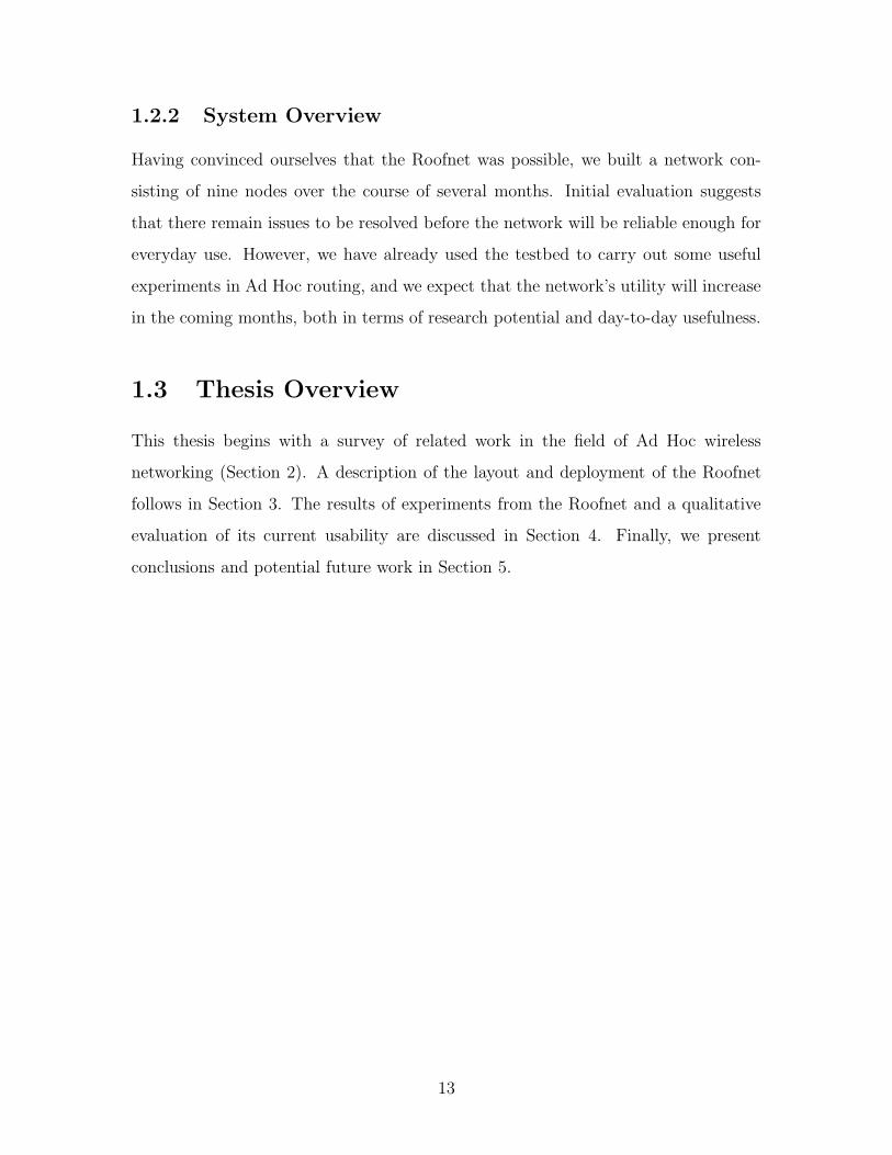
1.2.2 System Overview
Having convinced ourselves that the Roofnet was possible, we built a network con-
sisting of nine nodes over the course of several months. Initial evaluation suggests
that there remain issues to be resolved before the network will be reliable enough for
everyday use. However, we have already used the testbed to carry out some useful
experiments in Ad Hoc routing, and we expect that the network’s utility will increase
in the coming months, both in terms of research potential and day-to-day usefulness.
1.3 Thesis Overview
This thesis begins with a survey of related work in the field of Ad Hoc wireless
networking (Section 2). A description of the layout and deployment of the Roofnet
follows in Section 3. The results of experiments from the Roofnet and a qualitative
evaluation of its current usability are discussed in Section 4. Finally, we present
conclusions and potential future work in Section 5.
13

14

Chapter 2
Related Work
The Grid Roofnet shares similarities with a number of other wireless networking sys-
tems, which include research projects, commercial systems, and community projects.
A summary of these projects and their relationships to the Grid Roofnet are presented
below, as well as a brief summary of Ad Hoc routing protocols which we believe the
Roofnet will be helpful in evaluating.
2.1 Wireless Network Projects
Monarch project testbed
A testbed network originally developed at CMU as part of the Monarch project
[16, 17, 2] shares some of the goals of the Grid Roofnet, in particular the goal of
providing an outdoor physical testbed for evaluating the performance and properties
of Ad Hoc networking protocols. However, the Grid Roofnet has a number of major
differences both in its goals and implementation. The Monarch testbed used mobile
nodes mounted on cars to evaluate the performance of the DSR [13] protocol under
dynamic network topologies. This differs from the Roofnet’s static node locations,
and goal of providing usable Internet access to users in a neighborhood. Probably the
most significant difference between this testbed and the Grid Roofnet is the wireless
networking hardware used, which operated in the 900 Mhz range rather than the
15

2.4 Ghz range used by the Roofnet. Also, radios using the 802.11 standard were
unavailable when the Monarch testbed was being built, and as a result their radios
did not use 802.11. This probably turned out to be rather fortuitous for their system,
as we have found the 802.11 layer to be less than ideal for building a multi-hop wireless
network (see Section 4.2.1).
Nokia Rooftop
The Nokia Rooftop [4] is a commercial system capable of providing wireless broadband
Internet access to residential areas. In this regard it shares one of the goals of the Grid
Roofnet. However, because it is a commercial system and not a research platform,
the Nokia system uses a variety of specialized proprietary hardware and methods in
order to make their system perform well.
Nokia Rooftop uses proprietary 2.4 Ghz wireless routers [5] which do not use
the 802.11 standard. These routers use frequency-hopping radios which operate at
variable power levels between 16 mW and 500 mW, which at the high end is five
times the power output of the 802.11b radios used in the Grid Roofnet.
The Nokia Rooftop uses a proprietary routing protocol. This protocol uses su-
pernodes referred to as “AirHead routers” to route traffic between the mesh network
and the Internet. The system is structured to have in most cases no more than two
hops from a regular node to a supernode. The routing protocol uses a common radio
channel to cooperatively schedule non-interfering data burst transmissions between
pairs of nodes and uses multiple data channels simultaneously to maximize overall
network throughput [9]. The system uses these multiple channels along with dynamic
power control to avoid unnecessary interference between transmissions.
Ricochet MCDN
The Ricochet MicroCellular Data Network (MCDN) System [20] is a commercial net-
work providing Internet access to mobile users. The system provides Internet service
via a network architecture in which end users use a radio modem which communicates
with “microcells”. Packets from the user then pass from microcell to microcell until
16

they reach a wired backbone, at which point the packets are routed to the Internet.
The system uses proprietary routing algorithms to route packets from the microcells
to the wired backbone and back, and has special provisions to ensure that nodes that
are moving continue to stay in touch with microcells that are in radio range.
Although the Grid Roofnet and MCDN both share the very general goal of pro-
viding Internet access to end users via a multi-hop wireless network, the specific goals
and implementation of the MCDN system differ significantly from the Grid Roofnet.
First, the MCDN system’s primary goal is to provide network access to users who are
moving around, potentially at a high speed (up to 70 MPH). Consequently, much of
the system’s design is aimed at providing for a user’s radio to change rapidly between
microcells as the user moves from place to place. Second, due to its nature as a
commercial system, the network relies on a considerable static infrastructure, which
is different from the Roofnet goal of having no requirement for static infrastructure.
Lastly, the MCDN system uses a combination of radios operating in the 900 Mhz and
2.4 Ghz frequency ranges and like the Nokia Rooftop system, the radios do not use
the 802.11 standard.
WINGS and DAWN
The Wireless Internet Gateways (WINGS) [12] and the Density and Asymmetry-
adaptive Wireless Network (DAWN) [3] projects are both part of the DARPA Global
Mobile (GloMo) Information Systems program. Both address a number of issues
in wireless networking, but in general tackle problems more related to mobility and
military goals.
The WINGS project extends the Internet to multi-hop wireless networks using
an extension to the IP routing protocol. WINGS uses a MAC layer protocol called
FAMA-NCS that is somewhat similar to 802.11. A network layer protocol called
WIRP (Wireless Internet Routing Protocol) that uses Dijkstra’s shortest-path algo-
rithm over a hierarchical graph of the network is used for packet routing. The WINGS
project uses 900 Mhz radios which are not 802.11.
The goal of the DAWN project is to provide topologies for multi-hop wireless
17

networks which have a number of properties that are of particular importance in
tactical military networks. In particular, the project focuses on achieving reliability
by maintaining duplicate paths between all pairs of nodes in the network, while
attempting to reduce interference by keeping transmission power as low as possible.
In addition, the project presents ideas for adjusting the routing method based on
changing network density, for adjusting the network to compensate for jamming or
other interference, and to accommodate routing in the face of asymmetric links.
Community Wireless Networking
In recent years a large number of non-profit community wireless networking projects
have sprung up around the world. The goals of these projects vary, but generally
include sharing Internet access in communities, providing free Internet access in pub-
lic areas, and providing alternative networks that can be used to share information
outside of the Internet. In the simplest cases they may consist simply of a number of
individual users who have 802.11 access points connected to an Internet connection
and share their connection freely, while some more ambitious projects are working to
create metropolitan area wireless networks intended to augment the Internet. The
WirelessAnarchy project (http://wirelessanarchy.com/) has a fairly comprehen-
sive list of these projects, along with links to many wireless networking resources. A
small sampling of community wireless networking projects is listed in [6].
These projects clearly share the Grid Roofnet’s goal of providing Internet access
to communities, and similar to the Roofnet most such community networking projects
use 802.11b hardware and free software. However, these projects are primarily focused
on practical networking rather than research, and most of them do not use Ad Hoc
protocols.
2.2 Ad Hoc Routing Protocols
A number of different routing protocols have been proposed and evaluated (primarily
in simulation) in various work, and we believe it would be beneficial to use the Roofnet
18
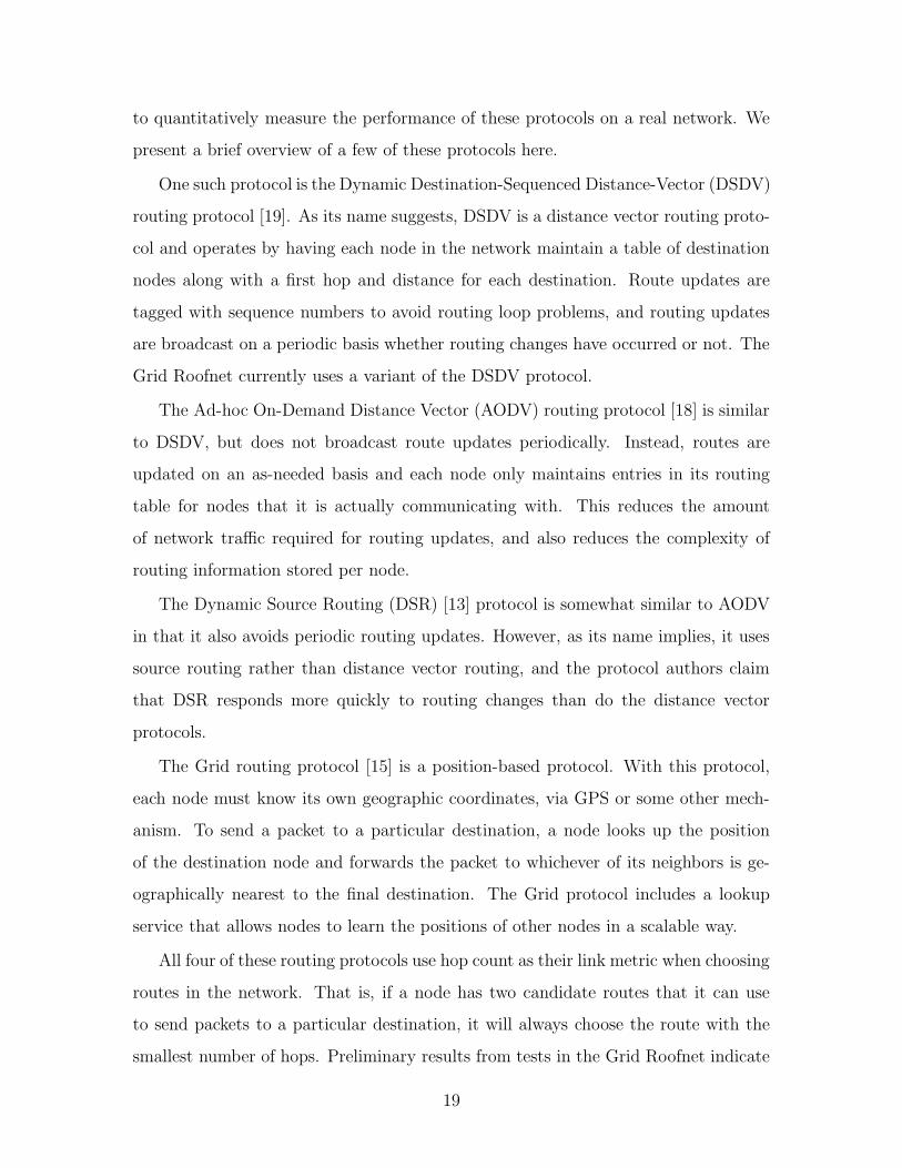
to quantitatively measure the performance of these protocols on a real network. We
present a brief overview of a few of these protocols here.
One such protocol is the Dynamic Destination-Sequenced Distance-Vector (DSDV)
routing protocol [19]. As its name suggests, DSDV is a distance vector routing proto-
col and operates by having each node in the network maintain a table of destination
nodes along with a first hop and distance for each destination. Route updates are
tagged with sequence numbers to avoid routing loop problems, and routing updates
are broadcast on a periodic basis whether routing changes have occurred or not. The
Grid Roofnet currently uses a variant of the DSDV protocol.
The Ad-hoc On-Demand Distance Vector (AODV) routing protocol [18] is similar
to DSDV, but does not broadcast route updates periodically. Instead, routes are
updated on an as-needed basis and each node only maintains entries in its routing
table for nodes that it is actually communicating with. This reduces the amount
of network traffic required for routing updates, and also reduces the complexity of
routing information stored per node.
The Dynamic Source Routing (DSR) [13] protocol is somewhat similar to AODV
in that it also avoids periodic routing updates. However, as its name implies, it uses
source routing rather than distance vector routing, and the protocol authors claim
that DSR responds more quickly to routing changes than do the distance vector
protocols.
The Grid routing protocol [15] is a position-based protocol. With this protocol,
each node must know its own geographic coordinates, via GPS or some other mech-
anism. To send a packet to a particular destination, a node looks up the position
of the destination node and forwards the packet to whichever of its neighbors is ge-
ographically nearest to the final destination. The Grid protocol includes a lookup
service that allows nodes to learn the positions of other nodes in a scalable way.
All four of these routing protocols use hop count as their link metric when choosing
routes in the network. That is, if a node has two candidate routes that it can use
to send packets to a particular destination, it will always choose the route with the
smallest number of hops. Preliminary results from tests in the Grid Roofnet indicate
19

that in many cases, the route with the smallest hop count is sub-optimal because
one or more of the links in the shortest route may be of lower quality than links in a
longer route. We believe that this and other factors warrant further in-depth testing
of all of the above protocols on the Roofnet.
20

Chapter 3
Roofnet
This chapter describes the layout of the Roofnet, the hardware and software that
make it up, and its deployment.
3.1 System Layout
The Grid Roofnet consists of nine network nodes deployed in East Cambridge, Mas-
sachusetts, near MIT’s Laboratory for Computer Science (LCS). The nodes are dis-
tributed over a region approximately one square kilometer in area. Nodes were in-
stalled in the apartments of volunteers, most of whom are other graduate students
at LCS. One node was installed on the ninth floor of LCS itself. Figure 3-1 shows
the locations of the nodes on a map of East Cambridge, and Table 3.1 shows the
approximate distance in meters between each pair of nodes.
3.2 Hardware
Roofnet nodes are built using off-the-shelf hardware. Each node consists of an Intel
Celeron-based computer with 128MB of RAM and a 20-30GB Hard Drive. The
computers were purchased over a period of roughly a year, and the clock speeds of
their processors vary from 500 Mhz to 1 Ghz, depending on their date of purchase.
Each node is equipped with two network interfaces. The first is a Cisco Aironet
21

29731 16
8
3534
32
30Approx. 300 m
Figure 3-1: A map of the Roofnet node locations. Nodes are labeled with their net-work identifier. Node 30 is located on the ninth floor of the Laboratory for ComputerScience and is equipped with a Yagi (directional) antenna, while the other eight nodesare equipped with omnidirectional antennas.
Node 35 34 32 31 30 29 16 8
7 300 250 300 60 600 180 250 4008 250 200 200 370 980 580 48016 500 400 300 230 710 28029 470 430 450 220 45030 800 800 880 65031 300 230 25032 300 22034 120
Table 3.1: Approximate distances between each pair of nodes in the Roofnet, inmeters.
22

Transmit Rate Auto (1, 2, 5.5, or 11 Mbps)Channel 4 (2427 MHz)Transmit Power 100 mWMode Ad HocAntenna 5.2 dBi omnidirectional or
13.5 dBi Yagi
Table 3.2: 802.11 settings
350 PCI 802.11b interface for communicating with the other nodes the the network.
The Aironet 350 adapters were chosen primarily because they feature a 100 mW
transmit power, which is more than three times as powerful as the 30 mW power
of most other 802.11b adapters. Since we knew that the distances between nodes
in the Roofnet would be pushing the limits of the hardware’s effective range, it was
important that we have as powerful a transmitter as possible at each node. Although
the FCC permits the transmit power of 802.11 radios to be as high as 1 Watt, the
100 mW transmit power of the Aironet 350 is the highest of any available 802.11b
card that we are aware of.
The second network interface is an ordinary 100BaseT Ethernet interface for con-
necting to an internal wired network in the volunteer’s apartment. The wired interface
allows the volunteer to connect to the Roofnet, and in some cases also provides a net-
work connection through the volunteer’s ISP that can be used to perform maintenance
on the node. These maintenance connections have proved themselves invaluable for
fixing network partitions, which are discussed in Section 4.2.1.
The 802.11b interface is connected via a low-loss cable to a 5.2 dBi omnidirectional
antenna [8], which is then mounted on the roof of the volunteer’s apartment building
or house. Most of the antennas were connected to the 802.11 interfaces with a 50 foot
long, 3.4 dB loss cable. However, node 30 uses a 20 foot long 1.3 dB loss cable and
node 35 uses a 75 foot long 5 dB loss cable. All cables were obtained from Cisco
Systems. Each antenna is mounted to a 5 foot long 1 1
4inch diameter steel antenna
mast, which is then attached to a chimney on the volunteer’s building using a chimney
mount [7].
23

Firmware Version 4Hardware Revision 00:22Software Revision 04:25Software Subrevision 00:05Interface Subrevision 00:00Bootblock Revision 01:50
Table 3.3: Cisco Aironet 350 details.
3.2.1 Overview of 802.11
This section briefly reviews some relevant details of the IEEE 802.11 standard for
wireless networks [11], which describes a set of protocols for the physical and MAC
layers. We consider only 802.11 in Ad Hoc mode, which allows nearby nodes to
communicate directly with each other, without any intervening access point.
3.2.2 Physical Layer
The physical layer used in this paper is direct sequence spread spectrum (DSSS). In
the United States, DSSS can be used on any of 11 channels centered every 5 MHz
from 2412 to 2462 MHz. Since channels must be at least 30 MHz apart to be non-
interfering [11, section 15.4.6.2], at most two completely non-interfering channels can
be used simultaneously. The standard defines modulation schemes for a variety of bit
rates ranging from 1 to 11 megabits per second (Mbps). Adapters can switch rates
for each packet they send.
3.2.3 MAC Layer
The 802.11 medium access control (MAC) layer provides mechanisms for carrier sense,
collision avoidance, and collision detection.
A node implements carrier sense by deferring transmission until it can hear no
other node. Broadcast packets are controlled by this mechanism alone.
Basic carrier sense is not sufficient in cases where the receiver is already receiving
a packet that the transmitter cannot hear. For this reason, 802.11 controls unicast
packets with an additional RTS/CTS mechanism. Before sending a data packet, the
24

sender sends a short RTS message; if the receiver gets the RTS and is idle, it returns
a CTS packet, giving the sender permission to send the whole data packet. To avoid
unnecessary overhead from RTS/CTS exchanges, they are disabled for data packets
whose size is less than the RTS threshold.
While carrier sense and RTS/CTS decrease the probability of collisions, they do
not eliminate them. 802.11 specifies that receivers return an ACK message for each
unicast packet successfully received. If the sender hears no ACK before a specified
timeout, it resends the packet after a backoff period. The maximum number of
retransmissions is a configurable parameter known as the short retry limit or long retry
limit, depending on the size of the packet. The 802.11 ACK mechanism addresses
both the problem of collisions between simultaneous transmissions, and the problem
of packets corrupted by noise or interference.
802.11 transmitters can fragment unicast packets larger than a specified fragment
threshold, allowing each fragment to be separately acknowledged or retransmitted.
The 802.11 specification calls for nodes to arrange themselves into Basic Service
Sets, which are groups of nodes that can communicate with each other. The details
and implications of this are discussed in Section 4.2.1.
3.3 Software
Grid Roofnet nodes run the OpenBSD 2.9 operating system and use a variant of the
DSDV [19] Ad Hoc routing protocol to forward packets between them. Although
the locations of the Roofnet nodes are static, the routing is not; routes are updated
dynamically by the routing protocol. This is useful since the quality of links varies
over time in spite of the fact that the nodes’ locations do not change. In addition,
it means that no configuration must be made when adding nodes to the network;
upon powering up, a node advertises its presence to neighboring nodes and becomes
included in the routing updates automatically. Grid’s packet routing is implemented
as a user space program with the Click modular router software [14].
25

3.3.1 Click
The Click software allows flexible routers to be built from modular software compo-
nents known as elements. Each element implements a particular part of the router’s
functionality, for example communicating with hardware devices, modifying pack-
ets, or determining where a packet should be sent based on its headers or contents.
Elements are written in C++, and a large number of Click elements were written
specifically for implementing Grid. A listing of Click elements, including the Grid
elements, is available online [1].
A Click router configuration is an interconnected collection of elements. Figure 3-
2 shows the Grid Click configuration. The Grid software receives packets from the
wireless device (FromDevice) and classifies them as one of several types. For example,
packets containing DSDV routing updates are sent to elements that maintain the local
routing table. Data packets are sent to the LookupLocalGridRoute element, where
they are either forwarded on to the next hop via the wireless device (ToDevice) or are
sent up to the higher protocol via the kernel interface (KernelTap) as appropriate.
Similarly, packets received from the kernel are routed appropriately.
On Roofnet nodes acting as a gateway, other elements (not depicted in Figure 3-
2) perform such functions as as Network Address Translation (NAT) and routing
between the wired and wireless networks.
One of the advantages of the Click software architecture is that it provides us a
very flexible framework from which we can easily test and evaluate different routing
protocols on our network. As of this writing we have only used our initial DSDV vari-
ant protocol, but deploying other protocols in the future will simply require writing
a few more Click elements and a new configuration file.
3.3.2 Other Grid Software
In addition to the Click router, a number of tools and helper programs have been
written to support the Grid software. These include perl scripts to run the Click
software and run various experiments, as well as a modified version of tcpdump that
26

li::LocationInfo
ControlSocket(tcp, 7777)
FromDevice
Classifier(...)
CheckGridHeader
Discard
nb::UpdateGridRoutes
Classifier(...)
Classifier(...)Classifier(...)
LocQueryResponderlr::LookupLocalGridRoute(nb)
Dis
card
fq::FloodingLocQuerier
geo::LookupGeographicGridRoute(nb)
Discard Discard
FixSrcLoc(li)
SetGridChecksum
ToDevice
KernelTap
Strip(14)
Classifier(...)Se
tIPA
ddre
ss(1
8.26
.7.1
)
Get
IPA
ddre
ss(1
6)
Che
ckIP
Hea
der
Discard
EtherEncap(...)
KernelTap
Grid protocol
IP Grid
IP bad found hop no hop
route broadcasts
found hop no hop bad
encap IP loc queryloc reply
reply for us- query for us-
local Grid Internet
encap IP loc query/reply
loc query encap IP/loc query
to FixSrcLoc
to LookupLocalGridRoute
Figure 3-2: The standard Grid Click configuration
27

recognizes the format of Grid packets. Another program, also written in perl, ex-
changes update messages with other Grid nodes and reboots the node if a period
of time passes without it hearing any updates. This has proven indispensable for
recovering from 802.11 BSSID partitions, which are discussed in Section 4.2.1.
3.3.3 Modifications
A number of small hacks were required to get the Grid software up and running on
the Roofnet.
One initial problem was that at the time we were deploying the Roofnet, the
OpenBSD airo driver for the Aironet cards did not support the Aironet 350 model
cards that we were using. To fix this, we had to apply a small patch to the device
definitions in the driver code.
A number of changes also needed to be made to the original Grid code, much of
which was hard coded for a particular range of IP addresses which the first (indoor)
Grid network used.
3.4 Deployment
The Grid Roofnet was deployed over a period of about four months. As previously
mentioned, all of the Roofnet nodes except for node 30 are housed in the apartment
buildings of volunteers. Node 30 is located on the ninth floor of our lab building, and
uses a directional antenna that is aimed out of a North facing window.
After determining that the network was viable, we solicited graduate students who
lived in the area to find volunteers willing to host the network nodes.
Once we had volunteers and had configured the computers with the appropriate
network adapters and software described above, all that remained was to install the
nodes. All but one of the houses hosting Grid Roofnet nodes are three stories high;
the house where node 32 is located is the exception and is only two stories high. All
of the buildings have flat roofs except the one hosting node 35, which has a somewhat
pitched roof. In buildings which have a stairway that leads to the roof, installation
28

was fairly straightforward. The antenna was mounted to a chimney as described
above, and a cable was run from the antenna down to the volunteer’s apartment,
generally by going in through a window, although in one case we ran the cable down
through the chimney of an unused fireplace.
For a few of the buildings we were installing at, there was no stairway providing
easy access to the roof. In these cases, the use of a ladder was required. We initially
purchased a 30 foot ladder for this purpose, but soon found that it was far too short
to reach the top of a three-story building. (In retrospect, this seems obvious). We
returned the ladder for a 40 foot model, which worked quite well. However, we learned
very quickly that 40 foot ladders are significantly more top-heavy than 30 foot ladders,
and require a bare minimum of two reasonably strong people to safely set them up;
three or more people make the task much more manageable.
29

30

Chapter 4
Evaluation
In this section we present several methods that we used to evaluate the performance
and usability of the Roofnet.
First, we describe quantitative experiments that we used to measure different
properties of the Roofnet. Second, we present our subjective evaluation of how useful
the network is in its present state, and comment on the prospects of improving it.
4.1 Quantitative Experiments
Here we present two sets of experiments that we ran to measure the quantitative
performance of the network. The first set of experiments that we performed measure
the loss rates between pairs of nodes in the network. The second set of experiments
measure the end-to-end throughput of statically routed packets sent through the
network. We present the results of both sets of experiments here, along with analysis
of their implications for the performance of Ad Hoc routing protocols.
Although there are nine Roofnet nodes installed currently, these tests were per-
formed when there were only seven nodes in the network. Our qualitative experience
so far has been that the addition of nodes to the network generally improves the
performance due to the availability of more routes, so if anything we would expect
these results to be improved somewhat when run over all nine current nodes.
31
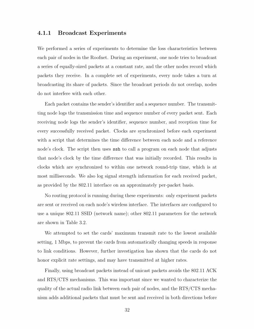
4.1.1 Broadcast Experiments
We performed a series of experiments to determine the loss characteristics between
each pair of nodes in the Roofnet. During an experiment, one node tries to broadcast
a series of equally-sized packets at a constant rate, and the other nodes record which
packets they receive. In a complete set of experiments, every node takes a turn at
broadcasting its share of packets. Since the broadcast periods do not overlap, nodes
do not interfere with each other.
Each packet contains the sender’s identifier and a sequence number. The transmit-
ting node logs the transmission time and sequence number of every packet sent. Each
receiving node logs the sender’s identifier, sequence number, and reception time for
every successfully received packet. Clocks are synchronized before each experiment
with a script that determines the time difference between each node and a reference
node’s clock. The script then uses ssh to call a program on each node that adjusts
that node’s clock by the time difference that was initially recorded. This results in
clocks which are synchronized to within one network round-trip time, which is at
most milliseconds. We also log signal strength information for each received packet,
as provided by the 802.11 interface on an approximately per-packet basis.
No routing protocol is running during these experiments: only experiment packets
are sent or received on each node’s wireless interface. The interfaces are configured to
use a unique 802.11 SSID (network name); other 802.11 parameters for the network
are shown in Table 3.2.
We attempted to set the cards’ maximum transmit rate to the lowest available
setting, 1 Mbps, to prevent the cards from automatically changing speeds in response
to link conditions. However, further investigation has shown that the cards do not
honor explicit rate settings, and may have transmitted at higher rates.
Finally, using broadcast packets instead of unicast packets avoids the 802.11 ACK
and RTS/CTS mechanisms. This was important since we wanted to characterize the
quality of the actual radio link between each pair of nodes, and the RTS/CTS mecha-
nism adds additional packets that must be sent and received in both directions before
32

a packet can be received. Among other things, this would make the detection of
asymmetric links very difficult. In addition, because unicast packets may be retrans-
mitted many times until they are acknowledged, the actual loss rate is often masked
by the MAC layer. Using broadcast packets avoided this problem as well, and allowed
us to collect data which accurately reflected the quality of the links themselves.
We performed experiments with big and small packets. Small packets were 50
bytes (8 bytes data plus UDP, IP, and Ethernet headers), roughly approximating the
size of 802.11 RTS/CTS and ACK packets. (802.11 RTS/CTS and ACK packets are
34 bytes each.) These 50 byte packets were sent at 1024 packets per second. Big
packets were 1024 bytes, more representative of large data transfers. These were sent
at 50 packets per second, at an even rate. The result is a send rate of somewhat
more than 400,000 bits per second, due to 802.11 headers. This should be well below
the minimum 802.11 capacity of 1 megabit per second. However, on some occasions
nodes were not able to broadcast at the desired rate, perhaps because of 802.11 traffic
outside our control, or to interference appearing to the card as carrier.
4.1.2 Broadcast Results
Link Variation
We conducted two sets of experiments with the Roofnet in the evening of Wednesday
6 March 2002, one for small packets (6-Mar-18:30-50-byte) and one for large packets
(6-Mar-19:30-1024-byte). Each node transmitted for 300 seconds during each set of
tests.
Figure 4-1 shows the cumulative distribution of delivery rates across all links for
each packet size. The two directions between each node pair are considered to be
separate links.
The figure shows that about 50% of the links deliver no packets, while the best 20%
of links deliver more than 95% of their packets. The delivery rates of the remaining
links are evenly distributed. Other experiments on different days, at different times,
and with different parameters confirm that in general the links in the network exhibit
33

0
0.2
0.4
0.6
0.8
1
0 0.2 0.4 0.6 0.8 1
Cum
ulat
ive
Frac
tion
of L
inks
Delivery rate
6-Mar-19:30-1024-byte6-Mar-18:30-50-byte
Figure 4-1: Cumulative distribution of per-link delivery rates on the Grid Roofnet.Note that many links are of intermediate quality.
a wide range of delivery rates.
As we discuss in section 4.1.5, the wide variation in delivery rates suggests that
shortest-path routing will not work well on these networks.
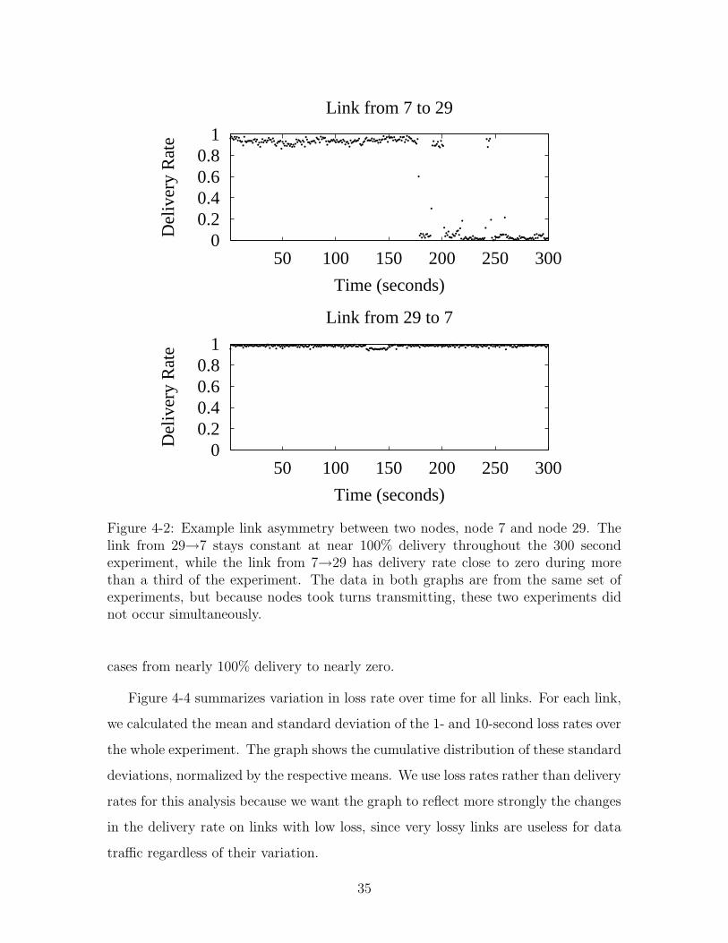
Link Asymmetry
Figure 4-2 shows the delivery rates for the two links (one in each direction) between
a pair of nodes in the 6-Mar-18:30-50-byte experiment. While the delivery rate from
29→7 stays nearly constant at 100% delivery, the link from 7→29 drops to nearly
zero delivery for more than a third of the experiment. This figure suggests that at
times, certain pairs of nodes may have highly asymmetric links between them.
Link Variation Over Time
Figure 4-3 shows the second-by-second delivery rates for three links from the exper-
iment 6-Mar-18:30-50-byte. The graphs show that while delivery rates are generally
stable, they can sometimes change very quickly and over a dramatic range, in some
34
00.20.40.60.8
1
50 100 150 200 250 300
Del
iver
y R
ate
Time (seconds)
Link from 7 to 29
00.20.40.60.8
1
50 100 150 200 250 300
Del
iver
y R
ate
Time (seconds)
Link from 29 to 7
Figure 4-2: Example link asymmetry between two nodes, node 7 and node 29. Thelink from 29→7 stays constant at near 100% delivery throughout the 300 secondexperiment, while the link from 7→29 has delivery rate close to zero during morethan a third of the experiment. The data in both graphs are from the same set ofexperiments, but because nodes took turns transmitting, these two experiments didnot occur simultaneously.
cases from nearly 100% delivery to nearly zero.
Figure 4-4 summarizes variation in loss rate over time for all links. For each link,
we calculated the mean and standard deviation of the 1- and 10-second loss rates over
the whole experiment. The graph shows the cumulative distribution of these standard
deviations, normalized by the respective means. We use loss rates rather than delivery
rates for this analysis because we want the graph to reflect more strongly the changes
in the delivery rate on links with low loss, since very lossy links are useless for data
traffic regardless of their variation.
35

Results for 1 and 10-second windows show that quite a few links vary greatly
on these times scales. For example, nearly half of the links had standard deviations
in their 1-second loss rates that exceeded half of the mean 1-second loss rate. This
suggests that wireless routing protocols should use agile predictors of link loss rates.
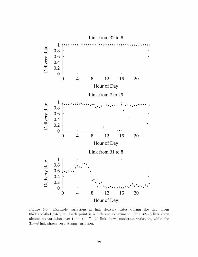
A third set of experiments (05-Mar-24h-1024-byte) was performed over a 24-hour
period to examine the variation in link performance throughout the day. Each ex-
periment was 30 minutes long, during which each node attempted to broadcast 100
1024-byte packets per second for 60 seconds. Many links showed daily variations;
some example link delivery rates are shown in Figure 4-5.
Because the physical obstructions at rooftop heights do not change significantly
over the course of a 24 hour period, there was not as much variation in the Roofnet
links as one might expect to see in an indoor network where obstructions such as
doors and people move on an hourly basis. The variation that we did observe in
the Roofnet over the course of a day were likely due to changing patterns of RF
interference in the area. In particular, devices such as cordless telephones, microwave
ovens, and of course 802.11b networking equipment all emit signals in the 2.4 Ghz
band. We believe that a combination of these devices’ effects could be impacting the
quality of certain links.
36

00.20.40.60.8
1
50 100 150 200 250 300
Del
iver
y R
ate
Time (seconds)
Link from 16 to 8
00.20.40.60.8
1
50 100 150 200 250 300
Del
iver
y R
ate
Time (seconds)
Link from 31 to 29
00.20.40.60.8
1
50 100 150 200 250 300
Del
iver
y R
ate
Time (seconds)
Link from 7 to 29
Figure 4-3: Example per-second variation in link delivery rates. Each point is thedelivery rate over one second during 6-Mar-18:30-50-byte. The delivery rate of the16→8 link fluctuates on a time-scale of seconds, while the 31→29 link is comparativelystable. The 7→29 link starts at near 100% delivery, but drops off to near zero partwaythrough the experiment.
37

0
0.2
0.4
0.6
0.8
1
0 0.5 1 1.5 2 2.5 3
Cum
ulat
ive
Frac
tion
of L
inks
Loss Rate Std. Dev. (normalized)
1 sec10 secs
Figure 4-4: The cumulative distribution of the normalized standard deviation ofshort-term link loss rates calculated over 1 and 10 second intervals on the Roofnet(6-Mar-18:30-50-byte). Many links show significant variation in short-term loss ratesover time.
38
00.20.40.60.8
1
0 4 8 12 16 20
Del
iver
y R
ate
Hour of Day
Link from 32 to 8
00.20.40.60.8
1
0 4 8 12 16 20
Del
iver
y R
ate
Hour of Day
Link from 7 to 29
00.20.40.60.8
1
0 4 8 12 16 20
Del
iver
y R
ate
Hour of Day
Link from 31 to 8
Figure 4-5: Example variations in link delivery rates during the day, from05-Mar-24h-1024-byte. Each point is a different experiment. The 32→8 link showalmost no variation over time, the 7→29 link shows moderate variation, while the31→8 link shows very strong variation.
39

00.10.20.30.40.50.60.70.80.9
1
0 100 200 300 400 500 600 700 800 900
Del
iver
y R
ate
Distance Between Node Pair, meters
Delivery Rate vs. Inter-Pair Distance
Figure 4-6: Delivery rate vs. approximate distance between each node pair, from the6-Mar-18:30-50-byte experiment.
Distance/Delivery Correlation
Figure 4-6 shows a plot of delivery rate versus the distance between pairs of nodes
from the 6-Mar-18:30-50-byte experiment. Table 4.1 lists the corresponding pairs of
source and destination nodes and the distance and delivery rate between each pair.
The two directions of a link are considered to be different pairs. Pairs for which the
delivery rate was zero are not shown in the graph or the table.
As is to be expected, there is a rough inverse correlation between delivery rate
and distance; in general, the further apart two nodes are, the lower the delivery rate
between them. Most of the pairs with delivery rates above 90% are within 300 meters
of each other.
However, the correlation is not strict. In many cases, pairs with a smaller separa-
tion have delivery rates that are lower than pairs with larger separations. This can
be seen in Figure 4-6, as there are a number of node pairs whose separation is less
than 300 meters and yet whose delivery rate is very low. This is most likely due to
obstructions such as trees and buildings between those pairs of nodes.
40

Node Pair Distance Delivery Rate
31,7 60 0.9917,31 60 0.9957,29 180 0.61429,7 180 0.98032,8 200 0.99631,29 220 0.95529,31 220 0.99331,16 230 0.97316,31 230 0.99132,31 250 8.54e-516,7 250 2.53e-431,32 250 0.10416,29 280 0.09029,16 280 0.99232,7 300 8.91e-57,32 300 0.03116,32 300 0.95332,16 300 0.96031,8 370 0.35332,29 450 0.16729,32 450 0.35216,8 480 0.46430,7 600 0.8087,30 600 0.90731,30 650 0.93230,31 650 0.97730,32 880 0.067
Table 4.1: Delivery rate and approximate distance between pairs of nodes in theRoofnet from the 6-Mar-18:30-50-byte experiment. Distance is in meters. Pairs aresorted first by increasing inter-node distance, then by increasing delivery rate.
41

All of the node pairs with a distance of 600 meters or more are links two or from
node 30. The relatively high delivery rate of some of these pairs is probably explained
by the fact that node 30 is at a much higher elevation than the other nodes and uses
a directional antenna. As a result, many of the nodes’ antennas have a line of sight
connection to node 30 in spite of the large distance between them.
42
4.1.3 Multi-Hop Path Measurements
We also performed experiments to get a baseline estimate of the end-to-end through-
put that we should expect to see in the network. This is useful for comparison when
evaluating the end-to-end performance of various routing protocols on the network,
such as DSDV, DSR, and others. Our specific goal was to compare the quality of
different routes between a given pair of source and destination nodes.
To accomplish this, we ran tests which sent 1024-byte UDP packets via static
routes through the network.
First, we used the data from the broadcast tests to estimate the packet delivery
rate across each link, and then calculated what the most promising routes were for
each pair of source and destination nodes. The most promising routes were picked
based on the expected number of transmissions needed for the packet to arrive at
its destination if sent along that route. The formula used to calculate the expected
number of transmissions per link was
E[r] = 1
P
where P is the delivery rate on that link, as measured in our broadcast tests. To
find the expected number of transmissions for a route, the expected transmissions for
each link along that route were summed.
We then took the two most promising looking routes (i.e., the two routes with the
smallest expected number of transmissions) for each source/destination pair and sent
packets along each of those routes. Two routes were used so that we could compare
between different routes for each pair of source and destination nodes. We could have
used more than two routes per pair, but we chose to use two for simplicity.
Nodes took turns sending packets, so that no two nodes were sending simulta-
neously. Each sending node sent packets for a total of fifteen seconds along each
route, logging the source, destination, sequence number, time sent, and route used
for each packet sent. Similarly, for every packet received each node recorded the
source, destination, sequence number, time received, and the route used to send the
packet.
43

050
100150200250300350400
0 2 4 6 8 10 12Thr
ough
put,
Pack
ets
per
Seco
nd
Node Source/Destination Pair
Route Performance by Pair
Route 1Route 2
Figure 4-7: Transmission rates for different routes between pairs of nodes in theRoofnet.
Each sending node sent packets as fast as it could, ensuring that the total through-
put that we recorded was in fact the highest performance that the network could
handle.
4.1.4 Multi-Hop Measurement Results
To evaluate the quality of each route, we examined the receive logs to determine
the total number of packets received along each route, and calculated the average
transmission rate for each.
Unfortunately, no packets were received along many of the tested routes, and as
a result most of the pairs of source and destination routes received packets along one
or fewer routes. We speculate that this is due to some of the partitioning issues we
have had with the 802.11 hardware (see Section 4.2.1). However, we present here the
data for those pairs which received packets along both tested routes. We have found
that even in this subset of routes there are interesting results.
Table 4.2 shows the transmission rates along two different routes for each of eleven
44

Pair Number Node Pair Route Transmission Rate
1 29,7 29 → 7 9.629 → 31 → 7 10.2
2 29,16 29 → 16 9.229 → 31 → 16 8.9
3 29,30 29 → 31 → 30 10.229 → 7 → 30 10.0
4 29,31 29 → 31 9.929 → 16 → 31 8.1
5 29,32 29 → 16 → 32 9.429 → 31 → 16 → 32 10.3
6 16,7 16 → 31 → 7 357.016 → 29 → 7 122.9
7 16,29 16 → 29 333.216 → 31 → 29 258.4
8 16,30 16 → 31 → 30 135.416 → 31 → 7 → 30 111.2
9 16,31 16 → 31 160.216 → 29 → 31 290.8
10 30,7 30 → 7 315.430 → 31 → 7 356.0
11 30,31 30 → 31 371.330 → 7 → 31 290.6
Table 4.2: Transmission rates for different routes between pairs of nodes. Throughputis in 1024-byte packets per second. Some longer routes have higher throughputs.
45

source and destination node pairs. Not surprisingly, different routes have widely
varied throughputs, with some routes receiving almost no packets. Since all of the
routes that performed extremely poorly had node 29 as their source, it seems likely
that interference or some other factor was causing node 29’s transmissions to be
poorly received.
Figure 4-7 shows a graph of the same data, with the transmission rates for each
pair’s routes plotted for comparison. When the routes for a pair of nodes differ in
hop count, Route 1 always refers to the route with the shorter hop count.
What is interesting about the results of this test is the fact that in some cases, the
routes with higher transmission rates have more hops. For example, there are two
routes for the pair {16,31}. One of these, the 16 → 31 route, is a one-hop (direct)
route, while the other, 16 → 29 → 31 is a two-hop route through node 29. The
2-hop route has roughly twice the end-to-end throughput of the one-hop route. This
is shown as pair 9 in Figure 4-7. Similarly, pair 10 shows a 3-hop route with higher
end-to-end throughput than a 2-hop route.
4.1.5 Lessons from Experiments
The results of the broadcast tests have a number of implications for how we should
expect Ad Hoc routing protocols to perform on real-world networks. In particular, we
observed that the links in real wireless networks vary widely in their delivery rates,
that some links are asymmetric, that link delivery rates can vary quickly, and that
distance and obstructions both play a role in link quality.
Link Variation
Most routing protocols use hop count as their link metric: they try to choose routes
with the smallest number of links. This works well if all links have similar charac-
teristics, which means using a longer route won’t improve end-to-end performance.
However, as we showed above, wireless links can offer a wide range of delivery rates.
In this case, a longer route made up of links with high delivery rates can have bet-
46

ter end-to-end performance than a shorter route which is made up of links with low
delivery rates.
This result was shown dramatically with our multi-hop end-to-end tests, in which
some routes with longer hop counts performed significantly better than routes with
shorter hop counts.
Link Asymmetry
Our results show that some wireless links have asymmetric delivery rates. This means
that low-loss delivery of routing updates in one direction does not mean that sending
data back along the route will work well. It turns out to be hard to take advantage of
asymmetric links with protocols (such as 802.11) that use link-layer acknowledgments.
The best approach to asymmetric links, therefore, is to recognize and avoid them if
possible.
Link Variation Over Time
We found that link performance varies over several different time scales, from hours
to seconds. A routing protocol could measure, for example, the delivery rate of its
routing updates, and use these to predict link quality. However, since calculating
precise delivery rates requires counting lost and received packets over many transmis-
sions, direct measurements may not react quickly enough to frequent changes in link
performance.
Distance/Delivery correlation
The last result is that while in general nodes that are further apart have lower delivery
rates, in many cases links between nodes that are comparatively close together fare
worse than links between more separated nodes. This is likely a function of factors
such as physical obstructions between nodes and variable amounts of RF interference.
47
4.2 Qualitative Evaluation
In this section, we present a brief analysis of the practical usability of the Roofnet in
its current state.
As of this writing, the Roofnet is fairly unreliable. While there are a number of
possible explanations for why this is the case, fundamentally we do not yet understand
quite why this is. However, we believe that most of the problems stem from instability
in the Ad Hoc mode of the 802.11b hardware that we are using. These issues are
discussed below.
In addition, we present a brief qualitative evaluation of the effect of antenna height
on link performance.
4.2.1 802.11 Problems
Most of the problems we’ve encountered in running the Roofnet have been related to
various bugs or problems with the Aironet firmware, and/or fundamental limitations
to the 802.11b MAC layer that are counterproductive to Ad Hoc networking.
BSSID partitioning
When 802.11 interfaces are put into Ad Hoc mode, they go through a somewhat
complicated procedure to join what is known as a Basic Service Set, or BSS [11]. A
BSS is a kind of virtual network; even if two different nodes are operating on the
same channel, they will not “see” each other’s packets unless they are in the same
BSS. Basic Service Sets are identified by a 6-byte number known as the Basic Service
Set ID, or BSSID, which is transmitted in the header of every 802.11 frame.
When an 802.11b adapter enters Ad Hoc mode, it is configured with a Service Set
ID (SSID), which is a string that is intended to identify the network it wishes to join.
The adapter then scans through all of the 802.11b channels, listening for beacons sent
by other nodes. Beacons contain, among other things, the SSID and BSSID being
used by the sending node. If the adapter hears a beacon containing the SSID that
matches its own, then it joins this existing Basic Service Set by setting its own BSSID
48

to the one received in the beacon.
If the adapter does not receive any beacons with a matching SSID within a certain
period of time, it decides that no Basic Service Set currently exists with its SSID. In
this case, it sets up itself as a new Basic Service Set by selecting a random BSSID and
using that for all of its traffic. Any other nodes using the same SSID which start up
in range of this node will hear its beacons and configure themselves to use its BSSID.
This creates a serious problem for an Ad Hoc network. Namely, if two nodes start
up at different times and are not within radio range of each other, they will start with
different BSSIDs and be on different logical networks, despite both having the same
SSID. Because 802.11 adapters ignore all frames whose BSSID does not match their
own, this creates a partition in the network and prevents all of the nodes from being
able to communicate properly. Ideally, it would be possible to set the BSSID directly
to ensure that a given set of nodes would all be able to communicate. Unfortunately,
this is not possible using 802.11b hardware.
Firmware Bugs
Along the way, we have encountered some strange behavior from our 802.11b adapters,
which we attribute to problems in the adapters’ firmware.
The first bug we encountered was related to the partitioning explained above.
As previously mentioned, the BSSID is a 6-byte number. It is usually denoted in
hexadecimal format, with colons between each byte, e.g. 02:04:e3:f8:d2:20. The
Aironet adapters had the somewhat odd behavior in which they would set their
BSSID to “all ones” (ff:ff:ff:ff:ff:ff) while they were scanning for other nodes’
beacons. Unfortunately, if two of the nodes started up at roughly the same time and
were thus scanning simultaneously, they would see beacons from the other node and
would both set their BSSIDs to ff:ff:ff:ff:ff:ff, causing a partition as explained
above.
This problem was mostly solved by having each node sleep for a random period
of time when it first starts up, which makes it very rare for nodes to start up simul-
taneously and end up on the “all ones” BSSID. However, we still see this behavior
49

occasionally.
A second and much more troubling behavior that we have seen involves inexpli-
cable partitioning of the network. Specifically, all of the network nodes will start up
and correctly converge to a unique BSSID. As previously explained, in theory any
two nodes using the same channel and BSSID should be able to receive each other’s
packets. However, we have observed that in some cases the nodes will form two dis-
joint groups, each of which receive packets only from nodes in their group, but not
from any nodes in the other group. All of the nodes in both groups report the same
SSID, BSSID, and channel; the only observable difference between the two groups is
the fact that some of them cannot receive others’ packets. It is tempting to think that
this happens merely because of poor link quality between certain nodes. However,
this is not the case, and these partitions are not “natural” partitions in the sense
that they might have occurred simply due to poor connectivity in the topology of the
network. In particular, we’ve observed nodes 31 and 7 to be disconnected in this way
on multiple occasions. Nodes 31 and 7 are less than 100 meters apart with direct line
of sight between their antennas, so the likelihood of their being out of radio range
from each other is effectively zero. More importantly, our qualitative experience has
been that the link between nodes 31 and 7 works perfectly (i.e. with effectively zero
loss) greater than 95% of the time. When the link does not work, as described above,
nodes 31 and 7 receive none of each other’s packets, despite both nodes being in
communication with disjoint sets of other neighboring nodes.
As of this writing, the cause of this partitioning is unknown to us. Determin-
ing what causes this phenomenon would be a great help, since it currently causes
significant instability in the Roofnet.
4.2.2 Antenna Height
While we have not yet performed formal analysis of the correlation between antenna
height and link performance, we feel that it may be useful to share our observations.
As mentioned earlier, all but one of the houses hosting Roofnet nodes are three
stories high. This means that in general the top of their roofs are roughly 30 to 40 feet
50

above the ground. The Roofnet antennas are mounted to 5 foot long masts, which
are then attached to a chimney on the roof of each building. Our best estimate is
that most of the antennas are approximately 7-10 feet above the height of the roof,
suggesting that the antennas themselves are between 37 and 50 feet above the ground.
The one exception to this is node 32’s antenna. Because node 32 is in a two story
apartment building, we anticipated that its lowered height would be problematic
for communicating with other nodes. We attempted to compensate by mounting
its antenna using two interconnected 5 foot long masts, rather than just one. This
increased its height to roughly 10 feet above the top of the roof. Even so, we estimate
that the antenna’s height is most likely between 30 and 35 feet above the ground,
which is still lower than most of the other nodes.
The most important factor in performance of antennas is to have line of sight
contact between the two antennas if at all possible. This means that both antennas
should be at roughly the same height and there should be no physical obstructions
between them.
Trees and other buildings are the most common obstructions in residental envi-
ronments such as the one in which the Roofnet was deployed. Trees are problematic
because being full of water, they strongly attenuate signals in the 2.4 Ghz range used
by the Roofnet’s 802.11b radios. Buildings are also a problem in that they reflect
and scatter signals, reducing their ability to reach their destination. There are no
buildings taller than three stories in the neighborhood where the Roofnet was de-
ployed, and mounting antennas 5-10 feet above the height of three story buildings
avoids nearly all of the building obstructions, and most of the trees.
Not surprisingly, we have noticed a significant difference in the quality of links to
and from node 32. Due to the taller buildings and trees that node 32’s antenna fails
to reach above, links to and from node 32 are for the most part significantly worse
than most of the links between other pairs of nodes.
Our rather unsurprising conclusion is that in order to maximize the quality of links
between nodes, antennas should be mounted as high as possible to avoid obstructions
such as trees and other buildings. While this is fairly obvious, nevertheless we have
51

found it to be a significant factor in the performance of the network, and we believe
that having as many antennas as possible have unobstructed views of each other is
crucial to having a successful network of this kind.
52
Chapter 5
Conclusions and Future Work
We have presented the Grid Roofnet, an outdoor wireless Ad Hoc network testbed.
To date, the Roofnet is not as usable for everyday Internet access as we had hoped.
However, we have run a number of interesting experiments on the Roofnet already
and we expect that it will be useful for a variety of other experiments in the future.
In addition, we hope to do more work to improve its reliability.
5.0.3 Lessons
During the course of building and testing the Roofnet, we have learned a variety of
valuable lessons, both from a practical standpoint of building such a network, and
from a theoretical standpoint in terms of what we think are likely to be promising
routing algorithms. We summarize these lessons below.
• Link quality varies considerably and is not bimodal
The quality of links in wireless networks varies greatly; the variation occurs
both from one link to another and in individual links over time. In addition,
link quality is not bimodal. In other words, many links have delivery rates
that are of intermediate quality; they neither deliver all sent packets, nor do
all sent packets fail. The implication of this is that in many cases, routes with
fewer hops may actually have worse performance, because the individual links
are of lower quality than the links in a longer route. This was directly shown
53

in our multi-hop path measurements, in which several routes were shown to
have significantly better performance than routes with fewer hops to the same
destination. This result is significant since most Ad Hoc routing protocols
always pick the route with the smallest number of hops. We believe that a
different metric, for example one which takes into account the total number of
transmissions that are expected along each route, should be used instead of hop
count for route selection.
• Some links are asymmetric
In addition, we found that some links are asymmetric. This violates the assump-
tions of a number of routing protocols which assume that receiving a routing
update in one direction implies that communication is possible in the other
direction. We believe that, in particular when using a MAC protocol such as
802.11 which uses link-layer acknowledgments, it is best to avoid asymmetric
routes if possible.
• Distance and antenna height affect delivery rate
Unsurprisingly, we found that the links that performed the best were those be-
tween nodes that were close together and did not have any obstructions blocking
their antennas. Obstructions seem to affect delivery rate more than distance, as
we found a number of links over comparatively long distances that performed
better than links over shorter distances. We believe that most of these shorter
links with poor performance had some kind of physical obstruction blocking
them, although some of the poor performance could be caused by RF interfer-
ence. Antenna height is a factor to the extent that higher antennas tend to
have fewer obstructions between them and other nodes.
• 802.11 is non ideal for multi-hop wireless networks
We found that for practical reasons, the 802.11 MAC protocol is an undesirable
layer upon which to build a multi-hop Ad Hoc network. Our primary issue has
been that the BSS mechanism in 802.11 adds an undesired layer of complexity
54

below the routing protocol that in many cases has caused partitions in our
network. In many cases, even when all the network nodes have converged to
the same BSS, we have observed partitioning effects that we cannot explain as
a result of network topology or effects of our higher level protocols.
We believe that a MAC protocol which is more flexible in determining which
nodes can communicate with each other would be more appropriate for multi-
hop wireless networks.
5.0.4 Future Work
We believe that there is considerable opportunity to learn more from the Grid Roofnet.
To start with, we would like to conduct tests to understand exactly what effects at
the MAC layer are causing the instability we have observed in the Roofnet.
In addition, we would like to re-run the multi-hop path measurements with a
larger number of routes per pair of nodes in order to get a more complete picture of
the capacity of different routes.
Lastly, we would like to carry out in depth measurements comparing the perfor-
mance of a number of different Ad Hoc routing protocols on our network.
Overall, building the Roofnet has proved to be a very valuable experience, and we
expect that it will continue to prove its usefulness from both research and practical
standpoints in the future.
55

56
Bibliography
[1] Click documentation index. http://pdos.lcs.mit.edu/click/doc/.
[2] CMU/Rice Monarch Project. http://www.monarch.cs.rice.edu/.
[3] Density and Asymmetry-adaptive Wireless Network (DAWN). http://www.
net-tech.bbn.com/projects/dawn/dawn-index.html.
[4] Nokia Rooftop. http://http://www.nwr.nokia.com/.
[5] Nokia Rooftop Wireless Router Data Sheet. http://www.nwr.nokia.com/docs/
WRdatasheetV3.pdf.
[6] Various Community Wireless Networking Projects.
http://www.bawug.org
http://www.guerilla.net
http://www.houstonwireless.org
http://awip.truffula.net
http://austinwireless.net
http://www.milehighwireless.net
http://free2air.org
http://consume.net
http://bcwireless.net
http://www.houstonwireless.org
http://nycwireless.net
http://wirelessanarchy.com
57

http://nocat.net
http://personaltelco.net .
[7] Antenna Masts and Mounts – HomeTech Solutions, 2001. http://www.
hometech.com/video/antmount.html#CM-9064.
[8] Cisco Aironet Antenna Reference Guide. Cisco Systems Inc., April 2002. http://
www.cisco.com/warp/public/cc/pd/witc/ao350ap/prodlit/agder_rg.htm.
[9] Nokia RoofTop Wireless Routing White Paper, 2002. http://www.nwr.nokia.
com/docs/White_Paper_Ver2.pdf.
[10] David Beyer. Fundamental characteristics and benefits of wireless routing
(’mesh’) networks. In Wireless Communications Association Technical Sympo-
sium, January 2002.
[11] IEEE Computer Society LAN MAN Standards Committee. Wireless LAN
Medium Access Control (MAC) and Physical Layer (PHY) Specifications. New
York, New York, 1997. IEEE Std. 802.11–1997.
[12] J. Garcia-Luna-Aceves, C. Fullmer, E. Madruga, D. Beyer, and T. Frivold. Wire-
less Internet Gateways (WINGS), 1997.
[13] David B Johnson and David A Maltz. Dynamic source routing in ad hoc wireless
networks. In Imielinski and Korth, editors, Mobile Computing, volume 353.
Kluwer Academic Publishers, 1996.
[14] Eddie Kohler, Robert Morris, Benjie Chen, John Jannotti, and M. Frans
Kaashoek. The click modular router. ACM Transactions on Computer Systems,
18(3):263–297, August 2000.
[15] Jinyang Li, John Jannotti, Douglas S. J. De Couto, David R. Karger, and Robert
Morris. A scalable location service for geographic ad hoc routing. In Proc.
ACM/IEEE MobiCom, August 2000.
58

[16] David A. Maltz, Josh Broch, and David B. Johnson. Experiences designing and
building a multi-hop wireless ad hoc network testbed. CMU-CS-99-116, Carnegie
Mellon University, School of Computer Science, March 1999.
[17] David A. Maltz, Josh Broch, and David B. Johnson. Quantitative lessons from a
full-scale multi-hop wireless ad hoc network testbed. In Proceedings of the IEEE
Wireless Communications and Networking Conference, September 2000.
[18] C. Perkins. Ad-hoc on-demand distance vector routing, 1997.
[19] Charles Perkins and Pravin Bhagwat. Highly dynamic destination-sequenced
distance-vector routing (DSDV) for mobile computers. In ACM SIGCOMM’94
Conference on Communications Architectures, Protocols and Applications, pages
234–244, 1994.
[20] Michael Ritter, Robert J. Friday, Rodrigo Garces, Will San Filippo, Cuong-
Thinh Nguyen, and Arty Srivastava. Mobile connectivity protocols and through-
put measurements in the Ricochet microcellular data network (MCDN) system.
In SIGCOMM 2001, July 2001.
59