the how and why of adjusting a dewalt radial...
TRANSCRIPT

THE HOW AND WHY OF ADJUSTING A DEWALT RADIAL ARM SAW By Roger A. Hill
After over 40 years of using and restoring DeWalt radial arm saws, it is clear to me that very few people who have them ever take the time to carefully read, understand and follow the instruction manuals that come with those saws. In addition, all DeWalt manuals have been out of print for many years, and in several cases the adjustment techniques have been improved with modern available technology, and, even the old
This is my 1531. Notice the Mr. Sawdust table and the dust box. The frame is bolted to the cabinet
1

manuals frequently erred in the proper sequence of adjustment. There are also better parts that are easily and cheaply available today that can greatly improve the ability to adjust. Since there are no available and affordable contemporary radial arm saws that are even close to the old DeWalts – I’m talking primarily about those with solid cast iron arms, it has become very common for people to find and restore old DeWalts. In 1990, Wally Kunkel wrote and published a unique book on how to restore a DeWalt. Just about everybody who restores DeWalts has read Wally’s book and also a later work by Jon Eakes on fine tuning a radial arm saw. Both books are excellent, but I think it is time to modernize techniques using newly available technology and parts, and to clearly explain both how and why of making the proper adjustments. This is not to say that Wally or Jon were wrong, it’s just that better tools and techniques are now readily available and reasonably priced. THE UNIQUE FEATURES OF THE DEWALT Just a word or two about those old DeWalts. If you have one and have taken it apart a bit, you’ve probably seen a few parts that need to be explained just a bit. Let’s start with the column index ring. On older saws like the MBF, GWI and 1030, the index ring was machined on the column, and the wedge slots for the index lever were milled into the ring. On later saws the ring was welded or pinned to the column, but in both cases it really was a permanent part of the column. The wedge shape of the slots was purposely designed to take up wear from the index lever and keep the index lever always centered on the slot, thus wear does not affect repeatability!!! A big word, but very important.
2
Similarly, the rollerhead has a tapered pin that fits into holes in the yoke top that index the saw in the cross cut or rip positions. Those holes in the yoke top are bushed with hardened steel bushings that the tapered pin engages. The taper pin can rotate freely, but the bushing is locked. All normal wear is in the taper pin, so if you rotate the pin slightly each time you turn the yoke from crosscut to rip and back (which you unconsciously do, anyway), any wear (unlikely) will be randomly evened out over time, as long as the pin is free and the pin spring fully engages the pin into the bushing.
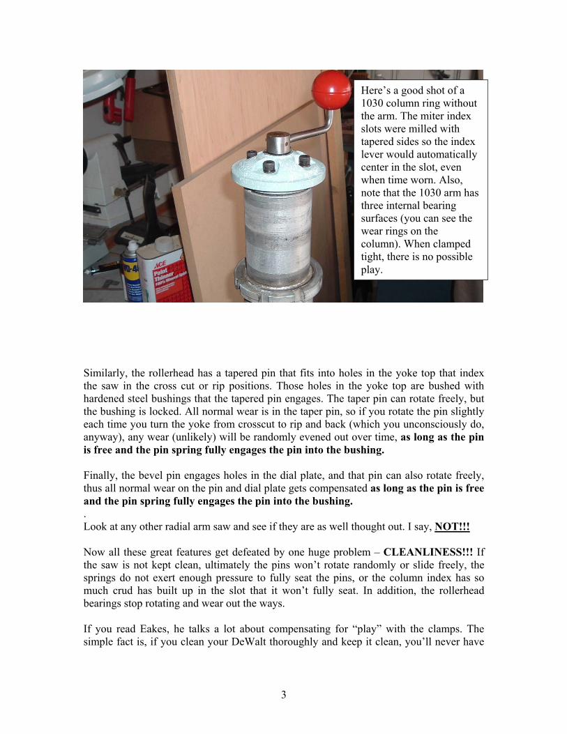
Here’s a good shot of a 1030 column ring without the arm. The miter index slots were milled with tapered sides so the index lever would automatically center in the slot, even when time worn. Also, note that the 1030 arm has three internal bearing surfaces (you can see the wear rings on the column). When clamped tight, there is no possible play.
Finally, the bevel pin engages holes in the dial plate, and that pin can also rotate freely, thus all normal wear on the pin and dial plate gets compensated as long as the pin is free and the pin spring fully engages the pin into the bushing. . Look at any other radial arm saw and see if they are as well thought out. I say, NOT!!! Now all these great features get defeated by one huge problem – CLEANLINESS!!! If the saw is not kept clean, ultimately the pins won’t rotate randomly or slide freely, the springs do not exert enough pressure to fully seat the pins, or the column index has so much crud has built up in the slot that it won’t fully seat. In addition, the rollerhead bearings stop rotating and wear out the ways. If you read Eakes, he talks a lot about compensating for “play” with the clamps. The simple fact is, if you clean your DeWalt thoroughly and keep it clean, you’ll never have
3

to worry about compensating for play – the DeWalt saw is intentionally designed to stay in adjustment, as long as you keep it clean and don’t abuse it!!! THE HOW AND WHY O.K. lets say that you have completely restored, or intend to restore, an old DeWalt. You’ve built, or intend to build a new Mr. Sawdust table, all the bolts are tight, and you are now ready to adjust the saw. Do not install your sacrificial table top at this time. What’s the first thing you should do to get started? Well, before you start, go buy or borrow a dial gage kit with a magnetic base holder (there’s a good one on www.littlemachineshop.com for only $17.95) and a Master Plate (Forrest or Lee Valley Tools) or other machined flat plate. Also get a 6”x 8” or so steel plate. The Master Plate is a little pricey, but it has many more uses besides adjusting an RAS. Now let’s begin.
Here are some of what you will need. The dial gage kit is from the reference. I got the Master Plate from Forrest. I use these with all my tools. They really work well on the jointer, table saw and drill press, as well as the RAS.
COLUMN Adjustment Before you mount the new table, you need to adjust the column so that it has no play, but will crank up and down smoothly and easily. The acme thread elevating screw and the bearing surfaces inside the column base that the column rides on need to be lubricated. Any good axle grease will do, but not too much. The side of the column key that the brass gib bears against should also be lightly greased. It’s the brass gib that keeps the column
4

from rotating in it’s base. The column bearings keep the column from “wiggling” up and down or sideways.
Clamp bolt Set screw Spreader set screw The 1531 column has two clamp bolts and two set screws to hold the brass gib against the column key to eliminate right/left movement. Set screw Clamp bolt
You will want to take out as much play in the elevating crank as you can. Crank play can be minimized by adding shim washers below and above the thrust cap, which is the column cap just below the crank. It has the miter scale attached to it, and mounts to the column with either two or four machine screws with lock washers. I recommend that you replace the original machine screws with socket head cap screws, which are much easier to remove than the original slot head screws, and are a lot stronger. The idea is to add shims, mostly above the cap, just below the crank, so that you eliminate as much free play as possible. Shims can be obtained from McMaster-Carr. The bottom bearing surface on the crank needs to contact the top shim precisely when the crank set screw (or split pin, or taper pin on some DeWalts) is tight in place.
5

Then adjust the column base clamp screws so that the column is held firmly by the bearing surfaces inside the base, and with the miter lock for the arm tight, there is no up/down play in the end of the arm. IMPORTANT! The DeWalt frames do have a bit of flex. Mr. Sawdust points out that there is some frame flex on later DeWalts that can be cured with diagonal straps riveted to opposite frame corners. To eliminate all flex in the base, bolt the frame solidly down to a solid sheet of plywood or MDF, or even better, to a cabinet top or solid wood frame. The DeWalt legs, cabinets and other steel frames are not designed to eliminate flex in the frame, in fact they actually add to it because those are the one part of a DeWalt that were never really well thought out and engineered. Try elevating the column. If it’s too tight, adjust the base clamp screws very slightly until you can raise and lower the arm with a firm cranking pressure. Then tighten the one (or two, on some DeWalts) set screw(s) (which I recommend you replace with cup point socket head cap screws) that force the brass gib against the side of the column key so that when the miter lock for the arm is tight, there is no left/right play in the end of the arm when you try to move it. If this makes raising and lowering too hard, reduce the pressure against the gib by slightly loosening the set screws holding the gib against the column key and tightening the spreader set screw. These adjustments are easy to make, but I have found that most DeWalt arms are way too easy to raise and lower, which produces up and down and/or side play in the arm end. (Note: At the time I took these photos I had run out of 5/16” Socket Head set screws, so the 1531 currently has regular Allen head set screws on the column.) Why? The reason that you need to do this first is that all of the other adjustments depend upon this one being done first. ROLLERHEAD BEARINGS Adjustment The very next adjustment, before any other but the column is to set the rollerhead bearings. The only way to get these perfect is by trial and error. First, I assume you have either new ones or free turning, clean original bearings (no “bumps and grinds”). I also highly recommend that you get two ¼-20 x 5/8” brass point socket head cap screws (available at McMaster-Carr) and replace the ¼”-20 with 5/8” long ¼”-20 socket head set screws that lock the adjustable (right side as you face the saw) bearing shafts. The bearings need to be tight enough so that you can’t stop them from turning with your finger when you move the rollerhead back and forth, AND, more importantly, it should take 4 to 6 pounds of pull to move the rollerhead. Get them right and tight, and after they are perfect, screw in those new brass point socket head set screws to lock the shafts permanently. The chances are you’ll never have to do this again if it’s right the first time.
6
Why? If the bearings are too loose, there will be side “wiggle” play between the bearings and ways, which will not only screw up whatever adjustments you make, it will allow up and down and side play in the rollerhead. Also, the bearings will eventually get cruddy and not rotate, but will slide in the ways, and the saw will move too freely back and forth. The uplift force created by cutting can easily pull the saw both forward and upward and jam the wood, stopping the blade and overheating the motor, or worse, ejecting the wood with great force (chances are great it could hit you and cause harm). This will also wear out the ways faster than anything else. If the bearings are too tight, you will need to exert too strong a force to pull and return the saw. When properly adjusted, the saw can not move up and down or swing left to right or side to side, and it should take 4 to 6 pounds of force to pull or push the saw, so get the bearings perfect and forget them from now on. TABLE Adjustment For this adjustment, I assume you have built a nice, straight, flat Mr. Sawdust table. If you haven’t, do it NOW. First, make sure the table is very securely fastened to the side (and center for the bigger saws) cleats, or, on older saws, to the table mounting rails. The bolts holding the cleats or rails to the frame don’t need to be tight, but the bolts securing the table to the cleats or rails absolutely do. With side cleats, I like to use brass inserts in the table bottom and ¼”-20 Grade 8 bolts, lock washers and flat washers to fasten the table to them, along with 4 new Grade 8 bolts, nuts and lockwashers to fasten the cleats to the sides of the saw frame. You can also drill the table, counterbore the holes and use recessed screws or bolts through the top. If you have a pre-1962 saw, the table needs to be bored to take the hardware that will fasten it to the mounting rails (2 rails on the smaller saws, 3 on 1030s and GWs). I always replace all the table hardware. I use 5/16” socket head screws for the through and fastening bolts, and 5/16” set screws for the flush mounted jack bolts. I also like to use jam nuts instead of regular nuts for jacking and locking the screws, along with flat and lock washers on the MBFs, 925s, GWIs and 1030s with the rails.
7

These cleats are not original. I made them. Note the Grade 8 Mounting bolt, nut, lock & flat washer, and the ¼”-20 x ¾” hex head cap screws mounting the table top to the cleat. These too are Grade 8. Also, note that the MDF Mr. Sawdust table is sprayed with polyurethane to seal it. Lacquer also works fine for this. The MDF soaks up quite a bit, so use several coats if you make your table out of MDF.
To get the table perfectly parallel with the ways, I use a magnetic base and a dial gage mounted on the bottom of the motor. I slightly loosen the miter lock, just enough so I can move the arm left and right, and I raise the miter index lever so the indexer is clear of the slots in the column index. Move the saw so that the dial gage pin is right over the center of one of the side cleats (or rails, as the case may be) as close to the front of the table as you can get it. Loosen all cleat mounting bolts a bit (so you can jack the table freely up or down) except right under the dial gage, where you should tighten the mounting nut. Clamp the miter lock clamp tight. Read the dial gage and note the reading. Make sure the cleat mounting nut (or the rail fastening nut) under the gage is tight.
8
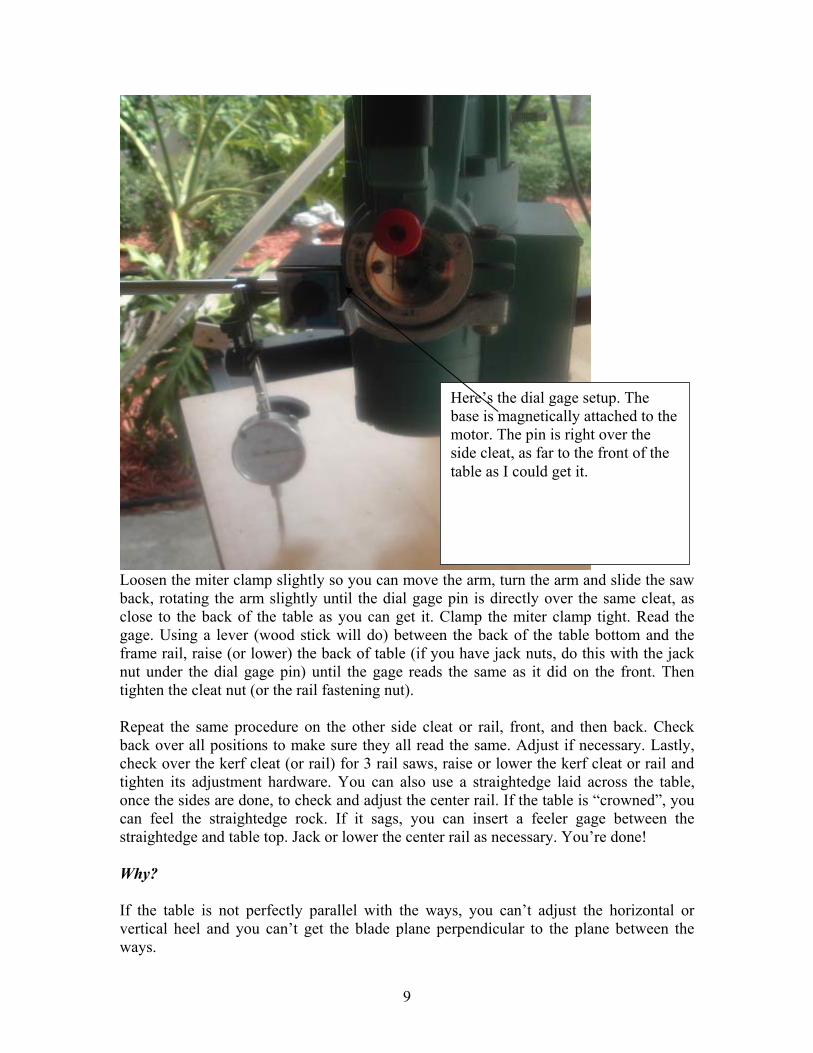
Here’s the dial gage setup. The base is magnetically attached to the motor. The pin is right over the side cleat, as far to the front of the table as I could get it.
Loosen the miter clamp slightly so you can move the arm, turn the arm and slide the saw back, rotating the arm slightly until the dial gage pin is directly over the same cleat, as close to the back of the table as you can get it. Clamp the miter clamp tight. Read the gage. Using a lever (wood stick will do) between the back of the table bottom and the frame rail, raise (or lower) the back of table (if you have jack nuts, do this with the jack nut under the dial gage pin) until the gage reads the same as it did on the front. Then tighten the cleat nut (or the rail fastening nut). Repeat the same procedure on the other side cleat or rail, front, and then back. Check back over all positions to make sure they all read the same. Adjust if necessary. Lastly, check over the kerf cleat (or rail) for 3 rail saws, raise or lower the kerf cleat or rail and tighten its adjustment hardware. You can also use a straightedge laid across the table, once the sides are done, to check and adjust the center rail. If the table is “crowned”, you can feel the straightedge rock. If it sags, you can insert a feeler gage between the straightedge and table top. Jack or lower the center rail as necessary. You’re done! Why? If the table is not perfectly parallel with the ways, you can’t adjust the horizontal or vertical heel and you can’t get the blade plane perpendicular to the plane between the ways.
9

HORIZONTAL HEEL Adjustment Mount a Master Plate (or other perfectly ground flat plate) on the saw arbor shaft. Loosen the front bevel clamp and pivot the saw so the plate is more or less parallel with the table top with the bevel index pin set. Leave the bevel clamp loose. I use the other steel plate on the table top as a base attach the mag base to (that’s why it doesn’t need to be perfectly flat), and I mount the dial gage so the pin hits the bottom side of the Master plate just clear of the arbor collar. Slide the saw until the pin is at the center of the Master Plate just above the center of the mounting collar, and read the gage. Then pull the saw forward until the pin is just on the edge of the rear of the Master Plate. Read the gage. If the readings are not the same, loosen the right and left trunnion set screws and lock nuts no more than 1/6 turn. Then loosen the bottom trunnion set screw and lock nut. I highly recommend replacing the two upper trunnion set screws with cup point socket head set screws, and the bottom trunnion set screw with a flat point socket head set screw. These will not break when tightened or loosened, and the flat point allows the trunnion to slide freely left and right without rotation.
Here’s the setup for horizontal heel. The pin is riding on the underside of the Master Plate. The base is magnetically attached to a steel bar clamped down to the table top. You really don't need a big steel plate for this, just enough to be solid and to clamp down.
As you turn the bottom set screw, the dial gage will register the change. Do not loosen (or tighten) more than 1/6 turn without then loosening (or tightening) the left and right screws 1/6 turn. Adjust the bottom set screw until the dial gage reads the same as it did
1
under the middle of the plate. Push the saw back, check at the center and then push the saw back until the pin is at the front edge of the Master Plate. It should be the same reading. You can usually get this within 0.001” or better without a lot of effort. Tighten the left and right screws and recheck everything. Adjust as necessary until you get it right. Clamp the bevel clamp and check the dial gage readings again. Adjust again if necessary. The dial gage needs to be near perfect (no change between the readings) when the bevel clamp is locked. When done, the trunnion axis of the motor will be perfectly horizontally parallel with the ways (and the table!). Why? The trunnion axis needs to be horizontally parallel with the table BEFORE you can adjust the vertical heel. If it isn’t, and you adjust either the vertical heel or the blade perpendicular to the table, these adjustments will change when you adjust the horizontal heel and will have to be redone anyway.
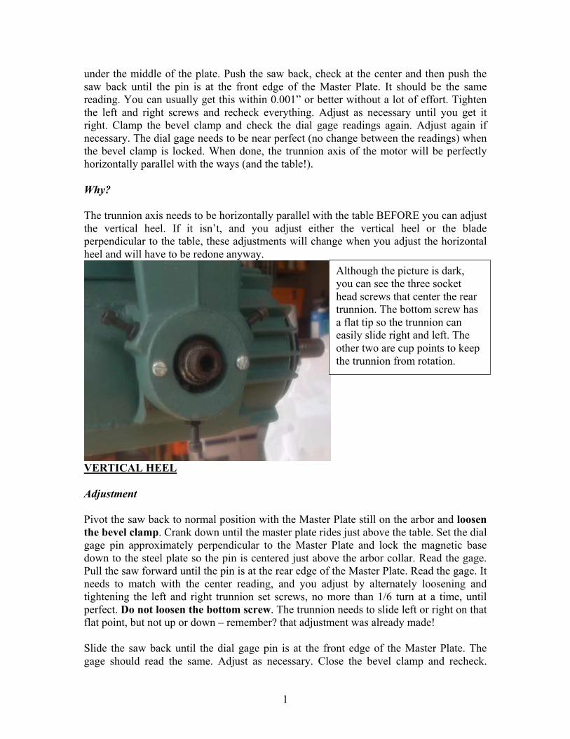
Although the picture is dark, you can see the three socket head screws that center the rear trunnion. The bottom screw has a flat tip so the trunnion can easily slide right and left. The other two are cup points to keep the trunnion from rotation.
VERTICAL HEEL Adjustment Pivot the saw back to normal position with the Master Plate still on the arbor and loosen the bevel clamp. Crank down until the master plate rides just above the table. Set the dial gage pin approximately perpendicular to the Master Plate and lock the magnetic base down to the steel plate so the pin is centered just above the arbor collar. Read the gage. Pull the saw forward until the pin is at the rear edge of the Master Plate. Read the gage. It needs to match with the center reading, and you adjust by alternately loosening and tightening the left and right trunnion set screws, no more than 1/6 turn at a time, until perfect. Do not loosen the bottom screw. The trunnion needs to slide left or right on that flat point, but not up or down – remember? that adjustment was already made! Slide the saw back until the dial gage pin is at the front edge of the Master Plate. The gage should read the same. Adjust as necessary. Close the bevel clamp and recheck.
1

Adjust again if required. Now the trunnion axis is parallel with the centerline between the ways in both horizontal and vertical planes, AND with the table! Best of all, there is no heel present.
This is the vertical heel setup. The pin rides on the side of the Master Plate. A similar setup, but with the Master Plate swung 90 and the gage mounted a lot higher is used to check blade perpendicular to table adjustment.
Why? Taking out the heel makes the saw cut perfect with no tendency to kick back or score the sides of a crosscut or rip. It also prolongs bit life greatly. BLADE PERPENDICULAR TO THE TABLE Adjustment Put the steel plate to the left of the kerf and mount the dial gage horizontal so the pin contacts the Master Plate. Tighten all clamps. Raise the saw until the dial gage pin is close to the bottom edge of the Master Plate. Read the gage. Lower the saw until the dial gage pin is near the top edge of the plate. The dial gage should read the same. It won’t, in most cases. To adjust, take the front logo plate (inside the bevel gage) off the saw and loosen the bevel clamp. This uncovers three socket head set screws in a line. The middle one is centered on the trunnion axis and holds the dial plate to the saw. The ones on each side, if loosened, will allow the saw to rotate without the dial plate rotating with it, in other words, they allow relationship of the bevel index to the saw to be changed.
1
Loosen the two outer cap screws. This should allow you to bevel the saw slightly without loosening the bevel index pin. That’s the whole idea – to change the index location slightly until when the index pin is fully depressed into the dial plate index hole, and the bevel clamp is locked, the blade will be exactly perpendicular to the table. Sometimes you might need to slightly loosen the center cap screw a tiny bit to allow rotation, as the dial plate is frequently frozen against the side of the motor, and it needs to be free to make this adjustment. This is not an easy adjustment. I often use a Starrett square to set the perpendicularity initially, and the check it with the dial gage. Retightening the outer set screws can upset the adjustment and unless you are very lucky, you will need to reset several times before you get it perfect. Also, closing the bevel clamp can throw it off. The whole objective is to set the index so that when the index pin bottoms into the dial plate, and the bevel clamp is locked, the blade will be perfectly perpendicular to the table. Why? This is what assures that your cut ends will be square – the whole purpose of woodworking. We’re almost done. Just one more adjustment and we will be set for a very long time. ARM WAYS PERPENDICULAR TO FENCE Adjustment Install your sacrificial table top and your back table parts and fence, and tighten the two back table clamp screws. Start with a good square against the fence with its blade projecting outward. Crank the arm down so the long side of the Master Plate is just clear of the table. Loosen the arm clamp. Take out the two ¼”-20 set screws that are locking the threads of the arm index adjusting screws. Loosen the arm index adjusting screws. At this point, your option, I recommend removal of the brass slugs between the ends of the set screws and the index adjusting screws, and replacement of the set screws with brass point socket head set screws. Raise the arm index lever, grease the sides of the lever where the adjusting screws bear, and rotate the arm until the Master Plate is square to the fence using your good square. Tighten the arm clamp so the arm is locked “square”. Turn the index lever back down so it seats fully in the index ring. Carefully tighten the two index adjusting screws against the sides of the index lever, a little at a time until tight. Loosen the arm locking lever. Check for square with your good square. You should be close. Alternately loosen and tighten the two index adjusting screws until the arm is “square”. Make sure the index lever is fully seated into the index ring as you adjust the screws. After this is complete, it should be rather difficult to raise and lower the index
1

lever, in other words, the index lever adjusting screws need to be tight against the sides of the lever. Now, take off the Master Plate and install your blade and the guard. Pull the saw out to the front all the way. Raise the blade so it is 3/8” above your new, unkerfed, sacrificial table top. Get a scrap piece of ¾” MDF that is about 12” wide by 16” long, with both long sides dead parallel. Put it against the fence, centered on the saw blade. Start the saw and push it back through the MDF and the fence. It will cut 3/8” into the MDF. Shut off the saw, but don’t move the MDF yet. Make two pencil marks on the table top just below, and on each side of the kerf. Flip the MDF so that what was the front edge is now against the fence, and the saw kerf is against the table top. Slide the MDF left or right until the sides of the kerf are on the marks. Start the saw and cross cut the MDF. Return the saw all the way to the back and shut it off. Pick up either half of the MDF and look at the cut side. If the arm is perfectly perpendicular, the ridge between the upper and lower cuts will be even width along it’s entire length. Any deviation from that will show – wider on one end that the other. Adjust the arm as before until it cuts perfect 90 . Lock in the brass point set screws. Now you can test all cuts. Cut a nice new kerf in your sacrificial table top and try a few cuts. You will be amazed at how great the saw cuts now.
If two is company and three is a crowd, what do you call 5?
1