the hydrometric station - whycos portal (@ wmo ... : the hydrometric station introduction 1. natural...
TRANSCRIPT
Module 1 : Hydrometry
4th- 9th December 20062iE / Groupe EIER-ETSHER,
Project Regional Center
IRD - Unité OBHI (Observatoires Hydrologiques et Ingénierie)
1st part : The hydrometric station
WMO / OMM
Volta-HYCOS Project

1st part : The hydrometric station
Introduction
1. Natural river beds
2. Hydrometric station
3. Station file
4. Acquisition, recording and transmission of hydrological data

• Hydrometry : methology and techniques for water level and flow measurements in rivers
• Hydrometric station : Cross section of a river bed where the following are measured:– Free water surface level:h (m)– Flow of the river: Q (l/s or m3/s)
• Difficulty in continuous flow measurement (technology exists but it’s expensive – eg ultrasonic flow meters)
Continuous water level measurements
Flow measurements to determine rating curves at station Q=f(h)
Introduction
• Principal geometric characteristics• The River bed, a dynamic and evolving
system• River bed’s roughness
1. Natural river beds

1. Natural river bed
The geometry of the river bed : the plan
Dentritic bed:Channels and islandsRiver has high slope and high sediment content(Mountaneous region)
Meandering bed:Sinusoïdal channelRiver has mild slope(Alluvial plain)

1. Natural river bed
Major and minor beds
minor bed
major bed

The geometry of the river bed: longitudinal profile
1. Natural river bed
Principal characteristics :•Slope of the bed : I•Water surface slope : J
Staff gaugeFree water surface

The geometry of the river bed: the cross section
1. Natural river bed
Principal characteristics :•Flow area : A•Wetted perimeter : p•Hydraulic radius: R = A/p
Free water surface

1. Natural river bed
•Lateral movement of channel (erosion of the banks)•Changes in longitudinal and cross section(siltation / scouring)
Example : changes in the Allier river channel (France)
Present river channel
Channel in 1946
The River bed, a dynamic and evolving system in space and time

1. Natural river bed
Ex2 : Effect of siltation on the rating curve of a station during recession
Ex 1 : Effect of scouringon the rating curve of a station during recession
Rating curve Limnigraph
Rating curve Limnigraph

1. Natural river bed
Variations in morphology of river bed can be caused by man :
Changes in sediment equilibrium
Consequences on the morphology of the river (Ex : Incision of the bed)
•Sand winning•Channelisation•Construction of dams•…
Changes in the rating curve at a station
The river bed, a dynamic and evolving system in space and time

1. Natural river bed
Sandy river bed : Bittou station(river Nohao, Nakambe basin, Burkina)
Rocky river bed : Kara station(river Kara, Oti basin, Togo)
River bed’s roughness

1. Natural river bed
20 à 100.050 à 0.100Natural river bed with vegetation
330.030Clean and rough natural river bed
500.020Clean and smooth natural river bed
n State of river bed
Manning’s formula (uniform flow):Q = A*V = A*(R2/3 * S1/2 * 1/n)
•A : Flow area •R : Hydraulic radius•S : Water surface slope (approximatively equal to slope of river bed in uniform flow)
n : Coefficient of ManningK = 1/n
River bed’s roughness

• Principles of operation(conditions of hydraulic controls)
• Criteria of d’implantation
2. The hydrometric station
Boromo station (Mouhoun, Burkina)
• The flow in a river section is said to be under the influence of a control when the flow depends only on the water level at a section (provided the geometry of the channel does not change)
• 2 types of controls: – Channel control (uniform flow)– Section control (critical flow)
2. The hydrometric station
Principles of operation(conditions of hydraulic controls)

2. The hydrometric station
Channel control (uniform flow) :
•Hydraulic and geometric conditions :•Regular channel reach•Flow sufficient to occupy the main channel•Slope sufficient to ensure a good transition of flow
•Under these conditions there exists uniform flow:•The flow characterisitcs are the same from one section to the other (same flow area, same water level, same velocity, …)•The slope of the water surface is about the same as the slope of the river bed

Channel control (uniform flow):
•Under these conditions, the flow is given by the Manning’s formula:
Q = A*V = A*(R2/3 * S1/2 * 1/n)
R : hydraulic radiusS : Water surface slope (approximatively equal to slope of river bed in uniform flow)1/n : Manning’s coefficient
2. The hydrometric station

K=1/n (Manning’s coefficient)V : Velocity S : SlopeR : Hydraulic radius
Monogram to calculate V
Section control (critical flow)
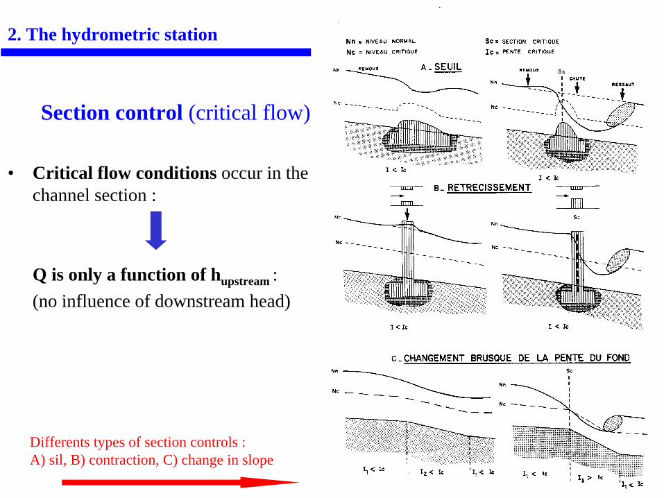
• Critical flow conditions occur in the channel section :
Q is only a function of hupstream : (no influence of downstream head)
2. The hydrometric station
Differents types of section controls : A) sil, B) contraction, C) change in slope
2. The hydrometric station
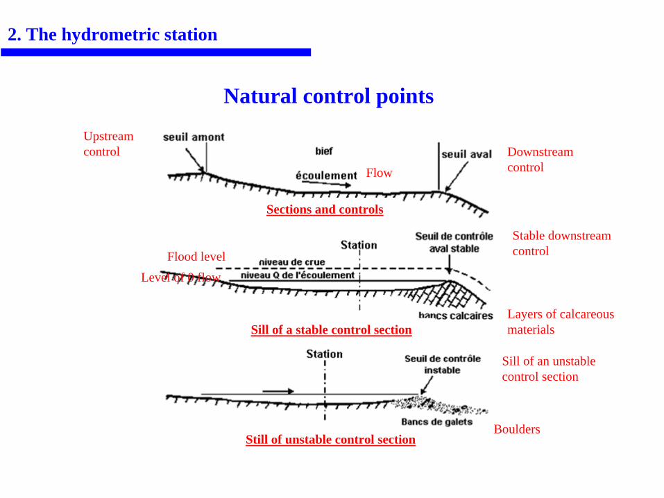
Natural control points
Boulders
Sill of an unstable control section
Sill of a stable control sectionLayers of calcareous materials
Level of 0 flowFlood level
Stable downstream control
Sections and controls
Upstream control
FlowDownstream control
Still of unstable control section

Artificial control structures (weirs)
2. The hydrometric station
1 : Submerged weir
2 : Unsubmerged weir1 & 2: Free Fall : the weir works

Hydraulic control
Summary:
•A flow in a channel reach is under hydraulic control when for each flow there are corresponding well defined hydraulic characteristics, in particular same water level
•The control can be localised at a section or occur in a channel reach (Channel- Control);
•The main quality attribute of a control is its permanence:In spaceIn time (stability of geometric and hydraulic characteristics)
2. The hydrometric station
Instability of the control Rating curve becomes invalid

2. The hydrometric station
ACCESSIBILITY TO SITESTABILITY OF THE BED (BOTTOM AND BANKS)HIGH SENSIVITYSTRAIGHT CHANNEL REACHSTABLE CONTROLSTATION ACCOMODATES ALL FLOW FROM THE CATCHMENTFAVORABLE LOCATIONS FOR INSTALLING STAFF GAUGESFLOW MEASUREMENT SECTION ACCESSIBLE IN FLOODS AND NOT TOO FAR
Criteria for installation of hydrometric stations: choice of site
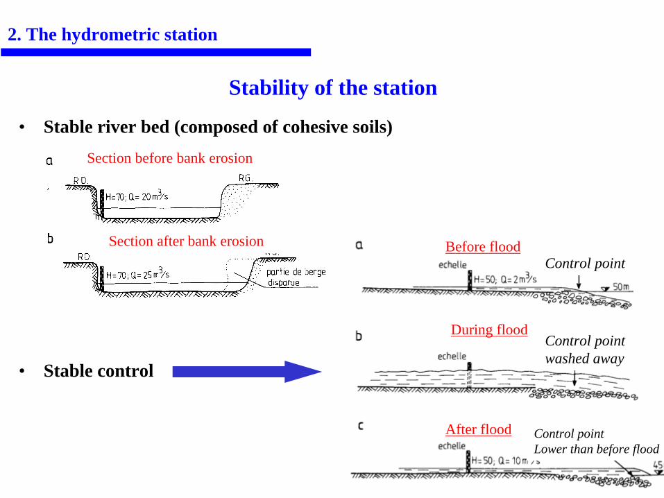
• Stable river bed (composed of cohesive soils)
• Stable control
Stability of the station
2. The hydrometric station
Before flood
During flood
After flood
Control point
Control point washed away
Control point Lower than before flood
Section before bank erosion
Section after bank erosion
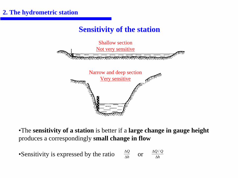
Sensitivity of the station
2. The hydrometric station
•The sensitivity of a station is better if a large change in gauge height produces a correspondingly small change in flow
•Sensitivity is expressed by the ratio or ΔΔ
Qh
ΔΔQ Q
h/
Shallow sectionNot very sensitive
Narrow and deep sectionVery sensitive

3. Station file
It consists of the following elements:
•Description of the station (name, code, coordinates, …)•Objectives of the station •Equipment installed at the station •Topographic survey of the station
•Longitudinal profile•Cross sectional profile•Staff gauges attached to a benchmark
•Management of the station•Reports of station visits •History of repair works•Changes in gauge reader, …
•Rating curves and flow measurements carried out•…
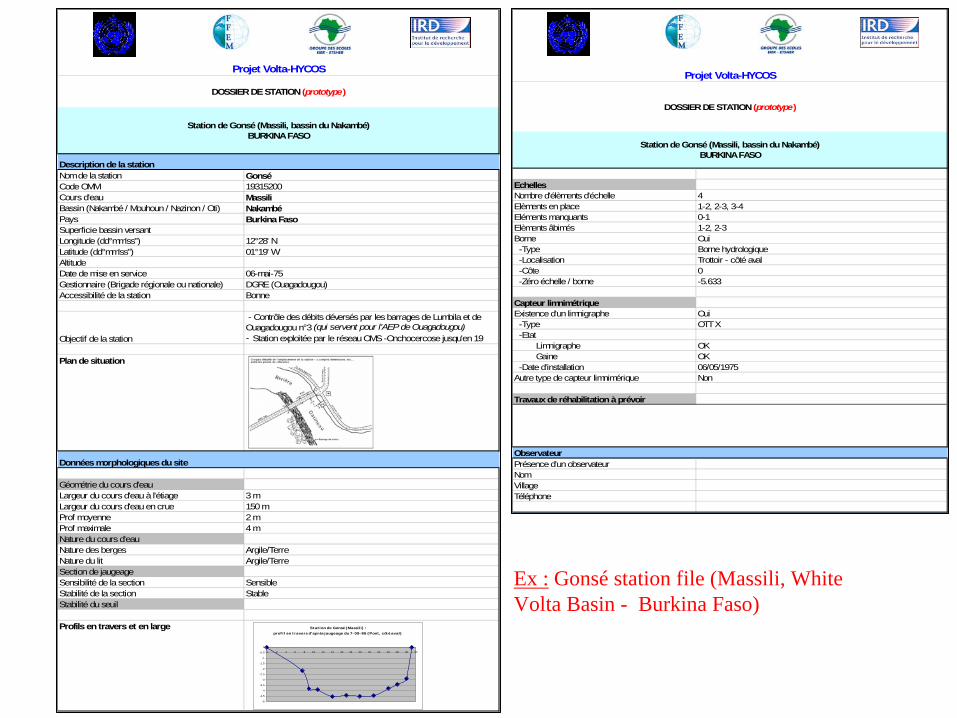
Description de la stationNom de la station GonséCode OMM 19315200Cours d'eau MassiliBassin (Nakambé / Mouhoun / Nazinon / Oti) NakambéPays Burkina FasoSuperficie bassin versantLongitude (dd°mm'ss") 12°28' NLatitude (dd°mm'ss") 01°19' WAltitudeDate de mise en service 06-mai-75Gestionnaire (Brigade régionale ou nationale) DGRE (Ouagadougou)Accessibilité de la station Bonne
Objectif de la station
- Contrôle des débits déversés par les barrages de Lumbila et de Ouagadougou n°3 (qui servent pour l'AEP de Ouagadougou) - Station exploitée par le réseau OMS -Onchocercose jusqu'en 19
Plan de situation
Données morphologiques du site
Géométrie du cours d'eauLargeur du cours d'eau à l'étiage 3 mLargeur du cours d'eau en crue 150 mProf moyenne 2 mProf maximale 4 mNature du cours d'eauNature des berges Argile/TerreNature du lit Argile/TerreSection de jaugeageSensibilité de la section SensibleStabilité de la section StableStabilité du seuil
Profils en travers et en large
Projet Volta-HYCOS
DOSSIER DE STATION (prototype)
Station de Gonsé (Massili, bassin du Nakambé) BURKINA FASO
St at ion de Gonsé (Massili) : prof il en t ravers d'après jaugeage du 7- 09- 86 ( Pont , côt é aval)
-5
-4.5
-4
-3.5
-3
-2.5
-2
-1.5
-1
-0.5
0
0 2 4 6 8 10 12 14 16 18 20 22 24 26 28 30 32
EchellesNombre d'élèments d'échelle 4Elèments en place 1-2, 2-3, 3-4Eléments manquants 0-1Elèments âbimés 1-2, 2-3Borne Oui -Type Borne hydrologique -Localisation Trottoir - côté aval -Côte 0 -Zéro échelle / borne -5.633
Capteur limnimétrique Existence d'un limnigraphe Oui -Type OTT X -Etat Limnigraphe OK Gaine OK -Date d'installation 06/05/1975Autre type de capteur limnimérique Non
Travaux de réhabilitation à prévoir
ObservateurPrésence d'un observateurNomVillageTéléphone
Projet Volta-HYCOS
DOSSIER DE STATION (prototype)
Station de Gonsé (Massili, bassin du Nakambé) BURKINA FASO
Ex : Gonsé station file (Massili, White Volta Basin - Burkina Faso)

Module 1 : hydrometry
IRD - Unité OBHI (Observatoires Hydrologiques et Ingénierie)
Acquisition, recording and transmission of hydrological data
WMO / OMM
Projet Volta-HYCOS
1st part : The hydrometric station
4th- 9th December 20062iE / Groupe EIER-ETSHER,
Project Regional Center

Acquisition, recording and transmission of hydrological data
1. Hydrometric sensors2. Data acquisition and recording3. Transmission of hydrologic data4. Flow measurements

Staff Gauges:
• These are installed along a section of the river• One gauge starts where the other ends• They are referenced to a TBM or a survey pillar
1. Water level measurement
• Float devices– Automatic water level recorder (chart)– Eletronic shaft encoder (ex : Thalimedes from OTT)
• Pressure sensors– Hydrostatic pressure sensors– Sensors based on the bubble in principle
• Ultra-sonic sensors• Radar sensors
Different Types of Water Level recorders
1. Water level sensors
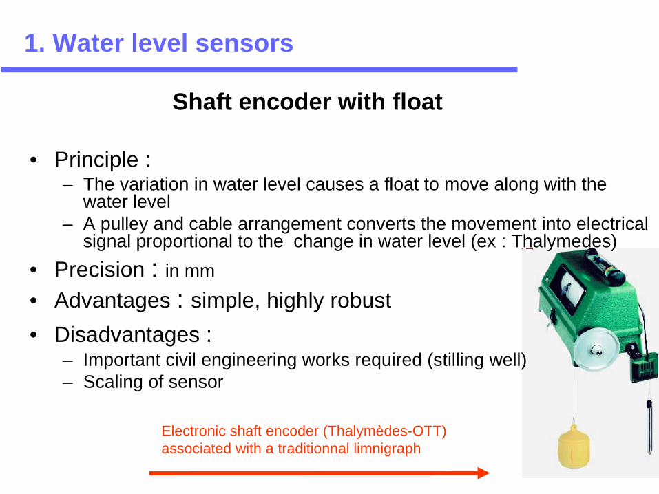
• Principle :– The variation in water level causes a float to move along with the
water level– A pulley and cable arrangement converts the movement into electrical
signal proportional to the change in water level (ex : Thalymedes)• Precision : in mm
• Advantages : simple, highly robust• Disadvantages :
– Important civil engineering works required (stilling well)– Scaling of sensor
Shaft encoder with float
Electronic shaft encoder (Thalymèdes-OTT) associated with a traditionnal limnigraph
1. Water level sensors

Shaft encoder with float
1. Water level sensors

Daboya Station (White Volta, Ghana)
1. Water level sensors

Bittou Station (Nohao, Burkina)

• Principle: measures the hydrostatic pressure of a column of water– Deformation of a membrane under the effect of hydrostatic
pressure– Transformation of the deformation mechanical into electric
signal by a pressure transducer– Transducers more frequently used: ceramic
• Precision : from 0.5 mm to 1 cm depending upon the range of measurement
Hydrostatic pressure sensors
1. Water level sensors
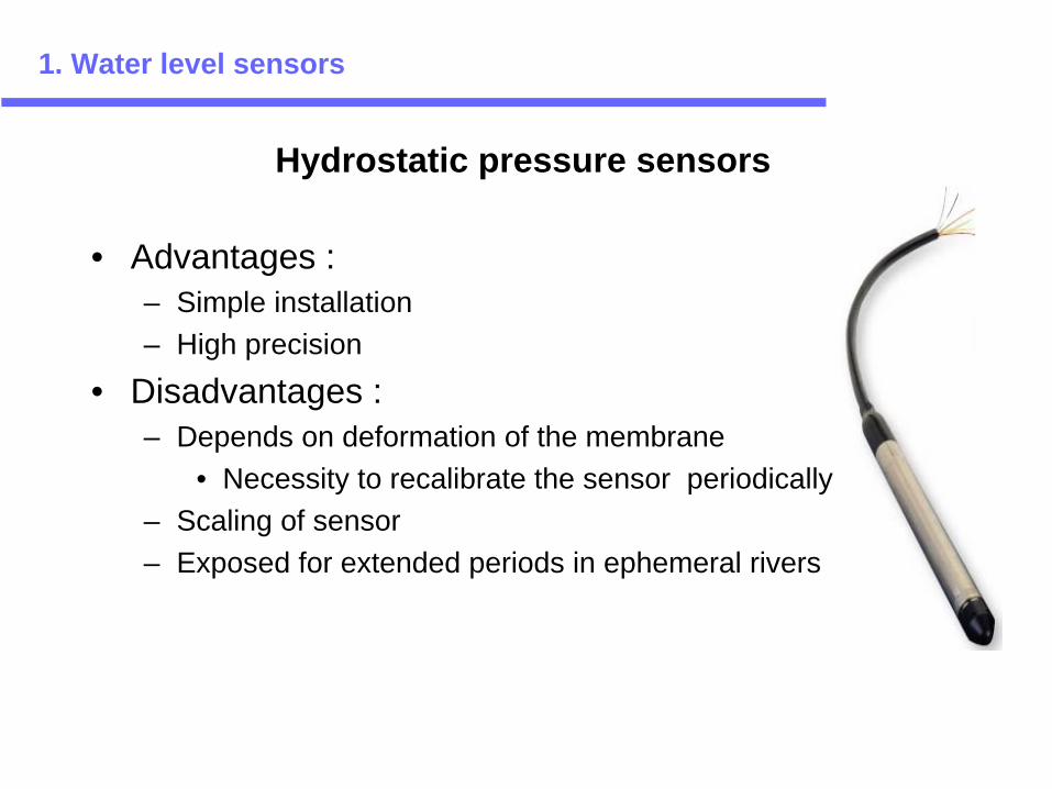
• Advantages : – Simple installation – High precision
• Disadvantages : – Depends on deformation of the membrane
• Necessity to recalibrate the sensor periodically– Scaling of sensor– Exposed for extended periods in ephemeral rivers
Hydrostatic pressure sensors
1. Water level sensors

• Principle :– Compressor sends a bubble in an immersed tube– The resultant pressure is proportional to the water level
above the sensor• Precision: from 0.5 mm to 1 cm depending upon the range of
measurement• Avantages :
– Simple installation– Good sensitivity (1 cm for 10 m)
• Disadvantages : – Heavy maintenance required– Difficult to measure in turbulent flows
1. Water level sensors
Sensor based on bubble-in principle
• Principle: – Measures the time of travel of a signal which is emitted from the sensor,
reflected and detected by the sensor again.
– Water level (h) is deduced from the time of propagation of the wave by the water as h = c*T/2 where c of the signal in air and T the time required for the signal to return
• 2 types:– Immersed sensors– Air borne sensors
• Advantages:– Can be used to measure flows with high concentration of sediments (Air
borne sensors)• Disadvantages:
– Factors that influence the readings are difficult to take into account (T°, salinity, wind, …) : necessary to smoothen and recalibrate the values
1. Water level sensors
Ultra-sonic sensors

1. Water level sensors
Hydrometric sensors : summary
Precision Influence by fatigue
Robustness Installation Cost
Shaft encoder with float
A few mm no Robust Tidious and cosly (civil engineering works)
~600 €
Hydrostatic pressure sensors
A few mm yes Sensitive to scaling and exposure (ephemeral rivers)
Simple 500 € –4000 €
Bubble in sensors
A few mm yes Sensitive to scaling Simple ~1000 €
Ultra-sonic sensors
A few mm no Simple > 10 000 €
Radar sensors
A few mm no 1500 €

2. Data acquisition and recording
• Data logger : – Memory for data storage– Programming of sensors :
• For data recording at predetermined time intervals• For data recording as a function of water level
• Number of sensors connected• Memory : up to several Mb (several months of autonomy)• Independent or integrated to sensor
Infra Red linkage
Connection to sensors
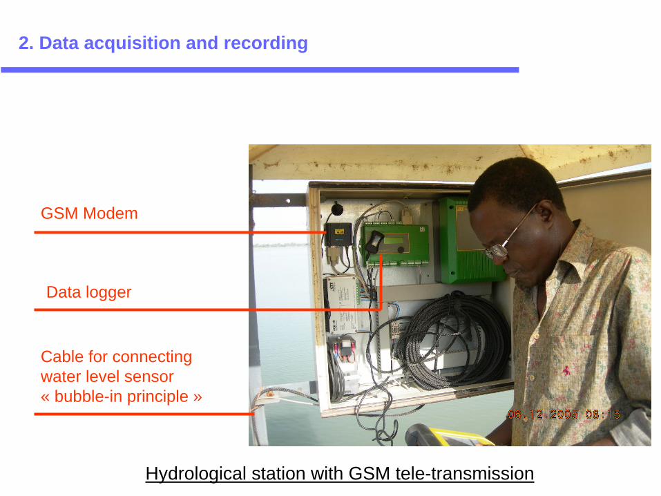
GSM Modem
Data logger
Cable for connecting water level sensor« bubble-in principle »
Hydrological station with GSM tele-transmission
2. Data acquisition and recording

• Objective:– Real time (flood fore casting, management of
water systems in real time, …)– In quasi-real time for the day to day management
or surveillance of hydrometric network • Different systems of data transmission:
– Telephone: Line telephone/GSM– Satellite– Radio
3. Hydrological data transmission
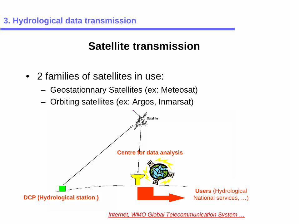
• 2 families of satellites in use:– Geostationnary Satellites (ex: Meteosat) – Orbiting satellites (ex: Argos, Inmarsat)
3. Hydrological data transmission
Satellite transmission
DCP (Hydrological station )
Internet, WMO Global Telecommunication System …
Centre for data analysis
Users (Hydrological National services, …)
• Frequency of emission can be changed• Alarm channel• Centre for data Analysis:
European Spatial Agency (ESA) Germanywww.eumetsat.de
• Free Annual subscription in the framework of WMO WHYCOS programme
3. Hydrological data transmission
Meteosat transmission

3. Hydrological data transmission
Meteosat transmetter
Power supply and antenna

• Sends out data every 200 second• Reception is a function of the visibility of the emitter
to the satellites• 2 centers for data analysis:
– CLS (Toulouse, France)– Argos Services Inc. (Landover, USA)
• Annual subscription: ~1000 Euros/perstation (for one transmission per day)
3. Hydrological data transmission
Argos transmission system
HydroArgos transmetter

• Data logger equiped with a modem and a SIM card• Data mode or SMS mode• 2 communication ports for data mode:
– User calls the data logger– The data logger calls the user (can be programmed for alarm)
3. Hydrological data transmission
GSM transmission

• WHO-Onchocerciasis (Argos)• HydroNiger Hydrological network (Argos)• Flood warning system for Bagre dam
(Inmarsat satellite)• …. Volta-HYCOS Stations (Meteosat)
3. Hydrological data transmission
Some examples of tele-transmission in the sub-region

4. Flow measurements
• Different techniques of flow measurement: – Flow measurements with current meter– Flow measurements using ultra-sonic sensors– ADCP– …
• Flow measurements with current meter:
Current meter C31 (OTT) Flow measurements by wading
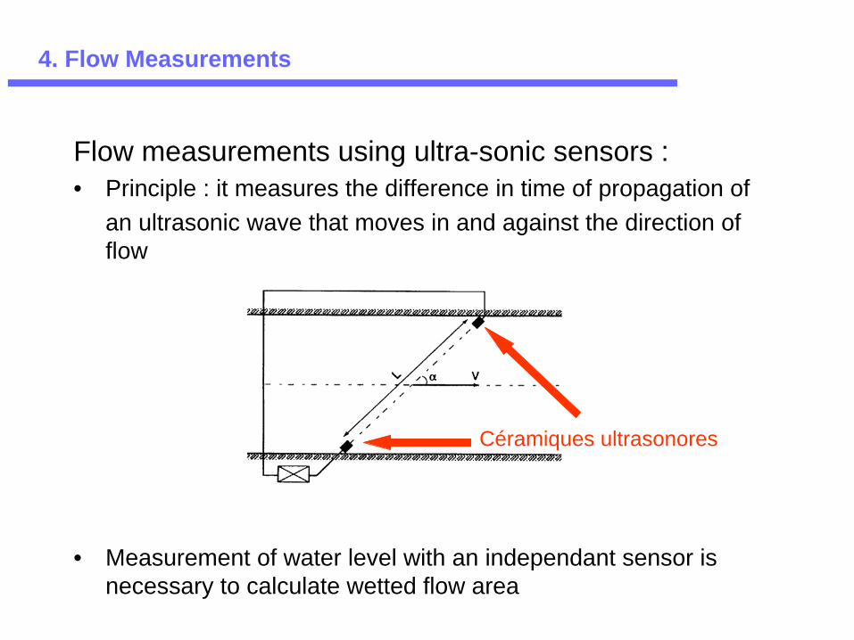
Flow measurements using ultra-sonic sensors :• Principle : it measures the difference in time of propagation of
an ultrasonic wave that moves in and against the direction of flow
• Measurement of water level with an independant sensor is necessary to calculate wetted flow area
Céramiques ultrasonores
4. Flow Measurements

• Conditions for use :– Straight channel reach– Flow less loaded (sediment, vegetation, bubbles,…cause
attenuation of acoustic signal– Stability of river bed (determination of the wetted area with
the help of cross section)– Price : about 15 000 Euros
4. Flow Measurements
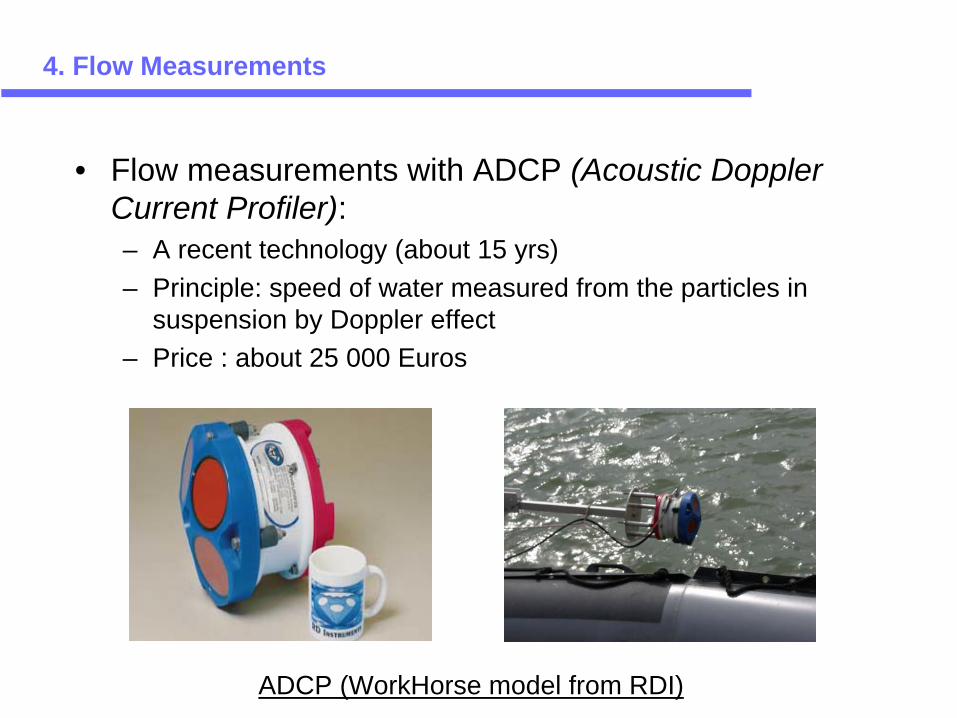
• Flow measurements with ADCP (Acoustic Doppler Current Profiler):– A recent technology (about 15 yrs) – Principle: speed of water measured from the particles in
suspension by Doppler effect– Price : about 25 000 Euros
4. Flow Measurements
ADCP (WorkHorse model from RDI)
Transducer
Acousticpulse
Magnified viewof scatterers
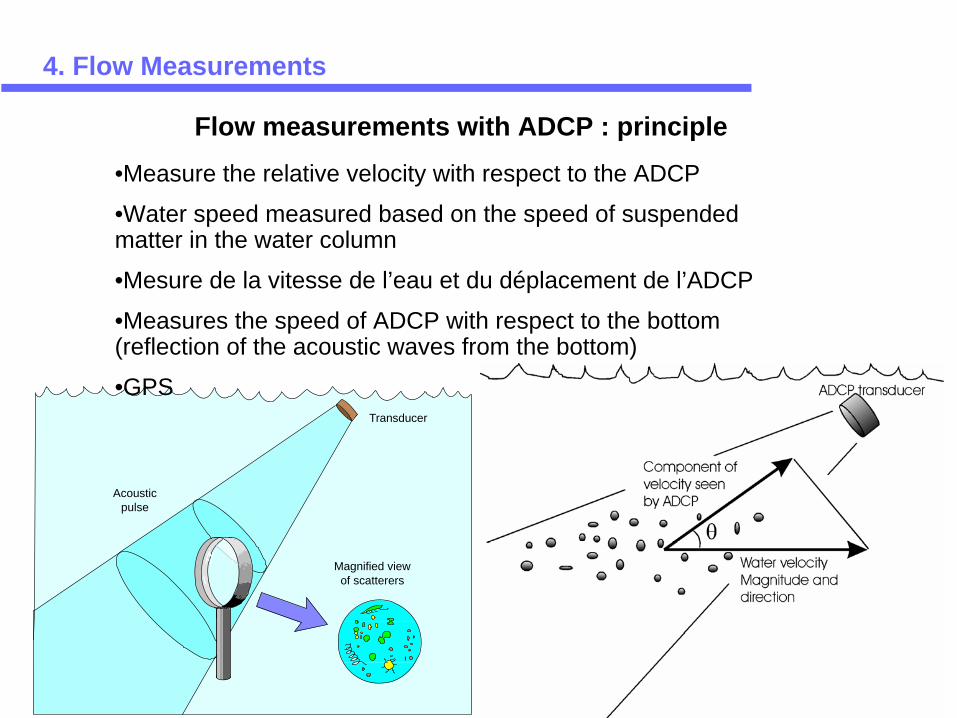
Flow measurements with ADCP : principle
•Measure the relative velocity with respect to the ADCP
•Water speed measured based on the speed of suspended matter in the water column
•Mesure de la vitesse de l’eau et du déplacement de l’ADCP
•Measures the speed of ADCP with respect to the bottom (reflection of the acoustic waves from the bottom)
•GPS
4. Flow Measurements
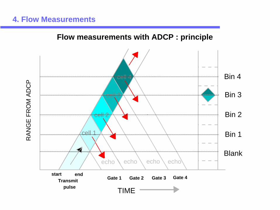
cell 1
cell 2
cell 3
cell 4
echo echo echo echo
Transmitpulse
start endGate 1 Gate 2 Gate 3 Gate 4
TIME
Blank
Bin 1
Bin 2
Bin 3
Bin 4
RAN
GE
FRO
M A
DC
P4. Flow Measurements
Flow measurements with ADCP : principle

Some Internet links…
• Hydrometry :– http://wwwrcamnl.wr.usgs.gov/sws/SWTraining/FlashFandR/Index.html : a
good on-line training course on the l’USGS ‘U.S. Geological Survey’ internet site– http://www.usobhi.net : IRD-OBHI internet site– http://hydram.epfl.ch/e-drologie/ Ecole Polytechnique Fédérale de Lausane (EPFL)– http://www.enpc.fr/cereve/HomePages/gaume/courshydro/courshydro.html#4
(E.N.Pont et Chaussées-CEREVE)
• Some manufacturers of hydrological equipment (on the Net…) :– OTT (German)– SEBA (German)– Eijkelkamp– Sutron (USA)– RD Instruments (ADCP) – …