the hyper-code abstraction - computer science web archive
TRANSCRIPT

Towards Simplification of the Software Development Process The Hyper-Code Abstraction
Evangelos T. Zirintsis
Thesis submitted for the Ph.D. degree St Andrews August, 2000
School of Computer Science, University of St Andrews St Andrews, Fife KY16 9SS, Scotland
I
Acknowledgements
Neither this thesis nor my academic upbringing would have
materialised without the sharp supervisory eye and tireless
commitment of Ron Morrison.
The completion of this thesis would have never been achieved
without the insightful comments of Graham Kirby, whose role
has been pivotal.
My warmest thanks and deepest gratitude goes to my parents,
whose support both financial and moral has made all this
possible.
Finally, I would also like to thank all those who intentionally
or unintentionally have shaped the strength of my character.
Their positive and negative comments kept me going
throughout this demanding process.
II
Abstract
Following Aristotle's theory of substances and accidents, the difficulties
in developing software can be categorised into essences and accidents.
Essences are the conceptual constructs that compose an abstract software
entity. Accidents are representations of these abstract entities in
programming environments, which quite often constitute noise in the
process of developing software.
The focus of this thesis is on improving the software life-cycle, by
introducing a new set of abstract concepts — hyper-code — that allows
the accidents of the traditional programming life-cycle to be lessened. The
hyper-code view of programming still contains accidental difficulties, but
these are fewer and more understandable. A plethora of concepts, which
exist only for reasons of efficiency, are hidden from the programmer, by
the hyper-code system thereby producing a simpler system. The main
hypothesis of the thesis is that this reduction in complexity increases
programmer productivity.
A concrete implementation of the hyper-code concepts is a Hyper-Code
System. This thesis reports on the design of the system using two
particular programming languages (ProcessBase and PJama), and on the
implementation of the user interface in PJama.
III
Contents 1 Introduction.................................................................................1
1.1 Essences and Accidents ............................................................................1 1.2 Levels of Abstraction................................................................................2 1.3 Thesis Structure ........................................................................................4
2 Related Work ..............................................................................6 2.1 Traditional Programming Life Cycle........................................................6 2.2 Software Development Environments ......................................................7
2.2.1 EMACS.............................................................................................8 2.2.2 Metrowerks CodeWarrior.................................................................9 2.2.3 Visual Basic ....................................................................................11 2.2.4 Smalltalk .........................................................................................12 2.2.5 Trellis ..............................................................................................14 2.2.6 Integrated Project Support Environments (IPSEs) .........................15
2.2.6.1 IPSE 2.5........................................................................................... 16 2.2.6.2 ECLIPSE IPSE................................................................................. 17 2.2.6.3 APSE ............................................................................................... 17
2.2.7 Persistent Programming — Napier88.............................................17 2.2.8 Hyper-Programming in Napier88 and PJama.................................20
2.3 Towards Hyper-Code..............................................................................23 2.4 Summary.................................................................................................24
3 The Hyper-Code Abstraction — Towards Hyper-Code Systems.............................................................................................26
3.1 The Hyper-Code View of the Programming Life-Cycle ........................26 3.1.1 Defining the Domains.....................................................................26 3.1.2 Domain Operations.........................................................................27 3.1.3 Composing Domain Operations – Equivalences ............................28 3.1.4 Interpretations of the Domain Operations ......................................29 3.1.5 Towards Concrete Systems.............................................................29
3.2 Hyper-Code Systems ..............................................................................30 3.2.1 General Requirements for the Hyper-Code Operations..................30 3.2.2 A Particular Set of HCOs ...............................................................30 3.2.3 Accessing Data in a Persistent HCS ...............................................32
3.3 Summary.................................................................................................33
4 Concrete Hyper-Code System ..................................................34 4.1 The Hyper-Code Representation ............................................................34 4.2 A Particular Set of Hyper-Code Operations ...........................................35
4.2.1 Explode ...........................................................................................35 4.2.2 Implode ...........................................................................................36 4.2.3 Evaluate ..........................................................................................36
4.2.3.1 Viewing the Evaluation .................................................................... 36 4.2.3.2 Result of Evaluation ......................................................................... 38

IV
4.2.4 GetRoot...........................................................................................38 4.2.5 Edit..................................................................................................38
4.3 Summary.................................................................................................40
5 A Hyper-Code System for ProcessBase ...................................41 5.1 Domains in ProcessBase.........................................................................41 5.2 Equivalences in ProcessBase Hyper-Code .............................................42 5.3 Operations Over HCRs ...........................................................................43
5.3.1 Explode ...........................................................................................43 5.3.2 Implode ...........................................................................................45 5.3.3 Evaluate ..........................................................................................45
5.3.3.1 Viewing the Evaluation .................................................................... 45 5.3.3.2 Result of Evaluation ......................................................................... 47
5.3.4 Get Root..........................................................................................48 5.3.5 Edit..................................................................................................48
5.4 Summary.................................................................................................50
6 A Hyper-Code System for PJama ............................................51 6.1 Domains in PJama ..................................................................................51 6.2 Equivalences in PJama ...........................................................................52 6.3 Operations Over HCRs ...........................................................................52
6.3.1 Explode ...........................................................................................53 6.3.2 Implode ...........................................................................................54 6.3.3 Evaluate ..........................................................................................54
6.3.3.1 Viewing the Evaluation .................................................................... 54 6.3.3.2 Result of Evaluation ......................................................................... 56
6.3.4 Get Root..........................................................................................57 6.3.5 Edit..................................................................................................57
6.4 Summary.................................................................................................58
7 Implementing Hyper-Code in PJama ......................................59 7.1 Representing HCRs ................................................................................59 7.2 Implementation of the Evaluation Process .............................................60
7.2.1 The Storage Form ...........................................................................61 7.2.2 Transforming an HCR into a Class Definition ...............................64 7.2.3 The Textual Form ...........................................................................65 7.2.4 Inserting Code for Variable Tracking.............................................67
7.2.4.1 Requirements for the Inserted Code.................................................. 68 7.2.4.2 Meeting the Requirements - The Thread of Execution ...................... 68 7.2.4.3 Transforming the Example HCR ...................................................... 70 7.2.4.4 Transforming an Example HCR Representing a Class Definition...... 71
7.2.5 Compiling and Executing HCRs ....................................................72 7.2.5.1 Compiling and Loading Class Definitions......................................... 72 7.2.5.2 Executing Methods........................................................................... 72 7.2.5.3 Compiling and Executing the Example HCR .................................... 74
7.2.6 Producing a new HCR ....................................................................74 7.3 Summary.................................................................................................74

V
8 Implementing the Hyper-Code Assistant Tool in PJama .......76 8.1 The Basic Editor .....................................................................................76 8.2 The Window Editor ................................................................................78 8.3 The Hyper-Code User Editor..................................................................79 8.4 The Explode Operation...........................................................................81
8.4.1 Generating an HCR for a Primitive Type .......................................81 8.4.2 Generating an HCR for an Array Type...........................................81 8.4.3 Generating an HCR for a Class or Interface...................................82 8.4.4 Generating an HCR for a Primitive Value......................................82 8.4.5 Generating an HCR for an Array....................................................82 8.4.6 Generating an HCR for a Class Instance ........................................83 8.4.7 Displaying the Generated HCR ......................................................85
8.5 Summary.................................................................................................85
9 Conclusions................................................................................86 9.1 Simplification at the Abstract Level .......................................................86 9.2 Simplification at the Concrete Level ......................................................86 9.3 Hyper-Code Systems and Related Work ................................................87 9.4 Current Design and Implementation Status............................................87 9.5 General Discussion of HCSs ..................................................................88
9.5.1 Choosing the Particular HCR .........................................................88 9.5.2 Choosing the Particular Set of HCOs .............................................89 9.5.3 Mapping Hyper-Code Into Particular Languages...........................89
9.5.3.1 Hyper-Linking ................................................................................. 89 9.5.3.2 Generating Detailed HCRs for Entities ............................................. 90 9.5.3.3 Information Hiding........................................................................... 91 9.5.3.4 Mutable Locations............................................................................ 91 9.5.3.5 Openness.......................................................................................... 92 9.5.3.6 Persistence and Referential Integrity................................................. 92 9.5.3.7 Compatibility ................................................................................... 93
9.5.4 Essential and Desirable Features for Hyper-Code..........................93 9.6 Further Research Work...........................................................................94 9.7 Final Thoughts ........................................................................................94
10 Appendix ................................................................................96 10.1 Index of Tables .......................................................................................96 10.2 Index of Figures......................................................................................97
11 References ..............................................................................99

1
1 Introduction 1.1 Essences and Accidents According to Aristotle, the Greek philosopher, there is a distinction between the way reality is structured and the way it is viewed. The basic logical distinction is between substance and accident [Ros28].
A substance is whatever is a natural kind of thing and exists in its own right. An accident is the modification that a substance undergoes but does not change the kind of thing that each substance is. This distinction is logical and reflects the structure of reality. Substances may exist without accidents but an accident must always be associated with a substance.
Following Aristotle's theory of substances and accidents, [Bro86] categorises the difficulties in software technology into essences and accidents. According to Brooks
Essences are the complex conceptual structures that compose an abstract software entity. The essence of a software entity is a construct of interlocking concepts: data sets, relationships among data items, algorithms, and invocations of functions. Accidents are the representations of these abstract entities in programming languages and the mapping of these onto machine languages within space and speed constraints.
Therefore, an essence is the problem itself and is an amalgamation of data and algorithms. Accidents are the problems arising from using tools to solve the original problem. These may be hardware constraints, limitations by awkward programming languages and such like. The hardest part in building software is to specify, design and test the conceptual construct (essences), and not to represent and test its fidelity (accidents). Nevertheless, most work on software engineering has concentrated on solving problems caused by accidental difficulties. Removing unnecessary complexity, that is the accidental difficulties, produces a simpler system. This presents to the programmer either fewer or more understandable concepts and forms. The main hypothesis is that a simpler system is better for developing software, as it increases programmer productivity. The work to be described is based on the belief that the gap between essence and accident is still with us. It is also believed that the specification of the appropriate abstract concepts result in fewer accidents, and this allows the essences to be viewed more appropriately. Using the Aristotelian terminology, this implies that a better view of the reality is provided. The focus of the thesis is on improving the software life cycle. This is achieved by introducing a new set of abstract concepts — hyper-code —that allow accidents of

2
the traditional programming life-cycle to be lessened. As will be explained later in detail, the hyper-code view of the programming life cycle still contains accidental difficulties, but these are fewer and more understandable. A plethora of concepts, which exist only for reasons of efficiency, such as interchange forms and tools, are hidden from the programmer.
1.2 Levels of Abstraction The task of programming may be viewed at different levels of abstraction, as shown in Figure 1. Programming may be performed at any level, depending on the problem to be solved. There is a trade off between efficiency and programmer convenience when moving from one layer to another. A view of a system at the lower layer is closer to what a machine may execute, which makes programming more flexible and efficient. A view of a system at a higher layer is perceived to have improved productivity in terms of programmer understandability compared to a view at a lower layer. Language designers try to balance making computing convenient for people with making efficient use of computing machines. However, according to [Set96] convenience comes first. Without it, efficiency is irrelevant.
Modern OperatingSystems such as Unix
Assembler
High-LevelProgrammingEnvironments
Modern ProgrammingEnvironment Level
DatabaseProgrammingEnvironments
Machine efficiency flexibility
convenience
Machine Level
Operating SystemLevel
Figure 1: Programming at different levels of abstraction
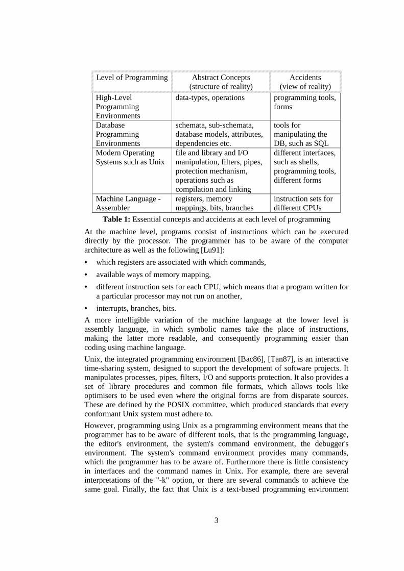
Programming at each level requires manipulation of different abstractions, representations and operations. Some of these concepts are essential for programming at the particular level. The rest exist only for reasons of efficiency, and they are considered accidents as they can be hidden either by specifying new abstract concepts or by providing different tools. Typical abstract concepts and the accidents for each layer of the programming life-cycle are shown in Table 1.
3
Level of Programming Abstract Concepts (structure of reality)
Accidents (view of reality)
High-Level Programming Environments
data-types, operations programming tools, forms
Database Programming Environments
schemata, sub-schemata, database models, attributes, dependencies etc.
tools for manipulating the DB, such as SQL
Modern Operating Systems such as Unix
file and library and I/O manipulation, filters, pipes, protection mechanism, operations such as compilation and linking
different interfaces, such as shells, programming tools, different forms
Machine Language - Assembler
registers, memory mappings, bits, branches
instruction sets for different CPUs
Table 1: Essential concepts and accidents at each level of programming At the machine level, programs consist of instructions which can be executed directly by the processor. The programmer has to be aware of the computer architecture as well as the following [Lu91]: • which registers are associated with which commands, • available ways of memory mapping, • different instruction sets for each CPU, which means that a program written for
a particular processor may not run on another, • interrupts, branches, bits. A more intelligible variation of the machine language at the lower level is assembly language, in which symbolic names take the place of instructions, making the latter more readable, and consequently programming easier than coding using machine language. Unix, the integrated programming environment [Bac86], [Tan87], is an interactive time-sharing system, designed to support the development of software projects. It manipulates processes, pipes, filters, I/O and supports protection. It also provides a set of library procedures and common file formats, which allows tools like optimisers to be used even where the original forms are from disparate sources. These are defined by the POSIX committee, which produced standards that every conformant Unix system must adhere to. However, programming using Unix as a programming environment means that the programmer has to be aware of different tools, that is the programming language, the editor's environment, the system's command environment, the debugger's environment. The system's command environment provides many commands, which the programmer has to be aware of. Furthermore there is little consistency in interfaces and the command names in Unix. For example, there are several interpretations of the "-k" option, or there are several commands to achieve the same goal. Finally, the fact that Unix is a text-based programming environment
4
may be considered a drawback in programming. GUI-based operating systems, such as Mac-OS [App86], [Nai93] and Windows [Mic98+] are designed to make such programming easier. A solution to the complexity of operating systems as programming environments is to make them "invisible" by building a collection of tools on top. Examples of such collections are database environments and high-level integrated programming environments. The principle, in terms of programming, is that these environments hide the operating system, as the programmer can concentrate on the accidental difficulties of the higher-level, rather than on the accidental difficulties of the operating system level. In database environments, such as MSAccess [Dow98], [Mic94] and dBase [And99], the programmer is required to be aware of the basic principles of databases. This involves building the logical schema and possible sub-schemata in order to develop the desired application. Other concepts involved in this task are: database models, attributes and dependencies, normalisation, etc [Tsi77], [Ull80]. The accidental difficulties in these environments are caused by the programmer having to be aware of the tools, such as SQL [CB98], [Dat93] that manipulate a database. In high-level, integrated programming environments, such as Turbo Pascal [Bor89], reality is structured in terms of abstract constructs, such as operations and data-types. The programmer is required to be aware of accidents such as tools and forms, rather than concepts that the underlying system is responsible for, such as device drivers, processes etc. Object-oriented languages provide a different structure of the essence by introducing concepts such as classes, instances, methods and subclasses. The way of thinking is at the application level, in terms of objects and interactions needed to describe the application [Set96]. However, the programmer is still aware of operations, data-types and tools. The main observation of the description above is that each view of abstraction removes the accidental difficulties of the view below it, by hiding or improving the understandability of the concepts of that view. According to the assumption introduced in section 1.1, this produces a simpler system, that increases the programmer productivity. The hyper-code view introduces different abstract concepts, in order to address the accidental difficulties of the traditional software development life-cycle, which is followed by most of the systems described above. This results in presenting the programmer with fewer accidents, and thus - according to the original assumption - in increasing programmer productivity.
1.3 Thesis Structure Chapter 2 provides a survey of the related work in this area involving the description of several programming environments, which attempt to simplify the traditional programming life-cycle. Persistence and hyper-programming are also involved in achieving this goal.
5
Chapter 3 describes the hyper-code view of programming, which simplifies the traditional programming life-cycle. A set of abstract concepts provides a different structure of the essence. These are then mapped into a more concrete level to produce a set of concrete operations, which are performed in Hyper-Code Systems, that is programming systems which implement the ideas of hyper-code. Chapter 4 defines the concrete operations with respect to particular interpretations of the underlying domain operations. This definition is combined with an illustration of how the user interface looks for each of the concrete operations. Chapters 5 and 6 map the description given in chapter 4 into two particular languages: a simple persistent language, ProcessBase [MBG+99b], and a persistent object oriented language, PJama [AJ96]. Chapters 7 and 8 describe the principal features of the implementation of a hyper-code system in PJama. Chapter 9 concludes this thesis by reviewing the hyper-code level of programming. In addition to that, a conclusion is drawn related to mapping a hyper-code system into a programming language. Researching the design and the implementation of a hyper-code system in two particular languages indicated that mapping is possible, but is not always satisfactory. Finally, future work in this area involves further improvements of the current implementation in PJama, and the mapping onto the ProcessBase language.

6
2 Related Work This chapter describes the traditional programming life-cycle and outlines programming environments that attempt to address the accidental difficulties of it.
2.1 Traditional Programming Life Cycle In programming environments that follow the traditional life-cycle, such as Pascal [Wir71], the programmer concentrates on abstract constructs, such as operations, data-types, and accidents such as forms and tools, rather than concepts that the underlying system is responsible for, such as bits, registers, branches, device drivers, processes etc. In these environments, software is developed following the traditional compose-compile-link-execute cycle illustrated in Figure 2.
pre-processing compilation linkage
execution
debugging
pre-processor compiler object code linker
execution engine
debugger
start
text
process tool conceptual form interchange form
composition
stream
text
file / stream text
keyboard
file
file / stream
object code file / stream
text text
file / stream
data file
stream
stream
text file
editor
denotes optional
stream text
executable code
result
end
Figure 2: The traditional programming life cycle
The programmer composes a program by typing text or inserting text from a file. In some cases, pre-processing is required to prepare the source code for compilation. Compiling this piece of code produces either an error or object code. In the former case the programmer returns to composing, finds the error and recompiles the source. In the latter case, the programmer links explicitly the object code produced by compilation with some external object code from the libraries. If linking is successful, executable code is produced which can be used for either execution or debugging. At this stage run-time errors are possible which means that the programmer may have to restart the cycle from the beginning. Restarting the cycle may also be required if the results from execution are unexpected. Thus, there are five main processes: composition, compilation, linkage and execution or debugging each with their appropriate tools such as editor, compiler, linker, executor or debugger respectively. Each tool operates on a particular translated form of the program such as source text, object code or executable code. Traditional programming systems, such as Pascal [Bor89] and C [KR78] access data in a file system or database as shown in Figure 3. Programs (“program 1” and “program 2”) and their executable versions (“executable code 1” and “executable code 2” respectively) are held outside the database boundary, commonly in a file

7
system. These are prepared independently of the data and include assertions to specify access paths of the data they require. Linking with the data is performed dynamically during program execution at which time a dynamic type check or coercion may take place. As shown in Figure 3, this is done through the dynamically checked access points.
References to dynamically checked access pointsReferences to data in the database
program 1
database boundary
persistent data
dynamically checked access points
access pointspecification program 2
executablecode 1
executablecode 2
Figure 3: Traditional access to long-lived data
In programming environments that follow the traditional life-cycle, complexity comes from the programmer having to be aware of concepts like forms and tools. These often constitute noise in the execution cycle and a distraction from the task of concentrating on the essential difficulties, that is constructing the application.
2.2 Software Development Environments The programming systems described in this section attempt to simplify the traditional software development life-cycle either by just hiding some accidental difficulties or by specifying a new set of abstract concepts that result in different accidents. Each of the systems represents a category of programming environments, as shown in Figure 4.

8
General TextEditors as
ProgrammingEnvironments
Editor-BasedProgrammingEnvironments
Browser-BasedProgrammingEnvironments
PersistentProgrammingEnvironments
Emacs CodeWarrior Smalltalk Trellis Napier88
Hyper-Programmingin Napier88
Hyper-Programmingin PJama
Hyper-Code
Several Programming Environments
VisualProgrammingEnvironments
Visual Basic
IntegratedProjectSupport
Environments
ECLIPSE APSE
Figure 4: Systems that attack accidents of the traditional software life-cycle
The dashed-arrows denote that the system they point to inherits some features from the system above, but still specify some new concepts and features. Note that the box with the black background denotes programming systems that apply the hyper-code ideas, that is Hyper-Code Systems. The description, contained in the rest of this chapter, is focused on whether these systems satisfy certain criteria. These criteria, listed below, are general and involve abstract concepts and accidents. • they hide concepts of the traditional programming life-cycle from the
programmer (Abstraction). • they provide a single representation for both program and data (Unification). • they provide a single tool for all operations (Simplification).
2.2.1 EMACS Emacs is a display editor that supports multiple buffers and windows as well as compiling, debugging, customisations, syntax colouring and such like. It is described as advanced, customisable and extensible [Sta97] since: • it provides facilities that go beyond simple insertion and deletion: automatic
indentation of programs; viewing two or more files at once; editing formatted text; colouring expressions and comments in several programming languages
• it allows the changing of the definitions of commands as well as the rearrangement of the command set.
• it allows the writing of entirely new commands, programs in the Lisp language to be run by Emacs's own Lisp interpreter. Almost any part of Emacs can be replaced [Gli97].
A snapshot of an Emacs window is shown in Figure 5. The window contains two buffers each of which contains a definition of a Java class; the one at the top

9
displays class WindowEditor and the one at the bottom class UserEditor. Syntax colouring allows comments, reserved words and class names to be displayed in a different colour. Emacs is a general editing tool that can be used for programming in any language. Since it provides different buffers, every operation can be performed in the same window, which provides the facility of pre-customising multiple fonts, styles, colours and sizes. Programming in Emacs means that the programmer is aware of all the accidents of the traditional software development cycle. Simplification is achieved by allowing the programmer to specify macros for tools in order to automate the relevant operations. However, the programmer is still aware of the different forms resulting from each operation. Finally, it does not support any browsing facilities.
Figure 5: A snapshot of editing Java programs in Emacs
2.2.2 Metrowerks CodeWarrior The Metrowerks CodeWarrior programming environment [Met99] provides a multi-host, multi-language, and multi-target design that gives engineers the freedom to choose the best path to their goal [TT99]. In the context of the thesis this implies that it reduces the accidental difficulties in order to solve the essential difficulty, which is the problem itself. Indeed, CodeWarrior is designed to accelerate the development process by combining an editor, compiler, linker and debugger into a single application. Source, libraries, graphic resources, and other files are gathered into a project. The usage of a project hides some of the concepts of the traditional programming life-

10
cycle, such as forms. Information about the project is stored in a project file, and is manipulated through the project manager tool.
Figure 6: A snapshot of an example project
A snapshot of an example project in Metrowerks CodeWarrior Java for Windows is shown in Figure 6. This project contains the classes used for the implementation of the Hyper-Code System, which will be described in the following chapters. The buttons on the top-right of the light grey area are used to trigger syntax checking, compilation, linking and execution. The red-tick symbol on the left of the window indicates classes/packages that have to be compiled. Apart from the project manager tool, CodeWarrior provides an editor and a debugging tool. The editor supports multiple faces by colouring the keywords for various high-level programming languages to allow easy recognition and navigation. It can automatically verify the balance of parentheses, brackets and braces. It also integrates source browsing facilities, as every word in the source becomes a link to other locations in the code related to that symbol.
Figure 7: A snapshot of editing and browsing in CodeWarrior Java
Figure 7 shows an example editor window that contains a Java class definition. The HyperLine symbol is considered as a hyper-link, as pressing the mouse button

11
over it results in a menu through which the programmer can browse the source code of the linked class definition. The debugger tool provides source-code level debugging. CodeWarrior requires the programmer to specify explicitly when execution involves debugging, and this achieved by entering the "Debugging" mode. A programmer can set breakpoints and single-step through the editor window. During execution, a separate representation from programs is used in order to browse data, such as variables, arrays, and structures.
2.2.3 Visual Basic Microsoft® Visual Basic [Mic98], as a programming environment, is a fast and easy way to create applications for Microsoft Windows [Mic97]. It allows the creation of databases and front-end applications, using SQL, for most popular database formats [War95]. It provides a set of tools such as composer, browser and debugger. Simplification of the application development is achieved by hiding some of the concepts of the traditional programming life-cycle, such as forms and processes like compilation and linking. However, the programmer has to be aware of newly introduced features, which make up an application, such as modules, projects, forms and control files. The main advantage of the Visual Basic interactive programming environment [Mic96] is that it makes the composition process easier. The programmer may drag and drop pre-built objects into place on screen rather than writing numerous lines of code to describe the appearance and locations of the GUI elements. This is illustrated in Figure 8. The objects to be inserted in the application are contained in the toolbox on the left-hand side. Information about the tools included in the project are positioned on the right-hand side. In the example, the application consists of a frame that contains a combo box and a checkbox.
Figure 8: Composing an application in Visual Basic
The tools are called classes and can be browsed using a separate browsing tool. Each class has a number of properties which are displayed in the browser window (centre) and their values are displayed in properties window as shown in the figure
12
above (right-bottom window). Visual Basic supports hyper-links to allows navigation between classes and properties in the browser window. Source code is generated behind the scenes, which can be edited by the programmer at any time. A facility that makes composition easier is the provision of syntax colouring. In addition, during composition, source code is interpreted, which results in catching and highlighting most syntax or spelling errors on the fly. However, not every error is caught by the system, which requires the programmer to find it, fix it and start the programming cycle over again. In addition, the programmer is aware of two different representations, one for source code and one for data. These are displayed in the editor and the object browser respectively. Another tool provided is a standard, integrated, graphical debugger, which allows source level debugging to be performed. This involves setting breakpoints, monitoring values and such like. The debugging process is performed separately from execution, and this is indicated by the presence of different set of menu items for each process, as shown in Figure 8.
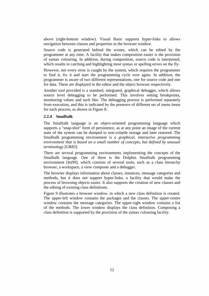
2.2.4 Smalltalk The Smalltalk language is an object-oriented programming language which supports a "snap-shot" form of persistence, as at any point an image of the current state of the system can be dumped to non-volatile storage and later restored. The Smalltalk programming environment is a graphical, interactive programming environment that is based on a small number of concepts, but defined by unusual terminology [GR83]. There are several programming environments implementing the concepts of the Smalltalk language. One of them is the Dolphin Smalltalk programming environment [Int99], which consists of several tools, such as a class hierarchy browser, a workspace, a view composer and a debugger. The browser displays information about classes, instances, message categories and methods, but it does not support hyper-links, a facility that would make the process of browsing objects easier. It also supports the creation of new classes and the editing of existing class definitions. Figure 9 illustrates a browser window, in which a new class definition is created. The upper-left window contains the packages and the classes. The upper-centre window contains the message categories. The upper-right window contains a list of the methods. The lower window displays the class definition. Composing a class definition is supported by the provision of the syntax colouring facility.

13
Figure 9: A snapshot of a Smalltalk browser window displaying a class
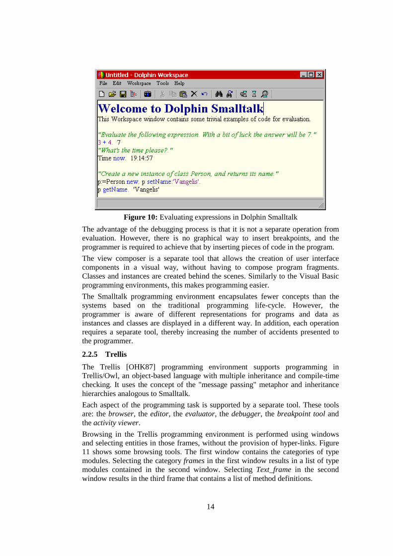
Programs can be composed in the workspace tool. Evaluation is performed over the selected piece of text, and the result (if any) is printed after the selection. The evaluate operation substitutes the compile-link-execute cycle. Figure 10 illustrates a workspace that contains several examples of source code. The last example creates a new instance of class Person, sets the name field and retrieves it using the newly created object. Execution may be interrupted when an error occurs or when a breakpoint is reached, in which case the system informs the programmer about the cause of interruption. This is done by activating the debugger tool, which displays the last messages sent as well as allowing the inspection of the stack and causes the evaluation to proceed from the selected point. Message-sends can be single-stepped, in order to check the state of variables and determine the source of the error.
14
Figure 10: Evaluating expressions in Dolphin Smalltalk
The advantage of the debugging process is that it is not a separate operation from evaluation. However, there is no graphical way to insert breakpoints, and the programmer is required to achieve that by inserting pieces of code in the program. The view composer is a separate tool that allows the creation of user interface components in a visual way, without having to compose program fragments. Classes and instances are created behind the scenes. Similarly to the Visual Basic programming environments, this makes programming easier. The Smalltalk programming environment encapsulates fewer concepts than the systems based on the traditional programming life-cycle. However, the programmer is aware of different representations for programs and data as instances and classes are displayed in a different way. In addition, each operation requires a separate tool, thereby increasing the number of accidents presented to the programmer.
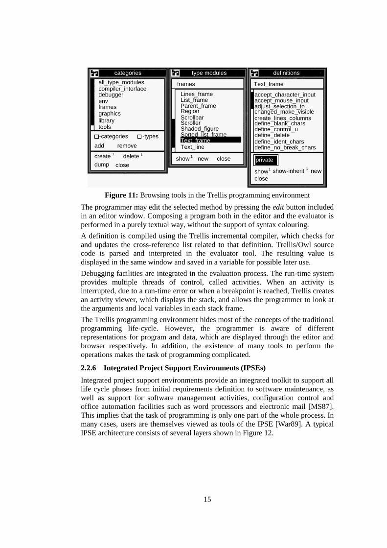
2.2.5 Trellis The Trellis [OHK87] programming environment supports programming in Trellis/Owl, an object-based language with multiple inheritance and compile-time checking. It uses the concept of the "message passing" metaphor and inheritance hierarchies analogous to Smalltalk. Each aspect of the programming task is supported by a separate tool. These tools are: the browser, the editor, the evaluator, the debugger, the breakpoint tool and the activity viewer. Browsing in the Trellis programming environment is performed using windows and selecting entities in those frames, without the provision of hyper-links. Figure 11 shows some browsing tools. The first window contains the categories of type modules. Selecting the category frames in the first window results in a list of type modules contained in the second window. Selecting Text_frame in the second window results in the third frame that contains a list of method definitions.
15
compiler_interfaceall_type_modules
debuggerenvframesgraphicslibrarytools
List_frameLines_frame
Parent_frameRegionScrollbarScrollerShaded_figureSorted_list_frameText_frameText_line
accept_mouse_inputaccept_character_input
adjust_selection_tochanged_make_visiblecreate_lines_columnsdefine_blank_charsdefine_control_udefine_deletedefine_ident_charsdefine_no_break_chars
Text_frameframes
type modules definitions
-categories -typesadd
categories
remove
deletecreatedump close
show new close
show show-inherit newclose
private1 1
11
1
Figure 11: Browsing tools in the Trellis programming environment
The programmer may edit the selected method by pressing the edit button included in an editor window. Composing a program both in the editor and the evaluator is performed in a purely textual way, without the support of syntax colouring. A definition is compiled using the Trellis incremental compiler, which checks for and updates the cross-reference list related to that definition. Trellis/Owl source code is parsed and interpreted in the evaluator tool. The resulting value is displayed in the same window and saved in a variable for possible later use. Debugging facilities are integrated in the evaluation process. The run-time system provides multiple threads of control, called activities. When an activity is interrupted, due to a run-time error or when a breakpoint is reached, Trellis creates an activity viewer, which displays the stack, and allows the programmer to look at the arguments and local variables in each stack frame. The Trellis programming environment hides most of the concepts of the traditional programming life-cycle. However, the programmer is aware of different representations for program and data, which are displayed through the editor and browser respectively. In addition, the existence of many tools to perform the operations makes the task of programming complicated.
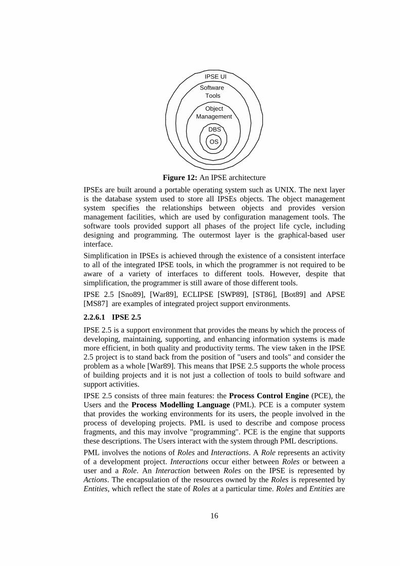
2.2.6 Integrated Project Support Environments (IPSEs) Integrated project support environments provide an integrated toolkit to support all life cycle phases from initial requirements definition to software maintenance, as well as support for software management activities, configuration control and office automation facilities such as word processors and electronic mail [MS87]. This implies that the task of programming is only one part of the whole process. In many cases, users are themselves viewed as tools of the IPSE [War89]. A typical IPSE architecture consists of several layers shown in Figure 12.
16
OS
DBS
ObjectManagement
SoftwareTools
IPSE UI
Figure 12: An IPSE architecture
IPSEs are built around a portable operating system such as UNIX. The next layer is the database system used to store all IPSEs objects. The object management system specifies the relationships between objects and provides version management facilities, which are used by configuration management tools. The software tools provided support all phases of the project life cycle, including designing and programming. The outermost layer is the graphical-based user interface. Simplification in IPSEs is achieved through the existence of a consistent interface to all of the integrated IPSE tools, in which the programmer is not required to be aware of a variety of interfaces to different tools. However, despite that simplification, the programmer is still aware of those different tools. IPSE 2.5 [Sno89], [War89], ECLIPSE [SWP89], [ST86], [Bot89] and APSE [MS87] are examples of integrated project support environments.
2.2.6.1 IPSE 2.5 IPSE 2.5 is a support environment that provides the means by which the process of developing, maintaining, supporting, and enhancing information systems is made more efficient, in both quality and productivity terms. The view taken in the IPSE 2.5 project is to stand back from the position of "users and tools" and consider the problem as a whole [War89]. This means that IPSE 2.5 supports the whole process of building projects and it is not just a collection of tools to build software and support activities. IPSE 2.5 consists of three main features: the Process Control Engine (PCE), the Users and the Process Modelling Language (PML). PCE is a computer system that provides the working environments for its users, the people involved in the process of developing projects. PML is used to describe and compose process fragments, and this may involve "programming". PCE is the engine that supports these descriptions. The Users interact with the system through PML descriptions. PML involves the notions of Roles and Interactions. A Role represents an activity of a development project. Interactions occur either between Roles or between a user and a Role. An Interaction between Roles on the IPSE is represented by Actions. The encapsulation of the resources owned by the Roles is represented by Entities, which reflect the state of Roles at a particular time. Roles and Entities are
17
the principal class in PML and they defined a set of property categories, which include resources, assocs and actions.
2.2.6.2 ECLIPSE IPSE The ECLIPSE IPSE is built on top of existing facilities. The aim of the user interface project was to construct a portable, consistent appropriate interface to a project support environment which improved user's productivity by speeding up system interaction, reducing learning time and reducing user errors [SWP89]. One of the key features of the ECLIPSE environment is that it provides facilities to allow existing tools for programming support to be integrated. The tools available include a design-editing system, host tools to support an Ada system such as compiler, and a design-support system. It supports a graphical user interface with sufficient functionality, involving control panels, a message system and a help system. The end-user interacts with the user interface through the Applications Interface, which is implemented using a description language called FDL (Frame Description Language). Access to the ECLIPSE database is achieved through SySL (System Structure Language).
2.2.6.3 APSE The Ada [You84] IPSE or APSE (Ada Project Support Environment) is a portable environment which consists of the following layers: • System software: supports the host operating system, such as UNIX. • A Kernel APSE (KAPSE): provides database access, tool communications
and run-time support. • A Minimal-APSE (MAPSE): provides the basic toolkit for the development
of Ada systems, including editors, translators, debuggers, linkers, loaders, a command interpreter, a file administrator and a configuration manager.
• An APSE: provides tools such as a program editor, a documentation system, a version control system, a fault report system, a project control system and such like.
2.2.7 Persistent Programming — Napier88 Napier88 [MBC+96b], [MCK+99] is a language that implements the concepts of persistent programming. One of the original motivations for persistent programming was to remove the conceptually unnecessary distinction between short-term and long-term data [ABC+83]. The persistence of a data object is the length of time that the object exists. In traditional programming languages, data cannot last longer than the activation of the program without explicit storage in a file system or a database. In orthogonally persistent programming systems, data can outlive the program, and their persistence obeys the following principles, as described in [AM95]: • The Principle of Persistence Independence: the form of a program is
independent of the longevity of the data that it manipulates. Programs look the same whether they manipulate short-term or long-term data.
18
• The Principle of Data Type Orthogonality: all data objects should be allowed the full range of persistence irrespective of their type. There are no special cases where objects are not allowed to be long-lived or are not allowed to be transient.
• The Principle of Persistence Identification: the choice of how to identify and provide persistent objects is orthogonal to the universe of discourse of the system. The mechanisms for identifying persistent objects is not related to the type system.
The benefits of persistence can be summarised as follows: • Improved program productivity: the provision of persistence removes the
accidental difficulty of writing extra code related to the explicit movement of data between main and backing store. This means that the programmer concentrates more on the essence and the way it is structured rather than on the complexity of the support system.
• The provision of protection mechanisms: the fact that orthogonally persistent systems are strongly typed prevents accidental misuse. In most programming languages, the simplest way to break the protection system is to output a value as one type and input it again as another. In persistent systems it is possible for the type system to extend over lifetime of data.
• The preservation of referential integrity: the referential integrity of an object means that, once a reference to an object in the persistent environment has been established, the object will remain accessible via that reference for as long as the reference exists. It also means that the type correctness of all such references is maintained, and that the identities of the objects are unique.
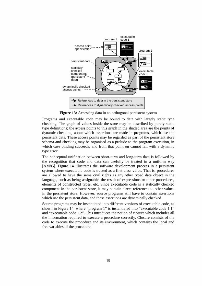
In most persistent programming systems [MCC+95], data are used as illustrated in Figure 13. Programs and executable code are held outside the persistent store, commonly in a file system and they contain, in addition to the access paths of objects, type specifications for those objects. The type specifications are represented in the figure by shaded boxes. The data inside the persistent store is strongly typed and forms a graph of interconnected objects.
19
staticallycheckedcomponents(persistentdata)
program 1
persistent data
dynamically checked access points
access pointspecification program 2
executablecode 1
executablecode 2
References to dynamically checked access pointsReferences to data in the persistent store
Figure 13: Accessing data in an orthogonal persistent system
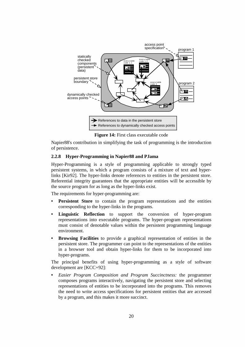
Programs and executable code may be bound to data with largely static type checking. The graph of values inside the store may be described by purely static type definitions; the access points to this graph in the shaded area are the points of dynamic checking, about which assertions are made in programs, which use the persistent data. These access points may be regarded as part of the persistent store schema and checking may be organised as a prelude to the program execution, in which case binding succeeds, and from that point on cannot fail with a dynamic type error. The conceptual unification between short-term and long-term data is followed by the recognition that code and data can usefully be treated in a uniform way [AM85]. Figure 14 illustrates the software development process in a persistent system where executable code is treated as a first class value. That is, procedures are allowed to have the same civil rights as any other typed data object in the language, such as being assignable, the result of expressions or other procedures, elements of constructed types, etc. Since executable code is a statically checked component in the persistent store, it may contain direct references to other values in the persistent store. However, source programs still have to contain assertions which use the persistent data, and these assertions are dynamically checked. Source programs may be instantiated into different versions of executable code, as shown in Figure 14, where “program 1” is instantiated into “executable code 1.1” and “executable code 1.2”. This introduces the notion of closure which includes all the information required to execute a procedure correctly. Closure consists of the code to execute the procedure and its environment, which contains the local and free variables of the procedure.
20
persistent storeboundary
dynamically checked access points
program 1access pointspecification
program 2
execu tablecode 1.2
staticallycheckedcomponents(persistentdata)
execu tablecode 1.1
execu tablecode 2
References to dynamically checked access pointsReferences to data in the persistent store
Figure 14: First class executable code
Napier88's contribution in simplifying the task of programming is the introduction of persistence.
2.2.8 Hyper-Programming in Napier88 and PJama Hyper-Programming is a style of programming applicable to strongly typed persistent systems, in which a program consists of a mixture of text and hyper-links [Kir92]. The hyper-links denote references to entities in the persistent store. Referential integrity guarantees that the appropriate entities will be accessible by the source program for as long as the hyper-links exist. The requirements for hyper-programming are: • Persistent Store to contain the program representations and the entities
corresponding to the hyper-links in the programs. • Linguistic Reflection to support the conversion of hyper-program
representations into executable programs. The hyper-program representations must consist of denotable values within the persistent programming language environment.
• Browsing Facilities to provide a graphical representation of entities in the persistent store. The programmer can point to the representations of the entities in a browser tool and obtain hyper-links for them to be incorporated into hyper-programs.
The principal benefits of using hyper-programming as a style of software development are [KCC+92]: • Easier Program Composition and Program Succinctness: the programmer
composes programs interactively, navigating the persistent store and selecting representations of entities to be incorporated into the programs. This removes the need to write access specifications for persistent entities that are accessed by a program, and this makes it more succinct.

21
• Safety and Early Checking: one of the ways to improve safety is to perform checks earlier than normal, subsequently giving increased assurance of program correctness. This is possible because entities are available for checking before run-time. The way that checking and linking is performed is described later in this section.
• Procedure Representations: hyper-programs can be used to represent executable programs. When a procedure value is created, a hyper-link to its hyper-program representation may be established. This representation may contain hyper-links to other values in the persistent store, including links to shared locations.
• Increased Range of Linking Times: in the hyper-programming system, linking can be performed at any time during the software development process. Deciding when components should be linked into a main program involves trade-offs between program safety, flexibility and execution efficiency, and this is described in detail in [KCC+92].
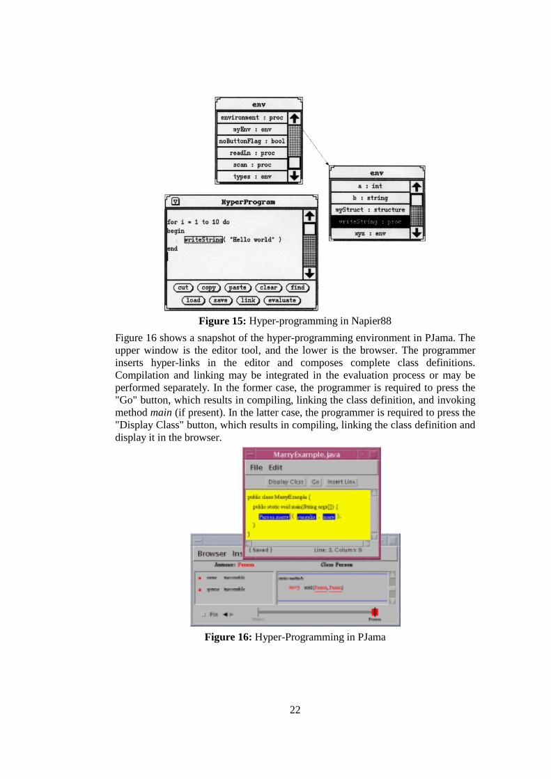
Implementations of hyper-programming can be found in both Napier88 [KCC+93] and JavaTM [ZKM98], [ZDK+99], [ZKM99], [MCD+99]. These, together with some other generic browsing tools [GR83], [OHK87], [DB88], [BOP+89], [Coo90], [KM97], provide a convenient and natural way for persistent programming environment users to browse the contents of the persistent store, avoiding the necessity to write down dynamically checked specifications to perform the equivalent accesses. The advantages of this style of access are comparable to the advantages of an iconic operating system interface over a traditional command-line based approach. Although the two implementations are built using two different languages, composing hyper-programs is performed in a similar way — the programmer types text and inserts hyper-links from the browser to the editor. This style of programming may be considered similar to the style introduced by the Visual Programming Environments, as the browsing facilities provided allow the visualisation of objects in the persistent store [CCK+94c]. Figure 15 shows a snapshot of the hyper-programming environment in Napier88. The top and the right window are browser windows, whereas the lower left is the editor window. A hyper-link may be inserted by selecting the desired item in the browser, and pressing the "Link" button in the editor window. Compilation, linking and execution are operations performed behind the scenes when evaluation is performed. However, the programmer is aware of these operations if an error occurs.
22
Figure 15: Hyper-programming in Napier88
Figure 16 shows a snapshot of the hyper-programming environment in PJama. The upper window is the editor tool, and the lower is the browser. The programmer inserts hyper-links in the editor and composes complete class definitions. Compilation and linking may be integrated in the evaluation process or may be performed separately. In the former case, the programmer is required to press the "Go" button, which results in compiling, linking the class definition, and invoking method main (if present). In the latter case, the programmer is required to press the "Display Class" button, which results in compiling, linking the class definition and display it in the browser.
Figure 16: Hyper-Programming in PJama

23
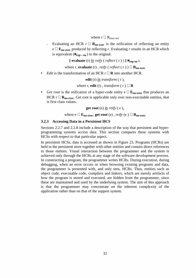
The main difference between this implementation of hyper-programming and the one in Napier88 is that the former supports multiple fonts, sizes, styles and colours, which can be customised by the programmer. Hyper-programming itself involves a further unifying step that simplified the programming development process. In hyper-programming, source programs are themselves persistent data, along with other values, with which they were manipulated [Kir92]. This is shown in Figure 17, where instead of textual descriptions of the dynamically checked access points, direct links from the source code to the persistent data are established. This is possible because these persistent data are available at the time when the program is composed. Programs may still contain assertions, which will be checked dynamically. Dynamic bindings only remain if there are references from the program. In the particular example, access to persistent data is achieved purely through direct links. Hyper-programming systems hide most of the accidents of traditional programming environments, such as different file formats. However, there are two different tools to support the browsing and editing. Each of these tools provide a different representation for data and programs respectively. Finally, both the systems do not provide debugging facilities.
program 1.1
persistent storeboundary
dynamically checked access points
hyper-links
program 2
e xe cu ta bleco de 1 .1
execu tablecode 1.2
executablecode 2
staticallycheckedcomponents(persistentdata)
program 1.2
References to data in the persistent store
Figure 17: Accessing source and executable code in HP systems
2.3 Towards Hyper-Code The hyper-code layer provides an abstract view of the software development process. Figure 18 outlines the unification steps towards hyper-code, as illustrated in Figure 4. Starting from traditional systems, each step has provided an extra unification concept and each has a particular way of accessing long-lived data in a file system, a database or a persistent store.

24
hyper-codehyper-programs
PS with codeas data
persistentsystems (PS)unifying short-
term and long-term data
unifying codeand data
unifying sourceprograms anddata
unifying sourceand executablecode
traditional
strongly typed data code as first class values source in the persistent store singlerepresentation
Figure 18: The unification chain towards a hyper-code system
Table 2 summarises the features provided by traditional programming environments (TR), persistent programming systems (PS), persistent programming systems with first class code (PS-FC), hyper-programming systems (HP) and hyper-code systems (HC), which will be described in detail in the next chapters. The features mentioned for each system involve: • whether the system is strongly typed, • whether the system supports first class code, • whether there is visual interaction with the programmer, involving provision of
the relevant user interface, • whether programs are held in the persistent storage area together with other
entities, • whether source and executable code are unified.
TR PS PS-FC HP HC
Strongly Typed * * * *
First class code * * *
Visual Interaction * * *
Source in PS * *
Unified Source & Executable *
Table 2: Comparison of features provided in various systems
2.4 Summary This chapter provides a survey of the related work in the area of programming environments, which attempt to hide accidental difficulties of the traditional programming life-cycle. Each of the programming environments described represents a category of software development systems related to the concepts of the thesis. The programming environments selected are: Emacs (General Editors), Visual Basic (Visual Programming Environments), CodeWarrior (Editor Based Programming Environments), Smalltalk and Trellis (Browser Based Programming Environments), ECLIPSE and APSE (Integrated Project Support Environments) and Hyper-Programming in Napier88 and PJama (Persistent Programming Environments).

25
Abstraction Unification Simplification
Emacs * CodeWarrior * Visual Basic * Smalltalk 80 * Trellis * HP (Napier88, PJama) * IPSEs * (Not applied) Hyper-Code Systems * * *
Table 3: Comparing various programming environments The description of these programming environments is based on whether these systems satisfy certain criteria. These criteria specified earlier in section 2.2 are: abstraction, unification and simplification. Table 3 summarises this description by comparing these systems with each other. The last row indicates whether hyper-code systems satisfy these criteria. Justification for this will be provided in the next chapter. Note that for IPSEs there is no notion of unification, that is a single representation for both programs and data, as these environments are built on top of existing tools. Hyper-Code extends the ideas related to persistence and hyper-programming. This is described in detail in the next chapters.

26
3 The Hyper-Code Abstraction — Towards Hyper-Code Systems
This chapter describes the hyper-code view of a programming system in terms of domains and operations over these domains. It then gives an overview of how these ideas may be mapped into concrete systems. The description included in this chapter is intended to be non-language specific.
3.1 The Hyper-Code View of the Programming Life-Cycle A programming system may be described in terms of two domains and four operations, which operate over the domains.
3.1.1 Defining the Domains The two domains are called E and R. E is the domain of language entities that contains all the first class values defined by the programming language – the Universe of Discourse – together with various denotable non-first class entities, such as types, classes and executable code. R is the domain of concrete representations of entities in domain E. A simple example is the integer value two in E and its representation 2 in R. As shown in Figure 19, domain E may be partitioned into a set of executable entities (Eexec) and a set of non-executable entities (Eno-exec). Furthermore, the executable entities Eexec may be partitioned into a set of executable entities that produce a result (Eexec-res), a set of executable entities that do not produce a result (Eexec-no-res) and a set of executable entities that produce either a static or dynamic error (Eexec-err).
E
Eexec Eno-exec
Eexec-res Eexec-no-res
has subsets
hassubsets
set of allentities
set of all non-executable
entities
set of all executable entities
set of all executableentities that produce
a result
set of all executable entitiesthat do not produce a result
Eexec-err
set of all executable entitiesthat produce an error
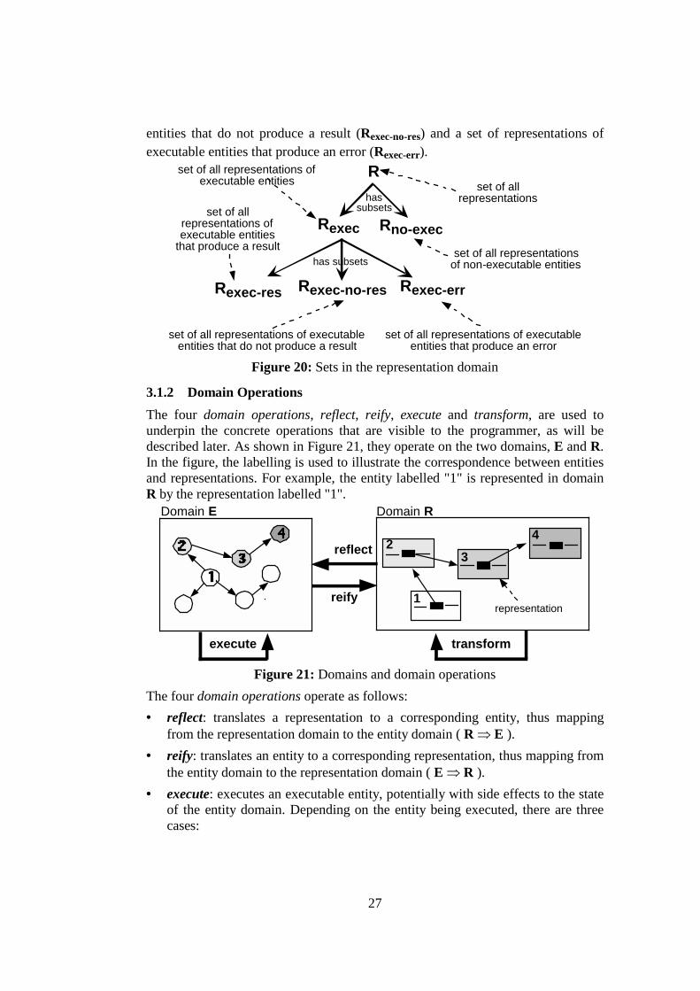
Figure 19: Sets in the entities domain Figure 20 illustrates how domain R may be partitioned into a set of representations of executable entities (Rexec) and a set of representations of non-executable entities (Rno-exec). Rexec may be partitioned into a set of representations of executable entities that produce a result (Rexec-res), a set of representations of executable
27
entities that do not produce a result (Rexec-no-res) and a set of representations of executable entities that produce an error (Rexec-err). R
Rexec Rno-exec
Rexec-res Rexec-no-res
has subsets
hassubsets
set of allrepresentations
set of all representationsof non-executable entities
set of all representations ofexecutable entities
set of allrepresentations ofexecutable entities
that produce a result
set of all representations of executableentities that do not produce a result
Rexec-err
set of all representations of executableentities that produce an error
Figure 20: Sets in the representation domain
3.1.2 Domain Operations The four domain operations, reflect, reify, execute and transform, are used to underpin the concrete operations that are visible to the programmer, as will be described later. As shown in Figure 21, they operate on the two domains, E and R. In the figure, the labelling is used to illustrate the correspondence between entities and representations. For example, the entity labelled "1" is represented in domain R by the representation labelled "1".
1
23
4reflect
Domain E Domain R
execute
representation
transform
reify
Figure 21: Domains and domain operations
The four domain operations operate as follows: • reflect: translates a representation to a corresponding entity, thus mapping
from the representation domain to the entity domain ( R ⇒ E ). • reify: translates an entity to a corresponding representation, thus mapping from
the entity domain to the representation domain ( E ⇒ R ). • execute: executes an executable entity, potentially with side effects to the state
of the entity domain. Depending on the entity being executed, there are three cases:
28
– the execution of an entity e ∈ Eexec-res produces a first class entity as a result, thus mapping from the entity domain to the entity domain ( Eexec-res ⇒ Eno-exec ).
– the execution of an entity e ∈ Eexec-no-res produces no result ( Eexec-no-res ⇒ no result).
– the execution of an entity e ∈ Eexec-err produces an error ( Eexec-err⇒ no result - error ).
• transform: manipulates a representation to produce another representation, thus mapping from the representation domain to the representation domain ( R ⇒ R ).
3.1.3 Composing Domain Operations – Equivalences The domain operations may be composed, and are used for the definition of the concrete operations within a particular system. The following equivalences hold: • the result of reflecting the representation of an entity e is an entity that is
equivalent ( ≡≡≡≡en ) to the original:
reflect ( reify ( e ) ) ≡en e
where e ∈ E and ≡≡≡≡en is equivalence over entities. The precise definition of the ≡≡≡≡en equivalence must be defined for each particular language when E is defined for that language. To give a hint of the nature of this equivalence in a particular setting, consider that some programming languages define equivalence over complex structures as identity (pointer equality), whereas others define it as (recursive) component equality.
• the result of reifying an entity produced by reflecting a representation r is itself a representation that is equivalent ( ≡≡≡≡rep-en ) to r:
reify ( reflect ( r ) ) ≡rep-en r
where r ∈ R and ≡≡≡≡rep-en is equivalence over representations i.e. r1 ≡≡≡≡rep-en r2 iff r1 and r2 represent equivalent entities, that is reflect ( r1 ) ≡≡≡≡en reflect ( r2 ). The implication here is that an entity may have more than one representation. In some cases the representations will be exactly the same:
reify ( reflect ( r ) ) ≡rep r
where r ∈ R and ≡≡≡≡rep is equivalence over representations and is defined precisely for a particular representation form.
• assuming that r is a representation of an entity e ∈ Eexec-res , the result of reifying an entity produced by executing e is a representation that is equivalent ( ≡≡≡≡rep-sub ) to r:
reify ( execute ( reflect ( r ) ) ) ≡rep-sub r
29
where r ∈ Rexec-res , reify ( execute ( reflect ( r ) ) ) ∈ Rno-exec and ≡≡≡≡rep-sub is substitutability of representations, that is r1 ≡≡≡≡rep-sub r2 iff any occurrence of r1 in a valid representation could be substituted by r2 and yield a valid representation. The intuition here is that the result of executing a fragment of code may be legally substituted for that fragment in the original. In a strongly typed language this means type equivalence.
3.1.4 Interpretations of the Domain Operations The above description of the domain operations is general and is given in order to explain the way that these operations map between the specified domains. Each domain operation or any of the above combinations of domain operations may be interpreted in various ways resulting in different semantics. For example, the execute policy may be partial evaluation or lazy evaluation [Dav92], [HM76] giving different semantics for the evaluation. Another example of different interpretation is whether the execute operation provides feedback of its state to the programmer, while it is performed. Finally, the result of evaluation may either replace the original representation or may be returned separately. However, the description of the domain operations, given in section 3.1.2, remains valid for every possible interpretation. Details of policies chosen for particular systems are given in section 4.2.
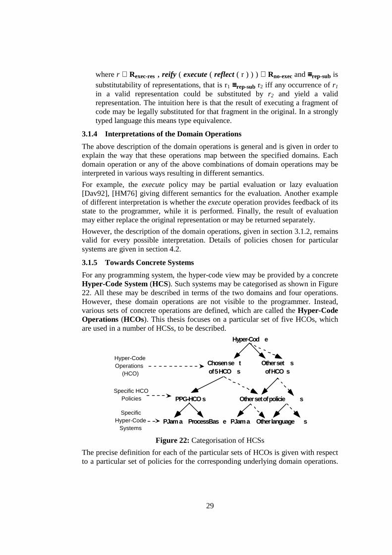
3.1.5 Towards Concrete Systems For any programming system, the hyper-code view may be provided by a concrete Hyper-Code System (HCS). Such systems may be categorised as shown in Figure 22. All these may be described in terms of the two domains and four operations. However, these domain operations are not visible to the programmer. Instead, various sets of concrete operations are defined, which are called the Hyper-Code Operations (HCOs). This thesis focuses on a particular set of five HCOs, which are used in a number of HCSs, to be described.
Hyper-Cod e
Chosen se tof 5 HCO s
Other set sof HCO s
PPG-HCO s
PJama ProcessBas e PJama
Hyper-CodeOperations
(HCO)
Specific HCOPolicies
SpecificHyper-Code
Systems
Other set of policie s
Other language s
Figure 22: Categorisation of HCSs The precise definition for each of the particular sets of HCOs is given with respect to a particular set of policies for the corresponding underlying domain operations.

30
This thesis focuses on a particular set of policies, termed the PPG1 policy set, and on two particular mappings of this set to specific HCSs. Note that the specification of different policies result in different HCSs, even if these are applied on the same language.
3.2 Hyper-Code Systems The features common to all HCSs are: • the HCS presents the programmer with a single, uniform representation, the
Hyper-Code Representation (HCR), for all code and data throughout all stages of the software development process. One possible single representation form is based on source code, which is in hyper-program form that can include direct links to existing entities. This will be described in greater detail in section 4.1.
• the HCS provides a single tool, the Hyper-Code Assistant (HCA), which fulfils the functions of both the browser and the editor in the hyper-programming system. It achieves this via the HCOs.
3.2.1 General Requirements for the Hyper-Code Operations The hyper-code operations support the use of a single representation as well as satisfying the following requirements: • the construction of new programs; • the editing of programs; • the insertion of bindings to entities into programs; • the browsing of representations of program and data in order to discover more
details about the internal structure of the entities they represent; • the execution and debugging of hyper-code representations. The above requirements are applicable to any set of HCOs. The thesis will now focus on one particular example set of HCOs, which forms the basis for the PPG policies set.
3.2.2 A Particular Set of HCOs A set of five HCOs is introduced. These are sufficient to fulfil the above requirements, and are applicable specifically to systems that involve the notion of persistence. These operations are: • explode: expands a selected HCR to show more detail, which is itself
expressed in the form of an HCR. The programmer may control the degree of detail displayed. This is explained in the context of a particular HCR form in section 4.2.5.
• implode: contracts a selected HCR to show less detail which is itself expressed in the form of an HCR (an exploded hyper-code representation is contracted back to its original form).
1 PPG stands for Persistent Programming Group and is a term that will be used for particular HCSs.

31
• evaluate: executes a selected HCR and returns the result, if any, as a new HCR.
• edit: encompasses all conventional editing facilities. • get root: returns a selected persistent root as an HCR. Explode and implode satisfy the requirement for browsing representations of programs and data. Evaluate satisfies the requirement of executing and debugging representations. Edit satisfies the requirement of constructing new programs as well as editing existing ones. Finally, get root creates bindings to values. In conjunction with the explode and edit operations, these bindings may then be inserted into programs. The HCOs are described in terms of the domain operations as follows: • Explode is the reification of reflecting an HCR r ∈ R. Exploding r results in a
more detailed HCR which is equivalent (≡≡≡≡rep-en) to the original. [ explode (r) is reify ( reflect ( r ) ) ] ≡≡≡≡rep-en r, where r, explode (r) , reify ( reflect ( r ) ) ∈ R
• Implode is also the reification of reflecting an HCR r ∈ R. Imploding r results in a less detailed HCR which is equivalent (≡≡≡≡rep-en) to the original.
[ implode (r) is reify ( reflect ( r ) ) ] ≡≡≡≡rep-en r, where r, implode (r) , reify ( reflect ( r ) ) ∈ R
• Evaluate is described as follows, depending on the HCR r ∈ R being evaluated: – Evaluating an HCR r ∈ Rexec-res is the reification of executing the entity
e ∈ Eexec-res, produced by reflecting r. Evaluating r results in an HCR
which is equivalent (≡≡≡≡rep-sub) to the original.
[ evaluate (r) is reify ( execute ( reflect ( r ) ) ) ] ≡≡≡≡rep-sub r,
where r ∈ Rexec-res, evaluate (r) , reify ( execute ( reflect ( r ) ) ) ∈ Rno-exec
– Evaluating an HCR r ∈ Rexec-no-res is the execution of an entity e ∈ Eexec-no-res produced by reflecting r.
evaluate (r) is execute ( reflect ( r ) ),
where r ∈ Rexec-no-res
– Evaluating an HCR r ∈ Rexec-err is either the execution of an entity e ∈ Eexec-err produced by reflecting r, or just the reflection of r. The particular set of domain operations that evaluate involves in this case depends on whether the error is dynamic or static respectively. In either case the error is produced and displayed to the programmer.
evaluate (r) is execute ( reflect ( r ) ), if the error is dynamic
evaluate (r) is reflect ( r ), if the error is static
32
where r ∈ Rexec-err
– Evaluating an HCR r ∈ Rno-exec is the reification of reflecting an entity e ∈ Eno-exec produced by reflecting r. Evaluating r results in an HCR which is equivalent (≡≡≡≡rep—en ) to the original.
[ evaluate (r) is reify ( reflect ( r ) ) ] ≡≡≡≡rep-en r,
where r, evaluate (r) , reify ( reflect ( r ) ) ∈ Rno-exec • Edit is the transformation of an HCR r ∈ R into another HCR.
edit (r) is transform ( r ), where r, edit (r) , transform ( r ) ∈ R
• Get root is the reification of a hyper-code entity e ∈ Eno-exec that produces an HCR r ∈ Rno-exec. Get root is applicable only over non-executable entities, that is first class values.
get root (e) is reify ( e ),
where e ∈ Eno-exec, get root (e) , reify (e ) ∈ Rno-exec
3.2.3 Accessing Data in a Persistent HCS Sections 2.2.7 and 2.2.8 include a description of the way that persistent and hyper-programming systems access data. This section compares these systems with HCSs with respect to that particular aspect. In persistent HCSs, data is accessed as shown in Figure 23. Programs (HCRs) are held in the persistent store together with other entities and contain direct references to those entities. Visual interaction between the programmer and the system is achieved only through the HCRs at any stage of the software development process. In constructing a program, the programmer writes HCRs. During execution, during debugging, when an error occurs or when browsing existing programs and data, the programmer is presented with, and only sees, HCRs. Thus, entities such as object code, executable code, compilers and linkers, which are merely artifacts of how the program is stored and executed, are hidden from the programmer, since these are maintained and used by the underlying system. The aim of this approach is that the programmer may concentrate on the inherent complexity of the application rather than on that of the support system.
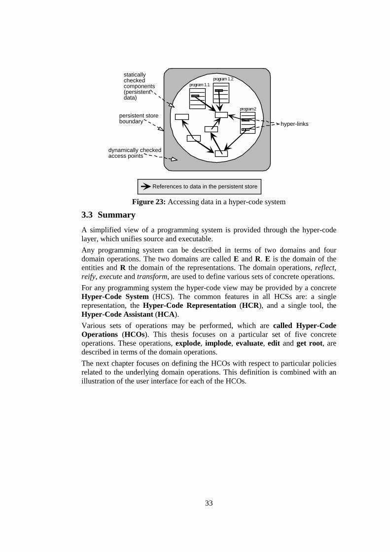
33
program 1.1
persistent storeboundary
dynamically checked access points
hyper-links
program 2
staticallycheckedcomponents(persistentdata)
program 1.2
References to data in the persistent store
Figure 23: Accessing data in a hyper-code system
3.3 Summary A simplified view of a programming system is provided through the hyper-code layer, which unifies source and executable. Any programming system can be described in terms of two domains and four domain operations. The two domains are called E and R. E is the domain of the entities and R the domain of the representations. The domain operations, reflect, reify, execute and transform, are used to define various sets of concrete operations. For any programming system the hyper-code view may be provided by a concrete Hyper-Code System (HCS). The common features in all HCSs are: a single representation, the Hyper-Code Representation (HCR), and a single tool, the Hyper-Code Assistant (HCA). Various sets of operations may be performed, which are called Hyper-Code Operations (HCOs). This thesis focuses on a particular set of five concrete operations. These operations, explode, implode, evaluate, edit and get root, are described in terms of the domain operations. The next chapter focuses on defining the HCOs with respect to particular policies related to the underlying domain operations. This definition is combined with an illustration of the user interface for each of the HCOs.

34
4 Concrete Hyper-Code System The purpose of a Hyper-Code System (HCS) is to provide the programmer with a conceptually simple user interface with which to manipulate a single representation of a program throughout its life time, the hyper-code representation (HCR). This user interface is provided by the hyper-code assistant (HCA) through which all the Hyper-Code Operations (HCOs) are performed. The requirements for choosing an appropriate HCR and the operations performed in a HCS through the HCA, will be described in this chapter. To illustrate the hyper-code concepts, the examples given are for a non-language specific HCA. Concrete examples in particular programming languages are given later.
4.1 The Hyper-Code Representation Hyper-code may be implemented for any suitable language. The precise form of the hyper-code representation will vary depending on the syntax of the particular language, but will be guided by the following criteria that will apply for all languages: • The HCR must accommodate programs written in the convention of the
language. Normally this implies that the HCR must include pure text as a subset.
• The HCR must accommodate the one to one mapping (unification) between executable and source code. To achieve that, representation of closure is required, which consists of code and the environment under which it is executed. The environment may contain shared values that are bound into it at the time it is formed, and in languages with update, the values in the locations may change. Where the sharing is significant, such as in the preservation of identity, then a purely textual representation is not sufficient. In order for the HCR to completely represent closure, direct links to entities are used, to preserve the sharing, as explained in [CCK+94c].
• The HCR must support views of linked entities, to arbitrary levels of detail. • The views of entities must themselves include text and direct links in the same
form as could be constructed by the programmer, since there is only a single HCR.
• Finally, the views must be self-contained and syntactically valid. Thus, for any view of an entity, it should be possible to copy its representation, and evaluate it without error. The result of this evaluation will depend on the semantics of the particular language.
A hyper-program, which is a combination of text and hyper-links to entities, is suitable for use as an HCR. An HCR can be produced for every entity in domain E, with its precise form depending on the kind of entity being represented. This form will be illustrated later in this thesis, where domain E will be defined for the particular languages ProcessBase and PJama. Similarly, the way that each hyper-link is presented depends on the kind of entity that it represents. Figure 24 shows an example of the general form of a HCR

35
contained in a HCA window, in which the horizontal lines indicate text. In this, a hyper-link is represented by a rounded box with no label and a background colour denoting the kind of entity it represents. Customisations may be applied in order to change the way that hyper-links are displayed. For example, it should be possible to customise hyper-links to be displayed as WWW links. In Figure 24 there are three hyper-links. Hyper-Link 1 itself contains an HCR that is text and a hyper-link to an entity (Hyper-Link 2).
Hyper-Code Assistant
Hyper-Link 1
Hyper-Link 2Hyper-Link 3 Figure 24: An example HCA window containing an HCR
4.2 A Particular Set of Hyper-Code Operations The hyper-code operations, introduced in section 3.2.2, are performed in windows provided by the HCA tool, an example of which is shown in Figure 24. Each of the operations is described with respect to a particular interpretation (policy) of the corresponding underlying domain operations. This interpretation is the system’s default behaviour. Other interpretations may be available as add-in customisations. One of the major features of these HCOs, which distinguishes them from conventional programming operations, is the ability to inspect the entities represented by hyper-links at any time of the software development process. This includes inspection of the current values of variables during evaluation, where the programmer is presented with a changing HCR, as will be explained later in section 4.2.3.
4.2.1 Explode The explode operation is performed for each hyper-link in the selected representation. Exploding each hyper-link results in a more detailed HCR, that is equivalent (≡≡≡≡rep-en) to the original contracted hyper-link. The semantics for explode are determined by the interpretations chosen for the underlying operations, which involve the following policies: • reflection is a direct translation of source code. • reification returns a more detailed HCR that replaces the original hyper-link. The HCR resulting from explode is non-editable. This ensures that a representation accurately denotes the entity at all times. The exploded representation still denotes the same entity as the original hyper-link. However, the programmer is able to copy this representation and manipulate the copy elsewhere. In Figure 24, Hyper-
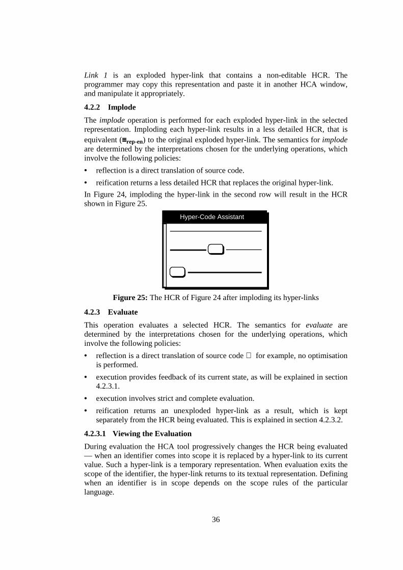
36
Link 1 is an exploded hyper-link that contains a non-editable HCR. The programmer may copy this representation and paste it in another HCA window, and manipulate it appropriately.
4.2.2 Implode The implode operation is performed for each exploded hyper-link in the selected representation. Imploding each hyper-link results in a less detailed HCR, that is equivalent (≡≡≡≡rep-en) to the original exploded hyper-link. The semantics for implode are determined by the interpretations chosen for the underlying operations, which involve the following policies: • reflection is a direct translation of source code. • reification returns a less detailed HCR that replaces the original hyper-link. In Figure 24, imploding the hyper-link in the second row will result in the HCR shown in Figure 25.
Hyper-Code Assistant
Figure 25: The HCR of Figure 24 after imploding its hyper-links
4.2.3 Evaluate This operation evaluates a selected HCR. The semantics for evaluate are determined by the interpretations chosen for the underlying operations, which involve the following policies: • reflection is a direct translation of source code for example, no optimisation
is performed. • execution provides feedback of its current state, as will be explained in section
4.2.3.1. • execution involves strict and complete evaluation. • reification returns an unexploded hyper-link as a result, which is kept
separately from the HCR being evaluated. This is explained in section 4.2.3.2.
4.2.3.1 Viewing the Evaluation During evaluation the HCA tool progressively changes the HCR being evaluated — when an identifier comes into scope it is replaced by a hyper-link to its current value. Such a hyper-link is a temporary representation. When evaluation exits the scope of the identifier, the hyper-link returns to its textual representation. Defining when an identifier is in scope depends on the scope rules of the particular language.

37
Identifiers are the only entities that are replaced by hyper-links during evaluation. Statically defined hyper-links remain unchanged. The HCR may also contain representations of executable entities that return a result, e.g. "1+1". Depending on the execution policy such expressions may be presented to the programmer in various ways — for example during evaluation the programmer could be presented with a hyper-link representing the result of executing this expression. However, since the execution policy defined here involves strict and complete evaluation, such representations remain unchanged during evaluation. As the HCR is evaluated, a progress bar on the left of the HCR denotes the current line. As with statically defined hyper-links, hyper-links to identifiers can be exploded in order to inspect their current values. Exploding can be performed at any time, whether the HCR is being evaluated or evaluation has been interrupted. Any exploded hyper-link to a mutable location, where provided by the language, is automatically updated to display any new values assigned to the location. The evaluation process may be interrupted either when an error occurs, or when a breakpoint is reached. In the case of a static error, the programmer is notified of the position where the error is detected. In the case of a dynamic error or when a breakpoint is reached, evaluation is suspended. Breakpoints are set during composition, as will be explained later in this chapter. Figure 26 illustrates three snapshots of evaluating an example HCR, which initially contains two hyper-links and an identifier (x). The indentation of lines indicates different scope levels. Figure 26(a) shows the HCR during composition, where the identifier x is represented textually. The hyper-links here are links to entities in the persistent store. These can be thought of as anonymous values that are always in scope for the HCR being evaluated. When evaluation reaches the point indicated by the progress bar shown in Figure 26(b), i.e. when x comes into extent, all textual representations of the identifier x currently in scope are replaced by hyper-links. On exiting the scope of x, the hyper-link representing the identifier x is returned to its textual representation; this is illustrated in Figure 26(c).
Hyper-Code Assistant Hyper-Code Assistant
(a) (b ) (c)
Scope Level 0Scope Level 1 Scope Level 1 Scope Level 1
Scope Level 0Scope Level 0
Entering scope level 0(Identifier x out of scope)
Entering scope level 1(Identifier x is declared)
Exiting scope level 1(Identifier x out of scope)
<declaration of x>
Hyper-Code Assistant
<declaration of x>
x<declaration of x>
x
Figure 26: Snapshots of the evaluation process

38
4.2.3.2 Result of Evaluation The evaluation of an HCR r returns a result if r represents:
• an executable entity that returns a result ( r ∈ Rexec-res )
• a non-executable entity ( r ∈ Rno-exec ) When evaluation produces a result, this is returned as a hyper-link. By default, as introduced earlier, the result of evaluation is kept separately from the original HCR and is inserted in the same HCA window as the original HCR, right after that representation. A possible customisation is for the resulting hyper-link to replace the original HCR. Another is to preserve the original HCR and insert the resulting hyper-link in another position, such as the clipboard or a newly created HCA window.
The resulting hyper-link is an HCR equivalent ( ≡≡≡≡rep-sub ) to the original. In the case of evaluating a single hyper-link, the resulting HCR is defined to be ≡≡≡≡rep equivalent to the original. The ≡≡≡≡rep equivalence is defined as follows (if two representations are ≡≡≡≡rep equivalent, they are automatically ≡≡≡≡rep-sub equivalent):
≡≡≡≡rep : two hyper-code representations are equivalent ( ≡≡≡≡rep ) iff each corresponding hyper-code character is equivalent. A hyper-code character may either be an ASCII character or a hyper-link. Two hyper-links are equivalent if they represent equivalent ( ≡≡≡≡en ) entities. Equivalence over hyper-code entities is language specific.
4.2.4 GetRoot This operation produces a hyper-link for each persistent root. The semantics for getRoot are determined by the interpretations chosen for the underlying operations, which involve the following policy: • reification returns an unexploded hyper-link as a result, which is inserted in a
specific HCA window. All the resulting hyper-links are contained in a non-editable hyper-code window, as shown in Figure 27.
Hyper-Code Assistant
a link to apersistent root
Figure 27: The persistent roots HCA window
4.2.5 Edit This operation encompasses the conventional editing facilities and other facilities related to the manipulation of the hyper-code representations. The semantics for edit are determined by the interpretations chosen for the underlying operations, which involve the following policy:
39
• transformation is unconstrained in that any sequence of text and hyper-links may be constructed2.
The following editing facilities are provided through the HCA window: • create a new hyper-code window. • compose HCRs: HCRs are edited in a similar way to text in conventional
text-editors. The HCA supports navigation using keyboard and mouse, embedded hyper-links of arbitrary size, which are treated in the same way as characters, and the standard editing facilities such as: – typing: inserts and deletes plain text. – drag and drop: drags a selected HCR and drops it in the same or in a
different HCA window. The programmer may choose whether this operation results in copying or moving.
– cut: deletes the selected HCR and stores it in the clipboard. – copy: creates a copy of the selected HCR and stores it in the clipboard. – paste: inserts the HCR stored in the clipboard at the current insertion point
of the HCA window, replacing any selected HCR. • set/remove a breakpoint: adds a breakpoint at the line containing the
insertion point, in which case a bullet is displayed on the left of the line. The PPG-HCS also provides the following facilities: • editable clipboard: the programmer is able to see the contents of the clipboard
via the clipboard window, which is an editable HCA window. • multiple faces: the programmer is able to change the way that HCRs are
displayed in the HCA window, since the system supports multiple fonts, sizes, styles and colours.
• update of locations: the programmer is able to update the value of a location, where provided by the language, without having to compose a new HCR. Such an update is achieved by dragging a hyper-link representing a first class value and dropping it over a hyper-link to a location of the appropriate type. This operation is only applicable if locations are treated as first class values.
• customisation mechanism: the user is able to customise the way HCRs are displayed. The customisation mechanisms provided are: – customise hyper-links: this changes the way unexploded hyper-links are
displayed. There are two kinds of customisation: – customise particular hyper-links: the programmer may add a label to
a hyper-link or display it as an image or display it as an WWW link. – customise hyper-links representing values of a particular type: the
programmer can customise hyper-links representing values of a particular type. The system lets the programmer customise these
2 In contrast, for example, a different strategy could be used in a syntax-directed editor, where only
certain HCRs could be constructed.

40
hyper-links as an image or a string or a WWW link. The user interface for this kind of customisation depends on the language.
– customise levels of expansion for explode: this specifies the levels of expansion when the explode operation is performed. The system's default value is one, which means that explode results in a detailed HCR that contains text and unexploded hyper-links. If, for example, the programmer sets the value to two, then when a hyper-link is exploded it produces an HCR, in which the hyper-links included are exploded in turn.
• other features: HCRs may be printed. There is also a search facility where the programmer may search for an HCR. HCR matching is defined by the ≡≡≡≡rep equivalence. In Figure 28, the programmer searches for the specified hyper-link in every HCA window.
Search for :
Search Close
Figure 28: Searching in a HCS
4.3 Summary A Hyper-Code System (HCS) provides the programmer with a conceptually simple user interface through which specific Hyper-Code Operations (HCOs) are performed over a single representation, the Hyper-Code Representation (HCR). A representation that fulfils certain criteria is the hyper-program form, as explained in section 4.1. The particular HCOs are: explode, implode, evaluate, get root and edit. This chapter defines the chosen operations with respect to particular interpretations of the corresponding underlying domain operations. The appearance of the user interface for each of these operations is also illustrated. The description in chapters 5 and 6 is given for completeness, that is to illustrate the way that mapping of the PPG-HCS policy set into particular HCSs in particular languages can be achieved. The languages are: ProcessBase [MBG+99b], a simple persistent language, and PJama [ADJ+96], a persistent version of Java.

41
5 A Hyper-Code System for ProcessBase ProcessBase [MBG+99b], [MBG+99d] is the simplest of a family of languages and support systems designed for process modelling. It consists of the language and its persistent environment. The persistent store is populated and the system uses objects within the persistent store to support itself. The model of persistence in ProcessBase is that of reachability from a root object. ProcessBase obeys the principles of correspondence, abstraction and type completeness [Mor79]. It is the belief of the designers that such an approach to language design yields more powerful and less complex languages. The ProcessBase type system philosophy is that types are sets of values from the value space. The type system is mostly statically checkable, a property highly desirable wherever possible. The type equivalence rule in ProcessBase is by structure and both aliasing and recursive types are allowed in the type algebra.
5.1 Domains in ProcessBase There are two distinct domains in the ProcessBase HCS, domain E and domain R. Domain E contains all the first class values, identifiers, types and code. Code is any executable entity, e.g. an expression performing addition between two integers. Identifiers are of specific types. Types are classified into base types and constructed types. Base types are: scalars, type string, type any. Type constructors are: location, vector, view, procedure. These are defined in the ProcessBase language specification [MBG+99b]. Every entity in domain E has its corresponding HCR in the domain R. Each representation is a combination of text and hyper-links to entities. A hyper-link is displayed by default as a rounded box with no label. The background colour indicates if the hyper-link represents a type, or a value or an identifier3. Hyper-links representing identifiers have different appearance from first class values. Table 4 illustrates the appearance of representations of entities in domain E. Every entity in domain E, except code, can be represented by a single hyper-link in domain R.
3 White for first class values, black for types and patterned-grey for identifiers.

42
Entity in E HCR in R
identifier scalar value, string, any, location, vector, view, procedure, interrupt, op-code
type code any combination of text and hyper-links
e.g. the representation of an expression that adds two integers could be
+ Table 4: Appearance of representations of ProcessBase entities
5.2 Equivalences in ProcessBase Hyper-Code As stated earlier, four kinds of equivalences are defined in a HCS; three equivalences over HCRs ( ≡≡≡≡rep, ≡≡≡≡rep-en and ≡≡≡≡rep-sub ), which have already been defined, and an equivalence over hyper-code entities ( ≡≡≡≡en ). Table 5 defines the ≡≡≡≡en equivalence over ProcessBase entities.
Entity in E ≡≡≡≡en
identifier Same name and scope first class value, interrupt, op-code
Equality as defined in ProcessBase language specification (PBLS)
type Type equivalence as defined in PBLS code Same sequence of instructions
Table 5: Definition equivalence over ProcessBase entities in E Type equivalence and equality between values are defined in the ProcessBase language specification [MBG+99b]. Type equivalence in ProcessBase is based upon the meaning of types, and is independent of the way types are expressed within the type algebra. This style of type equivalence is normally referred to as structural equivalence. According to the structural equivalence rules, every base type is equivalent only to itself, and for two constructed types to be equivalent, they must have the same constructor and be constructed over equivalent types. All values in ProcessBase have first class citizenship except interrupts and op-codes. This implies that they have the right to be declared, to be assigned, to have equality defined over them, and to persist. The ProcessBase language specification defines equality over first class values, as follows: • Two strings are equal if they have the same characters in the same order and
are of the same length. • Two values of type any are equal if they can be projected onto equivalent types
and the projected values are equal.
43
• Two locations or vectors or views are equal if they have the same identity, that is, the same pointer.
• Two procedures are equal if their values are derived from the same evaluation of the same procedure expression, that is, they have the same closure.
5.3 Operations Over HCRs The HCOs are performed through the HCA over the HCRs. The HCOs, explode, implode, evaluate, get root and edit, will be described in the following sections.
5.3.1 Explode In the explode operation, each hyper-link in the selected representation is enlarged to show a more detailed HCR which is equivalent ( ≡≡≡≡rep-en) to the original contracted hyper-link. The exploded representation is a valid ProcessBase fragment. Operation explode follows the reflection and reification policies introduced in section 4.2.1. Table 6 shows examples of exploding hyper-links to identifiers, first class values, interrupts and op-codes.

44
Hyper-link to...
Examples of exploded hyper-links
Description
identifier 2
value of the identifier
int, real, bool
2 2.0 true, , literal values of types integer, real and boolean respectively
string "vangelis"
string value
any any( )
a value, represented by a hyper-link, injected into any
location loc ( )
a location containing a value represented by a hyper-link
vector vector @1 of [ , , ] a vector with values
represented by hyper-links as elements
view view ( name <- ; age <- ) a view with its fields
initialised with values represented by hyper-links
procedure fun() -> ;
a procedure with no parameters, return type represented by the first hyper-link and a value represented by the second hyper-link as body
interrupt clocktick
an identifier of an interrupt
op-code opcode1
an identifier of an op-code
Table 6: Exploding hyper-links to ProcessBase values and identifiers Table 7 shows examples of exploding hyper-links to base and constructed ProcessBase types. Note that interrupt and op-code types can not be hyper-linked.
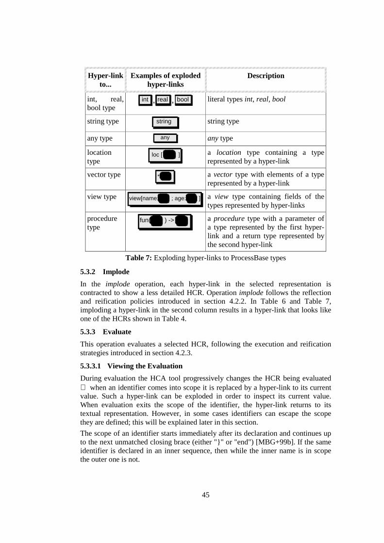
45
Hyper-link to...
Examples of exploded hyper-links
Description
int, real, bool type
int real bool,, literal types int, real, bool
string type string
string type
any type
any any type
location type
loc [ ]
a location type containing a type represented by a hyper-link
vector type *
a vector type with elements of a type represented by a hyper-link
view type view[name: ; age: ] a view type containing fields of the
types represented by hyper-links
procedure type
fun( ) ->
a procedure type with a parameter of a type represented by the first hyper-link and a return type represented by the second hyper-link
Table 7: Exploding hyper-links to ProcessBase types
5.3.2 Implode In the implode operation, each hyper-link in the selected representation is contracted to show a less detailed HCR. Operation implode follows the reflection and reification policies introduced in section 4.2.2. In Table 6 and Table 7, imploding a hyper-link in the second column results in a hyper-link that looks like one of the HCRs shown in Table 4.
5.3.3 Evaluate This operation evaluates a selected HCR, following the execution and reification strategies introduced in section 4.2.3.
5.3.3.1 Viewing the Evaluation During evaluation the HCA tool progressively changes the HCR being evaluated when an identifier comes into scope it is replaced by a hyper-link to its current value. Such a hyper-link can be exploded in order to inspect its current value. When evaluation exits the scope of the identifier, the hyper-link returns to its textual representation. However, in some cases identifiers can escape the scope they are defined; this will be explained later in this section. The scope of an identifier starts immediately after its declaration and continues up to the next unmatched closing brace (either "}" or "end") [MBG+99b]. If the same identifier is declared in an inner sequence, then while the inner name is in scope the outer one is not.
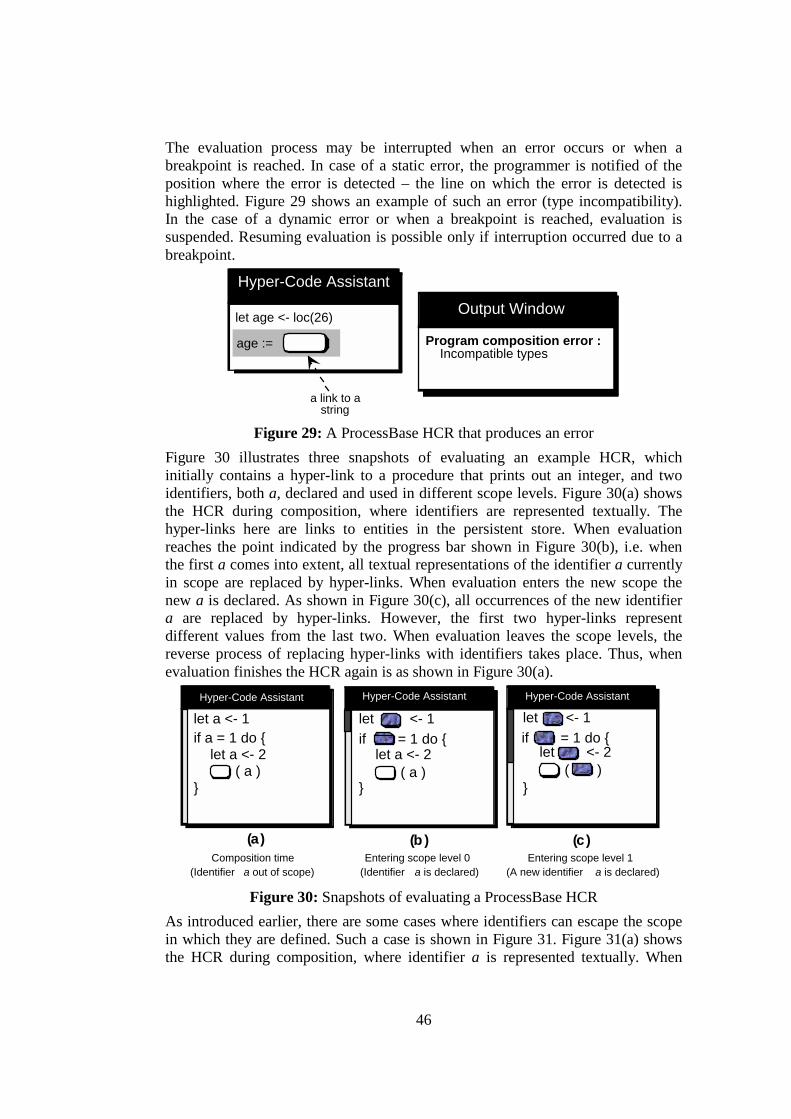
46
The evaluation process may be interrupted when an error occurs or when a breakpoint is reached. In case of a static error, the programmer is notified of the position where the error is detected – the line on which the error is detected is highlighted. Figure 29 shows an example of such an error (type incompatibility). In the case of a dynamic error or when a breakpoint is reached, evaluation is suspended. Resuming evaluation is possible only if interruption occurred due to a breakpoint.
Output Window
Hyper-Code Assistant
age := Program composition error : Incompatible types
let age <- loc(26)
a link to astring
Figure 29: A ProcessBase HCR that produces an error Figure 30 illustrates three snapshots of evaluating an example HCR, which initially contains a hyper-link to a procedure that prints out an integer, and two identifiers, both a, declared and used in different scope levels. Figure 30(a) shows the HCR during composition, where identifiers are represented textually. The hyper-links here are links to entities in the persistent store. When evaluation reaches the point indicated by the progress bar shown in Figure 30(b), i.e. when the first a comes into extent, all textual representations of the identifier a currently in scope are replaced by hyper-links. When evaluation enters the new scope the new a is declared. As shown in Figure 30(c), all occurrences of the new identifier a are replaced by hyper-links. However, the first two hyper-links represent different values from the last two. When evaluation leaves the scope levels, the reverse process of replacing hyper-links with identifiers takes place. Thus, when evaluation finishes the HCR again is as shown in Figure 30(a).
if = 1 do {let <- 1
let <- 2( )
}
(a)
Hyper-Code Assistant
if a = 1 do {let a <- 1
let a <- 2( a )
}
(b ) (c)
let <- 1if = 1 do {
let a <- 2( a )
}
Hyper-Code Assistant Hyper-Code Assistant
Composition time (Identifier a out of scope)
Entering scope level 0 (Identifier a is declared)
Entering scope level 1 (A new identifier a is declared)
Figure 30: Snapshots of evaluating a ProcessBase HCR As introduced earlier, there are some cases where identifiers can escape the scope in which they are defined. Such a case is shown in Figure 31. Figure 31(a) shows the HCR during composition, where identifier a is represented textually. When

47
evaluation reaches the point indicated by the progress bar shown in Figure 31(b), i.e. when a comes into extent, all textual representations of the identifier a currently in scope are replaced by hyper-links. When evaluation terminates, these hyper-links are replaced again by the textual representations of a.
(a )
Hyper-Code Assistant
fun() -> int; 'alet a <- loc( 1 )
(b )
let <- loc( 1 )fun() -> int; '
Hyper-Code Assistant
Composition time (Identifier a out of scope)
Entering scope level 0 (Identifier a is declared)
Figure 31: An example of an identifier that escapes its scope As will be explained later, the result of this evaluation is a hyper-link representing the procedure. When this hyper-link is exploded, to show the procedure code, the identifier a is denoted by a hyper-link to its value. This follows since the procedure source code is recorded at the point of closure formation, at which point the identifier a has been replaced by the link. Figure 32 shows the result of evaluating the particular HCR, where the hyper-link representing the location is exploded in turn.
Hyper-Code Assistant
fun() -> int; ' loc( 1 )
Figure 32: An HCR representing a closure
5.3.3.2 Result of Evaluation The result of evaluation depends on the HCR being evaluated. Table 8 illustrates examples of representations that return a result, where the first column contains the domain of the HCR being evaluated, the second column an example HCR and the third column the result of evaluating this HCR. The HCR in the first row represents an executable entity that returns a result – two values of type int are added and the result is returned as a hyper-link. The HCR in the second row represents a non-executable entity – a single hyper-link is evaluated. Evaluating any other representation returns either no result or an error.

48
Representation category – Domain
Example of representation Result of evaluating the representation
An executable representation that returns a result (Rexec-res)
+
a link to aninteger
a link to aninteger
a link to aninteger
A non-executable representation (Rno-exec)
a link to aninteger
a link to aninteger
Table 8: Evaluating ProcessBase HCRs
The resulting hyper-link is an HCR equivalent ( ≡≡≡≡rep-sub ) to the original. In the case of evaluating a single hyper-link, as in row 2, the resulting HCR is defined to be ≡≡≡≡rep equivalent to the original.
5.3.4 Get Root In ProcessBase, this operation produces a hyper-link for a persistent root. The hyper-link is contained in a non-editable hyper-code window, as shown in Figure 33. Operation get root follows the reification policy introduced in section 4.2.4.
Hyper-Code Assistanta link to apersistent root
Figure 33: The persistent roots HCA window
5.3.5 Edit This operation follows the transformation policy introduced in section 4.2.5. It encompasses the basic conventional editing facilities and some other facilities related to the graphical user interface. Composing HCRs involves typing, drag and drop, cut, copy and paste. A snapshot of composing an HCR is shown in Figure 34.
Hyper-Code Assistant
:= nloc ( )
1
let myFunction <- fun( n: ) ->int* int
begin
endvector to using
5 fun( a : ) -> ; aintint
Figure 34: Composing a ProcessBase HCR
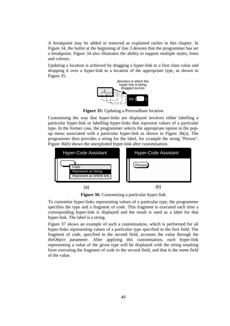
49
A breakpoint may be added or removed as explained earlier in this chapter. In Figure 34, the bullet at the beginning of line 3 denotes that the programmer has set a breakpoint. Figure 34 also illustrates the ability to support multiple styles, fonts and colours. Updating a location is achieved by dragging a hyper-link to a first class value and dropping it over a hyper-link to a location of the appropriate type, as shown in Figure 35.
loc ( )
2
direction in which thehyper-link is being
dragged across
Figure 35: Updating a ProcessBase location
Customising the way that hyper-links are displayed involves either labelling a particular hyper-link or labelling hyper-links that represent values of a particular type. In the former case, the programmer selects the appropriate option in the pop-up menu associated with a particular hyper-link as shown in Figure 36(a). The programmer then provides a string for the label, for example the string "Person". Figure 36(b) shows the unexploded hyper-link after customisation.
Hyper-Code Assistant
CopyRepresent as String
Hyper-Code Assistant
Person
(a) (b)
Represent as WWW link
Figure 36: Customising a particular hyper-link
To customise hyper-links representing values of a particular type, the programmer specifies the type and a fragment of code. This fragment is executed each time a corresponding hyper-link is displayed and the result is used as a label for that hyper-link. The label is a string. Figure 37 shows an example of such a customisation, which is performed for all hyper-links representing values of a particular type specified in the first field. The fragment of code, specified in the second field, accesses the value through the theObject parameter. After applying this customisation, each hyper-link representing a value of the given type will be displayed with the string resulting from executing the fragment of code in the second field, and that is the name field of the value.

50
Customise Type: (using theObject )
Customise as String: theObject.name
Customise Cancel
view(name:string; age:int)
Customise as WWW link:
Figure 37: Customising hyper-links representing values of the specified type
5.4 Summary This chapter described the mapping of a particular HCS into ProcessBase. The domain E, in a concrete HCS in ProcessBase, contains identifiers, code, types and the first class values as specified in the ProcessBase language specification. Every entity in domain E has a corresponding HCR in R. The particular HCOs, explode, implode, evaluate, get root and edit, operate over these HCRs. This chapter illustrated the user interface for each of these operations.
51
6 A Hyper-Code System for PJama JavaTM is an object-oriented, architecture-neutral, interpreted language that supports multithreaded programming and distribution and provides encapsulation, inheritance and polymorphism [NA99]. An example of adding persistence to Java is an orthogonally persistent Java, PJama [ADJ+96], which obeys the design principles of persistence as stated in [AM95]. The particular implementation of adding persistence to JavaTM was motivated by attempting to achieve a much broader set of facilities in an industrially supported language to demonstrate that orthogonal persistence is beneficial for large commercial programming projects [AJD+96]. The main goal of PJama was to add persistence to the existing language with minimal change to its initial semantics and implementation. This requires the language to provide a basic number of facilities, which are stated in [MCK+96], and involve an infinite union type with injection and projection operations, facilities for linguistic reflection, and a persistent store with root(s), reachability and referential integrity. The following sections describe the design of a HCS in PJama.
6.1 Domains in PJama There are two distinct domains in the PJama HCS, domain E and domain R. Domain E contains code, variables, types, and all the first class values. Code is any executable entity. The variable is the basic unit of storage in a Java program and is defined by the combination of an identifier, a type and a value. A first class value is: a primitive value, that is value of a primitive type, an array, or an instance of a class. Types are classified into elemental (primitive) types and reference types. Primitive types include integers (byte, short, int, long), floating-point numbers (float, double), characters (char) and booleans (boolean). Reference types include classes, interfaces and array types. Every entity in domain E has its corresponding HCR in the domain R. Each representation is a combination of text and hyper-links to entities. A hyper-link is displayed by default as a rounded box with no label. The background colour indicates if the hyper-link represents a type, or a value or a variable4. Every hyper-link representing a type or a first class value can be manipulated in the same way, which means that every hyper-code operation can be performed over it. Hyper-links to variables are transient and are only created during evaluation, as will be explained later. Table 9 illustrates the appearance of representations of entities in domain E. Every entity in domain E, except code, can be represented by a single hyper-link in domain R.
Entity in E Hyper-Code Representation in R
4 White for first class values, black for types and patterned-grey for variables.

52
variable primitive value, Array, Object primitive type, class, interface, array Type
code any combination of text and hyper-links e.g. the HCR of an expression that adds
two integers could be +
Table 9: Appearance of representations of PJama entities
6.2 Equivalences in PJama As stated earlier, four equivalences are defined in a HCS; three equivalences over HCRs (≡≡≡≡rep, ≡≡≡≡rep-en and ≡≡≡≡rep-sub ), which have already been defined earlier, and an equivalence over hyper-code entities ( ≡≡≡≡en ). Table 10 defines the ≡≡≡≡en equivalence over PJama entities.
Entity in E ≡≡≡≡en
variable Same name and scope primitive value, array, object
Equality as defined in Java language specification
primitive and reference type
Type equivalence as defined in Java language specification
code Same sequence of instructions
Table 10: Definition of the ≡en equivalence over PJama entities in E Type equivalence and equality between values are defined in the Java Language Specification (JLS) [GJS96]. According to the JLS, two arrays or objects are equal if they have the same identity. Type equivalence is based upon the following rules: • Every primitive type is equivalent only to itself, • Two reference types are equivalent if:
– either they are loaded by the same class loader, and have the same fully-qualified name, in which case they are said to be the same class or the same interface.
– or they are both array types, and have the same component type.
6.3 Operations Over HCRs The HCOs are performed through the HCA window over HCRs. The HCOs, explode, implode, evaluate, get root and edit, will be described in the following sections, using the class definitions shown in Figure 38.

53
public class Person extends Animal { public String name; public Person(String name) { this.name = name; noOfLegs = 2; } } public class Animal { public int noOfLegs; }
Figure 38: The definition of class Person and its superclass
6.3.1 Explode In the explode operation, each hyper-link in the selected representation is enlarged to show a more detailed HCR which is equivalent ( ≡≡≡≡rep-en) to the original contracted hyper-link. The exploded representation is a valid Java fragment. Operation explode follows the reflection and reification policies introduced in section 4.2.1. Table 11 shows examples of exploding hyper-links to variables, primitive values, arrays and objects.
Hyper-link to...
Examples of exploded hyper-links
Description
Variable 2 current value (either primitive value, array or object) of the variable
Primitive Value
2 2.0 'V' true literal values of the types int, float,
char, boolean Array
.newArray( , ) a hyper-link to a class that contains a
static method, which returns a new instance of an array. The elements of the array are initialised with values represented by the hyper-links passed as parameters to the static method.
Object
.newPerson( , ) a hyper-link to a class that contains a static method, which returns a new instance of class Person. The fields of the object are initialised with values represented by the hyper-links passed as parameters to the static method.
Table 11: Exploding hyper-links to variables and objects Table 12 shows examples of exploding hyper-links to Java types.
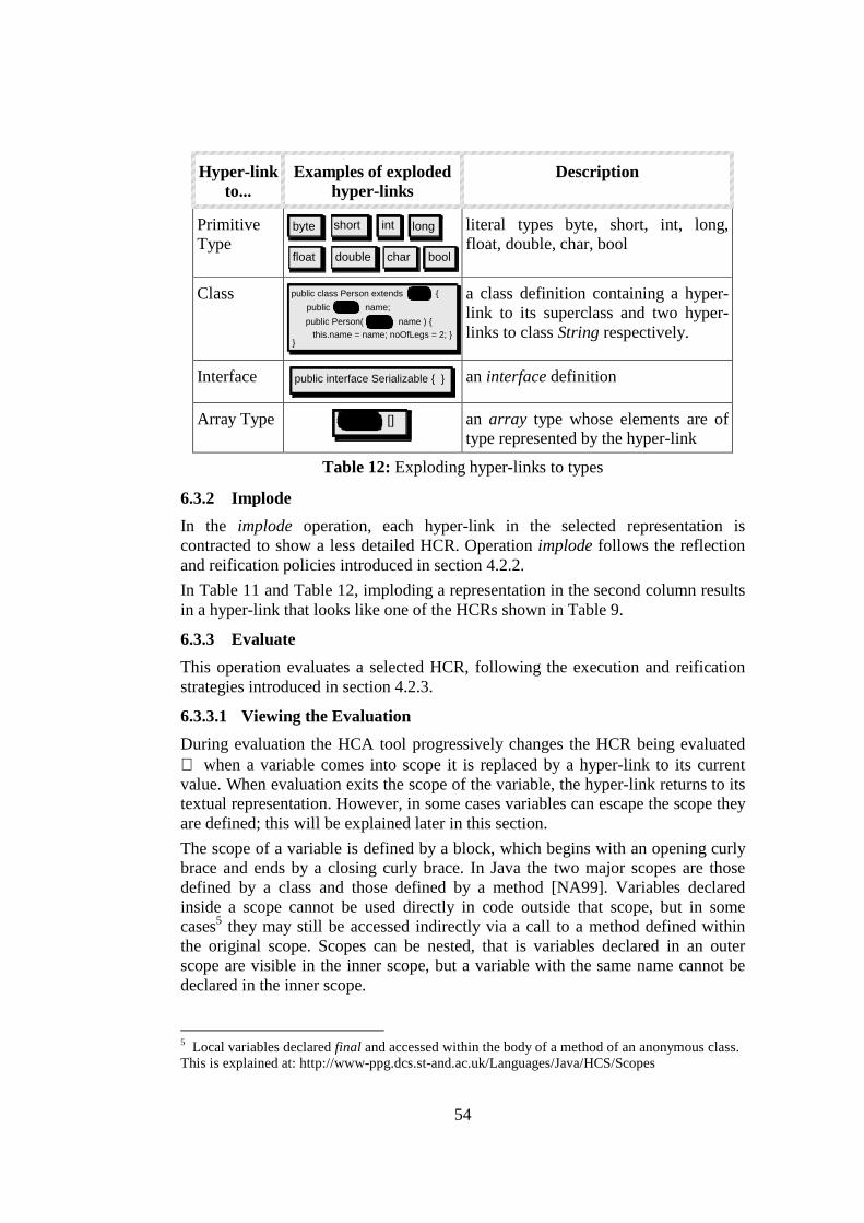
54
Hyper-link to...
Examples of exploded hyper-links
Description
Primitive Type
byte
boolchardoublefloat
longintshort literal types byte, short, int, long, float, double, char, bool
Class public class Person extends {
public name;
}
public Person( name ) {this.name = name; noOfLegs = 2; }
a class definition containing a hyper-link to its superclass and two hyper-links to class String respectively.
Interface public interface Serializable { } an interface definition
Array Type
[]
an array type whose elements are of type represented by the hyper-link
Table 12: Exploding hyper-links to types
6.3.2 Implode In the implode operation, each hyper-link in the selected representation is contracted to show a less detailed HCR. Operation implode follows the reflection and reification policies introduced in section 4.2.2. In Table 11 and Table 12, imploding a representation in the second column results in a hyper-link that looks like one of the HCRs shown in Table 9.
6.3.3 Evaluate This operation evaluates a selected HCR, following the execution and reification strategies introduced in section 4.2.3.
6.3.3.1 Viewing the Evaluation During evaluation the HCA tool progressively changes the HCR being evaluated when a variable comes into scope it is replaced by a hyper-link to its current value. When evaluation exits the scope of the variable, the hyper-link returns to its textual representation. However, in some cases variables can escape the scope they are defined; this will be explained later in this section. The scope of a variable is defined by a block, which begins with an opening curly brace and ends by a closing curly brace. In Java the two major scopes are those defined by a class and those defined by a method [NA99]. Variables declared inside a scope cannot be used directly in code outside that scope, but in some cases5 they may still be accessed indirectly via a call to a method defined within the original scope. Scopes can be nested, that is variables declared in an outer scope are visible in the inner scope, but a variable with the same name cannot be declared in the inner scope.
5 Local variables declared final and accessed within the body of a method of an anonymous class. This is explained at: http://www-ppg.dcs.st-and.ac.uk/Languages/Java/HCS/Scopes
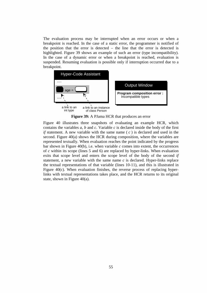
55
The evaluation process may be interrupted when an error occurs or when a breakpoint is reached. In the case of a static error, the programmer is notified of the position that the error is detected – the line that the error is detected is highlighted. Figure 39 shows an example of such an error (type incompatibility). In the case of a dynamic error or when a breakpoint is reached, evaluation is suspended. Resuming evaluation is possible only if interruption occurred due to a breakpoint.
Output Window
Hyper-Code Assistant....
....
age = ;Program composition error : Incompatible types
a link to anint type
a link to an instanceof class Person
Figure 39: A PJama HCR that produces an error Figure 40 illustrates three snapshots of evaluating an example HCR, which contains the variables a, b and c. Variable c is declared inside the body of the first if statement. A new variable with the same name ( c ) is declared and used in the second. Figure 40(a) shows the HCR during composition, where the variables are represented textually. When evaluation reaches the point indicated by the progress bar shown in Figure 40(b), i.e. when variable c comes into extent, the occurrences of c within its scope (lines 5 and 6) are replaced by hyper-links. When evaluation exits that scope level and enters the scope level of the body of the second if statement, a new variable with the same name c is declared. Hyper-links replace the textual representations of that variable (lines 10-11), and this is illustrated in Figure 40(c). When evaluation finishes, the reverse process of replacing hyper-links with textual representations takes place, and the HCR returns to its original state, shown in Figure 40(a).
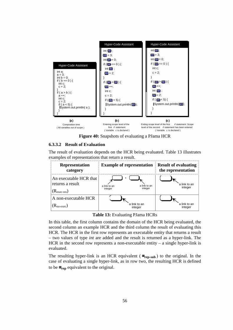
56
Hyper-Code Assistant
int a; a = 3; int b = 0; if ( b == 0 ) { int c; c = 2; }if ( a > b ) { a ++; int c; c = 2; if ( a < 5) { System.out.println( a ); } }
int ; = 3; int = 0; if ( == 0 ) { int ; = 2; }if ( > ) { ++; int c; c = 2; if ( < 5) { System.out.println( ); } }
Hyper-Code Assistant Hyper-Code Assistant
int ; = 3; int = 0; if ( == 0 ) { int c; c = 2; }if ( > ) { ++; int ; = 2; if ( < 5) { System.out.println( ); } }
(a )Composition time
( All variables out of scope )
(b )Entering scope level of the
first if statement ( Variable c is declared )
(c )Exiting scope level of the first if statement. Scopelevel of the second if statement has been entered
( Variable c is declared ) Figure 40: Snapshots of evaluating a PJama HCR
6.3.3.2 Result of Evaluation The result of evaluation depends on the HCR being evaluated. Table 13 illustrates examples of representations that return a result.
Representation category
Example of representation Result of evaluating the representation
An executable HCR that returns a result (Rexec-res)
+
a link to aninteger
a link to aninteger
a link to aninteger
A non-executable HCR (Rno-exec) a link to an
integer a link to an
integer Table 13: Evaluating PJama HCRs
In this table, the first column contains the domain of the HCR being evaluated, the second column an example HCR and the third column the result of evaluating this HCR. The HCR in the first row represents an executable entity that returns a result – two values of type int are added and the result is returned as a hyper-link. The HCR in the second row represents a non-executable entity – a single hyper-link is evaluated.
The resulting hyper-link is an HCR equivalent ( ≡≡≡≡rep-sub ) to the original. In the case of evaluating a single hyper-link, as in row two, the resulting HCR is defined to be ≡≡≡≡rep equivalent to the original.
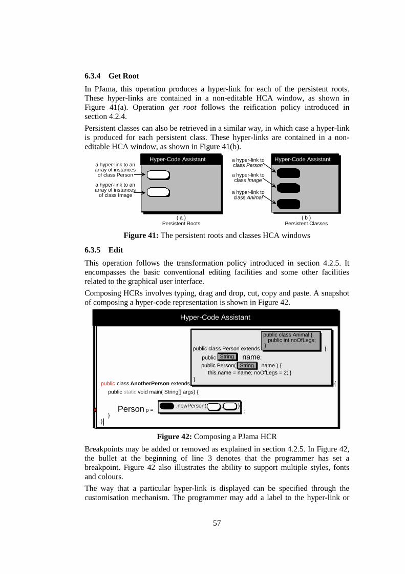
57
6.3.4 Get Root In PJama, this operation produces a hyper-link for each of the persistent roots. These hyper-links are contained in a non-editable HCA window, as shown in Figure 41(a). Operation get root follows the reification policy introduced in section 4.2.4. Persistent classes can also be retrieved in a similar way, in which case a hyper-link is produced for each persistent class. These hyper-links are contained in a non-editable HCA window, as shown in Figure 41(b).
Hyper-Code Assistant
a hyper-link to anarray of instancesof class Person
a hyper-link to anarray of instances
of class Image
Hyper-Code Assistant
a hyper-link toclass Image
a hyper-link toclass Animal
a hyper-link toclass Person
( a ) ( b )Persistent Roots Persistent Classes
Figure 41: The persistent roots and classes HCA windows
6.3.5 Edit This operation follows the transformation policy introduced in section 4.2.5. It encompasses the basic conventional editing facilities and some other facilities related to the graphical user interface. Composing HCRs involves typing, drag and drop, cut, copy and paste. A snapshot of composing a hyper-code representation is shown in Figure 42.
Hyper-Code Assistant
public class AnotherPerson extends {
public class Person extends {public name;
}
public Person( name ) {
public static void main( String[] args) {
Person p =
}}
String
public class Animal {public int noOfLegs;
}
.newPerson( , );
this.name = name; noOfLegs = 2; }String
Figure 42: Composing a PJama HCR
Breakpoints may be added or removed as explained in section 4.2.5. In Figure 42, the bullet at the beginning of line 3 denotes that the programmer has set a breakpoint. Figure 42 also illustrates the ability to support multiple styles, fonts and colours. The way that a particular hyper-link is displayed can be specified through the customisation mechanism. The programmer may add a label to the hyper-link or
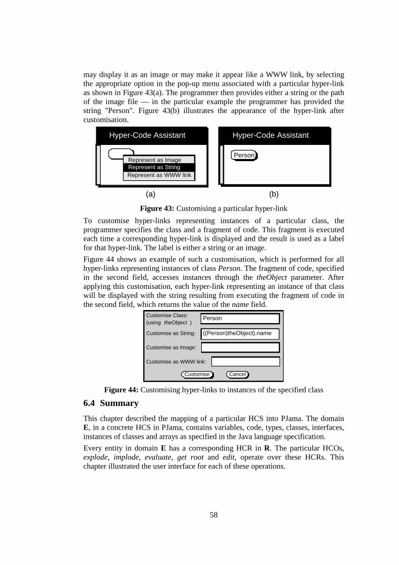
58
may display it as an image or may make it appear like a WWW link, by selecting the appropriate option in the pop-up menu associated with a particular hyper-link as shown in Figure 43(a). The programmer then provides either a string or the path of the image file — in the particular example the programmer has provided the string "Person". Figure 43(b) illustrates the appearance of the hyper-link after customisation.
Hyper-Code Assistant
Represent as ImageRepresent as String
Hyper-Code Assistant
Person
(a) (b)
Represent as WWW link
Figure 43: Customising a particular hyper-link
To customise hyper-links representing instances of a particular class, the programmer specifies the class and a fragment of code. This fragment is executed each time a corresponding hyper-link is displayed and the result is used as a label for that hyper-link. The label is either a string or an image. Figure 44 shows an example of such a customisation, which is performed for all hyper-links representing instances of class Person. The fragment of code, specified in the second field, accesses instances through the theObject parameter. After applying this customisation, each hyper-link representing an instance of that class will be displayed with the string resulting from executing the fragment of code in the second field, which returns the value of the name field.
Customise Class: (using theObject )
Customise as String: ((Person)theObject).name
Customise Cancel
Person
Customise as WWW link:
Customise as Image:
Figure 44: Customising hyper-links to instances of the specified class
6.4 Summary This chapter described the mapping of a particular HCS into PJama. The domain E, in a concrete HCS in PJama, contains variables, code, types, classes, interfaces, instances of classes and arrays as specified in the Java language specification. Every entity in domain E has a corresponding HCR in R. The particular HCOs, explode, implode, evaluate, get root and edit, operate over these HCRs. This chapter illustrated the user interface for each of these operations.
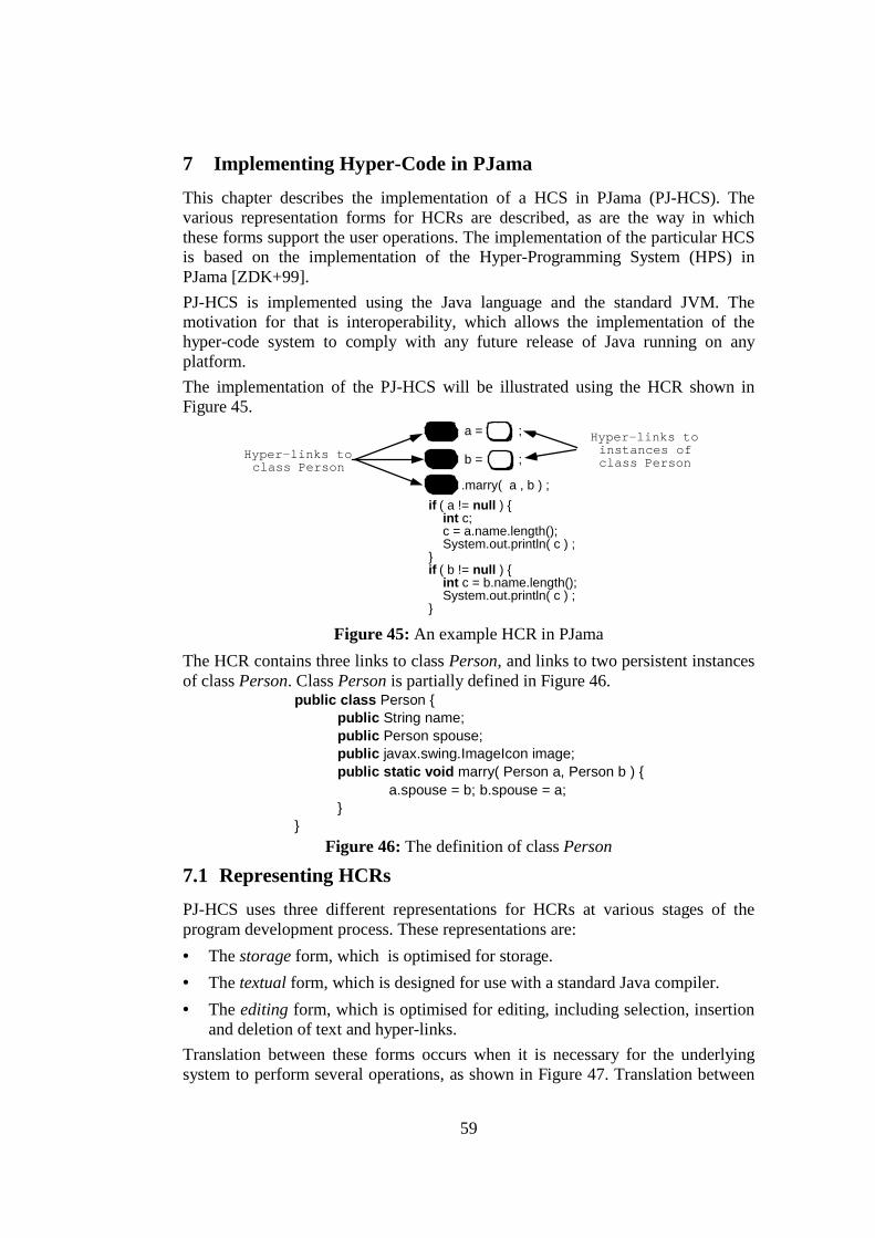
59
7 Implementing Hyper-Code in PJama This chapter describes the implementation of a HCS in PJama (PJ-HCS). The various representation forms for HCRs are described, as are the way in which these forms support the user operations. The implementation of the particular HCS is based on the implementation of the Hyper-Programming System (HPS) in PJama [ZDK+99]. PJ-HCS is implemented using the Java language and the standard JVM. The motivation for that is interoperability, which allows the implementation of the hyper-code system to comply with any future release of Java running on any platform. The implementation of the PJ-HCS will be illustrated using the HCR shown in Figure 45.
Hyper-links toinstances ofclass Person
.marry( a , b ) ;
a = ;
b = ;
if ( a != null ) { int c; c = a.name.length(); System.out.println( c ) ; }if ( b != null ) { int c = b.name.length(); System.out.println( c ) ; }
Hyper-links toclass Person
Figure 45: An example HCR in PJama
The HCR contains three links to class Person, and links to two persistent instances of class Person. Class Person is partially defined in Figure 46.
public class Person { public String name; public Person spouse; public javax.swing.ImageIcon image; public static void marry( Person a, Person b ) { a.spouse = b; b.spouse = a; } }
Figure 46: The definition of class Person
7.1 Representing HCRs PJ-HCS uses three different representations for HCRs at various stages of the program development process. These representations are: • The storage form, which is optimised for storage. • The textual form, which is designed for use with a standard Java compiler. • The editing form, which is optimised for editing, including selection, insertion
and deletion of text and hyper-links. Translation between these forms occurs when it is necessary for the underlying system to perform several operations, as shown in Figure 47. Translation between

60
the editing form and the storage form, and vice versa, takes place when the HCA saves or loads a HCR in/from the persistent store respectively. The textual form is generated from the storage form during the evaluation process, as will be explained in the next section. Finally, files containing purely textual program fragments may be loaded from an external file system and transformed into the HCA editing form.
Editing Storage
Textual
load
save
generatetextual form
generateediting form
Figure 47: Transforming between the three HCR forms
7.2 Implementation of the Evaluation Process The evaluate operation, behind the scenes, performs all the standard operations included in the traditional programming life cycle, that is pre-processing, compiling, executing and returning a result (if any). This is illustrated in Figure 48. If the HCR represents a primitive type, an array type or a class name then compilation and execution are unnecessary and evaluation produces a single hyper-link as explained in section 7.2.6. Otherwise, the system generates a new program fragment in the form of source code, invokes a dynamically callable compiler, and finally links the result of the compilation into its own execution. For the rest of the chapter, it will be assumed that the HCR to be evaluated does not represent a primitive type or array type or a class name. In order to compile an HCR, it must first be translated into a valid Java program, which is a purely textual class definition. This is defined in the Java Language Specification [GJS96] as the CompilationUnit syntactic production. This transformation, which is performed during the pre-processing stage, is required in order to use standard Java compilers.

61
true
false
transform compile
execute
execute?
result?
is HCRprimitive type or
array type orclass name?
produce ahyper-link
for the entity
text
yes
yes
no
no
class
Start Stop
HCR
Figure 48: The evaluation algorithm
The transformation is illustrated in Figure 49. It involves the following tasks: • The storage form of the HCR is wrapped up in a class definition, only if
necessary, producing a new HCR in storage form. • This is then transformed into the textual form, which contains textual
denotations representing the hyper-links. • Some additional program fragments are then inserted, in order to achieve
breakpoint manipulation and variable tracking. The resulting textual class definition is then ready for compilation.
class {
}
class {
}
class {
}
wrapping generatetextual form
variabletracking
fragment class class class
classready for
compilation
storage form textual form Figure 49: Transforming storage form into textual form
The following sections describe the storage form data structure of an HCR and how this form is used for the various stages of evaluation.
7.2.1 The Storage Form The storage form stores the textual part of the HCR as a string, and the hyper-links in a vector. Figure 50 shows the storage form of the example HCR.

62
"Y"
15
false
false
"X"
6
false
false
" a = ;b = ;.marry(a,b);
if (a!=null) {int c;c=a.name.length();System.out.println(c);
}if (b!=null) {
int c=b.name.length();System.out.println(c);
}"vector of hyper-links
label for hyper-link
position of hyper-linkin the string
boolean denoting whetherhyper-link denotes a classor methodboolean denoting whetherhyper-link denotes aprimitive value
StorageForm
"Person"
9
true
false
Classinstance
Personinstance
Personinstance
StorageFormHL
"Person"
18
true
false
"Person"
0
true
false
StorageFormHL
textual part of HCR
Figure 50: An instance of the storage form
The storage form is represented by the class StorageForm, which is shown in Figure 51. Each instance contains a string and a vector of StorageFormHL instances. The string contains the textual part of the HCR, while the vector contains references to the hyper-linked entities. An instance of class StorageForm can be transformed into its textual form through method generateTextualForm. As will be explained later in detail, this method replaces each hyper-link with an expression that will retrieve the hyper-linked entity from the persistent store. This expression contains a call to method getLink.
public class StorageForm { protected String theText; // The textual part of the HCR protected Vector theLinks; // A vector of StorageFormHL instances public StorageForm () { … } public StorageForm (String theText) { … } public StorageForm (String theText, Vector theLinks) { … } // Other constructors // Methods for retrieving and updating the fields public String generateTextualForm() { … } public static getLink( int passwd, int hcr, int hl ) { … } }
Figure 51: The definition of class StorageForm The class StorageFormHL is defined in Figure 52. The entityObject field stores either an object or an instance of class Class. The isClass field is used to distinguish between object and represented class. The isPrimitive field is used to distinguish between a primitive value and an instance of a class. The position field denotes the position of the hyper-link in the HCR.

63
public class StorageFormHL implements EntityRepresentation { protected Object entityObject; protected boolean isClass; protected boolean isPrimitive; protected int position; // Other declarations and initialisations public StorageFormHL(Object entityObject, boolean isClass,
boolean isPrimitive, int position) { … } // Other constructors // Methods for retrieving and updating the fields // Other methods
}
Figure 52: The definition of class StorageFormHL Class StorageFormHL implements the EntityRepresentation interface, defined in Figure 53. This interface contains methods for retrieving and updating a set of values representing an entity. In class StorageFormHL, these values are included in the protected fields entityObject, isClass and isPrimitive.
public interface EntityRepresentation { public void setEntityObject(Object anObject); public Object getEntityObject(); public void setEntityClassBool(boolean classBool); public boolean getEntityClassBool(); public void setEntityPrimBool(boolean primBool); public boolean getEntityPrimBool();
}
Figure 53: The definition of interface EntityRepresentation The use of the fields in class StorageFormHL depends on the represented entity. In the example, for the link to the class Person, the entityObject field refers to an instance of class Class representing class Person. For a link to an instance of class Person, the entityObject field refers to that instance. Table 14 shows the use of the StorageFormHL fields for each category of entity that can be hyper-linked. In row 3, distinction between a class and an interface is achieved by invoking method Class.isInterface on the class of the entityObject field. Similarly, in row 5, distinction between an array and a non-array instance is achieved by invoking method Class.isArray on the class of the entityObject field. In the case of a variable, the hyper-link represents its current value, that is one of the entities in rows 4 and 5. In the case of code, there is no set of values to store the relevant information, as code cannot be represented by a single hyper-link.
Entity entityObject isClass isPrimitive
primitive type
instance of class Classwrapping the primitive type
true true
array type instance of class Classrepresenting the array type
true false
class or interface
instance of class Classrepresenting the class or i f
true false
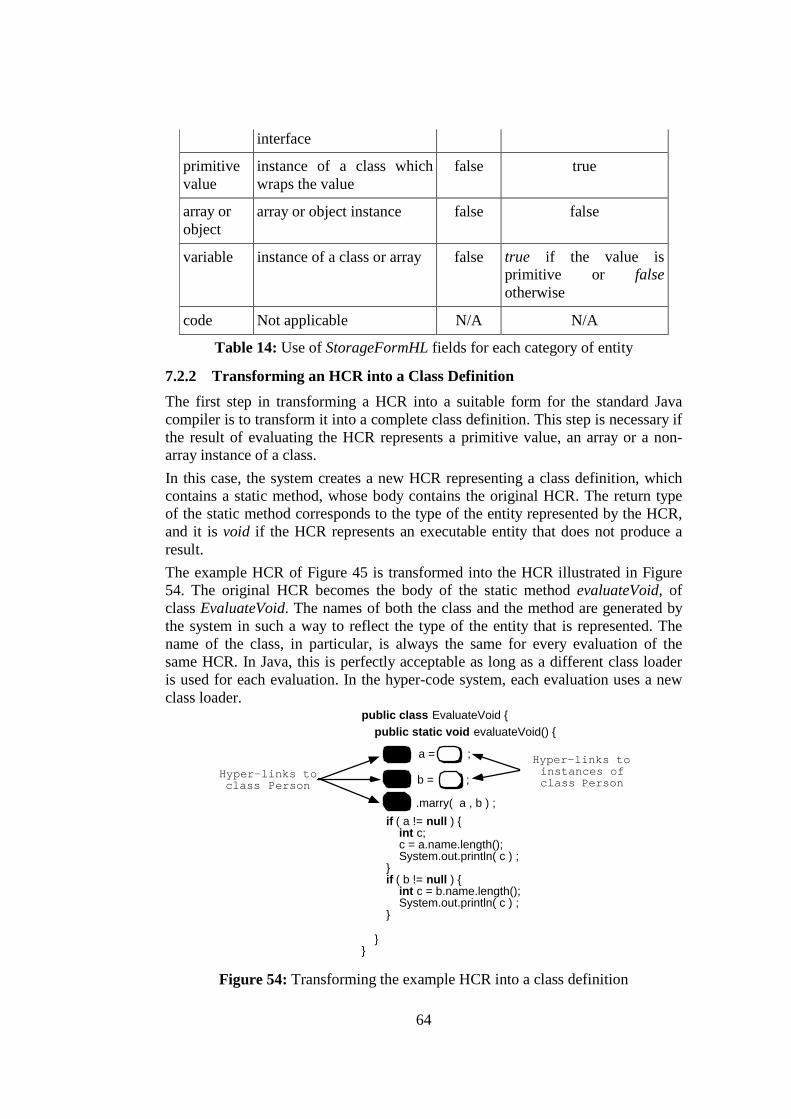
64
interface
primitive value
instance of a class which wraps the value
false true
array or object
array or object instance false false
variable instance of a class or array false true if the value is primitive or falseotherwise
code Not applicable N/A N/A
Table 14: Use of StorageFormHL fields for each category of entity
7.2.2 Transforming an HCR into a Class Definition The first step in transforming a HCR into a suitable form for the standard Java compiler is to transform it into a complete class definition. This step is necessary if the result of evaluating the HCR represents a primitive value, an array or a non-array instance of a class. In this case, the system creates a new HCR representing a class definition, which contains a static method, whose body contains the original HCR. The return type of the static method corresponds to the type of the entity represented by the HCR, and it is void if the HCR represents an executable entity that does not produce a result. The example HCR of Figure 45 is transformed into the HCR illustrated in Figure 54. The original HCR becomes the body of the static method evaluateVoid, of class EvaluateVoid. The names of both the class and the method are generated by the system in such a way to reflect the type of the entity that is represented. The name of the class, in particular, is always the same for every evaluation of the same HCR. In Java, this is perfectly acceptable as long as a different class loader is used for each evaluation. In the hyper-code system, each evaluation uses a new class loader.
public class EvaluateVoid { public static void evaluateVoid() {
Hyper-links toinstances ofclass Person
.marry( a , b ) ;
a = ;
b = ;
if ( a != null ) { int c; c = a.name.length(); System.out.println( c ) ; }if ( b != null ) { int c = b.name.length(); System.out.println( c ) ; }
Hyper-links toclass Person
} }
Figure 54: Transforming the example HCR into a class definition
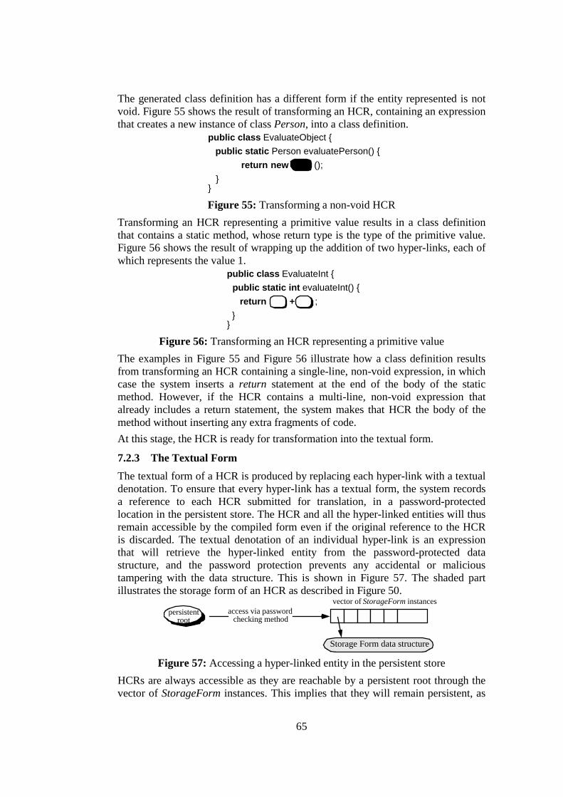
65
The generated class definition has a different form if the entity represented is not void. Figure 55 shows the result of transforming an HCR, containing an expression that creates a new instance of class Person, into a class definition.
public class EvaluateObject { public static Person evaluatePerson() {
return new (); } } Figure 55: Transforming a non-void HCR
Transforming an HCR representing a primitive value results in a class definition that contains a static method, whose return type is the type of the primitive value. Figure 56 shows the result of wrapping up the addition of two hyper-links, each of which represents the value 1.
public class EvaluateInt { public static int evaluateInt() { return + ; } }
Figure 56: Transforming an HCR representing a primitive value The examples in Figure 55 and Figure 56 illustrate how a class definition results from transforming an HCR containing a single-line, non-void expression, in which case the system inserts a return statement at the end of the body of the static method. However, if the HCR contains a multi-line, non-void expression that already includes a return statement, the system makes that HCR the body of the method without inserting any extra fragments of code. At this stage, the HCR is ready for transformation into the textual form.
7.2.3 The Textual Form The textual form of a HCR is produced by replacing each hyper-link with a textual denotation. To ensure that every hyper-link has a textual form, the system records a reference to each HCR submitted for translation, in a password-protected location in the persistent store. The HCR and all the hyper-linked entities will thus remain accessible by the compiled form even if the original reference to the HCR is discarded. The textual denotation of an individual hyper-link is an expression that will retrieve the hyper-linked entity from the password-protected data structure, and the password protection prevents any accidental or malicious tampering with the data structure. This is shown in Figure 57. The shaded part illustrates the storage form of an HCR as described in Figure 50.
access via passwordchecking method
persistentroot
vector of StorageForm instances
Storage Form data structure Figure 57: Accessing a hyper-linked entity in the persistent store
HCRs are always accessible as they are reachable by a persistent root through the vector of StorageForm instances. This implies that they will remain persistent, as

66
there is always a reference from that vector. Therefore, to enable these instances to be garbage collected, the system periodically removes the references to those StorageForm instances that do not have a corresponding persistent class associated with them. The corresponding class is the class resulting from transforming, compiling and loading the original HCR. The association between an HCR and its corresponding class is achieved using a hashtable of weak references (class java.util.WeakHashMap, provided in the standard JDK 2) and a vector containing HCRs. The hashtable is used to store the corresponding class as key and the index of the original HCR in the HCRs vector as value. The use of WeakReferences ensures that the class will be garbage collected, if it is not made persistent. The system then removes, from the vector of StorageForm instances, those HCRs that do not have an associated class as the key in the hashtable. After ensuring that there will always be an access path for each hyper-linked entity, the textual form of a HCR is generated by the method StorageForm.generateTextualForm. A textual equivalent is generated for each hyper-link. For example, the textual equivalent for a hyper-link representing a primitive value is the value itself converted into a string. This expression has the form:
<StorageFormHL instance>.getEntityObject().toString() The textual representation of a hyper-link to a class, interface or primitive type is obtained by an expression which retrieves the hyper-linked entity, that is the class or interface, and obtains its name. This expression has the following form:
( (Class)< StorageFormHL instance >.getEntityObject() ).getName() The textual representation of a hyper-link to an array type is obtained by an expression which retrieves the name of the component type, as explained before, and adds the "[]" at the end. This expression has the following form:
( (Class)< StorageForm instance > .getEntityObject()).getComponentType().getName()+"[]"
The textual representation of a hyper-link to an object includes a unique id allocated to each HCR when it is processed, and the index of the hyper-link within the HCR. This has the form:
((class name) StorageForm.getLink( secret password,
unique id for HCR,
unique id for hyper-link).getObject() )
The static method StorageForm.getLink retrieves a specified StorageFormHL instance from the persistent data structure of Figure 57, taking as parameters the password and indices for the HCR and the hyper-link. The call to the getObject method returns the hyper-linked object itself, which is then cast to its specific class. The entire expression thus gives an access path to the hyper-linked object that may be evaluated correctly at run-time. Figure 58 shows the resulting textual form for the example HCR of Figure 45. The hyper-link textual equivalents in lines 5-7 are generated as follows:
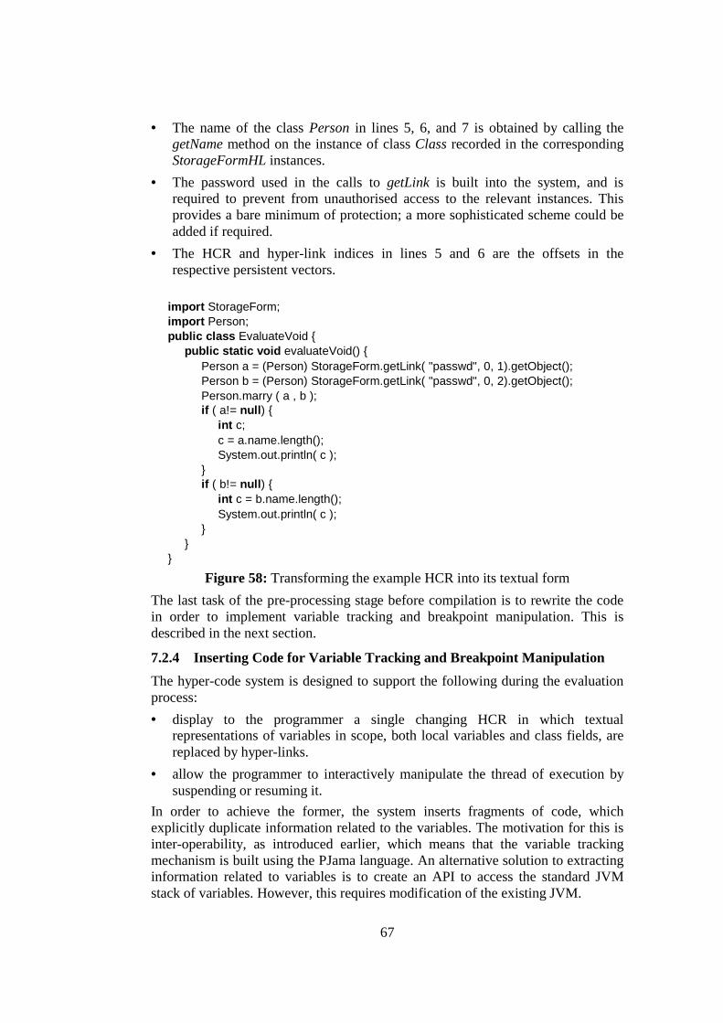
67
• The name of the class Person in lines 5, 6, and 7 is obtained by calling the getName method on the instance of class Class recorded in the corresponding StorageFormHL instances.
• The password used in the calls to getLink is built into the system, and is required to prevent from unauthorised access to the relevant instances. This provides a bare minimum of protection; a more sophisticated scheme could be added if required.
• The HCR and hyper-link indices in lines 5 and 6 are the offsets in the respective persistent vectors.
import StorageForm; import Person; public class EvaluateVoid {
public static void evaluateVoid() { Person a = (Person) StorageForm.getLink( "passwd", 0, 1).getObject(); Person b = (Person) StorageForm.getLink( "passwd", 0, 2).getObject(); Person.marry ( a , b ); if ( a!= null) {
int c; c = a.name.length(); System.out.println( c );
} if ( b!= null) {
int c = b.name.length(); System.out.println( c );
} }
}
Figure 58: Transforming the example HCR into its textual form The last task of the pre-processing stage before compilation is to rewrite the code in order to implement variable tracking and breakpoint manipulation. This is described in the next section.
7.2.4 Inserting Code for Variable Tracking and Breakpoint Manipulation The hyper-code system is designed to support the following during the evaluation process: • display to the programmer a single changing HCR in which textual
representations of variables in scope, both local variables and class fields, are replaced by hyper-links.
• allow the programmer to interactively manipulate the thread of execution by suspending or resuming it.
In order to achieve the former, the system inserts fragments of code, which explicitly duplicate information related to the variables. The motivation for this is inter-operability, as introduced earlier, which means that the variable tracking mechanism is built using the PJama language. An alternative solution to extracting information related to variables is to create an API to access the standard JVM stack of variables. However, this requires modification of the existing JVM.
68
In order to achieve the latter, that is to allow the interactive manipulation of the thread of execution, the system inserts fragments of code to suspend execution and transfer control to the programmer. This involves resuming or killing of the thread of execution.
7.2.4.1 Requirements for the Inserted Code The inserted fragments of code perform operations required to achieve the following: • Keep track of local variables when they are declared. • Keep track of fields of a class on entering the scope level of the body of a
method. • Keep track of the value of variables when assignment is performed. • Remove the information related to variables when they leave scope. • Trigger the redrawing of the HCR in the HCA when any of the above
operations is performed. • Keep track of the current execution line for display to the programmer when
interruption due to an error or a breakpoint occurs. • Suspend the thread of execution on reaching breakpoints.
7.2.4.2 Meeting the Requirements - The Thread of Execution The thread of execution and the data structure for variable tracking are stored in instances of class HyperCodeThread, partially defined in Figure 59. The thread is created and manipulated by the hyper-code system, after compilation and loading of the transformed class definition, and this will be explained later in section 7.2.5. Each instance of class HyperCodeThread is associated with a particular execution of an HCR. During the code transformation stage of the evaluation process, the system adds fragments of code to retrieve the current thread of execution and suspend it, when a breakpoint is detected.
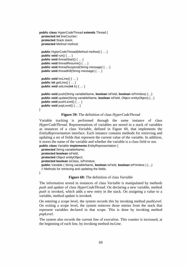
69
public class HyperCodeThread extends Thread { protected int lineCounter; protected Stack stack; protected Method method; public HyperCodeThread(Method method) { … } public void run() { … } public void threadStart() { … } public void threadResume() { … } public void threadSuspend(String message) { … } public void threadKill(String message) { … } public void incLine() { … } public int getLine() { … } public void setLine(int lc) { … } public void push(String variableName, boolean isField, boolean isPrimitive) {…} public void update(String variableName, boolean isField, Object entityObject) {…} public void pushLevel() { … } public void popLevel() { … }
}
Figure 59: The definition of class HyperCodeThread Variable tracking is performed through the same instance of class HyperCodeThread. Representations of variables are stored in a stack of variables as instances of a class Variable, defined in Figure 60, that implements the EntityRepresentation interface. Each instance contains methods for retrieving and updating a set of fields that represent the current value of the variable. In addition, it stores the name of the variable and whether the variable is a class field or not. public class Variable implements EntityRepresentation {
protected String variableName; protected boolean isField; protected Object entityObject; protected boolean isClass, isPrimitive; public Variable ( String variableName, boolean isField, boolean isPrimitive ) {…} // Methods for retrieving and updating the fields.
} Figure 60: The definition of class Variable
The information stored in instances of class Variable is manipulated by methods push and update of class HyperCodeThread. On declaring a new variable, method push is invoked, which adds a new entry in the stack. On assigning a value to a variable, method update is invoked. On entering a scope level, the system records this by invoking method pushLevel. On exiting a scope level, the system removes those entries from the stack that represent variables declared in that scope. This is done by invoking method popLevel. The system also records the current line of execution. This counter is increased, at the beginning of each line, by invoking method incLine.

70
Updating the HCR displayed in the HCA is required when assigning a value to a variable or when exiting a scope. This is done through methods update, and popLevel. These methods, which are called by the newly generated programs, invoke the updateHCR method of class WindowEditor, defined in a later section. The method takes the stack of variables as parameter, and updates the HCR displayed in the HCA window by replacing the textual representations of the variables included in the stack with hyper-links.
7.2.4.3 Transforming the Example HCR The example textual form illustrated in Figure 58, after inserting the appropriate fragments of code, is transformed to the class definition shown in Figure 61. It is assumed that the programmer has inserted a breakpoint at the beginning of line 4 of the example HCR shown in Figure 45. The textual form of the HCR resulting from the stage of evaluation described in the previous section is underlined, in order to emphasise the fragments of code inserted for variable tracking and thread manipulation. import HyperCodeThread; import StorageForm; import Person; public class EvaluateVoidExpression {
public static void evaluateVoid() { // Record the current thread of execution HyperCodeThread t = (HyperCodeThread)Thread.currentThread(); // Increase the scope level counter, as a new scope level is created t.pushLevel(); t.incLine(); Person a = (Person)StorageForm.getLink("passwd",0,1).getObject()); //Push variable "a" on the stack and update its value t.push("a", false, false); t.update("a", false, a); t.incLine();
Person b = (Person)StorageForm.getLink("passwd",0,2).getObject()); //Push variable "b" on the stack and update its value t.push("b", false, false); t.update("b", false, b); t.incLine(); Person.marry(a, b); // Trigger the suspension of the current thread of execution t.threadSuspend("Breakpoint at line "+t.getLine()); // No declaration, assignment of breakpoints. Just increase the line number t.incLine(); if (a!=null) { t.pushLevel(); t.incLine(); int c; t.push("c", false, true); // Push variable "c" on the stack // Update the value of variable "c" t.incLine(); c = a.name.length(); t.update("c", false, new Integer(c)); t.incLine(); System.out.println(c); t.popLevel();// Remove variable "c" from the stack t.incLine(); } t.incLine(); if (b!=null) { t.pushLevel(); //Push variable "c" on the stack and update its value t.incLine(); int c = b.name.length();
t.push("c", false, true); t.update("c", false, new Integer(c)); t.incLine(); System.out.println(c); t.popLevel();// Remove variable "c" from the stack t.incLine(); }

71
t.popLevel(); // Remove variables "a" and "b" from the stack }
}
Figure 61: The result of transforming the example HCR
7.2.4.4 Transforming an Example HCR Representing a Class Definition The example of Figure 61 illustrated how local variables are pushed and popped to/from the stack respectively. However, in the case of an HCR defining a class that contains several fields, transformation involves tracking of those fields. When a method is invoked, these fields are considered global variables, contained in the scope level 0. Thus, the system inserts fragments of code to push them onto the stack at the beginning of the method.
public class X { static String message = "The value of the integer is: "; int theInt = 2; public void printTheValueOut() {
System.out.println(message+theInt); }
}
Figure 62: An example class definition To illustrate this, the class definition shown in Figure 62 is used as an example. The class contains two fields and a method that prints out the value of the second field. Figure 63 shows the class definition after inserting the appropriate fragments of code, where the original HCR is underlined. The method initially retrieves the current thread of execution, and sets the line counter to 4, that is the number of lines, in the original HCR, up to the first line of the method to be executed. The fields of the class are then pushed on the stack and their values are updated accordingly. The second parameter of both the methods push and update is true, denoting that the variable is a field of a class, rather than local in the execution of the method. Just before the execution of the method terminates, variables "message" and "theInt" are removed from the stack. On every invocation of the method, these fields are pushed on the stack before any other local variable, since they are global.
import HyperCodeThread; public class X {
static String message = "The value of the integer is: "; int theInt = 2; public void printTheValueOut() {
HyperCodeThread t = (HyperCodeThread)Thread.currentThread(); t.setLine(4); // Increase the scope level counter. t.pushLevel(); //Push static field "message" and update its value t.push("message", true, false); t.update("message", true, X.message); //Push field "theInt" and update its value t.push("theInt", true, true); t.update("theInt", true, new Integer(theInt)); t.incLine(); System.out.println(message+theInt); // Increment the line counter t.popLevel(); // Remove variables "message" and "theInt" from the stack

72
} }
Figure 63: Transforming the example class definition of Figure 62
7.2.5 Compiling and Executing HCRs
7.2.5.1 Compiling and Loading Class Definitions The result of transformation is a purely textual class definition, which contains access paths to the hyper-linked entities and additional fragments of code for variable tracking and thread manipulation. This form is suitable for compilation using a compiler that dynamically translates the textual form into a sequence of byte code, and then loads a class using a ClassLoader. In order to achieve both the tasks the system uses the Dynamic Compiler, which provides linguistic reflection facilities to standard Java [KMS98], since the Java environment only provides facilities for introspection and not for dynamic compilation. Figure 64 shows several compilation methods provided by the class DynamicCompiler. public class DynamicCompiler {
public DynamicCompiler() { … } public Class compileClass( String defn) throws CompilationException {…} public Class[] compileClasses (String[] defns) throws CompilationException { …} // Other methods
} Figure 64: The definition of class DynamicCompiler
The main compilation method is compileClasses, which takes an array of source code strings defining a number of classes and attempts to compile them by invoking the standard Java compiler directly as a Java class. If this fails, then a new operating system process is started to call the Java compiler. If the compilation is successful, the result is an array of instances of class Class, otherwise an exception is thrown. The first mechanism has the advantage of fewer run-time overheads. The disadvantage is the reliance on knowledge of the Java implementation, in particular of the compiler interface and of which package contains the compiler. Thus a change in the Java implementation — such as placing the compiler in a different package or re-implementation of the compiler in a different language — would prevent this approach from working. The disadvantages of the second mechanism are that significant additional run-time resources are involved in creating a new instantiation of the JVM and that it is more platform-specific. Dynamic compilation, if successful, creates class definitions in the form of byte code sequences (.class files). To be useful these must then be loaded into the running system and converted to instances of class Class. This is achieved using a subclass of class Classloader − details are given in [KMS98].
7.2.5.2 Executing Methods The processes described in the previous sections involved the following tasks: • An HCR is transformed into a class definition (if necessary).

73
• Since the class definition may contain hyper-links, it is transformed into a purely textual Java class definition.
• Additional fragments of code are inserted for variable tracking and breakpoint manipulation.
• After transforming, the class definition is compiled and loaded. • Once a class has been loaded at run-time, it is available for use. At this stage
execution may take place and this involves invocation of the method included in the instance of class Class resulting from compilation and loading. For the example HCR, illustrated in Figure 54, this implies that method EvaluateVoid.evaluateVoid is invoked.
Execution takes place if the original HCR represents any void or non-void expression that is not a class or interface definition. If execution is required, the static method of the class resulting from compilation and loading is invoked using the standard Java reflection package. Each invocation of a method is associated with a particular Java thread and is performed through it. A Java thread is an instance of a class that extends class java.lang.Thread. The extending class must override the run method, which is the entry point for the new thread. It must also call start to begin execution of the new thread. Class HyperCodeThread extends class Thread. A new thread is created and started by instantiating the extending class and calling method threadStart. The expression to achieve that has the form shown in Figure 65, where the method passed as parameter to the constructor is the static method included in the generated class. This Method instance is stored in the method field of the newly created instance of class HyperCodeThread.
HyperCodeThread t = new HyperCodeThread( <Method instance to be invoked> ); t.threadStart();
Figure 65: Initialising and starting a thread The invocation of the method, passed to the constructor, takes place in the body of method HyperCodeThread.run, which is called when a thread starts. The expression to invoke a method is shown in Figure 66, where the Method instance is the value of the relevant field of class HyperCodeThread.
try { Object o = <Method instance to be invoked>.invoke(null, new String[0]); } catch (Exception ex) { threadKill("Exception "+ex.getMessage()+" occurred at line "+getLine()); } catch (Error er) { threadKill("Internal error "+er.getMessage()+" occurred at line "+getLine()); }
Figure 66: Code in the body of the run method The invocation of the relevant method is included in a try-catch statement, in order to catch any exceptions or errors. An Exception is thrown when a run-time error occurs in executing the body of the method, such as division by zero. An Error is thrown when an error related to the JVM occurs, such as lack of memory. In both the cases, method threadKill is invoked and execution is terminated.
74
If there is no interruption, the body of the invoked method will be executed and the result (if any) is returned as a hyper-link, as will be described later.
7.2.5.3 Compiling and Executing the Example HCR This section describes the process of compiling and executing HCRs using the example class definition of Figure 61. Compilation results in the creation of a file EvaluateVoidExpression.class. The class returned is then loaded, and a new thread is initialised and started using the following expression:
Class aClass = <Instance of class Class resulting from compilation>; Method m = aClass.getMethod("evaluateVoid", null); HyperCodeThread t = new HyperCodeThread( m ); t.threadStart();
Figure 67: Starting a thread for executing the evaluateVoid method This expression triggers the invocation of method evaluateVoid, which occurs in the body of method run, as shown in Figure 68. Note that the variable method is the field that stores the instance of class Method associated with the particular thread of execution.
try { Object o = method.invoke(null, new String[0]); } catch …
Figure 68: Invoking method evaluateVoid inside method run Since a call to threadSuspend is included in the body of method evaluateVoid, the thread of execution is suspended and remains in that state until the programmer resumes it.
7.2.6 Producing a new HCR If execution produces a result, this is returned as a hyper-link in a HCA window and is manipulated by the programmer accordingly. The hyper-link represents the entity that is returned from execution. As an example, evaluating the HCR included in the body of method EvaluateInt.evaluateInt shown in Figure 56 results in a single hyper-link representing the integer two.
7.3 Summary This chapter discusses the principal implementation issues of a particular implementation of a HCS in PJama (PJ-HCS). The system is implemented on top of the existing PJama language and JVM. The motivation for this approach is interoperability, which allows the implementation of the hyper-code system to comply with any future release of PJama and Java running on any platform. The HCR is not a suitable form for the standard Java compiler. Thus transformation between various forms is introduced. These forms are: • the storage form, which is optimised for storage. • the textual form, which is designed for use with a standard Java compiler. • the editing form, which is optimised for editing. The evaluate process performs the following operations:
75
• transformation of the storage form of a HCR into the textual form. This involves: wrapping up the HCR into a class definition, generating the textual form and inserting code for variable tracking and breakpoint manipulation, which is required in order to display to the programmer a changing HCR, and provide debugging.
• compilation and loading of the resulting class definition. • execution, if necessary, and • creation of a new HCR, if required. The next chapter discusses implementation issues related to the Hyper-Code Assistant tool and to operation explode.

76
8 Implementing the Hyper-Code Assistant Tool in PJama The Hyper-Code Assistant (HCA) tool is used to compose and evaluate HCRs. It supports exploding and imploding of hyper-links, embedded hyper-links, basic editing facilities, drag and drop of HCRs, multiple fonts, styles and colours. It performs as a normal editor, but it does not support justification or wrap-around. The HCA tool implementation is structured using three layers, as shown in Figure 69, which allows implementations of different logical components to be changed independently.
Window Editor
Basic Editor
Hyper-CodeUser Editor
Alternativeimplementationof User Editor
Alternativeimplementationof User Editor
Figure 69: The layers implementing the HCA
The Basic Editor (BE) stores and manipulates the editing form and supports the manipulation of the HCR data structure. The Window Editor (WE) supports the graphical display and editing of the HCR, and this involves the manipulation of multiple fonts, styles, sizes and colours. The User Editors (UE) are high-level tools built on top of the WE. One of these tools is the hyper-code UE, which implements the hyper-code concepts.
8.1 The Basic Editor The BE contains the data structure used for storing an HCR. The data structure is the editing form which is similar to the storage form. In the editing form, the textual part of each program line is stored in a separate string. The position of each hyper-link is defined by its offset in the line. This design is optimised for the common editing operations, as their application does not affect the whole data structure, but usually only a small part of it. Figure 70 shows the editing form data structure for the example of Figure 45. For each line, represented by an instance of class HyperLine, the data structure contains the textual part and a vector of hyper-links. The vector of hyper-links contained in the first line includes one to an instance of class Class and one to an instance of class Person. Similarly, the vectors included in the other hyper-lines contain hyper-links to other entities as shown in the figure. Hyper-links are represented by instances of class HyperLink, which is defined later in section 8.2. Similarly to class StorageFormHL, class HyperLink implements the EntityRepresentation interface.

77
vector ofHyperLineinstances
HyperLine" a = ;"
6
false
false
6
false
false
vector ofHyperLinkinstances
other fields, including thelabel of the hyper-link
position of hyper-linkin the line
boolean denoting whetherhyper-link denotes a classor methodboolean denoting whetherhyper-link denotes aprimitive value
0
true
false
Classinstance
Personinstance
Personinstance
0
true
false
0
true
false
EntityRepresentation" b = ;"
" .marry ( a , b );"
"if (a!=null) {"
" int c;"
" c=a.name.length();"
" System.out.println(c);"
"}"
"if (b!=null) {"
" int c=a.name.length();"
"}"
" System.out.println(c);"
... ...
......
...
EntityRepresentation
EntityRepresentation EntityRepresentation
EntityRepresentation
vector ofHyperLinkinstances
Figure 70: The editing form data structure
Class BasicEditor, which is shown in Figure 71, defines the editing form and implements the BE layer. Translation between the editing and the storage form and vice versa is performed through methods importHCR and exportHCR respectively. Methods for editing, navigating and searching within the data structure are also included.
class BasicEditor { protected Vector theLines; // Other fields BasicEditor() { … } // Other constructors public void importHCR( StorageForm hcr ) { … } public StorageForm exportHCR() { … } // Methods for retrieving or updating the fields // Methods for cut, copy, paste, insert and delete // Methods for navigating and searching within the data structure // Other methods
}
Figure 71: The definition of class BasicEditor
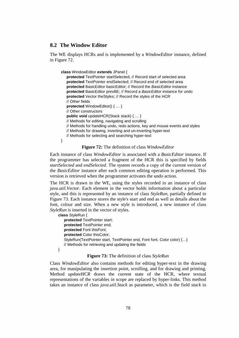
78
8.2 The Window Editor The WE displays HCRs and is implemented by a WindowEditor instance, defined in Figure 72.
class WindowEditor extends JPanel { protected TextPointer startSelected; // Record start of selected area protected TextPointer endSelected; // Record end of selected area protected BasicEditor basicEditor; // Record the BasicEditor instance protected BasicEditor prevBE; // Record a BasicEditor instance for undo protected Vector theStyles; // Record the styles of the HCR // Other fields protected WindowEditor() { … } // Other constructors public void updateHCR(Stack stack) { … } // Methods for editing, navigating and scrolling // Methods for handling undo, redo actions, key and mouse events and styles // Methods for drawing, inverting and un-inverting hyper-text // Methods for selecting and searching hyper-text
}
Figure 72: The definition of class WindowEditor Each instance of class WindowEditor is associated with a BasicEditor instance. If the programmer has selected a fragment of the HCR this is specified by fields startSelected and endSelected. The system records a copy of the current version of the BasicEditor instance after each common editing operation is performed. This version is retrieved when the programmer activates the undo action. The HCR is drawn in the WE, using the styles recorded in an instance of class java.util.Vector. Each element in the vector holds information about a particular style, and this is represented by an instance of class StyleRun, partially defined in Figure 73. Each instance stores the style's start and end as well as details about the font, colour and size. When a new style is introduced, a new instance of class StyleRun is inserted in the vector of styles.
class StyleRun { protected TextPointer start; protected TextPointer end; protected Font thisFont; protected Color thisColor; StyleRun(TextPointer start, TextPointer end, Font font, Color color) {…} // Methods for retrieving and updating the fields }
Figure 73: The definition of class StyleRun Class WindowEditor also contains methods for editing hyper-text in the drawing area, for manipulating the insertion point, scrolling, and for drawing and printing. Method updateHCR draws the current state of the HCR, where textual representations of the variables in scope are replaced by hyper-links. This method takes an instance of class java.util.Stack as parameter, which is the field stack in
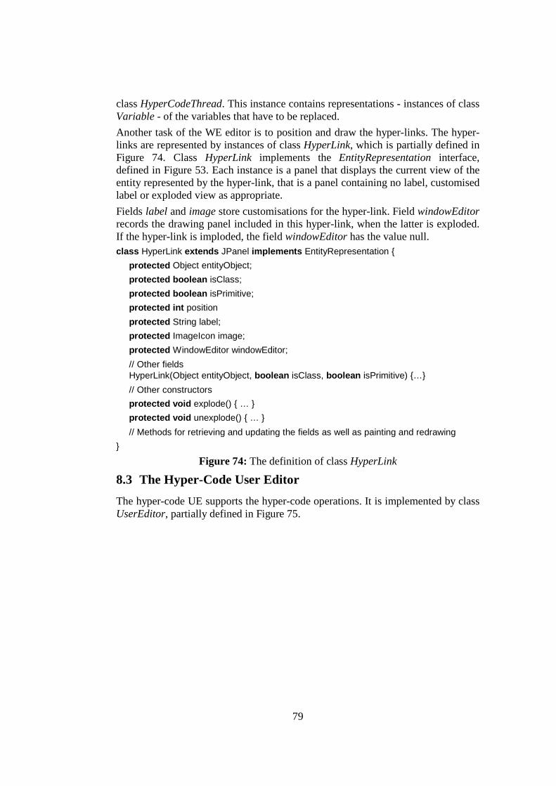
79
class HyperCodeThread. This instance contains representations - instances of class Variable - of the variables that have to be replaced. Another task of the WE editor is to position and draw the hyper-links. The hyper-links are represented by instances of class HyperLink, which is partially defined in Figure 74. Class HyperLink implements the EntityRepresentation interface, defined in Figure 53. Each instance is a panel that displays the current view of the entity represented by the hyper-link, that is a panel containing no label, customised label or exploded view as appropriate. Fields label and image store customisations for the hyper-link. Field windowEditor records the drawing panel included in this hyper-link, when the latter is exploded. If the hyper-link is imploded, the field windowEditor has the value null. class HyperLink extends JPanel implements EntityRepresentation {
protected Object entityObject; protected boolean isClass; protected boolean isPrimitive; protected int position protected String label; protected ImageIcon image; protected WindowEditor windowEditor; // Other fields HyperLink(Object entityObject, boolean isClass, boolean isPrimitive) {…} // Other constructors protected void explode() { … } protected void unexplode() { … } // Methods for retrieving and updating the fields as well as painting and redrawing
}
Figure 74: The definition of class HyperLink
8.3 The Hyper-Code User Editor The hyper-code UE supports the hyper-code operations. It is implemented by class UserEditor, partially defined in Figure 75.
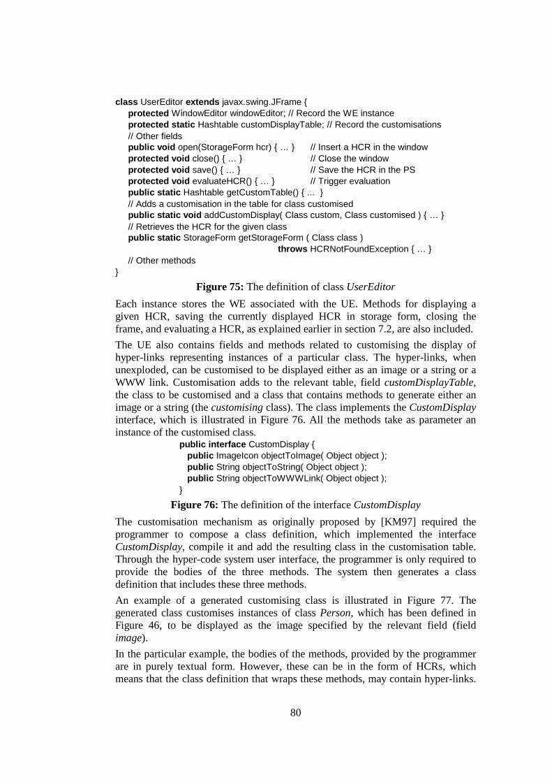
80
class UserEditor extends javax.swing.JFrame { protected WindowEditor windowEditor; // Record the WE instance protected static Hashtable customDisplayTable; // Record the customisations // Other fields public void open(StorageForm hcr) { … } // Insert a HCR in the window protected void close() { … } // Close the window protected void save() { … } // Save the HCR in the PS protected void evaluateHCR() { … } // Trigger evaluation public static Hashtable getCustomTable() { ... } // Adds a customisation in the table for class customised public static void addCustomDisplay( Class custom, Class customised ) { … } // Retrieves the HCR for the given class public static StorageForm getStorageForm ( Class class ) throws HCRNotFoundException { … } // Other methods
} Figure 75: The definition of class UserEditor
Each instance stores the WE associated with the UE. Methods for displaying a given HCR, saving the currently displayed HCR in storage form, closing the frame, and evaluating a HCR, as explained earlier in section 7.2, are also included. The UE also contains fields and methods related to customising the display of hyper-links representing instances of a particular class. The hyper-links, when unexploded, can be customised to be displayed either as an image or a string or a WWW link. Customisation adds to the relevant table, field customDisplayTable, the class to be customised and a class that contains methods to generate either an image or a string (the customising class). The class implements the CustomDisplay interface, which is illustrated in Figure 76. All the methods take as parameter an instance of the customised class.
public interface CustomDisplay { public ImageIcon objectToImage( Object object ); public String objectToString( Object object ); public String objectToWWWLink( Object object );
}
Figure 76: The definition of the interface CustomDisplay The customisation mechanism as originally proposed by [KM97] required the programmer to compose a class definition, which implemented the interface CustomDisplay, compile it and add the resulting class in the customisation table. Through the hyper-code system user interface, the programmer is only required to provide the bodies of the three methods. The system then generates a class definition that includes these three methods. An example of a generated customising class is illustrated in Figure 77. The generated class customises instances of class Person, which has been defined in Figure 46, to be displayed as the image specified by the relevant field (field image). In the particular example, the bodies of the methods, provided by the programmer are in purely textual form. However, these can be in the form of HCRs, which means that the class definition that wraps these methods, may contain hyper-links.
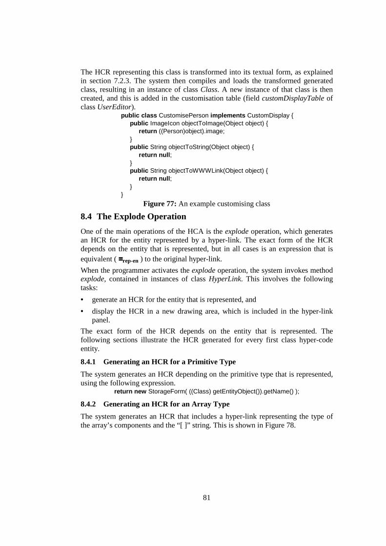
81
The HCR representing this class is transformed into its textual form, as explained in section 7.2.3. The system then compiles and loads the transformed generated class, resulting in an instance of class Class. A new instance of that class is then created, and this is added in the customisation table (field customDisplayTable of class UserEditor).
public class CustomisePerson implements CustomDisplay { public ImageIcon objectToImage(Object object) {
return ((Person)object).image; } public String objectToString(Object object) {
return null; } public String objectToWWWLink(Object object) {
return null; }
} Figure 77: An example customising class
8.4 The Explode Operation One of the main operations of the HCA is the explode operation, which generates an HCR for the entity represented by a hyper-link. The exact form of the HCR depends on the entity that is represented, but in all cases is an expression that is equivalent ( ≡≡≡≡rep-en ) to the original hyper-link. When the programmer activates the explode operation, the system invokes method explode, contained in instances of class HyperLink. This involves the following tasks: • generate an HCR for the entity that is represented, and • display the HCR in a new drawing area, which is included in the hyper-link
panel. The exact form of the HCR depends on the entity that is represented. The following sections illustrate the HCR generated for every first class hyper-code entity.
8.4.1 Generating an HCR for a Primitive Type The system generates an HCR depending on the primitive type that is represented, using the following expression.
return new StorageForm( ((Class) getEntityObject()).getName() );
8.4.2 Generating an HCR for an Array Type The system generates an HCR that includes a hyper-link representing the type of the array’s components and the “[ ]” string. This is shown in Figure 78.

82
Vector tempVector = new Vector(); Class componentType = ((Class)getEntityObject()).getComponentType(); tempVector.addElement( new StorageFormHL( componentType, true, false, 0) ); return new StorageForm(" []",tempVector);
Figure 78: Code to generate an HCR for an array type
8.4.3 Generating an HCR for a Class or Interface The system retrieves the HCR from the vector of persistent HCRs, using method getStorageForm of class UserEditor, with the class or interface represented by the hyper-link as parameter. Any class definition created through the hyper-code system has its corresponding HCR. However, some classes do not have a corresponding persistent HCR, such as the classes included in the standard JDK 2. Generating HCRs for those classes is possible, but these would be incomplete as source code cannot be generated for methods and constructors using the Java reflection package. Thus, the system simply generates an HCR containing the name of the class. This process is shown in Figure 79.
try { return UserEditor.getStorageForm( ((Class)getEntityObject()).getName() ); } catch (HCRNotFoundException e) { // HCR not found, so it returns the name of the class return new StorageForm( ((Class)getEntityObject()).getName() ); }
Figure 79: Code to generate an HCR for a class or interface
8.4.4 Generating an HCR for a Primitive Value The system generates an HCR representing the primitive value, as shown in the following expression:
return new StorageForm( getEntityObject().toString() );
8.4.5 Generating an HCR for an Array Ideally, exploding a hyper-link representing an array should return an informative expression that would be syntactically valid and sufficient to create a copy of the array. The standard JDK 2 provides the static method System.arrayCopy, which duplicates an array. However, an HCR containing such an expression would not be informative, as it would not contain hyper-links to the elements of the array. Therefore, the hyper-code system generates a HCR representing an array by performing the following tasks: • create a class definition that contains a static method. The static method takes
as parameters the elements of the original array. Inside the body of the method a new array is created and its elements are initialised by the parameters provided.
• compile and load the generated class definition. This results in an instance of class Class.
• create a HCR containing a hyper-link to the resulting class, an expression to invoke the static method, and hyper-links to the elements of the original array.
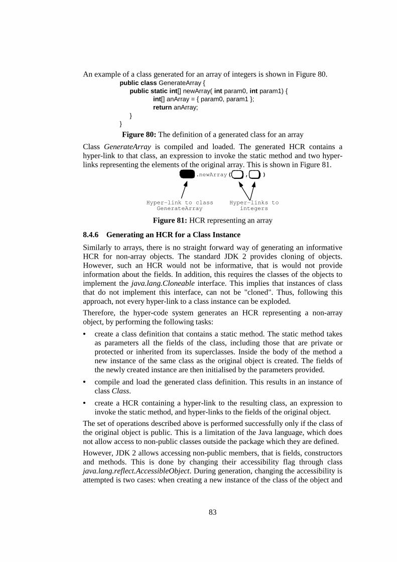
83
An example of a class generated for an array of integers is shown in Figure 80. public class GenerateArray { public static int[] newArray( int param0, int param1) { int[] anArray = { param0, param1 }; return anArray; } }
Figure 80: The definition of a generated class for an array Class GenerateArray is compiled and loaded. The generated HCR contains a hyper-link to that class, an expression to invoke the static method and two hyper-links representing the elements of the original array. This is shown in Figure 81.
.newArray( , )
Hyper-link to classGenerateArray
Hyper-links tointegers
Figure 81: HCR representing an array
8.4.6 Generating an HCR for a Class Instance Similarly to arrays, there is no straight forward way of generating an informative HCR for non-array objects. The standard JDK 2 provides cloning of objects. However, such an HCR would not be informative, that is would not provide information about the fields. In addition, this requires the classes of the objects to implement the java.lang.Cloneable interface. This implies that instances of class that do not implement this interface, can not be "cloned". Thus, following this approach, not every hyper-link to a class instance can be exploded. Therefore, the hyper-code system generates an HCR representing a non-array object, by performing the following tasks: • create a class definition that contains a static method. The static method takes
as parameters all the fields of the class, including those that are private or protected or inherited from its superclasses. Inside the body of the method a new instance of the same class as the original object is created. The fields of the newly created instance are then initialised by the parameters provided.
• compile and load the generated class definition. This results in an instance of class Class.
• create a HCR containing a hyper-link to the resulting class, an expression to invoke the static method, and hyper-links to the fields of the original object.
The set of operations described above is performed successfully only if the class of the original object is public. This is a limitation of the Java language, which does not allow access to non-public classes outside the package which they are defined. However, JDK 2 allows accessing non-public members, that is fields, constructors and methods. This is done by changing their accessibility flag through class java.lang.reflect.AccessibleObject. During generation, changing the accessibility is attempted is two cases: when creating a new instance of the class of the object and
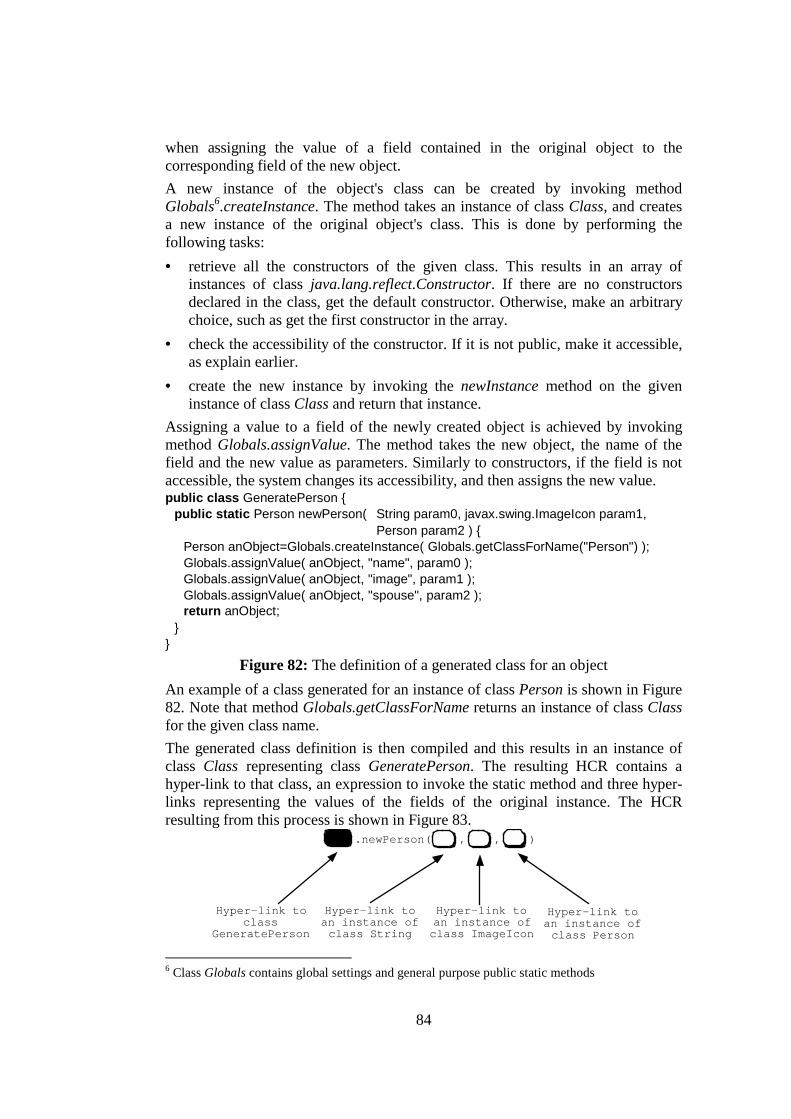
84
when assigning the value of a field contained in the original object to the corresponding field of the new object. A new instance of the object's class can be created by invoking method Globals6.createInstance. The method takes an instance of class Class, and creates a new instance of the original object's class. This is done by performing the following tasks: • retrieve all the constructors of the given class. This results in an array of
instances of class java.lang.reflect.Constructor. If there are no constructors declared in the class, get the default constructor. Otherwise, make an arbitrary choice, such as get the first constructor in the array.
• check the accessibility of the constructor. If it is not public, make it accessible, as explain earlier.
• create the new instance by invoking the newInstance method on the given instance of class Class and return that instance.
Assigning a value to a field of the newly created object is achieved by invoking method Globals.assignValue. The method takes the new object, the name of the field and the new value as parameters. Similarly to constructors, if the field is not accessible, the system changes its accessibility, and then assigns the new value. public class GeneratePerson {
public static Person newPerson( String param0, javax.swing.ImageIcon param1, Person param2 ) {
Person anObject=Globals.createInstance( Globals.getClassForName("Person") ); Globals.assignValue( anObject, "name", param0 ); Globals.assignValue( anObject, "image", param1 ); Globals.assignValue( anObject, "spouse", param2 ); return anObject;
} }
Figure 82: The definition of a generated class for an object An example of a class generated for an instance of class Person is shown in Figure 82. Note that method Globals.getClassForName returns an instance of class Class for the given class name. The generated class definition is then compiled and this results in an instance of class Class representing class GeneratePerson. The resulting HCR contains a hyper-link to that class, an expression to invoke the static method and three hyper-links representing the values of the fields of the original instance. The HCR resulting from this process is shown in Figure 83.
.newPerson( , , )
Hyper-link toclass
GeneratePerson
Hyper-link toan instance ofclass String
Hyper-link toan instance ofclass Person
Hyper-link toan instance ofclass ImageIcon
6 Class Globals contains global settings and general purpose public static methods
85
Figure 83: HCR representing a non-array object
8.4.7 Displaying the Generated HCR The last stage of the explode operation is to draw the HCR in a newly created WE. The WE is then added in the hyper-link panel, which is resized automatically. Exploding hyper-links at any level results in creating new nested WEs, which may contain more hyper-links. This combination of WEs included in hyper-links forms a tree of instances of class WindowEditor and HyperLink respectively.
8.5 Summary This chapter discusses the implementation issues related to the Hyper-Code Assistant tool and to operation explode. The HCA is the only tool visible to the programmer. It is used to composed and evaluate HCRs. It is designed to support exploding and imploding of hyper-links, basic editing facilities and multiple fonts, colours and styles. It is structured using three layers: • the Basic Editor (BE) stores and manipulates the editing form and supports
the manipulation of the HCR data structure. • the Window Editor (WE) supports the graphical display and editing of the
HCR, and this involves the manipulation of multiple fonts, styles, sizes and colours.
• the User Editors (UE) are high-level tools built on top of the WE. One of these tools is the hyper-code UE, which implements the hyper-code concepts.
The explode operation generates an HCR for the entity represented by a hyper-link. This involves generating an HCR for that entity and displaying the HCR in a new drawing area. Exploding a hyper-link at any level may result in several nested WEs and hyper-links. The source code for the classes described in chapters 7 and 8 can be found at the following URL:
http://www-ppg.dcs.st-and.ac.uk/Languages/Java/HCS

86
9 Conclusions The research described in this thesis is based on the Aristotelian distinction between the way reality is structured and the way it is viewed. In the context of the thesis, this means that the problem of building software can be approached in different ways. As an example, the task of programming may be viewed at different levels of abstraction, such as at the machine level, at the operating system level and at the higher level. Programming at each level requires manipulation of different abstractions, representations and operations. Some of these concepts are essential for programming at the particular level. The rest are considered accidents as they can be hidden either by specifying new abstract concepts or by providing different tools. The motivation for the research is to improve programmers' productivity in the task of developing software. The hypothesis of the thesis is that this can be achieved by making a system simpler. A simple system may be produced by removing unnecessary complexity, for example by presenting to a programmer either fewer or more understandable concepts and forms. In programming environments following the traditional life-cycle, the programmer is required to be aware of various operations and many different forms and tools. Simplification may be achieved both at an abstract level and at a concrete level [ZKM00].
9.1 Simplification at the Abstract Level The thesis presents a different way of structuring the reality, which simplifies the traditional programming life-cycle. A new set of abstract concepts is introduced. These shape the hyper-code abstraction, which describes the software life-cycle in terms of two domains and four abstract operations. The two domains are: the domain of language entities (hyper-code entities) and the domain of concrete representations of entities, which is the only domain made explicit to the programmer. The domain operations map between and within the two domains. These are purely definitional and they are not visible to the programmer. These operations are: reflect, reify, execute and transform. The hyper-code abstraction is designed to structure the reality in a more understandable way than the traditional life-cycle, thus easing the task of programming.
9.2 Simplification at the Concrete Level Hyper-code continues the chain of simplification steps starting from the introduction of persistence. Orthogonal persistence brought about several simplifications of the programmer’s task. One was to unify short-term and long-term data. Another was to unify data and code, in the sense that executable code became first-class and could be manipulated in the same way as other data. Hyper-programming involved a further unifying simplification step. In hyper-programming, source programs are themselves persistent data and are manipulated in the same way as other values.
87
Hyper-code builds on these simplifications by further unifying source code and executable code. The result is that the distinction between them is completely removed. The programmer sees only a single program representation form, the Hyper-Code Representation, throughout the software life-cycle, during program construction, execution, debugging, and viewing existing programs and data. As a consequence, only a single programming tool is required to manipulate this uniform representation form, rather than the various program editors, data browsers, debuggers, etc needed otherwise. This single tool is the Hyper-Code Assistant Tool. Various processes such as compilation and linking are accidental and hidden from the programmer. The hyper-code view of a programming system may be implemented through a Hyper-Code System, which provides through the single tool a suitable set of operations so that the design goals can be met. One set of operations is: explode, implode, evaluate, edit and getRoot. The consequence is that the hyper-code abstraction structures the reality in a way that results in fewer and more understandable accidents. The one-representation / one- tool model simplifies the task of programming; according to the original hypothesis this improves programmers' productivity. Quantitative testing of this hypothesis would require extensive user evaluation.
9.3 Hyper-Code Systems and Related Work Several other programming environments attempt to simplify the traditional programming life-cycle. However, most of these environments attempt to solve problems caused by accidental difficulties, rather than introducing a new way of viewing the reality. The survey of the related work indicated that most modern programming environments hide concepts of the traditional programming life-cycle in one way or another. Hiding interchange forms, or providing a better user interface for composing programs are some examples of attempts towards that goal. Nevertheless, all of these systems present the programmer with different representations for programs and data during all stages of the software development process. In addition, the operations performed require multiple tools, each one of which may consist of several windows. As an example, in some systems debugging requires a window containing breakpoints, which is usually the editor window, and a window to monitor values at run-time. Therefore, there is an indication that a hyper-code system provides a better solution to the problem of simplifying the traditional programming life-cycle than other systems. Extensive user evaluation may be required in order to test this on a quantitative basis.
9.4 Current Design and Implementation Status The thesis reports on mapping the hyper-code concepts to particular languages (ProcessBase and PJama). This includes the specific definition of the domains and the definition of the concrete operations with respect to the particular

88
interpretations of the underlying domain operations. The user interface for each of the concrete operations is also described. In addition, at the time of writing (September 2000), a prototype implementation of a HCS in PJama (PJ-HCS), demonstrating the hyper-code concepts, has been completed. The implementation of variable tracking and breakpoint manipulation is ongoing. More details about the current status of implementation can be found at
http://www-ppg.dcs.st-and.ac.uk/Research/HyperCode/.
9.5 General Discussion of HCSs The thesis reports on a particular style of HCSs, which involves the specification of a particular set of HCOs performed over HCRs. This section discusses several issues related to: • the particular HCR chosen. • the particular set of HCOs chosen. • the mapping of the hyper-code concepts into concrete HCSs in particular
languages. Two issues may be of interest: – the way that the features of particular languages affect the mapping of
those languages to hyper-code. – the essential and desirable features of a language for which hyper-code is
being implemented.
9.5.1 Choosing the Particular HCR The HCR is defined to have the hyper-programming form. Although the particular HCR form chosen fulfils the criteria introduced earlier in section 4.1, it does not deal adequately with displaying cyclic data structures, which means that the HCR does not explicitly show cyclic data structures. For this problem, a possible solution would be to alter the default behaviour of the explode operation. When exploding a hyper-link that represents an entity that is part of a cycle, explode would draw an arrow starting from the hyper-link to be exploded and pointing to an already exploded hyper-link representing that entity. This is shown in Figure 84 where Hyper-Link 3 represents the same entity as Hyper-Link 1. When exploding Hyper-Link 3, an arrow indicates that the requested detailed representation is already included in Hyper-Link 1. The arrow also denotes the cyclic data structure.
Hyper-Code Assistant
Hyper-Link 1
Hyper-Link 2
Hyper-Link 3
Figure 84: Denoting cyclic data structures
89
9.5.2 Choosing the Particular Set of HCOs The set of concrete HCOs described, that is explode, implode, evaluate, edit and get root, is just one example of the many possible sets that could support the required programming activities. It does appear to be simple and minimal, at least in comparison with some of the earlier operation sets from which it evolved during this work. For example, in one version there was a distinction between inspection of an entity, which generated a read-only representation, and modification, in which a representation could be edited and then reflected into a new entity that would replace the original. This scheme turned out to be unnecessarily complex and was too closely coupled with issues of mutability in a particular language. In a later version separate operations for expanding a hyper-link in place and for expanding it to give a new hyper-code fragment were defined. This was unnecessary given the ability to copy the hyper-code within an exploded link, so the two operations were replaced by the single explode. It is not clear whether this operation set is suitable for all languages (without the get root operation for non-persistent languages); it appears to be suitable for PJama and for ProcessBase.
9.5.3 Mapping Hyper-Code Into Particular Languages Several general conclusions can be drawn from the experience of designing and implementing particular HCSs in ProcessBase and PJama, as described in chapters 4, 5, 6 and 7. These conclusions are related to the following: • The entities that can be hyper-linked. • The way that a language affects the form of the representation of entities. • The way that a particular language protects data and how this affects the
HCOs. • Whether the language supports mutable locations and how this affects HCOs. • Whether the system supports third-party executable code without source code. • Whether the language provides persistence and referential integrity. • Whether a HCS preserves compatibility with a language and its components.
9.5.3.1 Hyper-Linking One of the decisions in designing a HCS for a particular language is related to which language entities can be represented by a single hyper-link. The simplest choice is to allow hyper-linking of all the language constructs. However, not all constructs can be hyper-linked in practice. For example, in a HCS for PJama, constructs that are not hyper-linked are locations, methods and constructors. In a HCS for ProcessBase, constructs that are not hyper-linked are interrupt and op-code types. In Java, fields, array elements and local variables are all locations. Location expressions are dereferenced implicitly and can be considered either as L or R values depending on the context. Allowing hyper-linking to L values is
90
problematic since there is no self-contained representation for them. Therefore, for the particular implementation, hyper-linking is not supported for L values. Java methods and constructors are not first class values, as they are not assignable and cannot be passed as parameters. They are not self-contained, as they can only be defined within a class. Consequently, no full self-contained HCR can be generated when a hyper-link is exploded. Therefore, for the particular implementation, hyper-linking of methods and constructors is not supported. ProcessBase interrupt and op-code types cannot be hyper-linked since there is no valid syntax in the language for them. Based on these observations related to which language constructs cannot be hyper-linked, the following guidelines are used to specify the constructs that can be hyper-linked: • The language constructs must be self-contained, which means that they must
be consistent when defined in isolation. • There is a valid syntax in the language for them.
9.5.3.2 Generating Detailed HCRs for Entities Explode is defined to present the programmer with a detailed representation of the hyper-linked entity. When exploding a hyper-link to an entity, this representation is sufficient to create a new entity, if evaluated separately. The exploded HCR captures the entity’s current state and not the way it was created. This may be a problem as the HCR, when evaluated separately, may cause undesirable side-effects or may not cause desirable side-effects. There is no way for the system to predict which case is suitable as this depends on the context of the particular application. In Java, for example, the HCR resulting from explode contains an invocation of an object constructor, which creates a new instance, if evaluated separately, possibly causing side-effects. Depending on the application, these side-effects may or may not be desirable. Thus, no conclusion can be drawn related to whether the resulting HCR is suitable or not, as this is application dependant. However, a desirable language feature for the explode operation is to provide single expression constructs for creating new entities. For example, ProcessBase provides such convenient constructs to create new views and vectors, that is the closest analogues to objects. The generated HCR resulting from exploding in this case contains a single view or a vector expression, which initialises all the fields, as explained earlier in section 5.3.1. In PJama, objects are created using one of the constructors included in a class. In order to generate a representation for an object, the system simulates the ProcessBase approach; a class containing a method, which invokes a constructor and initialises all the fields, is generated. The system makes an arbitrary choice for selecting a constructor, and that is selecting the default constructor. The desirable representation is an expression that invokes the generated method. This approach is necessary since there is no single expression to achieve these tasks.

91
9.5.3.3 Information Hiding The explode operation relies on the system’s ability to introspect over entities and is required since explode should be able to discover the internal structure of the entity, in order to generate an HCR. However, exploding entities that hide information is problematic, as the system does not have access to this information in order to generate HCRs. Consequently, the programmer is presented with less information than an HCR that fulfils the requirements described in section 4.1. Different languages provide different approaches to the way that data is hidden from general access. Nevertheless, in some cases this data can be revealed. Consequently a HCS can produce a full HCR. This precludes real information hiding, as the programmer is presented with information that is meant to be hidden. Java, for example, supports information hiding by encapsulation. This is specified by the protected and private modifiers, which restrict access to them outside the package or class they are used respectively. Data is encapsulated in a class or an object and may only be accessed through the corresponding methods, which means that private or protected members cannot be accessed directly. Therefore when the system attempts to generate an HCR for an entity, only public members can be accessed, resulting in a representation that is not complete. Class java.lang.reflect.AccessibleObject provides a solution to accessing hidden fields. This class allows changing the accessibility permissions of private or protected fields and consequently allows this information to be presented to the programmer. In this case, a HCS uses this class when exploding a hyper-link representing an object. A restriction that cannot be bypassed is that explode cannot be performed over hyper-links that represent instances of a non-public class. In this case, the HCS in PJama attempts to refer to this class in the body of the corresponding generated method that creates a new object and initialises all the fields. This attempt fails as the class is not public, which means that it cannot be accessed outside the package it is defined. In ProcessBase the only information hiding mechanism is the procedure closure, in which the access path to data used by the procedure may be hidden from general access. The way to bypass this is to hyper-link this data and reveal it when the procedure closure is exploded. In order to achieve that, the system changes textual representations of identifiers into hyper-links during evaluation and records them on closure formation.
9.5.3.4 Mutable Locations The issue here is that in some languages, such as Java, an identifier may denote either a location or the current value of that location, depending on its context. As explained earlier in section 9.5.3.1, L values are not hyper-linked in that case. This affects operation evaluate, where a special class of identifier link is required, which behaves differently from all others in that the linked value changes during evaluation on each update.

92
Another problem in the HCS in PJama is that during evaluation, the programmer may copy a link to the location of a variable on the stack, which represents its current value, and paste it in another window. The semantics of this after exiting the scope of the variable are not clear. The pragmatic, but unsatisfactory solution for the HCS in PJama is that copying the link gives only the corresponding textual identifier. Both of these problems are avoided if mutable locations are first class, as in ProcessBase, which provides an explicit location constructor. This simplifies matters — in the first example, the value bound to a link now never changes, although if the value is a location its contents may. In the second example, the location automatically persists beyond the method invocation, and so the link continues to denote the same location wherever it is pasted.
9.5.3.5 Openness The hyper-code scheme relies on source code being either recorded or generated as required for all entities, so that the explode operation can show details. This is feasible in a self-contained persistent system, in which all entities are originally derived from the evaluation of source code. However, it does not work in an open system that has to deal with third-party code for which source is not available. As an example, this is true for much of the standard Java class libraries, as well as for most commercial Java software. An example of the problems that this may cause is when exploding a hyper-link to a standard Java class. Since there is no source code to generate an HCR, the system provides merely the name of the class as the HCR. Such a representation complies with all the requirements related to HCRs, but it is not as informative as desired. Another solution would be to generate approximations to the source code, using reflection facilities. For example, when exploding a hyper-link to a class, the resulting HCR would contain the fields and only the declaration of constructors and methods without including source for their bodies. This approach results in a more informative HCR than the previous solution but still does not accurately denote the represented entity.
9.5.3.6 Persistence and Referential Integrity The issue here is that in a persistent HCS, HCRs can be stored together with other values in the persistent store, without requiring an explicit save operation from the programmer. This means that when exploding a hyper-link representing a procedure closure or a class, there is always a corresponding HCR, which can be retrieved from the persistent store and presented to the programmer. At the implementation level, persistence with referential integrity is a desirable feature for a system when transforming hyper-links into textual representations. In this, a textual specification of the path of the hyper-linked entity replaces the original hyper-link. This transformation is required if the compiler only accepts purely textual specifications.
93
Such a transformation is required for the particular implementation of a HCS, as explained in section 7.2.3. In this, the path that replaces the original hyper-link denotes an entity which is referenced through a vector of references to objects.
9.5.3.7 Compatibility An implementation decision for the particular HCSs described in the thesis is to build the system on top of existing tools. The particular implementation of a HCS in PJama uses the Java language, the standard JVM and the standard reflection mechanisms. The motivation for this is compatibility with future releases of Java running on any platform. This decision affects several hyper-code operations, such as explode and evaluate. An example is the use of reflection facilities provided by standard Java libraries. Package java.lang.Reflect provides good support for introspection over class structure. It does not, however, provide introspection over method code, even at the byte level, or dynamic access to the compiler. The current implementation provides dynamic compilation, but it would be simpler if it was supported directly. Another issue is that current Java compilers, including the one provided by the current implementation, work only at the granularity of complete textual class definitions. This requires the system to transform a HCR from its hyper-programming form into textual form. In addition there is a considerable overhead involved in processing small expressions since they must also been wrapped up into complete classes.
9.5.4 Essential and Desirable Features for Hyper-Code The following mechanisms are essential for hyper-code: • Structural reflection over types: a HCS must be able to introspect over
entities in order to produce an HCR when required. For the particular set of operations introduced in this thesis, this is required by explode and get root.
• Dynamic compilation facilities: a HCS must be able to dynamically compile representations in order to produce their corresponding entities. For the particular set of operations introduced in this thesis, this is required by evaluate.
• Graphical user interface: a HCS must be able to provide the environment through which programmers compose HCRs. For the particular set of operations introduced in this thesis, this is required by edit.
Sections 9.5.3.1 — 9.5.3.7 described several desirable language features for hyper-code, without which the mapping onto languages is unsatisfactory. The thesis demonstrates that it is possible to implement hyper-code in a language that does not provide all these features, such as PJama. However, it is believed that it would be cleaner and simpler to implement hyper-code in languages that do provide most of these features, such as ProcessBase. The desirable language features are beneficial when designing a HCS. Some affect the simplicity and elegance of the resulting system, while others impact on the ease of implementation. Summarising the above, these features are:

94
• all the values being first class, and types with syntax in the language. • single expressions to create new entities. • direct access to programs and data without any restrictions—no information
hiding. • first class locations. • control over source of executable code. • persistence and referential integrity. • structural reflection over code and compiler accepting HCRs.
9.6 Further Research Work Further research work may include: • Investigation of alternative hyper-code operations: the set of operations
described here was designed to fulfil certain criteria, but it is likely that other completely different operations could also fulfil them.
• Investigation of alternative hyper-code representation: the HCR described here was designed to fulfil certain criteria, but it is likely that other completely different HCRs could also fulfil them.
• Provision of HCR transformation at the user level to/from other formats, such as HTML and XML.
• Investigation of byte code transformation as opposed to pre-compile time transformation: the hyper-code system inserts additional fragments of code just before compilation in order to perform variable tracking and breakpoint manipulation. An alternative technique would be to perform byte code transformation at class loading time [MZB+00], [Chi00]. This would probably give considerably better performance for the evaluate operation, at the cost of greater complexity.
• Mapping hyper-code to the ProcessBase language: the design of a HCS in ProcessBase indicated that mapping hyper-code to ProcessBase is possible. It is intended to provided such an implementation as part of current research into compliant architectures [MB00], [MBG+00].
9.7 Final Thoughts A HCS provides a good, convenient and non ad-hoc solution to the problem of developing software, but it is not a panacea for every problem. It is just a better view of the reality.
95
My fellow Athenian, I wish I knew about hyper-code when I talked about reality.

96
10 Appendix
10.1 Index of Tables Table 1: Essential concepts and accidents at each level of programming................3 Table 2: Comparison of features provided in various systems...............................24 Table 3: Comparing various programming environments......................................25 Table 4: Appearance of representations of ProcessBase entities............................42 Table 5: Definition equivalence over ProcessBase entities in E ............................42 Table 6: Exploding hyper-links to ProcessBase values and identifiers ..................44 Table 7: Exploding hyper-links to ProcessBase types............................................45 Table 8: Evaluating ProcessBase HCRs.................................................................48 Table 9: Appearance of representations of PJama entities .....................................52 Table 10: Definition of the ≡≡≡≡en equivalence over PJama entities in E....................52 Table 11: Exploding hyper-links to variables and objects......................................53 Table 12: Exploding hyper-links to types...............................................................54 Table 13: Evaluating PJama HCRs.........................................................................56 Table 14: Use of StorageFormHL fields for each category of entity .....................64

97
10.2 Index of Figures Figure 1: Programming at different levels of abstraction.........................................2 Figure 2: The traditional programming life cycle.....................................................6 Figure 3: Traditional access to long-lived data.........................................................7 Figure 4: Systems that attack accidents of the traditional software life-cycle .........8 Figure 5: A snapshot of editing Java programs in Emacs ........................................9 Figure 6: A snapshot of an example project ...........................................................10 Figure 7: A snapshot of editing and browsing in CodeWarrior Java .....................10 Figure 8: Composing an application in Visual Basic .............................................11 Figure 9: A snapshot of a Smalltalk browser window displaying a class ..............13 Figure 10: Evaluating expressions in Dolphin Smalltalk .......................................14 Figure 11: Browsing tools in the Trellis programming environment .....................15 Figure 12: An IPSE architecture.............................................................................16 Figure 13: Accessing data in an orthogonal persistent system...............................19 Figure 14: First class executable code ....................................................................20 Figure 15: Hyper-programming in Napier88..........................................................22 Figure 16: Hyper-Programming in PJama..............................................................22 Figure 17: Accessing source and executable code in HP systems..........................23 Figure 18: The unification chain towards a hyper-code system.............................24 Figure 19: Sets in the entities domain.....................................................................26 Figure 20: Sets in the representation domain .........................................................27 Figure 21: Domains and domain operations...........................................................27 Figure 22: Categorisation of HCSs.........................................................................29 Figure 23: Accessing data in a hyper-code system.................................................33 Figure 24: An example HCA window containing an HCR ....................................35 Figure 25: The HCR of Figure 24 after imploding its hyper-links.........................36 Figure 26: Snapshots of the evaluation process......................................................37 Figure 27: The persistent roots HCA window........................................................38 Figure 28: Searching in a HCS ...............................................................................40 Figure 29: A ProcessBase HCR that produces an error..........................................46 Figure 30: Snapshots of evaluating a ProcessBase HCR........................................46 Figure 31: An example of an identifier that escapes its scope ...............................47 Figure 32: An HCR representing a closure.............................................................47 Figure 33: The persistent roots HCA window........................................................48 Figure 34: Composing a ProcessBase HCR ...........................................................48 Figure 35: Updating a ProcessBase location ..........................................................49 Figure 36: Customising a particular hyper-link......................................................49 Figure 37: Customising hyper-links representing values of the specified type......50 Figure 38: The definition of class Person and its superclass..................................53 Figure 39: A PJama HCR that produces an error ...................................................55 Figure 40: Snapshots of evaluating a PJama HCR .................................................56 Figure 41: The persistent roots and classes HCA windows ...................................57
98
Figure 42: Composing a PJama HCR.....................................................................57 Figure 43: Customising a particular hyper-link......................................................58 Figure 44: Customising hyper-links to instances of the specified class .................58 Figure 45: An example HCR in PJama...................................................................59 Figure 46: The definition of class Person...............................................................59 Figure 47: Transforming between the three HCR forms ........................................60 Figure 48: The evaluation algorithm ......................................................................61 Figure 49: Transforming storage form into textual form........................................61 Figure 50: An instance of the storage form ............................................................62 Figure 51: The definition of class StorageForm.....................................................62 Figure 52: The definition of class StorageFormHL ...............................................63 Figure 53: The definition of interface EntityRepresentation ..................................63 Figure 54: Transforming the example HCR into a class definition........................64 Figure 55: Transforming a non-void HCR .............................................................65 Figure 56: Transforming an HCR representing a primitive value..........................65 Figure 57: Accessing a hyper-linked entity in the persistent store .........................65 Figure 58: Transforming the example HCR into its textual form ..........................67 Figure 59: The definition of class HyperCodeThread ............................................69 Figure 60: The definition of class Variable ............................................................69 Figure 61: The result of transforming the example HCR.......................................71 Figure 62: An example class definition ..................................................................71 Figure 63: Transforming the example class definition of Figure 62 ......................72 Figure 64: The definition of class DynamicCompiler ............................................72 Figure 65: Initialising and starting a thread............................................................73 Figure 66: Code in the body of the run method......................................................73 Figure 67: Starting a thread for executing the evaluateVoid method .....................74 Figure 68: Invoking method evaluateVoid inside method run ...............................74 Figure 69: The layers implementing the HCA .......................................................76 Figure 70: The editing form data structure .............................................................77 Figure 71: The definition of class BasicEditor.......................................................77 Figure 72: The definition of class WindowEditor...................................................78 Figure 73: The definition of class StyleRun............................................................78 Figure 74: The definition of class HyperLink .........................................................79 Figure 75: The definition of class UserEditor ........................................................80 Figure 76: The definition of the interface CustomDisplay .....................................80 Figure 77: An example customising class ..............................................................81 Figure 78: Code to generate an HCR for an array type ..........................................82 Figure 79: Code to generate an HCR for a class or interface .................................82 Figure 80: The definition of a generated class for an array....................................83 Figure 81: HCR representing an array....................................................................83 Figure 82: The definition of a generated class for an object ..................................84 Figure 83: HCR representing a non-array object....................................................85 Figure 84: Denoting cyclic data structures .............................................................88
99
11 References [ABC+83] Atkinson, M.P., Bailey, P.J., Chisholm, K.J., Cockshott, W.P. &
Morrison, R. “An Approach to Persistent Programming”. Computer Journal 26, 4 (1983) pp 360-365.
[ADJ+96] Atkinson, M.P., Daynès, L., Jordan, M.J., Printezis, T. & Spence, S. “An Orthogonally Persistent Java™”. ACM SIGMOD Record 25, 4 (1996) pp 68-75.
[AJ96] Atkinson, M.P. & Jordan, M.J. (eds) Persistence and Java. Sun Microsystems SMLI-TR-96-58 (1996).
[AJD+96] Atkinson, M.P., Jordan, M.J., Daynès, L. & Spence, S. “Design Issues for Persistent Java: a Type-Safe, Object-Oriented, Orthogonally Persistent System”. In Proc. 7th International Workshop on Persistent Object Systems, Cape May, NJ, USA, Connor, R.C.H. & Nettles, S. (eds) (1996) pp 33-47.
[AM85] Atkinson, M.P. & Morrison, R. “Procedures as Persistent Data Objects”. ACM Transactions on Programming Languages and Systems 7, 4 (1985) pp 539-559.
[AM95] Atkinson, M.P. & Morrison, R. “Orthogonally Persistent Object Systems”. VLDB Journal 4, 3 (1995) pp 319-401.
[And99] Andersen, V. “dBase IV 2.0 Programmer's Reference”, ISBN 1583483969 (1999).
[App86] Apple Computer Inc. “Inside Macintosh”. Addison-Wesley, Reading, Massachusetts (1986).
[Bac86] Bach, M.J. “The Design of the UNIX Operating System”. Prentice-Hall, Englewood Cliffs, New Jersey (1986).
[BOP+89] Bretl, B., Maier, D., Otis, A., Penney, J., Schuchardt, B., Stein, J., Williams, E.H. & Williams, M. “The GemStone Data Management System”. In Object-Oriented Concepts, Databases and Applications, Kim, W. & Lochovsky, F. (eds), ACM Press and Addison Wesley (1989) pp 283-308.
[Bor89] Borland International “Turbo Pascal”. Borland International, Scotts Valley, California (1989).
[Bot89] Bott, M.F. (ed) ECLIPSE: An Integrated Project Support Environment. Peter Peregrinus (1989).
[Bro86] Brooks, F.P. “No Silver Bullet – Essence and Accidents of Software Engineering”. In Proc. Information Processing 86 (1986) p 1069.
[CB98] Connolly, T.M. & Begg, C.E. “Database Systems” (2nd Edition). Addison-Wesley, Harlow, UK, ISBN 0-201-34287-1 (1998).

100
[CCK+94c] Connor, R.C.H., Cutts, Q.I., Kirby, G.N.C., Moore, V.S. & Morrison, R. “Unifying Interaction with Persistent Data and Program”. In Interfaces to Database Systems, Sawyer, P. (ed), Springer-Verlag, Proc. 2nd International Workshop on User Interfaces to Databases, Ambleside, Cumbria, 1994, In Series: Workshops in Computing, van Rijsbergen, C.J. (series ed) (1994) pp 197-212.
[Chi00] Chiba, S. “Load-Time Structural Reflection in Java”. To Appear: ECOOP 2000 (2000).
[Coo90] Cooper, R.L. “On The Utilisation of Persistent Programming Environments”. PhD Thesis, University of Glasgow (1990).
[Dat93] Date, C.J. & Darmen, H. “A guide to the SQL” (3rd Edition). Addison- Wesley (1993).
[Dav92] Davie, A. “A Introduction to Functional Programming Systems using Haskell”. Cambridge University Press, ISBN 0 521 27724 8 (1992).
[DB88] Dearle, A. & Brown, A.L. “Safe Browsing in a Strongly Typed Persistent Environment”. Computer Journal 31, 6 (1988) pp 540-544.
[Dow98] Dowling, N. “Database Design & Management”. Ashford Colour Press (1998).
[GJS96] Gosling, J., Joy, B. & Steele, G. “The Java™ Language Specification”. Addison-Wesley, ISBN 0-201-63451-1 (1996).
[Gli97] Glickstein, B. “Writing GNU Emacs Extensions” (First Edition). O'Reilly & Associates Inc, ISBN 1-56592-261-1 (1997).
[GR83] Goldberg, A. & Robson, D. “Smalltalk-80: The Language and its Implementation”. Addison Wesley, Reading, Massachusetts (1983).
[HM76] Henderson, P. & Morris, J. “A Lazy Evaluator”. In Proc. 3rd ACM Symposium on principles of Programming Languages (1976).
[Int99] Intuitive Systems “Dolphin Smalltalk”. (1999) [KCC+92] Kirby, G.N.C., Connor, R.C.H., Cutts, Q.I., Dearle, A., Farkas, A.M.
& Morrison, R. “Persistent Hyper-Programs”. In Persistent Object Systems, Albano, A. & Morrison, R. (eds), Springer-Verlag, Proc. 5th International Workshop on Persistent Object Systems (POS5), San Miniato, Italy, In Series: Workshops in Computing, van Rijsbergen, C.J. (series ed), ISBN 3-540-19800-8 (1992) pp 86-106.
[KCC+93] Kirby, G.N.C., Cutts, Q.I., Connor, R.C.H. & Morrison, R. “The Implementation of a Hyper-Programming System”. University of St Andrews Technical Report CS/93/5 (1993).
[Kir92] Kirby, G.N.C. “Reflection and Hyper-Programming in Persistent Programming Systems”. PhD Thesis, University of St Andrews. Technical Report CS/93/3 (1992).
[KM97] Kirby, G.N.C. & Morrison, R. “OCB Object Class Browser”. University of St Andrews (1997).

101
URL: http://www-ppg.dcs.st-and.ac.uk/Languages/Java/OCB/ [KMS98] Kirby, G.N.C., Morrison, R. & Stemple, D.W. “Linguistic Reflection
in Java”. Software - Practice & Experience 28, 10 (1998) pp 1045-1077.
[KR78] Kernighan, B.W. & Ritchie, D.M. “The C Programming Language”. Prentice-Hall, New Jersey (1978).
[Lu91] Luce, T. “Computer Hardware, System Software, and Architecture”. Mitchell Publishing Inc (1991).
[MB00] Morrison, R., Balasubramaniam, D., Greenwood, R.M., Kirby, G.N.C., Mayes, K., Munro, D.S. & Warboys, B.C. “A Compliant Persistent Architecture”. Software - Practice and Experience, Special Issue on Persistent Object Systems 30, 4 (2000) pp 363-386.
[MBC+96b] Morrison, R., Brown, A.L., Connor, R.C.H., Cutts, Q.I., Dearle, A., Kirby, G.N.C. & Munro, D.S. “Napier88 Release 2.2.1”. University of St Andrews (1996).
[MBG+00] Morrison, R., Balasubramaniam, D., Greenwood, R.M., Kirby, G.N.C., Mayes, K., Munro, D.S. & Warboys, B. “An Approach to Compliance in Software Architectures”. To Appear: IEE Informatics 1, Sommerville, I. (ed) (2000).
[MBG+99b] Morrison, R., Balasubramaniam, D., Greenwood, M., Kirby, G.N.C., Mayes, K., Munro, D.S. & Warboys, B.C. “ProcessBase Reference Manual (Version 1.0.6)”. Universities of St Andrews and Manchester (1999).
[MBG+99d] Morrison, R., Balasubramaniam, D., Greenwood, M., Kirby, G.N.C., Mayes, K., Munro, D.S. & Warboys, B.C. “ProcessBase Standard Library Reference Manual (Version 1.0.4)”. Universities of St Andrews and Manchester (1999).
[MCC+95] Morrison, R., Connor, R.C.H., Cutts, Q.I., Dunstan, V.S. & Kirby, G.N.C. “Exploiting Persistent Linkage in Software Engineering Environments”. Computer Journal 38, 1 (1995) pp 1-16.
[MCD+99] Morrison, R., Connor, R.C.H., Cutts, Q.I., Dearle, A., Farkas, A., Kirby, G.N.C., McGettrick, R. & Zirintsis, E. “Current Directions in Hyper-Programming”. In Lecture Notes in Computer Science 1755, Bjorner, D., Broy, M. & Zamulin, A. (eds), Springer-Verlag, Proc. 3rd International Andrei Ershov Memorial Conference on Perspectives of System Informatics (PSI), Novosibirsk, Russia, ISBN 3-549-67102-1 (1999) pp 316-340.
[MCK+96] Morrison, R., Connor, R.C.H., Kirby, G.N.C. & Munro, D.S. “Can Java Persist?”. In Proc. 1st International Workshop on Persistence for Java (PJW1), Drymen, Scotland (1996), Technical Report Sun Microsystems Laboratories SMLI TR-96-58.
102
[MCK+99] Morrison, R., Connor, R.C.H., Kirby, G.N.C., Munro, D.S., Atkinson, M.P., Cutts, Q.I., Brown, A.L. & Dearle, A. “The Napier88 Persistent Programming Language and Environment”. In Fully Integrated Data Environments, Atkinson, M.P. & Welland, R. (eds), Springer, In Series: Esprit Basic Research Series, ISBN 3-540-65772-X (1999) pp 98-154.
[Met99] Metrowerks Inc “CodeWarrior”. (1999) URL: http://www.metrowerks.com/
[Mic94] Microsoft Corporation “Microsoft Access: User's Guide”. (1994). [Mic96] Microsoft “Microsoft Visual Basic”. (1996) URL:
http://www.microsoft.com [Mic97] Microsoft, C. “Microsoft Visual Basic Online”. (1997). [Mic98] Microsoft Corporation “Microsoft® Visual Basic® 6.0
Programmer's Guide”. Microsoft Press, ISBN 1-57231-863-5 (1998).
[Mic98+] Microsoft “Microsoft® Windows 98”. (1998) URL: http://www.microsoft.com
[Mor79] Morrison, R. “On the Development of Algol”. PhD Thesis, University of St Andrews (1979).
[MS87] Morrison, R. & Sommerville, I. “Software Development with Ada”. Addison-Wesley Publishers Ltd, ISBN 0-201-14227-9 (1987).
[MZB+00] Marquez, A., Zigman, J.N. & Blackburn, S.M. “Fast Portable Orthogonally Persistent Java”. Software - Practice and Experience, Special Issue on Persistent Object Systems 30, 4 (2000) pp 449-479.
[NA99] Naughton, P. & Schildt, H. “Java 2 - The Complete Reference” (3rd Edition). Brandon A. Nordin (1999).
[Nai93] Naiman, A., Dunn, E., MacAllister, S. & Kadyk, J. “The Macintosh Bible”. Peachpit Press (1993).
[OHK87] O’Brien, P.D., Halbert, D.C. & Kilian, M.F. “The Trellis Programming Environment”. ACM SIGPLAN Notices 22, 12. Proc. International Conference on Object-Oriented Programming Systems, Languages and Applications (OOPSLA'87), Orlando, Florida (1987) pp 91-102.
[Ros28] Ross, W.D. “The Works of Aristotle Translated in English”. Oxford University Press (1928).
[Set96] Sethi, R. “Programming Languages”. Addison-Wesley Publishing Company (1996).
[Sno89] Snowdon, R.A. “An Introduction to the IPSE 2.5 Project”. ICL Technical Journal 6, 3 (1989) pp 467-478.
[ST86] Sommerville, I. & Thomson, R. “The ECLIPSE System Structure Language”. In Proc. 19th International Conference on System Sciences, Hawaii (1986).
103
[Sta97] Stallman, R. “GNU Emacs Manual” (13 Edition). Free Software Foundation (1997).
[SWP89] Sommerville, I., Welland, R., Potter, S. & Smart, J. “The ECLIPSE User Interface”. Software—Practice and Experience 19, 4 (1989) p 371.
[Tan87] Tanenbaum, A.S. “Operating Systems: Design and Implementation”. Prentice Hall (1987).
[Tsi77] Tsichritzis, D. & Lochovsky, F. “Data Base Management Systems”. Academic Press Inc (1977).
[TT99] Thompson, T. & Trudeau, J. “CodeWarrior's Architectural Advantage”. Metrowerks, Inc (1999).
[Ull80] Ullman, J. “Principles of database Systems”. Computer Science Press Inc (1980).
[War89] Warboys, B. “The IPSE 2.5 Project: Process Modelling as the Basis for a Support Environment”. In Proc. 1st International Conference on System Development Environments and Factories, Berlin, Germany (1989).
[War95] Warhol, M. “The art of programming with VISUAL BASIC” (Tim Ryan Edition). John Wiley (1995).
[Wir71] Wirth, N. “The Programming Language Pascal”. Acta Informatica 1 (1971) pp 35-63.
[You84] Young, S.J. “An Introduction to ADA” (2 Edition). Ellis Horwood (1984).
[ZDK+99] Zirintsis, E., Dunstan, V.S., Kirby, G.N.C. & Morrison, R. “Hyper-Programming in Java”. In Advances in Persistent Object Systems, Morrison, R., Jordan, M. & Atkinson, M.P. (eds), Morgan Kaufmann, Proc. 8th International Workshop on Persistent Object Systems (POS8) and 3rd International Workshop on Persistence and Java (PJW3), Tiburon, California, 1998, ISBN 1-55860-585-1 (1999) pp 370-382.
[ZKM00] Zirintsis, E., Kirby, G.N.C. & Morrison, R. “Hyper-Code Revisited: Unifying Program Source, Executable and Data”. (In Preparation 2000).
[ZKM98] Zirintsis, E., Kirby, G.N.C. & Morrison, R. “Java Hyper-Program System”. University of St Andrews (1998). URL: http://www-ppg.dcs.st-and.ac.uk/Languages/Java/HPS/
[ZKM99] Zirintsis, E., Kirby, G.N.C. & Morrison, R. “Demonstration of Hyper-Programming in Java”. In Proc. 25th International Conference on Very Large Databases (VLDB'99), Edinburgh, Scotland, Atkinson, M.P., Orlowska, M.E., Valduriez, P., Zdonik, S. & Brodie, M. (eds) (1999) pp 734-737. o