the hypot - clonica: seo/sem, analisis, programación ... · ac hipot, dc hipot, insulation...
TRANSCRIPT


Associated Research, Inc started as a repair company servicing panel meters and instruments back in 1936. Founder James Inman soon made Associated Research a manufacturer when he designed the Vibrotest. Vibrotest, the first battery operated Insulation Resistance Tester ever created, became standard issue on all U.S. Navy ships during World War II. This was the beginning of what would become many industry breakthroughs for Associated Research. As the number of electrical products increased during the post-war economic boom, Mr. Inman realized the need for rugged quality test instruments. AR was again on the leading edge this time with the introduction of the Hypot® high potential tester for electrical safety testing. Hipot testing soon became our forte. True to the beliefs that our founder, James F. Inman, instituted back in 1936, we continue to offer the highest quality instruments on the market.
AR has continued to innovate and develop advanced products in the electrical safety compliance testing industry from basic entry-level Hipot and Ground Bond testers to automated multi-function electrical safety compliance analyzers. Our instruments are designed to test to the requirements set forth by safety agencies such as UL, TUV, CSA, IEC, VDE, BSI and European norms. We offer a variety of testers capable of performing AC Hipot, DC Hipot, Insulation Resistance, Ground Bond, Ground Continuity, Line Leakage and Functional Run Testing. We also provide Medical Safety Test systems, modular scanning matrices, and our Autoware testing software to meet the testing needs and requirements of our customers. We have developed the most complete line of automation interfaces for our products, including Ethernet, GPIB, RS-232 and USB. All of our testers also incorporate easy-to-use menus.
Our experience and leadership have helped to shape the industry and our dedication to product development continues to improve the safety testing process for manufacturers around the globe. We are committed to providing the highest quality, most advanced instrumentation on the market. Our instruments all carry the CE Mark and all of our standard testers carry a Nationally Recognized Testing Laboratory (NRTL) listing mark. This demonstrates our commitment to provide you with the safest and most innovative testers on the market – a commitment our competitors simply cannot make. Furthermore, Associated Research, Inc. is an ISO 9001 registered company which demonstrates our commitment to quality!

As the industry leader we also guarantee our customers' satisfaction. If for any reason you are not completely satisfied with your purchase within 45 days, you can receive a full refund, exchange or credit towards another AR product, no questions asked. Our instruments are backed by the industry’s best warranty. We offer a standard one year warranty on all of our instruments with the opportunity to extend that warranty for a full five years if the instrument is returned to our factory service center each year for its annual certification and safety inspection. We also offer a three year warranty for those who are unable to take advantage of the factory certification that is part of our extended warranty program.
AR is dedicated to making sure that your testing solution provides you with complete satisfaction for years to come. This is why we offer the most comprehensive
service program in the industry. Our service program ensures that you receive the value you deserve when using an AR tester.
We offer expedient calibration and repair work performed by expert technicians who work exclusively with AR instruments. We have a host of calibration options to match the broad needs of all of our customers. We offer calibration services from our standard calibration to our accredited calibration including ISO 17025 calibration, ANSI Z540.1 calibration, CTL and Denan’s Law calibration. We have industry leading turn-around time and guarantee 24-hour turn-around for standard calibrations. A guaranteed 48-hour turn-around time is provided on all of our flat rate repair work. If we don’t ship your instrument in time, we’ll pay the shipping cost. In addition, all of our calibration and service work is backed by a 90
day service warranty.
We understand that finding the right electrical safety testing solution can be a difficult task. That is why we offer our customers a comprehensive selection of educational resources from regional seminars and online webinars to on-site factory sponsored training programs. We also offer an extensive library of technical booklets, articles and white papers. At AR, we want to ensure that your investment is maximized and that your tester performs safely and reliably.
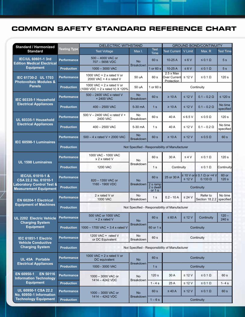
COMMON SAFETY STANDARD REFERENCE CHART
Standard / HarmonizedStandard
Testing TypeDIELECTRIC WITHSTAND GROUND BOND/CONTINUITY
Test Voltage Max I.Test Time
Test Current V Limit Max. R Test Time
IEC/UL 60601-1 3rd Edition Medical Electrical
Equipment
Performance500 – 4000 VAC or 707 – 5656 VDC No
Breakdown
60 s 10-25 A ≤ 6 V ≤ 0.1 Ω 5 s
Production 1000 – 3000 VAC 1 or 60 s 10-25 A ≤ 6 V ≤ 0.1 Ω 5 s
IEC 61730-2 UL 1703 Photovoltaic Modules &
Panels
Performance1000 VAC + 2 x rated V or
2000 VAC + 4 x rated V50 uA 60 s
2.5 x Max Over Current
Protection≤ 12 V ≤ 0.1 Ω 120 s
Production1000 VAC + 2 x rated V or
(1000 VDC + 2 x rated V) X 120%50 uA 1 or 60 s Continuity
IEC 60335-1 Household Electrical Appliances
Performance500 – 2400 VAC x rated V
+ 2400 VACNo
Breakdown60 s ≥ 10 A ≤ 12 V 0.1 – 0.2 Ω ≤ 120 s
Production 400 – 2500 VAC 5-30 mA 1 s ≥ 10 A ≤ 12 V 0.1 – 0.2 ΩNo time specified
UL 60335-1 Household Electrical Appliances
Performance500 V – 2400 VAC x rated V +
2400 VACNo
Breakdown60 s 40 A ≤ 6.5 V ≤ 0.5 Ω 120 s
Production 400 – 2500 VAC 5-30 mA 1 s 40 A ≤ 12 V 0.1 – 0.2 ΩNo time specified
IEC 60598-1 Luminaires
Performance 500 – 4 x rated V + 2000 VACNo
Breakdown60 s ≥ 10 A ≤ 12 V ≤ 0.5 Ω 60 s
Production Not Specified - Responsibility of Manufacturer
UL 1598 Luminaires
Performance1000 VAC - 1000 VAC
x 2 x rated V No Breakdown
60 s 30 A ≤ 4 V ≤ 0.1 Ω 120 s
Production 1200 VAC 1 s Continuity ≤ 0.1 Ω Continuity
IEC/UL 61010-1 & CSA 22.2 No. 61010-1
Laboratory Control Test & Measurement Equipment
Performance820 – 1350 VAC or 1160 - 1900 VDC
No Breakdown
60 s 25 or 30 A≤ 10 V or
≤ 12 V≤ 0.1 Ω or <4 V
0.133 Ω60 or 120 s
Production2 s ramp 2 s dwell
or 1 sContinuity
EN 60204-1 Electrical Equipment of Machines
Performance2 x rated V or
1000 VACNo
Breakdown1 s 0.2 - 10 A ≤ 24 V
Refer to Section 18.2.2
No time specified
Production Not Specified - Responsibility of Manufacturer
UL 2202 Electric Vehicle Charging System
Equipment
Performance500 VAC or 1000 VAC
+ 2 x rated V No Breakdown
60 s ≤ 60 A ≤ 12 V Continuity120 – 240 s
Production 1000 – 1700 VAC + 3.4 x rated V 60 or 1 s Continuity
IEC 61851-1 Electric Vehicle Conductive Charging System
Performance1200 VAC + rated V
or DC EquivalentNo
Breakdown60 s Continuity
Production Not Specified - Responsibility of Manufacturer
UL 45A Portable Electrical Appliances
Performance1000 VAC + 2 x rated V or
DC equivalent No Breakdown
60 s Continuity
Production 1000 - 3000 VAC 1 s Continuity
EN 60950-1 EN 50116 Information Technology
Equipment
Performance 1000 – 3000 VAC or 1414 – 4242 VDC
No Breakdown
120 s 30 A ≤ 12 V ≤ 0.1 Ω 60 s
Production 1 - 4 s 25 A ≤ 12 V ≤ 0.1 Ω 1- 4 s
UL 60950-1 CSA 22.2 No. 60950-1 Information Technology Equipment
Performance 1000 – 3000 VAC or 1414 – 4242 VDC
No Breakdown
60 s ≤ 40 A ≤ 12 V ≤ 0.1 Ω 60 s
Production 1 – 6 s Continuity
EARTH LEAKAGE INSULATION RESISTANCE SUGGESTED MODEL #Testing Type
Standard / HarmonizedStandardTest Voltage Max I. Test Time V Limit Min R ARI Instrument
110% x rated V
5-10 mA N/A 8106 or MedTEST Performance IEC/UL 60601-1 3rd Edition Medical Electrical
EquipmentN/A N/A 8104 or 8204 Production
Max rated V 10 uA – 1 mA 60s500 VDC or Max rated V
40-400 MΩ 8106 or MedTEST Performance IEC 61730-2 UL 1703 Photovoltaic Modules &
PanelsN/A N/A 3770 or 7650 Production
1.06 x rated V 0.25 – 5.0 uA N/A 7704 & 620L PerformanceIEC 60335-1 Household Electrical Appliances
N/A N/A 7704 Production
1.06 x rated V 0.25 – 5.0 uA N/A 7704 & 620L PerformanceUL 60335-1 Household Electrical Appliances
N/A N/A 7704 Production
Rated V 0.5 – 10 mA 60 s 500 VDC 1-4 MΩ 8106 Performance
IEC 60598-1 LuminairesNot Specified - Responsibility of Manufacturer Hypot III or 7650 Production
N/ANo time specified
500 VDC ≥ 2 MΩ 8104 or 8204 Performance
UL 1598 Luminaires N/A N/A Hypot III or 7650 Production
< 300 V 0.5 mA N/A 8106 or MedTEST Performance IEC/UL 61010-1 & CSA 22.2 No. 61010-1 Laboratory
Control Test & Measurement EquipmentN/A N/A 3765 or 7650 Production
N/ANo time specified
500 V ≥ 1 MΩ 8104 or 8204 PerformanceEN 60204-1 Electrical
Equipment of MachinesNot Specified - Responsibility of Manufacturer Hypot III or 7650 Production
Rated V0.5 - 0.75 mA
or 5 mAN/A 8106 or MedTEST Performance
UL 2202 Electric Vehicle Charging System Equipment
N/A N/A Hypot III or 7650 Production
Touch Current Only 60 s 500 V≥ 1 MΩ or ≥
7 MΩ 8106 or MedTEST Performance IEC 61851-1 Electric Vehicle
Conductive Charging SystemNot Specified - Responsibility of Manufacturer Hypot III or 7650 Production
< 300 V 0.5 – 3.5 mA 60 s 500 V ≥ 50 KΩ 8106 or MedTEST Performance UL 45A Portable Electrical Appliances
N/A N/A Hypot III or 7650 Production
< 300 V 0.25 – 3.5 mA 60 s 500 V ≥ 2 MΩ 8106 or MedTEST Performance EN 60950-1 EN 50116 Information Technology
EquipmentN/A N/A 8104 or 8204 Production
< 300 V 0.25 – 3.5 mA 60 s 500 V ≥ 2 MΩ 8106 or MedTEST Performance UL 60950-1 CSA 22.2 No. 60950-1 Information Technology EquipmentN/A N/A Hypot III or 7650 Production

AC Hipot DC Hipot Insulation Resistance Ground Bond Functional Run Line Leakage
AC Hipot DC Hipot Insulation Resistance Ground Bond Functional Run Line Leakage
AC Hipot DC Hipot Insulation Resistance Ground Bond Functional Run Line Leakage
AC Hipot DC Hipot Insulation Resistance Ground Bond Functional Run Line Leakage
AC Hipot DC Hipot Insulation Resistance Ground Bond Functional Run Line Leakage
AC Hipot DC Hipot Insulation Resistance Ground Bond Functional Run Line Leakage
MedTEST is our comprehensive Medical Electrical Safety Tester. MedTEST can be custom designed to meet all of your medical safety testing needs. It complies with test requirements called out in common medical electrical safety specifications such as UL2601, UL60601, IEC601-1, IEC60601-1 and EN60601-1.
OMNIA® II 8204
OMNIA®
8104
8105
8106
HypotMAX®
7700
7704
7705
7710
7715
7720
HypotULTRA® III 7620
7650
Hypot® III 3705
3765
3770
3780
HYAMP® III 3130
3140
3160
LINECHEK® II 620L

USB/RS-232 GPIBEthernet/
Data Storage/RS-485
Interconnection to External
Scanner Autoware DualCHEKInternalScanner
Color TFTDisplay
USB/RS-232 GPIBEthernet/
Data Storage/RS-485
Interconnection to External
Scanner Autoware DualCHEKInternalScanner
Color TFTDisplay
USB/RS-232 GPIBEthernet/
Data Storage/RS-485
Interconnection to External
Scanner Autoware DualCHEKInternalScanner
Color TFTDisplay
USB/RS-232 GPIBEthernet/
Data Storage/RS-485
Interconnection to External
Scanner Autoware DualCHEKInternalScanner
Color TFTDisplay
USB/RS-232 GPIBEthernet/
Data Storage/RS-485
Interconnection to External
Scanner Autoware DualCHEKInternalScanner
Color TFTDisplay
USB/RS-232 GPIBEthernet/
Data Storage/RS-485
Interconnection to External
Scanner Autoware DualCHEKInternalScanner
Color TFTDisplay
Visit our Product Selection Wizard, designed to help find the right testers for your application. Through a series of questions we will be able to suggest the perfect tester for you. Go to www.asresearch.com and follow the link to the Product Selection Wizard.
OMNIA® II 8204
OMNIA®
8104
8105
8106
HypotMAX®
7700
7704
7705
7710
7715
7720
HypotULTRA® III 7620
7650
Hypot® III 3705
3765
3770
3780
HYAMP®
3130
3140
3160
LINECHEK® II 620L
RS-232 Opt.
RS-232 Only
RS-232 Only
RS-232 Only
RS-232 Only

An Electrical Safety Compliance Analyzer That Is As Unique As Your Application!OMNIA II, our next generation of Electrical Safety Compliance Analyzers, is designed around the way you test. We understand that every testing application is unique and finding the right tester can be difficult. OMNIA II model 8204 is a multi-function Electrical Safety Compliance Analyzer that provides you with customizable features and unmatched functionality.
Model 8204 - 4-in-1 Electrical Safety Compliance Analyzer that performs AC Hipot, DC Hipot, 40 Amp Ground Bond and Insulation Resistance testing in a single instrument.
Safety agency listed.
Color TFT Display – the 8204 provides an 800 x 480 Color TFT display that makes setting up test files, viewing results, and performing tests easier than ever. Color-coded test steps clearly indicate pass/fail conditions. Choose from 3 different color schemes to match your preferences.
“My Menu” Interface – the 8204 is equipped with our “My Menu” interface which allows operators to personalize menu settings. Create shortcuts to your favorite screens and preferences for unmatched ease and speed in setup.
DualCHEK – the DualCHEK feature allows the user to perform a simultaneous Hipot and Ground Bond test. This can safely increase productivity and throughput on the production line.
Multiple Automation Interfaces – the 8204 comes standard with a USB/RS-232 interface. The 8204 is also available with optional Ethernet, GPIB, Data Storage, and printer output interfaces.
Multiple Language Settings – the 8204 is available in two language settings. Users can select to view the menu in English or Traditional Chinese.
Patented SmartGFI® function - The SmartGFI is a high speed shutdown circuit that provides maximum operator protection. If the circuit detects excessive leakage to ground it shuts down the high voltage output in less than 1 millisecond. SmartGFI is automatically activated if the DUT is not grounded with no need for operator input.
Expanded Test Memories – The 8204 allows users to link a total of 10,000 test steps. This allows users to create and save even the most complex test setups.
Patented Prompt and Hold function – The prompt and hold function allows users to insert prompts or instructions as part of the test cycle. This helps to eliminate operator error when changing test leads is required as part of the test cycle.
Patented CAL-ALERT® function - The patented CAL-ALERT feature automatically alerts the user when the instrument is due for calibration. This eliminates the need for manual tracking of calibration dates.
Patented VERI-CHEK® function - The VERI-CHEK feature is a menu-driven process by which the instrument’s failure detectors are proven to be functioning properly, “verify-ing” the functionality of the electrical safety tester and connected accessories.
CHARGE LO® - The Charge-LO Circuit sets a minimum charging current which is based on the DC test voltage, the rate of rise, and the capacitance of the DUT. This circuit confirms that the DUT is connected when perform-ing a test.
RAMP HI® - The Ramp-HI feature prevents the test from failing during ramp up due to excessive charging current. This allows you to charge the DUT as rapidly as possible without causing false failures.
Features and Benefits
APT AC Power Source Compatible
www.aspowertechnologies.com

Input SpecificationsVoltage 115/230 VAC ± 15% Auto Range
Frequency 50/60 Hz ± 5%
Fuse 115 VAC, 230 VAC - 5A/250 VAC Slow Blow
Dielectric Withstand Test ModeOutput Rating 5 kV @ 50 mAAC 5 kV @ 20 mADC
Voltage Setting Range: 0 - 5000 VAC 0 - 5000 VDC Resolution: 1 V Accuracy: ± (2% of Setting + 5 V)
HI and LO-Limit AC Total Range: 0.000-9.999 mA Resolution: 0.001 mA Accuracy: ± (2% of setting + 2 counts) Range: 10.00 - 50.00 mA Resolution: 0.01 mA Accuracy: ± (2% of Setting + 2 Counts) AC Real Range: 0.000-9.999 mA Resolution: 0.001 mA Accuracy: ± (3% of Setting + 50 µA) Range: 10.00 - 50.00 mA Resolution: 0.01 mA Accuracy: ± (3% of Setting + 50 µA) DC Range: 0.00 - 999.9 µA Resolution: 0.1 µA Accuracy: ± (2% of Setting + 2 Counts) Range: 1000 - 20000 µA Resolution: 1 µA Accuracy: ± (2% of Setting + 2 Counts)
Ramp HI >20 mA peak maximum, ON/OFF User Selection
Charge LO Range: 0.0 - 350.0 µA DC or Auto Set
DC Output Ripple < 4 % (5 kV/20 mA at Resistive Load)
Discharge Time < 50 msec for no load, < 100 msec for capcitor load (all capacitance values in MAX load spec below)
Max Capacitive Load 1 µF < 1 kV 0.08 µF < 4 kV DC Mode 0.75 µF < 2 kV 0.04 µF < 5 kV 0.5 µF < 3 kV
AC Output Waveform Sine Wave. Crest Factor = 1.3 - 1.5
Output Frequency 50/60 Hz ± 0.1% , User Selection, 400/800 Hz Option
Output Regulation ± (1% of output + 5 V), From no load to full load and Low Line to High Line (combined regulation)
Dwell Timer AC 0, 0.4 - 999.9 (0=continuous) DC 0, 0.3 - 999.9 (0=continuous)
Ramp Timer Ramp-Up AC: 0.1 - 999.9 Ramp-Down AC: 0.0-999.9 Ramp-Up DC: 0.4 - 999.9 Ramp-Down DC: 0.0, 1.0-999.9
Ground Continuity Current: DC 0.1 A ± 0.01A, fixed Max. Ground Resistance: M
Ground Fault Interrupt GFI Trip Current: 5.0 mA max HV Shut Down Speed: < 1 ms
Arc Detection 1 - 9 Ranges (9 is the most sensitive)
For more information on testing to a specfic standard, refer back to the Common Safety Standard Reference Chart.
Continuity Test ModeOutput Current DC 0.1 A ± 0.00001 A
Resistance Display Range: 1.00 - 10000 Ω
HI and LO-Limit 0.0 - 10000 Ω
Dwell Timer Range: 0.0, 0.3 - 999.9 sec (0=continuous)
Milliohm Offset Range: 0.00 – 10.00 Ω
Insulation Resistance Test ModeOutput Voltage Range: 30 - 1000 VDC
Charging Current Maximum >20 mA peak
HI and LO-Limit Range: 0.05-99.99 MΩ Resolution: 0.01 MΩ Range: 100.0 - 999.9 MΩ Resolution: 0.1 MΩ Range: 1000 - 50000 MΩ Resolution: 1 MΩ
Charge-LO 0.000 - 3.500 µA or Auto Set
Ramp Timer Ramp-Up: 0.1 - 999.9 secs Ramp-Down: 0.0, 1.0 -999.9 secs
Dwell Timer 0, 0.5 - 999.9 (0=Continuous)
Delay Timer 0.5 - 999.9 secs
Ground Fault Interrupt GFI Trip Current: 5.0 mA max HV Shut down Speed: < 1 ms
Ground Bond Test ModeOutput Voltage Range: 3.00 - 8.00 VAC
Output Frequency 50/60 Hz ± 0.1% , User Selection
Output Current Range: 1.00 - 40.00 A Resolution: 0.01 A Accuracy: ± (2 % of setting + 2 counts)
Output Regulation ± (1% of output + 0.02A), Within maximum load limits, and over input voltage range.
Maximum Loading 1.00 - 10.00 A, 0 - 600 mΩ 10.01 - 30.00 A, 0 - 200 mΩ 30.01 - 40.00 A, 0 - 150 mΩ
HI and LO-Limit Range: 0 - 150 for 30.01 - 40.00 A Range: 0 - 200 for 10.01 - 30.00 A Range: 0 - 600 for 6.00 - 10.00 A Range: 0 - 600 for 5.99 - 1.00 A Resolution: 1 mΩ Accuracy: 6.00 - 40.00 A, ± (2% of setting + 2 Counts) Accuracy: 1.00 - 5.99 A, ± (3% of setting + 3 Counts)
Milliohm Offset Range: 0 - 200 mΩ
General SpecificationsMechanical Bench or rack mount with tilt up front feet
Dimensions 3U (WxHxD) 16.93 x 5.24 x 19.69 in. (430 x 133 x 500 mm)
Interface USB/RS-232 Standard, GPIB, Ethernet, Data Storage (RS-485), Printer Port Optional
Memory Up-to 10,000 Steps can be linked
Multilingual Choose from English (Default) and Chinese
Display Color TFT LCD. 800 x 480 Resolution. Choose from 4 different color settings
Accredited calibration service available. Includes ISO 17025, ANSI Z540.1-1994, CTL & Denan’s Law requirements.

Fully-Automated, Multi-Function Electrical Safety Compliance AnalyzerMulti-function safety compliance analyzers with an enhanced graphic LCD provide complete test setup and results with an easy-to-use interface. OMNIA® provides 4-in-1, 5-in-1 and 6-in-1 testing solutions. Testers include AC Hipot, DC Hipot, Ground Bond/Continuity, Insulation Resistance, Functional Run and Line Leakage tests. An optional internal scanner is available for the 8104, 4-in-1 tester. An additional external modular scanner is available for use with all testers. All testers come standard with USB and RS-232 interfaces. Ethernet, GPIB, and RS-485 interfaces are also available.
Model 8104 - OMNIA 4, 5 kV @ 40 mA AC, 5 kV @ 20 mA DC, IR Test, 40 Amp Ground Bond & Optional HV & HC Scanner
Model 8105 - OMNIA 5, 5 kV @ 40 mA AC, 5 kV @ 20 mA DC, IR Test, 40 Amp Ground Bond & Functional Run Test
Model 8106 - OMNIA 6, 5 kV @ 40 mA AC, 5 kV @ 20 mA DC, IR Test, 40 Amp Ground Bond, Functional Run Test & Line Leakage Test
Safety agency listed.
Patented SmartGFI® safety circuit protects the operator from shock hazards
Real Current measurement allows operators to monitor total and real current on a single screen
Patented Prompt and Hold function provides a unique method for performing multiple steps during a test cycle
Line Leakage tester with 7 different measuring devices and RMS or PEAKleakage measurements
Can be easily connected to AR’s SC6540, 620L or an APT Brand AC Power Source to provide a customizable test system
USB/RS-232, GPIB, Ethernet, or RS-485 automation interfaces available
Autoware Testing Software available for complete Automation Control
Cold Resistance Feature for Line to Neutral Continuity Testing
Patented CAL-ALERT® andVERI-CHEK® features helpto ensure that yourinstrument is calibratedand stays within specs
Data storage card available for storing and transferring test data without a connection to a PC
50 Memories with 30 stepsper memory that can bestored and recalled in anyalphanumeric combination
RAMP HI® and CHARGE LO® testing for more effective DC Hipot testing
Perform Hipot/Line Leakagewithout changing test leads
Patented Graphic LCD andintuitive menu system tosimplify the entire testingprocess from set-up to results
Features and Benefits
APT AC Power Source Compatible
www.aspowertechnologies.com

Input SpecificationsVoltage 115/230 V selectable, ± 10% variation
Frequency 50/60 Hz ± 5%
Fuse 10 A Slow Blow 250 VAC
Dielectric Withstand Test ModeOutput Rating 5 kV @ 40 mAAC 5 kV @ 20 mADC
Voltage Setting Range: 0-5000 VAC 0-5000 VDC Resolution: 1 V Accuracy: ± (2% of setting + 5 V)
Voltage Display Range: 0.00 - 5.00 kV Full Scale Resolution: 0.01 kV Accuracy: ± (2% of reading + 10 V)
HI and LO-Limit AC Total Range: 0.000-9.999 mA Resolution: 0.001 mA Range: 10.00 – 40.00 mA Resolution: 0.01 mA Accuracy: ± (2% of setting + 2 counts) AC Real Range: 0.000-9.999 mA Resolution: 0.001 mA Range: 10.00 – 40.00 mA Resolution: 0.01 mA Accuracy: ± (3% of setting + 50 µA) DC Range: 0.0-999.9 µA Resolution: 0.1 µA Range: 1000 – 20000 µA Accuracy: ± (2% of setting + 2 counts)
Current Display AC Total Range: 0.000 mA – 3.500 mA Resolution: 0.001 mA Range: 3.00 mA – 40.00 mA Resolution: 0.01 mA Accuracy: ± (2% of reading + 2 counts) AC Real Range: 0.000 mA – 9.999 mA Resolution: 0.001 mA Range: 10.00 mA – 40.00 mA Resolution: 0.01 mA Accuracy: ± (3% of reading + 50 µA) DC Range: 0.0 µA – 350.0 µA Resolution: 0.1 µA Range: 0.300 mA – 3.500 mA Resolution: 0.001 mA Range: 3.00 mA – 20.00 mA Resolution: 0.01 mA Accuracy: ± (2% of reading + 2 counts)
Ramp HI >20 mA peak maximum, ON/OFF selectable
Charge LO Range: 0.000 - 350 µA or Auto Set
DC Output Ripple ≤ 4% Ripple rms at 5 kV DC @ 20 mA, Resistive Load
Discharge Time ≤ 200 ms
Dielectric Withstand Test Mode (continued)Max Capacitive Load 1 µF < 1 kV 0.08 µF < 4 kV DC Mode 0.75 µF < 2 kV 0.04 µF < 5 kV 0.5 µF < 3 kVAC Output Waveform Sine Wave, Crest Factor = 1.3 - 1.5
Output Frequency 60 or 50 Hz, User Selecatable
Output Regulation ± (1% of output + 5 V) from no load to full load and over input voltage range
Dwell Timer AC 0.4 - 999.9 sec (0 = Continuous) DC 0.3 - 999.9 sec (0 = Continuous)
Ramp Timer Ramp-Up: AC 0.1 - 999.9 sec, DC 0.4 - 999.9 sec Ramp-Down: AC 0.0 - 999.9 sec, DC 0.0,1.0 - 999.9 sec
Ground Continuity Current: DC 0.1 A ± 0.01 A, fixed Max. Ground Resistance: 1 Ω ± 0.1 Ω, fixed
Ground Fault Interrupt GFI Trip Current: 450 µA max (AC or DC) HV Shut Down Speed: < 1 ms
Continuity Test ModeOutput Current DC 0.1 A ± 0.00001 A
Resistance Display Range: 0.00 – 10000.00 Ω
HI and LO-Limit 0.00 – 10000 Ω
Dwell Timer Range: 0.0, 0.3 - 999.9 sec (0 = Continuous)
Milliohm Offset Range: 0.00 – 10.00 Ω
Ground Bond Test ModeOutput Voltage Range: 3.00 - 8.00 VAC
Output Frequency 50/60 Hz, user selectable
Output Current Range: 1.00 - 40.00 A, Resolution: 0.01 A
Output Regulation Accuracy: ± (1% of output + 0.02 A) Within maximum load limits, and over input voltage range
Maximum Loading 1.00 - 10.00 A, 0 - 600 mΩ 10.01 - 30.00 A, 0 - 200 mΩ 30.01 - 40.00 A, 0 - 150 mΩ Current display Range: 0.00 – 40.00 A Resolution: 0.01 A Accuracy: ± (3% of setting + 0.03 A)
Ohmmeter Display Range: 0 – 150 mΩ for 30.01 – 40.00 Amps 0 – 200 mΩ for 10.01 – 30.00 Amps 0 – 600 mΩ for 6.00 – 10.00 Amps Resolution: 1 mΩ Accuracy: ± (2% of reading + 2 mΩ) Range: 0 – 600 mΩ for 1.00 – 5.99 Amps Resolution: 1 mΩ Accuracy: ± (3% of reading + 3 mΩ)

Ground Bond Test Mode (continued)HI and LO Limit Range: 0 – 150 mΩ for 30.01 – 40.00 Amps 0 – 200 mΩ for 10.01 – 30.00 Amps 0 – 600 mΩ for 1.00 – 10.00 Amps Resolution: 1 mΩ Accuracy: Same as Ohmmeter Display
Milliohm Offset Range: 0 - 200 mΩ
Insulation Resistance Test ModeVoltage Setting Range: 50 - 1000 VDC
Charging Current Maximum >20 mA peak
Resistance Display Range: 0.05 MΩ – 50000 MΩ (4 Digit, Auto Ranging) Resolution: 50 – 499 VDC 500 – 1000 VDC MΩ MΩ MΩ 0.001 0.050 – 1.999 0.050 – 9.999 0.01 2.00 – 19.99 10.00 – 99.99 0.1 20.0 – 199.9 100.0 – 999.9 1 200 – 50000 1000 – 50000
Accuracy 50 – 499 V 0.05 M – 999.9 M ± (7% of reading +2 counts) 500 – 1000 V 0.05 M – 999.9 M ± (2% of reading +2 counts) 1000 M – 9999 M ± (5% of reading +2 counts) 10000 M – 50000 M ± (15% of reading +2 counts)
HI and LO Limit Range: 0.05 M – 99.99 MΩ Resolution: 0.01 M Range: 100.0 M – 999.9 M Resolution: 0.1 M Range: 1000 M – 50000 M Resolution: 1 M (HI – Limit: 0 = OFF) Accuracy: Same as Resistance Display Accuracy
Charge LO Range: 0.000 - 3.500 µA or Auto Set
Ramp Timer Ramp-Up: 0.1 - 999.9 sec Ramp-Down: 0.0, 1.0 - 999.9 sec
Delay Timer 1.0 - 999.9 sec (0 = Continuous)
Ground Fault Interrupt GFI Trip Current: 450 µA max (AC or DC) HV Shut Down Speed: < 1 ms
General SpecificationsMechanical Bench or rack mount with tilt up front feet
Dimensions 3U (WxHxD) 16.93 x 5.24 x 19.69 in. (430 x 133 x 500 mm)
Weight 8104 - 26 kgs / 57.32 lbs. 8105/8106 - 29 kgs. / 63.93 lbs.
Interface USB/RS-232 Standard, GPIB, Ethernet, Data Storage (RS-485)
Memory 50 memories, 30 step/memory
OMNIA 8105 and 8106 Functional Run Test Mode DUT Power Voltage: 0 – 277 VAC Single Phase Unbalanced (One Hot or Line conductor and One Neutral) Current: 15 AAC max continuous Short Circuit Protection: 23 AAC, Response Time < 3s Delay Time Setting Range: 0.2 – 999.9 seconds Dwell Time Setting Range: 0.1 – 999.9 seconds (0 = Continuous)
Trip Point Voltage: Volt-Hi Settings Volt-LO Range: 0.0 – 277.0 VAC Current: Amp-HI Amp-LO Range: 0.0 – 15.00 AAC Watts: Power-HI Power-LO Range: 0 – 4200 W Power Factor: PF-HI PF-LO Range: 0.000 – 1.000 Leakage Current: Leak-HI Leak-LO Range: 0.00 – 10.00 mA (0 = OFF)
OMNIA 8106 Line Leakage Test Mode DUT Power Voltage: 0 – 277 VAC Current: 15 AAC max continuous Short Circuit Protection: 23 AAC, Response Time <3s Leakage Current Current Display rms or PEAK Range 1: 0.0 µA – 999.9 µA Resolution: 0.1 µA/step Range 2: 1000 µA – 6000 µA Resolution: 1 µA/step Accuracy rms: DC to 100 kHz ± (1.5% of reading +3 counts) >100k to 1 MHz ± 5% of reading, (10.0 µA – 6000 µA) Measuring Device A UL544 Non Patient B UL544 Patient C UL2601-1, UL60601-1, IEC601-1, IEC60601-1 EN60601-1 D UL1563 E UL1950, UL3101, UL61010, IEC950, IEC1010, IEC 60950, IEC61010, IEC60335-1, IEC60990 Fig4-U2 H IEC60990 Fig5-U3 I IEC60990 Fig3-U1
Accredited calibration service available. Includes ISO 17025, ANSI Z540.1-1994, CTL & Denan’s Law requirements.
For more information on testing to a specfic standard, refer back to the Common Safety Standard Reference Chart.

High Voltage or High Current Electrical Safety Compliance AnalyzersHypotMAX® is designed for automated applications requiring testers with either higher voltage or higher output current capability. The HypotMAX® family includes two high current testers: the 7700 3-in-1 version with 500 VA AC output and the 7704 4-in-1 version with 500 VA AC output. The high voltage testers are the 7705 10 kV AC Hipot, 7710 12 kV DC Hipot, 7715 20 kV AC Hipot and the 7720 20 kV DC Hipot. All testers come standard with USB and RS-232 interfaces. GPIB (IEEE-488) and other automation interfaces optional.
Model 7700 - 5 kV @ 100 mA AC (500 VA), 6 kV @ 10 mA DC & IR Test
Model 7704 - 5 kV @ 100 mA AC (500 VA), 6 kV @ 10 mA DC, IR, 30Amp GB
Model 7705 - 10 kV @ 20 mA AC
Model 7710 - 12 kV @ 10 mA DC
Model 7715 - 20 kV @ 10 mA AC
Model 7720 - 20 kV @ 5 mA DC
Patented SmartGFI® safetycircuit protects the operatorfrom shock hazards
50 memories that can bestored and recalled. Multi-function testers include 8steps per memory
RAMP HI® and CHARGE LO® systems for more effective DC Hipot testing
500 VA testers availablefor Higher Current Hipottest applications
Meets 200 mA short circuit requirements
Up to 20 kV AC or DC Hipottesting for manufacturerswith higher voltage testingrequirements
USB/RS-232 or GPIB automation interfaces available
4 wire measurement andmilliohm offset for accurateGround Bond test results(Model 7704)
Autoware Testing Software available for complete Automation Control
Features and Benefits

Input SpecificationsVoltage 7700/7704 100/115/200/230 VAC ± 10%, single phase, user selection 7705/7710 7715/7720 115/230 VAC ± 10%, single phase, user selection
Frequency 50/60 Hz ± 5%
Fuse 7700/7704 15 Amp 250 V fast blow internal
7705/7710 6.3 Amp, 250 V Slow Blow 7715/7720
Dielectric Withstand Test ModeOutput 7700/7704 5 kV @ 100 mAAC, 6 kV @ 10 mADCRating 7705 10 kV @ 20 mAAC 7710 12 kV @ 10 mADC 7715 20 kV @ 10 mAAC 7720 20 kV @ 5 mADC
Output 7700/7704 Range: 0 - 5 kV AC, 0 - 6 kVDCAdjustment Resolution: 1 V/step Accuracy: ± (2% of setting + 5 V) 7705 Range: 0 - 10 kVAC Resolution: 10 V/step Accuracy: ± (2% of setting + 10 V) 7710 Range: 0 - 12 kVDC Resolution: 10 V/step Accuracy: ± (2% of setting + 10 V) 7715 Range: 0 - 20 kVAC Resolution: 10 V/step Accuracy: ± (2% of setting + 10 V) 7720 Range: 0 - 20 kVDC Resolution: 10 V/step Accuracy: ± (2% of setting + 10 V)
HI-Limit 7700/7704 AC Range: 0.00 - 99.00 mAand LO-Limit Hi-Limit Resolution: 0.01 mA/step DC Range: 0 - 9999 µA Resolution: 1 µA/step Accuracy: ± (2% of setting + 2 counts) LO-Limit AC Range: 0.000 - 9.999 mA Resolution: 0.001 mA/step DC Range: 0 - 999.9 µA Resolution: 1 µA/step Accuracy: ± (2% of setting + 2 counts) 7705 Range 1: 0.0 - 9.999 mA Resolution: 0.001 mA/step Range 2: 10.00 - 20.00 mA Resolution: 0.01 mA Accuracy: ± (2% of setting + 2 counts) 7710 Range 1: 0.000 - 999.9 µA Resolution: 0.1 µA/step Range 2: 1000 - 9999 µA Resolution: 1 µA Accuracy: ± (2% of setting + 2 counts) 7715 Range: 0.00 - 9.999 mA Resolution: 0.001 mA/step Accuracy: ± (2% of setting + 2 counts) 7720 Range 1: 0.0 – 999.9 µA Resolution: 0.1 µA/step Range 2: 1000 – 5000 µA Resolution: 1 µA/step Accuracy: ± (2% of setting + 2 counts)
Dielectric Withstand Test Mode (continued)DC Ramp HI 7700/7704 12 mA peak maximum, (ON/OFF selectable all testers) 7710 13 mA peak maximum, 10 mADC, ON/OFF selectable 7720 6.75 mA peak maximum, 5 mADC, ON/OFF selectable
DC Charge LO 7700/7704 Range: 0.0 - 350 µADC or auto set 7710/7720
Arc Detection 7700, 7704, 7710, 7720: 1-9 7705: 1 - 9 at output voltage < 7.00 kV 1 - 8 at output voltage ≥ 7.00 kV 7715: 1 - 9 at output voltage < 15.00 kV 1 - 7 at output voltage ≥ 15.00 kV
Voltage 7700/7704 Range: 0.00 - 6.00 kV full scaleDisplay Resolution: 10 V/step Accuracy: ± (2% of reading + 2 counts) 7705 Range: 0.00 - 10.00 kV Full scale Resolution: 10 V Accuracy: ± (2% of reading + 20 V) 7710 Range: 0.00 - 12.00 kV Full scale Resolution: 10 V Accuracy: ± (2% of reading + 2 counts) 7715 Range: 0.00 - 20.00 kV Full scale Resolution: 10 V Accuracy: ± (2% of reading + 20 V) 7720 Range: 0.00 - 20.00 kV Full scale Resolution: 10 V Accuracy: ± (2% of reading + 20 V)Current 7700/7704 Auto RangeDisplay AC Range 1: 0.000 mA - 3.500 mA Resolution: 0.001 mA/step Range 2: 3.00 - 99.00 mA Resolution: 0.01 mA/step DC Range 0.0 µA - 350.0 µA Resolution: 0.1 µA/step Range 2: 300 µA - 3500 µA Resolution: 1 µA/step Range 3: 3000 µA - 9990 µA Resolution: 10 µA/step 7705 Auto Range Range 1: 0.000 mA - 3.500 mA Resolution: 0.001 mA Range 2: 3.00 - 20.00 mA Resolution: 0.01 mA 7710 Auto Range Range 1: 0.0 - 350.0 µA Resolution: 0.1 µA Range 2: 300 - 3500 µA Resolution: 1 µA Range 3: 3000 mA - 9999 µA Resolution: 10 µA 7715 Auto Range Range 1: 0.000 mA - 3.500 mA Resolution: 0.001 mA Range 2: 3.00 - 10.00 mA Resolution: 0.01 mA 7720 Auto Range Range 1: 0.0 - 350.0 µA Resolution: 0.1 µA Range 2: 300 - 5000 µA Resolution: 1 µA

Dielectric Withstand Test Mode (continued)DC Output 7700/7704 4% Ripple rms at 6 kVDC @ 3.5 mA, Resistive loadRipple 7710 < 5% Ripple at 12 kV @ 9999 µA, Resistive Load 7720 < 5% Ripple at 20 kV @ 4999 µA, Resistive LoadAC Output Waveform Sine Wave, Crest Factor = 1.3 - 1.5
AC Output 7705/7710 ± (1% of setting + 10 V) from no load to full loadRegulation 7715/7720
Output Frequency Range: 60 or 50 Hz, user selection Accuracy: ± 1%Output 7700/7704 ± (1% of output + 5 V) from no load to full loadRegulation 7705/7710 ± (1% of output + 10 V) from no load to full load 7715/7720 ± (1% of output + 10 V) from no load to full load
Discharge 7700/7704 < 200 m secsTime 7710 No load < 400 ms 7720 No load < 500 ms Dwell Timer 7700/7704 Range: 0, 0.3 - 999.9 sec (0 = Continuous) Resolution: 0.1 sec increments Accuracy: ± (0.1% + 0.05 sec) 7705/7710/7715/7720 AC Range: 0, 0.3 - 999.9 sec or min (0 = Continuous) DC Range: 0, 0.4 - 999.9 sec or min (0 = Continuous) Resolution: 0.1 second or minute increments Accuracy: ± (0.1% + 1 count)Ramp Timer 7700/7704 AC Range: 0.1 - 999.9 sec DC Range: 0.4 - 999.9 sec Resolution: 0.1 sec increments Accuracy: ± (0.1% + 0.05 sec) 7705/7715 Range: 0.3 - 999.9 sec 7710/7720 Range: 0.4 - 999.9 sec7705/7710/7715/7720 Resolution: 0.1 sec increments Accuracy: ± (0.1% + 1 count)
Ground Continuity 7700 Current: DC 0.1 A ± 0.01 A, fixed Max. Ground Resistance: 1 Ω ± 0.1 Ω, fixed
Ground Fault 7700/7704 GFI Trip Current: 450 µA max (AC or DC)Interrupt HV Shut Down Speed: < 1 ms7705/7710/7715/7720 GFI Trip Current: 1 mA max HV Shut Down response: < 1 ms
Insulation Resistance Test Mode (Models 7700 & 7704 only)Output Voltage Range: 100 - 1000 VDC Resolution: 1 V/step Accuracy: ± (2% of reading + 2 V)Short Circuit Current Maximum: 12 mA peakVoltage Display Range: 0 - 1000 V Resolution: 1 V/step Accuracy: ± (2% of reading + 2 counts)Resistance Display Range: 1 - 9999 MΩ (4 digit, auto ranging) Resolution: 500 VDC 1000 VDC MΩ MΩ MΩ 0.001 1.000 - 5.388 1.000 - 9.999 0.01 1.40 - 53.88 2.80 - 99.99 0.1 14.0 - 538.8 28.0 - 999.9 1 140 - 9999 280 - 9999 Accuracy: ± (2% of reading + 2 counts) at test voltage 500 - 1000 V and 1 - 1000 MΩ ± (8% of reading + 2 counts) at test voltage 500 - 1000 V and 1000 - 9999 MΩ ± (8% of reading + 2 counts) at test voltage 100 - 500 V and 0 - 1000 MΩ
Insulation Resistance Test Mode (Models 7700 & 7704 cont.)Charge-LO Range: 0.000 - 3.500 µA or auto setHI-Limit Range: 0 - 9999 MΩ (0 = OFF)LO-Limit Range: 1 - 9999 MΩDelay Timer Range: 0, 0.5 - 999.9 sec (0 = Continuous) Resolution: 0.1 sec/step Accuracy: ± (0.1% + 0.05 sec)Ground Fault Interrupt GFI Trip Current: 450 µA max (AC or DC) HV Shut Down Speed: < 1 ms
Ground Bond Test Mode (Model 7704 only)Output Voltage Range: 3.00 - 8.00 VAC(Open Circuit Limit) Resolution: 0.01 V/step Accuracy ± (2% of setting + 0.03 V) O.C. conditionOutput Frequency Range: 50 or 60 Hz, user selection Accuracy: ± 1%Output Current Range: 3.00 - 30.00 AAC Resolution: 0.01 A/step Accuracy: ± (2% of setting + 0.02 A)Current Display Range: 0.00 - 30.00 A Resolution: 0.01 A/step Accuracy: ± (2% of stetting + 0.03 A)Resistance Display Range: 0 - 600 mΩ Resolution: 1 mΩ/step Accuracy: ± (2% of reading + 2 mΩ)HI & LO Limit Range: 0 - 600 mΩ for 3 - 10 A 0 - 150 mΩ for 3 - 30 A Resolution: 1 mΩ/step Accuracy: ± (2% of setting + 2 mΩ)Dwell Timer Range: 0, 0.5 - 999.9 sec (0 = Continuous) Resolution: 0.1 sec/step Accuracy: ± (0.1% + 0.05 sec)Milliohm Offset Maximum Offset Capability: 200 mΩ Resolution: 1 mΩ/step Accuracy: ± (2% of setting + 2 mΩ)
General SpecificationsMechanical Tilt up front feet
Dimensions 7700/7704 (WxHxD) 17 x 5.8 x 16.5 in. (432 x 147 x 419 mm) 7705/7710/7715/7720 (WxHxD) 16.93 x 5.24 x 15.75 in. (430 x 133 x 400 mm)
Weight 7700 61.65 lbs (28 kgs) 7704 68.75 lbs (31.25 kgs) 7705 48.9 lbs (22 kgs) 7710 48.9 lbs (22 kgs) 7715 48.9 lbs (22 kgs) 7720 48.9 lbs (22 kgs)
Interface Standard USB/RS-232, Optional GPIB
Memory 7700/7704 50 memories w/8 Steps per memory 7705/7710 50 memories 7715/7720
Specifications subject to change without notice.
Accredited calibration service available. Includes ISO 17025, ANSI Z540.1-1994, CTL & Denan’s Law requirements.
For more information on testing to a specfic standard, refer back to the Common Safety Standard Reference Chart.
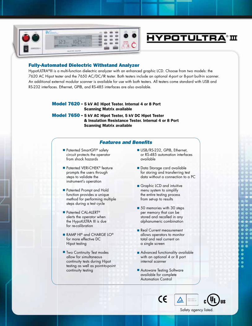
Fully-Automated Dielectric Withstand AnalyzerHypotULTRA®III is a multi-function dielectric analyzer with an enhanced graphic LCD. Choose from two models: the 7620 AC Hipot tester and the 7650 AC/DC/IR tester. Both testers include an optional 4-port or 8-port built-in scanner. An additional external modular scanner is available for use with both testers. All testers come standard with USB and RS-232 interfaces. Ethernet, GPIB, and RS-485 interfaces are also available.
Model 7620 - 5 kV AC Hipot Tester. Internal 4 or 8 Port Scanning Matrix available
Model 7650 - 5 kV AC Hipot Tester, 5 kV DC Hipot Tester & Insulation Resistance Tester. Internal 4 or 8 Port Scanning Matrix available
Safety agency listed.
Patented SmartGFI® safety circuit protects the operator from shock hazards
Patented VERI-CHEK® featureprompts the users through steps to validate the instrument’s operation
Patented Prompt and Holdfunction provides a unique method for performing multiple steps during a test cycle
Patented CAL-ALERT®
alerts the operator whenthe HypotULTRA III is duefor re-calibration
RAMP HI® and CHARGE LO®
for more effective DC Hipot testing
Two Continuity Test modesallow for simultaneous continuity tests during Hipot testing as well as point-to-point continuity testing
USB/RS-232, GPIB, Ethernet, or RS-485 automation interfaces available
Data Storage card availablefor storing and transferring test data without a connection to a PC
Graphic LCD and intuitivemenu system to simplifythe entire testing processfrom set-up to results
50 memories with 30 stepsper memory that can bestored and recalled in any alphanumeric combination
Real Current measurementallows operators to monitor total and real current ona single screen
Advanced functionality availablewith an optional 4 or 8 port internal scanner
Autoware Testing Software available for complete Automation Control
Features and Benefits

Input SpecificationsVoltage 115 / 230 VAC ± 10%, Automatically Selected
Frequency 50/60 Hz ± 5%
Fuse 4 Amp 250 V Slow Blow
Dielectric Withstand Test ModeOutput Rating 5 kV @ 30 mAAC 5 kV @ 10 mADC for 7650 only Output Adjustment Range: 0 – 5000 VAC 0 – 5000 VDC for 7650 only Resolution: 1 V Accuracy: ± (2% of setting + 5 volts) (Can be adjusted during operation. Disabled when key lockout is active.)
Ramp-HI 12 mA peak maximum, ON/OFF selectable
Charge-LO Range: 0.0 - 350.0 µA DC or Auto set
Maximum & Minimum Limits AC Total Range 1: 0.000 – 9.999 mA Resolution: 0.001 mA Range 2: 10.00 – 30.00 mA Resolution: 0.01 mA Accuracy: ± (2% of setting + 2 counts) AC Real Range 1: 0.000 – 9.999 mA Resolution: 0.001 mA Range 2: 10.00 – 30.00 mA Resolution: 0.01 mA Accuracy: (3% of setting + 0.05 mA) All Ranges PF > 0.1 V > 250 VAC DC Range 1: 0.0 – 999.9 μA for 7650 only Resolution: 0.1 μA Range 2: 1000 – 10000 μA for 7650 only Resolution: 1 μA Accuracy: ± (2% of setting + 2 counts)
Arc Detection Range: 1 - 9
Voltage Display Range: 0.00 - 5.00 kV Full Scale Resolution: 10 V Accuracy: ± (2% of setting + 2 counts)
Current Display Auto Range AC Total Range 1: 0.000 mA – 3.500 mA Resolution: 0.001 mA Range 2: 3.00 – 30.00 mA Resolution: 0.01 mA Accuracy: ± (2% of reading + 2 counts) AC Real Range: 0.000 mA – 30.00 mA Resolution: 0.001 mA or 0.01 mA Accuracy: ± (3% of reading + 0.05 mA) All Ranges PF > 0.1 V > 250 VAC
Dielectric Withstand Test Mode (continued) Current Display DC Range 1: 0.0 μA – 350.0 μA for 7650 only Resolution: 0.1 μA Range 2: 0.300 mA – 3.500 mA for 7650 only Resolution: 0.001 mA Range 3: 3.00 mA – 9.99 mA for 7650 only Resolution: 0.01 mA Accuracy: ± (2% of reading + 2 counts)
DC Output Ripple ≤ 4% Ripple rms at 5 kVDC @ 10 mA, Resistive Load
Discharge Time ≤ 200 ms
Maximum Capacitive 1 μF----< 1 kV 0.08 μF----< 4 kVLoad in DC Mode 0.75 μF----< 2 kV 0.04 μF----< 5 kV 0.5 μF----< 3 kV
AC Output Wave Form Sine Wave, Crest Factor = 1.3 - 1.5
Output Frequency Range: 60 or 50 Hz, User Selection Accuracy: ± 0.1%
Output Regulation ± (1 % of output + 5 V) From no load to full load and over input voltage range
Dwell Timer Range: 0.0, 0.4 - 999.9 sec (0 = Continuous)
Ramp Timer Ramp-Up: 0.1 - 999.9 sec Ramp-Down: AC 0.0 - 999.9 sec DC: 0.0, 1.0 - 999.9 sec 0.0=OFF
Ground Continuity Current: DC 0.1 A ± 0.01 A, fixed Max. ground resistance: 1 Ω ± 0.1 Ω, fixed
Ground Fault Interrupt GFI Trip Current: 450 µA max (AC or DC) HV Shut Down Speed: < 1 ms
Insulation Resistance Test Mode (Model 7650 Only)Output Voltage Range: 50 - 1000 VDC Resolution: 1 V Accuracy: ± (2% of reading + 2 counts)
Short Circuit Current Maximum: 12 mA peak
Voltage Display Range: 0 – 1000 V Resolution: 1 V Accuracy: ± (2% of reading + 2 counts)

Insulation Resistance Test Mode Model 7650 Only (continued) Resistance Display Range: 0.05 MΩ - 50000 MΩ (5 Digit, Auto Ranging) Resolution: 500 VDC 1000 VDC
MΩ MΩ MΩ 0.001 0.050 - 9.999 0.100 - 9.999 0.01 1.00 - 99.99 1.00 - 99.99 0.1 10.0 - 999.9 10.0 - 999.9 1 100 - 50000 100 - 50000
Accuracy: 50 – 499 V 0.05 MΩ – 999.9 MΩ ± (7% of reading + 2 counts) 500 – 1000 V 0.10 MΩ – 999.9 MΩ ± (2% of reading + 2 counts) 1000 MΩ – 9999 MΩ ± (5% of reading + 2 counts) 10000 MΩ – 50000 MΩ ± (15% of reading + 2 counts)
Charge-LO Range: 0.000 - 3.500 µA or Auto Set
Maximum and Range: 0.0, 0.05 MΩ – 99.99 MΩMinimum Limits Resolution: 0.01 MΩ Range: 100.0 MΩ – 999.9 MΩ Resolution: 0.1 MΩ Range: 1000 MΩ – 50000 MΩ Resolution: 1 MΩ (Max Limit: 0 = OFF) Accuracy: Same as Resistance Display Accuracy
Ramp Timer Range: Ramp-Up: 0.1 - 999.9 sec Ramp-Down: 0.0, 1.0 - 999.9 sec
Delay Timer Range: 0.0, 1.0 - 999.9 sec 0 = Continuous
Ground Fault GFI Trip Current: 450 µA max Interrupt
HV Shut Down Speed: < 1 ms
Continuity Test ModeOutput Current DC 0.1 A ± 0.01 A Total Resistance*: 0.00-33.0 Ω DC 0.01 A ± 0.001 A Total Resistance*: 31.0-330 Ω DC 0.001 A ± 0.0001 A Total Resistance*: 310-2000 Ω
Resistance Display Range 1: 0.00 – 19.99 Ω Resolution: 0.01 Ω Accuracy: ± (1 % of reading + 0.05 Ω) Range 2: 20.0 – 199.9 Ω Resolution: 0.1 Ω Accuracy: ± (1 % of reading + 0.2 Ω) Range 3: 200 – 2000 Ω Resolution: 1 Ω Accuracy: ± (1 % of reading + 2 Ω)
*Total Resistance of Test Leads, Fixture and DUT.
Continuity Test Mode (continued) Maximum and Range 1: 0.00 – 99.99 ΩMinimum Limits Resolution: 0.01 Ω Accuracy: ± (1% of setting+0.05 Ω) Range 2: 100.0 – 999.9 Ω Resolution: 0.1 Ω Accuracy: ± (1% of setting+0.2 Ω) Range 3: 1000 – 2000 Ω Resolution: 1 Ω Accuracy: ± (1% of setting+2 Ω) (Max Limit: 0 = OFF)
Dwell Timer Range: 0.0, 0.3 - 999.9 sec (0 = Continuous)
Milliohm Offset Range: 0.00 - 10.00 Ω
General SpecificationsMechanical Bench or rack mount (2U height) with tilt up front feet Dimensions (w x h x d) 16.92 x 3.50 x 15.75 in (430 x 89 x 400 mm)
Weight 31.38 Lbs (14.23 kgs) variable with options Interface Standard USB/RS-232 Optional Ethernet, GPIB, Data Storage (RS-485) or Printer Port with Date and Time Stamp Memory 50 memories, 30 steps/memory
Specifications subject to change without notice.
Accredited calibration service available. Includes ISO 17025, ANSI Z540.1-1994, CTL & Denan’s Law requirements.
For more information on testing to a specfic standard, refer back to the Common Safety Standard Reference Chart.

Production Line Dielectric Withstand TestersHypot® III is a bench top Dielectric Withstand tester with an enhanced graphic LCD. Four models are available: the 3705 AC Hipot tester, the 3765 AC/DC Hipot tester, the 3770 AC/DC Hipot tester with built-in Insulation Resistance, and the 3780 500 VA AC Hipot tester. All testers feature an RS-232 interface for entry-level automation.
Model 3705 - 5 kV AC Hipot Tester
Model 3765 - 5 kV AC, 6 kV DC Hipot Tester
Model 3770 - 5 kV AC, 6 kV DC Hipot & Insulation Resistance Tester
Model 3780 - 500 VA (5 kVA @ 100 mA) AC Hipot Tester
Models 3705, 3765 & 3770. Model 3780.
RS-232 interface standardfor entry-level automation
Patented SmartGFI® safetycircuit protects the operatorfrom shock hazards
Patented VERI-CHEK® featureprompts users through stepsto validate the instrument’soperation
Patented CAL-ALERT® featurealerts the operator that the tester is due for re-calibration
Built-in adjustable Continuitytest for checking basiccontinuity
Graphic LCD provides intuitivemenu system to simplify theentire testing process fromset-up to results
Remote Safety Interlock featureprevents the high-voltage frombeing activated without theinterlock enabled
10 Memories with 3 Stepsper memory for storing andrecalling test parameters
PLC Remote Control for simple remote operation
Interconnects with a HYAMP IIIAssociated Research GroundBond tester to form acomplete test system
Digitally controlled arcdetection circuit allows theoperator to program sensitivitylevels for detecting arcs
Minimum and maximum tripsettings for safer and moreaccurate testing
Comes complete with anadapter box for productsterminated in a line cord
Meets 200 mA Short circuitrequirements (Model 3780)
Features and Benefits

3705, 3765, 3770 Specifications
Input SpecificationsVoltage 115/230 VAC ± 10%, user selectable
Frequency 50/60 Hz ± 5%
Fuse 3.15 A, fast acting 250 VAC
Dielectric Withstand Test ModeOutput Rating 5000 V @ 20 mAAC 6000 V @ 7.5 mADC
Voltage Setting Range: 0 - 5.00 kVAC 0 - 6.00 kVDC Resolution: 0.01 kV Accuracy: ± (2% of setting + 5 V)
Maximum Limit AC Range: 0.00 - 20.00 mA Resolution: 0.01 mA DC Range: 0 - 7500 µA Resolution: 1 µA Accuracy: AC and DC ± (2% of setting + 2 counts)
Minimum Limit AC Range: 0.000 - 9.999 mA Resolution: 0.001 mA DC Range: 0.0 - 999.9 µA Resolution: 0.1 µA Accuracy: AC and DC ± (2% of setting + 2 counts)
Arc Detection Range: 0 - 9, 0 disabled
Ground Fault GFI Trip Current: 450 µA max (AC or DC)Interrupt HV Shut Down Speed: < 1ms
Current Display Auto Range AC Range 1: 0.000 - 3.500 mA Resolution: 0.001 mA Range 2: 3.00 - 20.00 mA Resolution: 0.01 mA DC Range 1: 0.0 µA - 350.0 µA Resolution: 1: 0.1 µA Range 2: 0.300 mA - 3.500 mA Resolution: 0.001 mA Range 3: 3.00 mA - 7.50 mA Resolution: 0.01 mA Accuracy: All Ranges ± (2% of reading + 2 counts)
DC Output Ripple ≤ 5% Ripple rms at 6 kVDC @ 7.5 mA, Resistive Load
Discharge Time ≤ 200 ms The maximum capacitive load vs output voltage: 0.20 µF < 1 kV 0.050 µF < 4 kV 0.10 µF < 2 kV 0.040 µF < 5 kV 0.06 µF < 3 kV 0.015 µF < 6 kV
AC Voltage Waveform Sine Wave, Crest Factor = 1.3 - 1.5
Output Frequency Range: 50 or 60 Hz, User Selectable
Output Voltage ± (1% of output + 5 V) from no load to full load and overRegulation input voltage range. Dwell Timer Range: AC 0, 0.3 - 999.9 sec (0 = Continuous) DC 0, 0.4 - 999.9 sec (0 = Continuous) Accuracy: ± (0.1% of reading + 0.05 sec)
Ramp Timer Range: Ramp-Up: 0.1 - 999.9 sec Ramp-Down: AC 0.0 - 999.9 sec DC 1.0 - 999.9 sec (0=OFF) Accuracy: ± (0.1% of reading + 0.05 sec)
Dielectric Withstand Test Mode (continued)Ground Continuity Current DC 0.1 A ± 0.01 A, fixed
Ground Continuity Range: 0.0 Ω - 1.50 Ω Maximum Limit Resolution: 0.01 Ω Minimum Limit Accuracy: ± (3% of setting + 0.02 Ω)
Ground Continuity Range: 0.0 Ω - 0.50 Ω Auto Offset Resolution: 0.01 Ω Accuracy: ± (3% of setting + 0.02 Ω)
Insulation Resistance Test ModeVoltage Setting Range: 30 - 1000 VDC Resolution: 1 V Accuracy: ± (2% of setting + 5 V)
Resistance Display Range: 1 - 9999 MΩ (4 Digit, Auto Ranging) Resolution: 500 VDC - 1000 VDC MΩ MΩ 0.001 1.000 - 9.999 0.01 10.00 - 99.99 0.1 100.0 - 999.9 1 1000 - 9999
Accuracy: ± (2% of reading + 2 counts) at test voltage 500 - 1000 V and 1 - 999.9 MΩ
± (5% of reading + 2 counts) at test voltage 500 - 1000 V and 1000 - 9999 MΩ
± (8% of reading + 2 counts) at test voltage 30 - 500 V and 1 - 1000 MΩ
Maximum Limit Range: 0, 1 - 9999 MΩ (0=OFF) Resolution: 1 MΩ Accuracy: Same as Resistance Display
Minimum Limit Range: 1 - 9999 MΩ Resolution: 1 MΩ Accuracy: Same as Resistance Display
Ramp Timer Range: Ramp-Up: 0.1 - 999.9 sec Ramp-Down: 1.0 - 999.9 sec (0=OFF) Resolution: 0.1 sec Accuracy: ± (0.1% of reading + 0.05 sec)
Delay Timer Range: 0, 0.5 - 999.9 sec (0 = Continuous) Resolution: 0.1 sec Accuracy: ± (0.1% of reading + 0.05 sec)
GFI Trip Current 450 µA max
HV Shut Down Speed < 1 ms
General SpecificationsMechanical Bench or rack mount with tilt up feet
Dimensions (W x H x D) 8.46 x 3.5 x 14.57 in. (215 x 89 x 370 mm) Weight 20.96 lbs (9.53 kgs) Interface RS-232 interface standard for entry-level automation
Memory 10 Memories, 3 steps per memory
Specifications subject to change without notice.

3780 Specifications
Input SpecificationsVoltage 115/230 VAC ± 15%, automatically selected
Frequency 50/60 Hz ± 5%
Fuse 15 Amp, Slow Blow 250 VAC
Dielectric Withstand Test ModeOutput Rating 5000 V @ 100 mAAC
Voltage Setting Range: 0 – 5.00 kVAC Resolution: 0.01 kV Accuracy: ± (2% of setting + 0.01 kV) (Adjustable during operation. Disable when key lockout is active.)
Maximum Limit AC Range: 0.00 – 99.99 mA Resolution: 0.01 mA Accuracy: ± (2% of setting + 6 counts)
Minimum Limit AC Range: 0.000 – 9.999 mA Resolution: 0.001 mA Accuracy: ± (2% of setting + 6 counts)
Arc Detection Range: 0 - 9, 0 disabled
Ground Fault GFI Trip Current: 450 µA maxInterrupt HV Shut Down Speed: < 1ms
Current Display Auto Range AC Range 1: 0.000 mA – 3.500 mA Resolution: 0.001 mA Accuracy: ± (2% of setting + 2 counts) Range 2: 3.00 – 99.99 mA Resolution: 0.01 mA Accuracy: ± (2% of setting + 6 counts)
AC Voltage Wave Form Sine Wave, Crest Factor = 1.3 – 1.5
Output Frequency Range: 50 or 60 Hz, User Selectable Accuracy: ± 0.1%
Output Voltage ± (1 % of output + 5 V)Regulation from no load to full load and over input voltage range. Dwell Timer Range: 0, 0.3 – 999.9 sec (0 = Constant) Resolution: 0.1 sec Accuracy: ± (0.1% of reading + 0.05 sec)
Ramp Timer Range: Ramp-Up: 0.1 - 999.9 sec Ramp-Down: AC 0.0 - 999.9 sec Resolution: 0.1 sec Accuracy: ± (0.1% of reading + 0.05 sec)
Ground Continuity Current DC 0.1 A ± 0.01 A, fixed
Ground Continuity Range: 0.0 Ω - 1.50 Ω Maximum Limit Resolution: 0.01 Ω Minimum Limit Accuracy: ± (3% of setting + 0.02 Ω)
Ground Continuity Range: 0.0 Ω - 0.50 Ω Auto Offset Resolution: 0.01 Ω Accuracy: ± (3% of setting + 0.02 Ω)
Output Short Circuit > 200 mA Current
General SpecificationsMechanical Bench or rack mount with tilt up feet
Dimensions (W x H x D) 16.93 x 5.24 x 13.78 in. (430 x 133 x 350 mm) Weight 49 lbs (23 kgs) Interface RS-232 interface standard for entry-level automation
Memory 10 Memories, 3 steps per memory
Specifications subject to change without notice.
Accredited calibration service available. Includes ISO 17025, ANSI Z540.1-1994, CTL & Denan’s Law requirements.
For more information on testing to a specfic standard, refer back to the Common Safety Standard Reference Chart.

Production Line Ground Bond TestersHYAMP® III is a microprocessor controlled Ground Bond tester with an enhanced graphic LCD. Three models are available: the 3130 with 30 Amp output, the 3140 with 40 Amp output and the 3160 with 60 Amp output. Model 3130 also has an optional external RS-232 interface. HYAMP III can be interconnected with Hypot III to form a complete test system.
Model 3130 - 30 Amp Ground Bond Tester
Model 3140 - 40 Amp Ground Bond Tester
Model 3160 - 60 Amp Ground Bond Tester
Safety agency listed.
External RS-232 interface available for entry-level automation (Model 3130)
Patented VERI-CHEK® featureprompts users through stepsto validate the instrument’soperation
Graphic LCD provides intuitivemenu system to simplify theentire testing process fromset-up to results
Patented CAL-ALERT® featurealerts the operator that thetester is due for re-calibration
PLC Remote Control allowsoperators to remotely control the Ground Bond tester
10 Memories with 3 Stepsper memory for storing andrecalling test parameters
Interconnects with anAssociated Research Hipottester to form a completetest system
4 wire measurement andmilliohm offset for accurateGround Bond test results
Electronic Dwell timer formore consistent andreliable testing
Adjustable output current and milliohm trip ranges to meet all safety agency specifications for Ground Bond test requirements
Features and Benefits

Input SpecificationsVoltage 115/230 VAC ± 10%, user selectable
Frequency 50/60 Hz ± 5%
Fuse - 3130 6.3 A, Slow Blow 250 VAC
Fuse - 3140 10 A, Slow Blow 250 VAC
Fuse - 3160 15 A, Slow Blow 250 VAC
Ground Bond Test ModeOutput Rating Current 3130: 1.00 - 30.00 AAC Voltage 3130: 6 VAC, fixed
Current 3140: 1.00 - 40.00 AAC Voltage 3140: 8 VAC, fixed
Current 3160: 1.00 - 60.00 AAC Voltage 3160: 9 VAC, fixed Resolution: 0.01 A Regulation: ± (2% of setting + 0.02 A)
Output Frequency Range: 50 / 60 Hz, User Selectable
Dwell Time Setting Range: 0 and 0.5 - 999.9 secs 0 for continuous running Resolution: 0.1 sec Accuracy: ± (0.1% of setting + 0.05 secs)
Maximum & Minimum Range 3130: 0 - 120 mΩ for 1 - 30.00 ALimits 0 - 510 mΩ for 1 - 10.00 A Accuracy 3130: ± (2% of setting + 2 mΩ) Range 3140: 0 - 150 mΩ for 30.01 - 40.00 A 0 - 200 mΩ for 10.01 - 30.00 A 0 - 600 mΩ for 1.00 - 10.00 A Accuracy 3140: ± (3% of setting + 3 mΩ) Range 3160: 0 - 150 mΩ for 30.01 - 60.00 A 0 - 300 mΩ for 15.01 - 30.00 A 0 - 600 mΩ for 1.00 - 15.00 A Accuracy 3160: ± (3% of setting + 3 mΩ)
Offset Capability Range: 0 - 100 mΩ Resolution: 1 mΩ Accuracy: ± (2% of setting + 2 mΩ)
Current Display 3130 Range: 0.00 - 30.00 A Resolution: 0.01 A / step Accuracy: ± (3% of reading + 0.03 A)
Current Display 3140 Range: 0.00 - 40.00 A Resolution: 0.01 A Accuracy: ± (3% of reading + 0.03 A)
Current Display 3160 Range: 0.00 - 60.00 A Resolution: 0.01 A Accuracy: ± (3% of reading + 0.03 A)
Ohmmeter Display 3130 Range: 0 - 510 mΩ Resolution: 1 mΩ / step Accuracy: ± (2% of reading + 2 mΩ)
Ground Bond Test Mode (Continued)Ohmmeter Display 3140 Range: 0 - 150 mΩ for 30.01 - 40.00 A 0 - 200 mΩ for 10.01 - 30.00 A 0 - 600 mΩ for 6.00 - 10.00 A Resolution: 1 mΩ Accuracy: ± (2% of reading + 2 mΩ) Range: 0 - 600 mΩ for 1.00 - 5.99 A Resolution: 1 mΩ Accuracy: ± (3% of reading + 3 mΩ)
Ohmmeter Display 3160 Range: 0 - 150 mΩ for 30.01 - 60.00 A 0 - 300 mΩ for 15.01 - 30.00 A 0 - 600 mΩ for 6.00 - 15.00 A Resolution: 1 mΩ Accuracy: ± (2% of reading + 2 mΩ) Range: 0 - 600 mΩ for 1.00 - 5.99 A Resolution: 1 mΩ Accuracy: ± (3% of reading + 3 mΩ)
Timer Display Range: 0.0 - 999.9 secs Resolution: 0.1 secs Accuracy: ± (0.1% of reading + 0.05 secs)
General SpecificationsMechanical Bench or rack mount with tilt up feet.
Dimensions 3130 (W x H x D) 8.5 x 4.0 x 15.5 in. (216 x 103 x 390 mm) includes feet
Dimensions 3140 (W x H x D) 8.5 x 4.0 x 16.9 in. (216 x 103 x 430 mm) includes feet
Dimensions 3160 (W x H x D) 16.9 x 5.1 x 15.7 in. (430 x 130 x 400 mm) includes feet
Weight 3130 19.15 lbs (8.7 kgs)
Weight 3140 30.9 lbs (14 kgs)
Weight 3160 49.40 lbs (22.40 kgs)
Remote Control & The following input and output signals are providedSignal Output through two 9 pin D type connectors: 1. Remote control: Test, Reset, Interlock, and Withstand Processing 2. Remote recall of memory program #1, #2, and #3 3. Outputs: Pass, Fail, Test-in-process, Start Out and Reset Out
Program Memory 10 Memories, 3 steps per memory
Interface External RS-232 interface for Model 3130
Specifications subject to change without notice.
Accredited calibration service available. Includes ISO 17025, ANSI Z540.1-1994, CTL & Denan’s Law requirements.
For more information on testing to a specfic standard, refer back to the Common Safety Standard Reference Chart.

Fully-Automated Line Leakage TesterThe 620L is a stand alone Line Leakage tester with an enhanced graphic LCD which automates leakage testing in production and laboratory environments. The 620L is configured for up to 40 Amps of current draw for DUT input power. It is designed to test to most safety agency standards for Line Leakage testing. The 620L comes standard with USB and RS-232 interfaces. Ethernet, GPIB, and RS-485 interfaces are also available.
Model 620L - Fully-Automated Line Leakage Tester
Safety agency listed.
Test operators can configurethe 620L to perform all 8 required Line Leakage tests
Leakage current readings canbe monitored using both PEAKand RMS measurements
Most common measuringdevices (MD’s) are already incorporated into the instrument’s intuitivemenu system
50 Memories with 30 stepsper memory can be stored and recalled in any alphanumeric combination
Compact 3U RackMount Design
Optional Functional RunTesting for additional measurements
Interconnection to APT BrandAC Power Source
Interconnection to SC6540Modular Scanner provides automated control of multiple test points
Graphic LCD and intuitive menu system to simplify the entire testing process
Patented CAL-ALERT® alerts the operator that the 620L is due for re-calibration
Handles up to 40 Amp maximum continuous DUT Current
Optional cold resistancemeasurement capability
USB/RS-232, GPIB, Ethernet, or RS-485 automation interfaces available
Easily Interconnect to any automated Associated Research Hipot Tester
Autoware Testing Software available for complete Automation Control
Features and Benefits
APT AC Power Source Compatible
www.aspowertechnologies.com
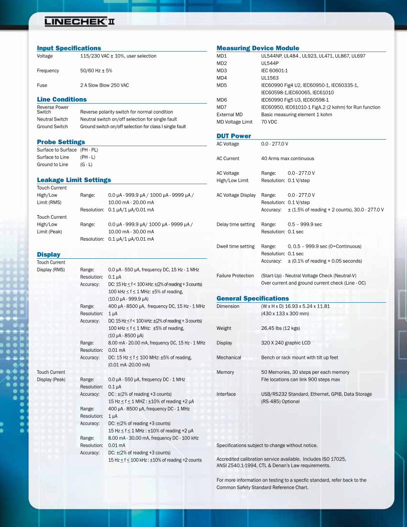
Input SpecificationsVoltage 115/230 VAC ± 10%, user selection
Frequency 50/60 Hz ± 5%
Fuse 2 A Slow Blow 250 VAC
Line ConditionsReverse Power Switch Reverse polarity switch for normal conditionNeutral Switch Neutral switch on/off selection for single fault Ground Switch Ground switch on/off selection for class I single fault
Probe SettingsSurface to Surface (PH - PL)Surface to Line (PH - L)Ground to Line (G - L)
Leakage Limit SettingsTouch CurrentHigh/Low Range: 0.0 µA - 999.9 µA / 1000 µA - 9999 µA / Limit (RMS) 10.00 mA - 20.00 mA Resolution: 0.1 µA/1 µA/0.01 mATouch CurrentHigh/Low Range: 0.0 µA - 999.9 µA/ 1000 µA - 9999 µA / Limit (Peak) 10.00 mA - 30.00 mA Resolution: 0.1 µA/1 µA/0.01 mA
DisplayTouch CurrentDisplay (RMS) Range: 0.0 µA - 550 µA, frequency DC, 15 Hz - 1 MHz Resolution: 0.1 µA Accuracy: DC: 15 Hz < f < 100 kHz: ±(2% of reading + 3 counts) 100 kHz < f < 1 MHz: ±5% of reading, (10.0 µA - 999.9 µA) Range: 400 µA - 8500 µA, frequency DC, 15 Hz - 1 MHz Resolution: 1 µA Accuracy: DC: 15 Hz < f < 100 kHz: ±(2% of reading + 3 counts) 100 kHz < f < 1 MHz: ±5% of reading, (10 µA - 8500 µA) Range: 8.00 mA - 20.00 mA, frequency DC, 15 Hz - 1 MHz Resolution: 0.01 mA Accuracy: DC: 15 Hz < f < 100 MHz: ±5% of reading, (0.01 mA -20.00 mA)Touch CurrentDisplay (Peak) Range: 0.0 µA - 550 µA, frequency DC - 1 MHz Resolution: 0.1 µA Accuracy: DC : ±(2% of reading +3 counts) 15 Hz < f < 1 MHZ : ±10% of reading +2 µA Range: 400 µA - 8500 µA, frequency DC - 1 MHz Resolution: 1 µA Accuracy: DC: ±(2% of reading +3 counts) 15 Hz < f < 1 MHz : ±10% of reading +2 µA Range: 8.00 mA - 30.00 mA, frequency DC - 100 kHz Resolution: 0.01 mA Accuracy: DC: ±(2% of reading +3 counts) 15 Hz < f < 100 kHz : ±10% of reading +2 counts
Measuring Device ModuleMD1 UL544NP, UL484 , UL923, UL471, UL867, UL697MD2 UL544PMD3 IEC 60601-1MD4 UL1563MD5 IEC60990 Fig4 U2, IEC60950-1, IEC60335-1, IEC60598-1,IEC60065, IEC61010MD6 IEC60990 Fig5 U3, IEC60598-1MD7 IEC60950, IEC61010-1 FigA.2 (2 kohm) for Run functionExternal MD Basic measuring element 1 kohmMD Voltage Limit 70 VDC
DUT PowerAC Voltage 0.0 - 277.0 V
AC Current 40 Arms max continuous
AC Voltage Range: 0.0 - 277.0 VHigh/Low Limit Resolution: 0.1 V/step
AC Voltage Display Range: 0.0 - 277.0 V Resolution: 0.1 V/step Accuracy: ± (1.5% of reading + 2 counts), 30.0 - 277.0 V
Delay time setting Range: 0.5 – 999.9 sec Resolution: 0.1 sec
Dwell time setting Range: 0, 0.5 – 999.9 sec (0=Continuous) Resolution: 0.1 sec Accuracy: ± (0.1% of reading + 0.05 seconds)
Failure Protection (Start-Up) - Neutral Voltage Check (Neutral-V) Over current and ground current check (Line - OC)
General SpecificationsDimension (W x H x D) 16.93 x 5.24 x 11.81 (430 x 133 x 300 mm)
Weight 26.45 lbs (12 kgs) Display 320 X 240 graphic LCD Mechanical Bench or rack mount with tilt up feet
Memory 50 Memories, 30 steps per each memory File locations can link 900 steps max
Interface USB/RS232 Standard, Ethernet, GPIB, Data Storage (RS-485) Optional
Specifications subject to change without notice.
Accredited calibration service available. Includes ISO 17025, ANSI Z540.1-1994, CTL & Denan’s Law requirements.
For more information on testing to a specfic standard, refer back to the Common Safety Standard Reference Chart.

High Voltage and High Current Modular Scanning MatrixThe SC6540 modular scanner is designed to automate multi-point and multi-product testing when using OMNIA, HypotULTRA III, LINECHEK II or HypotMAX testers 7700 and 7704. There are 10 different configurations available that are built off of two basic scanning configurations determined by the power module. A master scanner (M) is configured with its own power module and controlled directly through automation software. It is available with either a USB/RS-232, GPIB, or Ethernet Interface. A slave scanner (S) is configured without a power module and is controlled either by a master scanner or the electrical safety tester. The SC6540 can be configured with 8 HV (high voltage), 16 HV, 8 HV and 8 GB (Ground Bond), 8 GB or 16 GB testing channels. The patented modular design provides a flexible testing solution that is configurable to a manufacturer’s needs. Designed to interconnect with most of our automated electrical safety testers, the SC6540 allows for automated multi-point or multi-product safety testing. This is an ideal solution for applications such as transformers, motors, cables or any DUT that requires tests between various points.
Safety agency listed.
Configurable scanning matrix
Multi-point or multi-product testing capabilities
Automation interfaces for Autoware® control
Point-to-point continuity tests Compatible with Hipot, Ground Bond, Line Leakage and Insulation Resistance Tests
Up to 16 high voltage switching channels on a single scanner
High current outputs rated up to 40 Amps
Up to 80 testing points from a single power source
Compact 2U rack mount design
Features and Benefits
Model SC6540 HNM - 8 Channel High Voltage Scanner
Model SC6540 HHM - 16 Channel High Voltage Scanner
Model SC6540 HGM - 8 Channel High Voltage Scanner 8 Channel High Current Scanner
Model SC6540 GNM - 8 Channel High Current Scanner
Model SC6540 GGM - 16 Channel High Current Scanner

Modular Scanning Matrix SpecificationsInput (Master only) 115 VAC (+/- 10%), 50/60 Hz, single phase 230 VAC (+/- 10%), 50/60 Hz, single phase User selectable
Fuse (Master only) 250 V/2 A/fast-blow
PC Control (Master only) Choice of Ethernet, GPIB or USB/RS-232
Scanner Control Master: one scanner bus output controls up to 4 additional slaves Slave: one output and one input
Maximum HV Rating 5 kV AC and DC
Maximum HC Rating 40 Amps
No. of Possible Channels 8 or 16
HV Output Terminations 100 ft. reel HV cable rated for up to 30 kV with 8 HV connectors
GND Output Terminations 20 terminals provided, to accept 10/12 AWG hook-up wire (user supplied wire)
Temperature 32˚ - 104˚ F (0˚ - 40˚ C)
Humidity 0 - 80%
Altitude 6560 ft. (2000 m)
Dimensions 2U with tilt-up front feet (WxHxD) 17 x 4.07 x 12.96 in. (432 x 103 x 329 mm)
Weight Master: 20.05 lbs. max. (9.09 kgs) (with 2 high voltage modules) Slave: 15.45 lbs. max. (7.01 kgs) (with 2 high voltage modules)
ConfigurationsThe modular design allows for a variety of configurations. In addition to master or slave configurations, the scanners can also be set-up with the following configurations, 8 or 16 high voltage testing channels, 8 high voltage and ground bond testing channels, and 8 or 16 ground bond testing channels.
*Also available in slave configuration. Specifications subject to change without notice.
Accredited calibration service available. Includes ISO 17025, ANSI Z540.1-1994, CTL & Denan’s Law requirements.
For more information on testing to a specfic standard, refer back to the Common Safety Standard Reference Chart.”
The different configurations (shown right) are indicated by the following alpha designators
M = Master ScannerH = 8 High Voltage ChannelsHH = 16 High Voltage ChannelsG = 8 Ground Bond ChannelsGG = 16 Ground Bond ChannelsN = Empty Module S = Slave
Model SC6540 HNM*8 Channel High Voltage Scanner
Model SC6540 HHM*16 Channel High Voltage Scanner
Model SC6540 GNM*8 Channel High Current Scanner
Model SC6540 GGM*16 Channel High Current Scanner
Model SC6540 HGM*8 Channel High Voltage Scanner8 Channel High Current Scanner
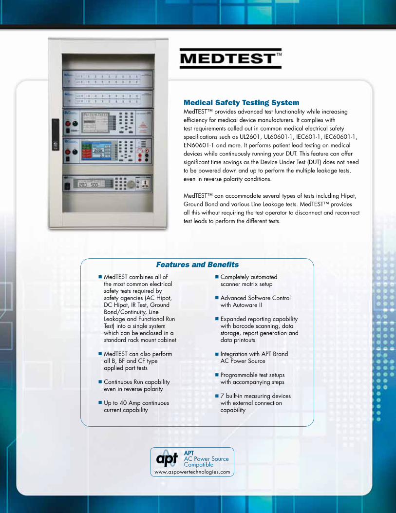
Medical Safety Testing SystemMedTEST™ provides advanced test functionality while increasing efficiency for medical device manufacturers. It complies with test requirements called out in common medical electrical safety specifications such as UL2601, UL60601-1, IEC601-1, IEC60601-1, EN60601-1 and more. It performs patient lead testing on medical devices while continuously running your DUT. This feature can offer significant time savings as the Device Under Test (DUT) does not need to be powered down and up to perform the multiple leakage tests, even in reverse polarity conditions.
MedTEST™ can accommodate several types of tests including Hipot, Ground Bond and various Line Leakage tests. MedTEST™ provides all this without requiring the test operator to disconnect and reconnect test leads to perform the different tests.
MedTEST combines all of the most common electrical safety tests required by safety agencies (AC Hipot, DC Hipot, IR Test, Ground Bond/Continuity, Line Leakage and Functional Run Test) into a single system which can be enclosed in a standard rack mount cabinet MedTEST can also perform all B, BF and CF type applied part tests
Continuous Run capability even in reverse polarity
Up to 40 Amp continuouscurrent capability
Features and Benefits
Completely automatedscanner matrix setup
Advanced Software Controlwith Autoware II
Expanded reporting capability with barcode scanning, data storage, report generation and data printouts
Integration with APT BrandAC Power Source
Programmable test setupswith accompanying steps
7 built-in measuring devices with external connection capability
APT AC Power Source Compatible
www.aspowertechnologies.com

MedTEST is designed to run with our Autoware software. This enables the user to have complete computer control of the test system. MedTEST will connect to a PC through a host of PC interfaces including USB/RS-232, Ethernet or GPIB.
Autoware allows the MedTEST system to be remotely programmed and set-up. It provides programmable memories and steps which can be saved and recalled resulting in more efficient testing. Each test memory can store up to 30 test steps which can be configured to perform any of the safety tests. All these test steps can be linked together to form a complete automated test sequence. Further, all test memories can be linked together creating a virtually unlimited number of test steps. Complete data capture is also easily achieved with the MedTEST system. Test results for every single test can be viewed in a statistical format, exported for database archiving, or even directly sent to a print report.
The MedTEST system is designed to provide you with a custom test solution. It can be configured to meet almost any application and since the configuration incorporates existing Associated Research testers you don’t end up paying for a custom solution and still maintain the ability to meet ever changing demands for your test equipment.
The MedTEST configuration begins with the Associated Research 620L for Line Leakage Testing functionality, The OMNIA 8204 for Hipot and Ground Bond testing functionality and an Associated Power Technologies AC power source.
Depending on the requirements of your application, MedTEST can be configured to perform patient lead tests on a virtually endless amount of points.
MedTEST TM provides advanced test functionalitywhile increasing efficiency for medical device manufacturers.
With its advanced functionality and the ability to improve test efficiency,MedTEST is the most cost-effective solution on the market!

Dielectric Withstand Test ModeOutput Rating 5 kV @ 50 mAAC 5 kV @ 20 mADC
Voltage Setting Range: 0-5000 VAC 0-5000 VDC Resolution: 1 V Accuracy: ± (2% of setting + 5 V)
HI and LO-Limit AC Total Range: 0.000-9.999 mA Resolution: 0.001 mA Accuracy: ± (2% of setting + 2 counts) Range: 10.00 - 50.00 mA Resolution: 0.01 mA Accuracy: ± (2% of Setting + 2 Counts) AC Real Range: 0.000-9.999 mA Resolution: 0.001 mA Accuracy: ± (3% of Setting + 50 µA) Range: 10.00 - 50.00 mA Resolution: 0.01 mA Accuracy: ± (3% of Setting + 50 µA) DC Range: 0.00 - 999.9 µA Resolution: 0.1 µA Accuracy: ± (2% of Setting + 2 Counts) Range: 1000 - 20000 µA Resolution: 1 µA Accuracy: ± (2% of Setting + 2 Counts)
Ramp HI >20 mA peak maximum, ON/OFF selectable
Charge LO Range: 0.000 - 350 µA or Auto Set
DC Output Ripple ≤ 4% Ripple rms at 5 kVDC @ 20 mA, Resistive Load
Discharge Time < 50 msec for no load, < 100 msec for capcitor load (all capacitance values in MAX load spec below)
Maximum 1 µF < 1 kV 0.08 µF < 4 kVCapacitive Load 0.75 µF < 2 kV 0.04 µF < 5 kV 0.50 µF < 3 kV
Output Frequency 50/60 Hz ± 0.1% , User Selection, 400/800 Hz OptionAC Output Waveform Sine Wave, Crest Factor = 1.3 - 1.5
Output Regulation ± (1% of output + 5 V) from no load to full load and over input voltage range
Dwell Timer AC 0.4 - 999.9 sec (0 = Continuous) DC 0.3 - 999.9 sec (0 = Continuous)
Ramp Timer Ramp-Up AC: 0.1 - 999.9 Ramp-Down AC: 0.0-999.9 Ramp-Up DC: 0.4 - 999.9 Ramp-Down DC: 0.0, 1.0-999.9
Ground Continuity Current: DC 0.1 A ± 0.01 A, fixed Max. Ground Resistance: 1 Ω ± 0.1 Ω, fixed
Ground Fault Interrupt GFI Trip Current: 5.0 mA max HV Shut Down Speed: < 1 ms
Line ConditionsPower Switch Reverse polarity switch for normal condition
Neutral Switch Neutral switch on/off selection for single fault
Ground Switch Ground switch on/off selection for class I single fault
Probe SettingsSurface to Surface (PH - PL)Surface to Line (PH - L)Ground to Line (G - L)
Leakage Limit SettingsTouch CurrentHigh/Low Range: 0.0 µA - 999.9 µA / 1000 µA - 9999 µA / Limit (RMS) 10.00 mA - 20.00 mA Resolution: 0.1 µA / 1 µA / 0.01 mATouch CurrentHigh/Low Range: 0.0 µA - 999.9 µA / 1000 µA - 9999 µA /Limit (Peak) 10.00 mA - 30.00 mA Resolution: 0.1 µA / 1 µA / 0.01 mA
Measuring Device ModuleMD1 UL544NP, UL484 , UL923, UL471, UL867, UL697MD2 UL544PMD3 IEC 60601-1 MD4 UL1563MD5 IEC60990 Fig4 U2, IEC60950-1, IEC60335-1, IEC60598-1, IEC60065, IEC61010MD6 IEC60990 Fig5 U3, IEC60598-1MD7 IEC60950, IEC61010-1 FigA.2 (2 kohm) for Run functionExternal MD Basic measuring element 1 kohmMD Voltage Limit 70 VDC
DUT PowerAC Voltage 0.0 - 277.0 V
AC Current 40 Arms max continuous
AC VoltageHigh/Low Limit Range: 0.0 - 277.0 V Resolution: 0.1 V/step
AC Voltage Display Range: 0.0 - 277.0 V Resolution: 0.1 V/step Accuracy: ± (1.5% of reading + 2 counts), 30.0 - 277.0 V
Delay time setting Range: 0.5 – 999.9 sec
Resolution: 0.1 sec
Dwell time setting Range: 0, 0.5 – 999.9 sec (0=Continuous) Resolution: 0.1 sec Accuracy: ± (0.1% of reading + 0.05 seconds)
Failure Protection (Start-Up) - Neutral Voltage Check (Neutral-V) Over current and ground current check (Line - OC)

Continuity Test ModeOutput Current DC 0.1 A ± 0.00001 A
Resistance Display Range: 0.00 – 10000.00 Ω
HI and LO-Limit 0.00 – 10000 Ω
Dwell Timer Range: 0.0, 0.3 - 999.9 sec (0 = Continuous)
Milliohm Offset Range: 0.00 – 10.00Ω
Ground Bond Test ModeOutput Voltage Range: 3.00 - 8.00 VAC
Output Frequency 50/60 Hz ± 0.1% , User Selection
Output Current Range: 1.00 - 40.00 A Resolution: 0.01 A Accuracy: ± (2 % of setting + 2 counts)
Output Regulation ± (1% of output + 0.02A), Within maximum load limits, and over input voltage range.
Maximum Loading 1.00 - 10.00 A, 0 - 600 mΩ 10.01 - 30.00 A, 0 - 200 mΩ 30.01 - 40.00 A, 0 - 150 mΩ
HI and LO-Limit Range: 0 - 150 for 30.01 - 40.00 A Range: 0 - 200 for 10.01 - 30.00 A Range: 0 - 600 for 6.00 - 10.00 A Range: 0 - 600 for 5.99 - 1.00 A Resolution: 1 mΩ Accuracy: 6.00 - 40.00 A, ± (2% of setting + 2 Counts) Accuracy: 1.00 - 5.99 A, ± (3% of setting + 3 Counts)
Milliohm Offset Range: 0 - 200 mΩ
General SpecificationsInterface USB/RS-232 Standard, Ethernet, GPIB Optional
Safety Built-in SmartGFI® circuit
Memory 50 memories, 30 step/memory
Insulation Resistance Test ModeOutput Voltage Range: 30 - 1000 VDC
Charging Current Maximum >20 mA peak
HI and LO-Limit Range: 0.05-99.99 MΩ Resolution: 0.01 MΩ Range: 100.0 - 999.9 MΩ Resolution: 0.1 MΩ Range: 1000 - 50000 MΩ Resolution: 1 MΩ
Charge-LO 0.000 - 3.500 µA or Auto Set
Ramp Timer Ramp-Up: 0.1 - 999.9 secs Ramp-Down: 0.0, 1.0 -999.9 secs
Dwell Timer 0, 0.5 - 999.9 (0=Continuous)
Delay Timer 0.5 - 999.9 secs
Ground Fault Interrupt GFI Trip Current: 5.0 mA max HV Shut down Speed: < 1 ms
AC Power SourceAC Power Source Up-to 4 kVA compatible power sources available.
Configuration AC Power Source configuration depends on application.
MedTEST hardware is configured for testing products with one side of the supply mains at earth potential (Fig 10 UL60601-1).
MedTEST hardware is configured for unbalanced 220 V DUT input power.
Specifications subject to change without notice.
Custom Configurations available. Contact us for details.
For more information on testing to a specfic standard, refer back to the Common Safety Standard Reference Chart.

System 3400The system 3400 is a manual electrical safety test system. The base system includes: HYAMP® III 3140, 40 Amp Ground Bond tester, interconnect cables and a receptacle box with a choice of four Hypot® III Dielectric Withstand testers.
System 3100The system 3100 is a manual electrical safety test system. The base system includes: HYAMP® III 3130, interconnect cables and a receptacle box with a choice of four Hypot® III Dielectric Withstand testers.
System 6000The system 6000 is a manual electrical safety test system. The base system includes: HYAMP® III 3160, 60 Amp Ground Bond tester and interconnect cables with a choice of four Hypot® III Dielectric Withstand testers.
Safety agency listed.
Model 34-05 - HYAMP® III 3140 with Hypot® III 3705
Model 34-65 - HYAMP® III 3140 with Hypot® III 3765
Model 34-70 - HYAMP® III 3140 with Hypot® III 3770
Model 34-80 - HYAMP® III 3140 with Hypot® III 3780
Model 31-05 - HYAMP® III 3130 with Hypot® III 3705
Model 31-65 - HYAMP® III 3130 with Hypot® III 3765
Model 31-70 - HYAMP® III 3130 with Hypot® III 3770
Model 31-80 - HYAMP® III 3130 with Hypot® III 3780
Model 60-05 - HYAMP® III 3160 with Hypot® III 3705
Model 60-65 - HYAMP® III 3160 with Hypot® III 3765
Model 60-70 - HYAMP® III 3160 with Hypot® III 3770
Model 60-80 - HYAMP® III 3160 with Hypot® III 3780

Electrical Safety Compliance SoftwareSoftware that works in tandem with Associated Research, Inc.Testers to automate a testing workstation. Autoware allows you to capture, store and analyze test data and results!
Autoware II is a user friendly software solution designed to work with Associated Research’s OMNIA II, OMNIA, LINECHECK II, and SC6540 instruments. Autoware II software automates testing procedures and increases production line efficiency by providing the ability to manage and remotely program instruments. Autoware II allows for the automatic loading of test files and the ability to drag and drop test files to and from the instrument and PC. It also allows for the operation and monitoring of the instrument in real time. Autoware II provides the backup assurance manufacturers need to prove their equipment meets electrical safety requirements established by safety agencies by allowing for statistical analysis, advanced print out, and archival of test data.
Autoware II is also compatible with Associated Power Technologies, Inc.’s 6000, 7000 & 300XAC series of AC power sources for RUN and LLT testing.
Autoware S9870 is used in tandem with Associated Research Inc.’s QUADCHEK II, HypotMAX, HypotULTRA III, LINECHEK and RUNCHEK series of instruments.
Features and BenefitsChoice of Ethernet, USB/RS-232 or GPIB communication interfaces
Graphical Drag and Drop User Interface
Batch Processing
Automated Instrument Identification and setup
Pre-configured Instrument Verification Files
Customizable Menu Display
Two Versions Available (Full or Data Logging)
Intelligent Error Handling
Control Panel Screen Results Screen System Settings

38081 - High Voltage Probe
38082 - Return ProbeRetractable high voltage and return probes for safe high voltage testing up to 5 kV. The probe tips allow for safe and easy testing by extending and retracting with the press of a button.
38814 - High Voltage Pistol Probe with Switch
This high voltage test gun has a dual action test trigger that controls the retractable probe tip and activates the high voltage output of the instrument. The unique ergonomic shape makes this probe easy and comfortable to use.
38539 - 2 Wire 40 Amp Ground Bond Probe38538 - 4 Wire 40 Amp Ground Bond Probe
These fixed tip probes allow for easy contact with the grounding points of the DUT. Separate test buttons to use in various positions. Three different tip styles included.
35822 - Foot Switch
Ideal for use in applications where an operator needs to perform a test while using test probes.
39067 - Test Enclosure
This DUT Enclosure is designed with a safety interlock that will eliminate the potential for electrical shock when used correctly. The interlock will disable the high voltage if the enclosure door is open. The DUT Enclosure is designed to be used with all interlocked Associated Research Hipot testers.
39077 - Test CabinetThis test cabinet is used with any Associated Research rack mountable tester.
39001 - Small Shipping Case39085 - Large Shipping Case
We offer a large shipping case and a small shipping case each with custom inserts to protect your Associated Research tester. They are used for the shipping and transportation of an Associated Research tester.
CBLSR-05M - Magnetic Hipot Return Cable
CBLHR-05M - Magnetic Ground Bond Return Cable
We have available test leads that are terminated in a magnetic tip that allow for easy application of the test lead to the DUT. These test leads are available in lengths from 5 to15 feet.
36541, 38482, 36544, 38777, 38578 - Adaptor Box
Adapter boxes allow for safe and easy testing of line cord terminated products. All necessary connections are made within the adapter box helping to avoid connection errors, with configurations that satisfy a variety of needs.
A Powerful Online Resource!- Convenient Online Ordering- Request a Video Demonstration- Schedule a Calibration- See New Product Introductions- View Product Specials and Promotions- Join our Informative Seminars & Webinars!- Sign-up for our Feature-packed Newsletter- Take a Virtual Tour of our Instruments- View Instructional Videos

We have local sales offices throughout the world to serve you more efficiently.To find your nearest representative visit the “Local Sales Offices” section of our web site at www.asresearch.com or call us toll-free at 1-800-858-8378
13860 West Laurel Drive,Lake Forest, IL U.S.A. 60045Tel: +1-847-367-4077 Fax: +1-847-367-4080E-mail: [email protected] more information visit us at www.asresearch.comor call us toll-free at 1-800-858-TEST(8378)
VER 0112
Pallars 65-7108018 Barcelona, Spain
T. (+34) 93 320 80 55F. (+34) 93 320 80 56
www.wavecontrol.com
DISTRIBUIDOR EN ESPAÑA Y PORTUGAL: