the impact of geotechnical factors on the secondary ... final report.pdf · the impact of...
TRANSCRIPT

Safety In Mines Research Advisory Committee
Final Project Report
The impact of geotechnical factors onthe secondary extraction of coal in the
Witbank and Northern HighveldCoalfields, specifically related to safety
L S Jeffrey
Research agency: CSIR, Mining TechnologyProject number: COL810Date: April 2002

i
Executive Summary
The literature review identified geotechnical factors impacting on unplanned secondary coal
extraction. These factors are grouped into nine broad classes of factors; namely,
stratigraphy, rock /coal engineering properties, spontaneous combustion, discontinuities,
igneous intrusions, collapse of previous workings, hydrology, stress environment and the
primary mining parameters. It was found that for underground extraction stratigraphy,
igneous intrusions, collapse of previous workings and the stress environment have the most
impact on the rock mass behaviour (i.e. the roof caving and rock burst potential, rib and pillar
stability, floor heave and roof / surface subsidence), roof support (both on a mine- and panel-
scale) and explosions/ignitions (gas conditions, as well as spontaneous combustion). For
open cast extraction the stratigraphy, igneous intrusions, collapse of previous workings, the
stress environment and the primary mining parameters had greatest impact on the rock mass
behaviour (slope and high wall stability and floor heave) and explosions / ignitions.
Selected collieries were then visited in order to quantify the impact the factors may have on
resource/reserve estimation and safety. This resulted in the identification of additional
geotechnical factors with impact on secondary extraction, as well as a tenth class of factors –
secondary mining parameters. The factors impacting on safety, as well as which exploitation
phase (i.e. mine planning and/or production) they affect, were identified. These factors
belong to all ten classes; those with most impact are primary and secondary mining factors
and stratigraphy. The collieries quantified the factors according to their impact on safety; a
quantification of 10 implies the factor has a high negative impact, while a quantification of 0
implies the factor has no negative impact. The factors were evaluated considering the
selection of a suitable mining method (open cast or underground) and the negative impact on
underground and open cast extraction. Those impacting most on underground extraction are
the sequence of pillar extraction, the competency of the roof, the caving mechanism
employed, whether more than one seam is to be extracted, the secondary safety factor
(before re-mining takes place), the sequence of fender extraction, whether the surface
infrastructure requires to be protected or not and the condition of the pillars. The factors with
greatest impact on open cast extraction are spontaneous combustion (geology, coal and
mining components), standing water bodies, vertical and lateral coal quality variation and the
size and geometry of the remaining reserves.
The potential impact of geotechnical factors on the classification of a deposit as a resource
or reserve (according to the coal-specific portion of the SAMREC Code) was determined. It
was found that certain factors will prevent the upgrading of a resource to reserve status (i.e.
ii
those factors affecting the economic viability of a deposit, the reserve accessibility and
reserve sterilization), while others may have a similar effect if unexpected coal losses occur
during mining (e.g. factors that affect dilution, contamination and yield reduction).
In summary, standing water bodies, spontaneous combustion (the geology, coal and mining
components), the competency of the roof, the condition of pillars, the time elapsed since the
primary extraction, and the presence of dykes and sills are the most critical geotechnical
factors in terms of safety, mining method selection, open cast and underground operations
and with regard to potential adverse effects on the resource / reserve classification.
It would be misleading to present a list of factors that are critical for each operation, as every
site is unique. However, this report can serve to identify which factors are most likely to be
important and to educate individuals in the existence, effect and impact geotechnical factors
can have on secondary extraction. They will then be in a position to judge which factors will
be significant in that particular operation and to conduct the necessary further investigations.
Chapter 9 gives further information regarding application of the findings of this report.

iii
Table of content
Executive Summary..................................................................................................................i
List of figures............................................................................................................................iii
List of tables ............................................................................................................................. iv
1. Introduction........................................................................................................................1
2. Methodology......................................................................................................................1
3. Literature review...............................................................................................................2
3.1 Publicly available literature .....................................................................................33.1.1. Geotechnical attractiveness ...........................................................................33.1.2. Geotechnical design - analyses and tests....................................................8
3.2 The importance of geotechnical factors for secondary extraction................. 11
4. Site visits......................................................................................................................... 14
5. Identification and quantification of the factors .......................................................... 14
6. Impact of geotechnical factors on safety................................................................... 20
7. Impact of geotechnical factors on resource/reserve classification........................ 25
8. Findings .......................................................................................................................... 26
9. Application...................................................................................................................... 27
References ............................................................................................................................. 32
APPENDIX A - Explanatory notes for some of the factors ............................................. 33
APPENDIX B - Description and rationale of the nominal terms .................................... 42
List of figures
Figure 5.1: Quantification of the impact on selecting a mining method...................................15
Figure 5.2: Quantification of the impact on open cast extraction.............................................15
Figure 5.3: Quantification of the impact on underground extraction........................................16
Figure 9.1: Potential impact on mining method selection ........................................................29
Figure 9.2: Potential impact on open cast extraction...............................................................30
Figure 9.3: Potential impact on underground extraction ..........................................................31

iv
List of tables
Table 3.1: The importance of geotechnical considerations specific to mining ...............4
Table 3.2: The applicability of investigation techniques.....................................................6
Table 3.3: Geotechnical attractiveness.................................................................................8
Table 3.4: Geotechnical parameters: South African gold and platinum mines ..............9
Table 3.5: Geotechnical tests.............................................................................................. 10
Table 3.6: Classes of geotechnical factors for secondary coal extraction................... 13
Table 3.7: Classes and their impact on mining ................................................................ 14
Table 5.1: Geotechnical factors impacting on secondary extraction ............................ 17
Table 5.2: Factors with major impact ................................................................................. 20
Table 6.1: Factors impacting on safety.............................................................................. 21
Table 6.2: Factors impacting on support ........................................................................... 23
Table 6.3: Factors impacting on spontaneous combustion/gas/explosions ................ 24
Table 6.4: Effect of factors impacting on stability............................................................. 24
Table 6.5: Factors impacting on other safety aspects..................................................... 25
Table 7.1: Factors impacting on the resource/reserve classification............................ 26
Table 8.1: Common factors ................................................................................................. 27

1
1. Introduction
Geotechnical factors are defined as those characteristics of the coal seam and associated
strata that impact on seam extraction, including safety. The primary and secondary
geological factors (defined as syn- or post-depositional features, respectively) give rise to the
first stress pattern. The mining-induced (second) stress pattern is then superimposed.
Secondary extraction will further modify this composite stress pattern. Thus re-mining of
previously mined areas needs to consider the interaction of three stress regimes, together
with other issues such as available resources and reasons for abandonment. Several critical
geotechnical factors that are important during primary extraction are also of relevance to
secondary extraction. Thus critical geotechnical factors in relation to primary extraction are
also considered.
A required assumption is that the area under consideration (i.e. the Witbank Coalfield) was
not designed for secondary extraction. Generally, these areas are old and were mined at a
time when the available machinery was not able to extract as much coal as can be extracted
today or when open cast mining was not feasible, again as a result of machinery constraints.
Secondary extraction is only possible where the primary extraction was by the bord-and-pillar
method; it is possible either by open cast (dragline or truck-and-shovel operations) or by
underground (stooping - partial or total pillar extraction) methods. The mining method chosen
will depend on a variety of geotechnical factors. Where either method is suitable, the
decision will become one of economics. Pillar extraction has been practised for many years
in South African collieries as a means of increasing the percentage extraction. There have
been many variations of the pillar extraction method, some of which have proved more
successful than others. In pillar extraction, the panels consist of a bord and pillar mining
layout where many pillars are created but only extracted at some later date since the panel
must be developed completely before pillar extraction can commence.
This report focuses on those geotechnical factors that impact on safety and resource/reserve
classification.
2. Methodology
The identification and quantification of the factors was a lengthy iterative process, achieved
through continuous consultation with colliery personnel, head office representatives and
additional information from international secondary extraction operations. The literature
review revealed that there is no published information concerning geotechnical factors

2
pertinent to secondary extraction, although the effects of these factors on primary extraction
have been considered.
The methodology employed in this report involves six steps:
• Step 1 - identification of factors and their effects specific to the Northern Witbank-
Highveld Coalfield (Table 5.1),
• Step 2 - assigning each new factor to one of the ten classes and a code within each
class (Table 5.1),
• Step 3 - categorization of these factors as fixed or variable: uncontrollable or
controllable during mining (Table 5.1),
• Step 4 – quantification of each factor for mining method selection, open cast and
underground operations (quantifications range from 0 = low to 10 = high according to
their negative impact),
• Step 5 – quantifying the impact of each factor as major, moderate or minor (major � 7,
5 � moderate � 6.9, minor � 4.9) and
• Step 6 – investigating the impact of the factors on resource/reserve classification.
The steps were addressed through consultations with geologists, mining engineers and rock
engineers from collieries currently practising secondary extraction and with industry
representatives experienced in stooping. A list of factors that potentially impact on secondary
extraction is presented (Table 5.1). Explanatory notes to the factors are found in Appendix A.
Included in the table is the class as identified in the literature review, the code for each factor,
the potential impact in three different areas: geology/rock mass behaviour, mine planning
and production and the fixed or variable categorization.
3. Literature review
There are two parts to the literature review – an international and a local review. The review
aims at identifying critical geotechnical factors that impact on mining efficiency and safety
during secondary extraction (underground and open cast). It is revealed that very little
publicly available work exists with regard to secondary coal mining. However, the importance
of geotechnical factors to delineate, for example, areas of distinct rock mass behaviour has
been documented for other commodities, such as the South African gold mining environment
(Schweitzer, et al, 1997).

3
3.1 Publicly available literature
Ellison and Thurman (1976) address the issue of geotechnical factors in a generalised form,
while Fettweis (1997) deals with the specific geological factors that have geotechnical
implications. Although Dunrud (1998) refers to conditions and tests that are required for
primary underground extraction, these remain applicable for secondary extraction, in
particular with regard to the various effects of primary extraction stresses. Ellison and
Thurman (1976) suggest that the primary goal of geotechnical investigations is to:
• Outline an accurate three dimensional picture of the geology (lithology, structure and
hydrology),
• Predict the interaction of geological components as related to mining and
• Design the optimum configuration to suit the chosen mining method.
According to Ellison and Thurman (1976), the ideal geotechnical investigation is such that all
testing and evaluation is related directly to the issue at hand, the investigation is phased in
order to allow for refinements as more information is acquired and the majority of techniques
employed have multiple uses. The cost effectiveness of an investigation will be maximised
when these criteria are met. Alternative techniques may be substituted where practically
possible and may result in lower costs. Ellison and Thurman (op.cit.) introduced the most
common mining-related geotechnical factors and ranked them for specific mine design
considerations (Table 3.1; modified after Ellison and Thurman, 1976). The geotechnical
factors and mining considerations are interrelated in two ways to indicate common
applicability and estimated reliability of predictions. Table 3.2 (modified after Ellison and
Thurman, 1976) shows the applicability of investigation techniques for various geotechnical
factors.
3.1.1. Geotechnical attractiveness
Fettweis (1979) defines the geotechnical attractiveness of a raw material as the geological
properties that influence the costs of exploitation (i.e. extraction and beneficiation). The
factors that determine the attractiveness can be categorised according to deposit size and
strata conditions (Table 3.3).

4
Table 3.1: The importance of geotechnical considerations specific to mining
Considerations Underground mining Surface mining Surface facilities
Mining
Geotechnical
Ent
ries
Roo
f cav
ing
char
acte
ristic
sO
vera
ll ro
ofsu
ppor
tLo
cal r
oof
supp
ort
Roc
k bu
rst
pote
ntia
lR
ib a
nd p
illar
stab
ility
Sub
side
nce
Flo
or h
eave
Was
hout
san
dch
anne
ls e
tc.
Impa
ct o
n m
ulti-
seam
min
ing
Rip
pabi
lity
Tra
nspo
rtsy
stem
s
H2O
han
dlin
g
Gas
con
ditio
ns
Mon
itorin
gsy
stem
des
ign
Spo
ntan
eous
com
bust
ion
Cut
slo
pest
abili
ty
Flo
or h
eave
Spo
ils s
tabi
lity
Hau
l roa
d de
sign
Han
dlin
g of
wat
er
Rip
pabi
lity
Reh
abili
tatio
n
Mon
itorin
gsy
stem
des
ign
Spo
ntan
eous
com
bust
ion
Fac
ilitie
s si
ting
Str
uctu
res
Sto
rage
pile
s
Cut
and
fills
Tra
nspo
rtat
ion
syst
emIm
poun
dmen
ts,
was
te d
ispo
sal
Spo
ntan
eous
com
bust
ion
Geomorphology 2 2 2 2 2 2 2 2 2 2 2 2 2Structural geology 2 2 2 2 2 2 2 2 2 2 2 2 2 2 2 2 2
Stratigraphy and lithology 2 2 2 2 2 2 2 2 2 2 2 2 2 2 2 2
Reg
ion
alg
eolo
gy
Regional stress patterns 2 2 2 2 2 2 2 2 2 2 2 2 2 2 3 3
Structure 1 1 1 1 1 1 2 1 2 1 1 1 1 1 1 1 1 1 1 2 1 1 1 1 1 1 1 1 1 1 1Stratigraphy and lithology 1 1 1 1 1 1 1 1 1 1 1 1 1 1 1 1 1 1 1 1 1 1 1 1 1 1 1 1 1 1 1In situ stress 1 1 1 1 1 1 1 1 2 2 2 2 2 1 1 1 1 2 2 1 1 2 2 2 2 2Surficial deposits 1 1 1 2 1 1 1 1 2 1 2 1 1 1 1 1 1 1Nature of erosion 1 2 2 2 2 2 1 2 2 2 1 1 1 1 1 1 1 1 1 1 1 2
Lo
cal g
eolo
gy
Manmade alterations 1 2 2 1 1 1 1 1 2 1 1 2 1 2 1 1 2 1 1 2 1 1 2 1 1 1 1 1 1 2Unconfined aquifers 1 2 2 2 1 2 1 1 2 2 2 1 2 1 1 1 1 1 1 2 1 1 1 1 1 1Confined aquifers 1 1 1 1 2 2 1 2 1 2 1 1 1 1 2 1 1 2 2 1 2 1 1 2 1 2 2 2 1 1 2Aquicludes 1 1 1 1 2 2 1 2 1 2 1 1 1 1 2 1 1 2 2 1 2 2 1 2 1 2 2 2 1 1
Gro
un
dw
ater
con
diti
on
Effects of fractures 1 1 1 1 1 1 1 1 1 1 1 1 1 1 1 1 1 1 1 1 1 2 1 1 1 1 1 1 1 1
Applicability
Probabilityof success In
All
Are
as
Oft
en
Fre
qu
entl
y
Occ
asio
nal
ly
Ver
yS
eld
om
2nd
ary
Ext
ract
ion
High 1 1 1 1 1
Depends on site conditions 2 2 2 2 2
Key
Low 3 3 3 3 3

5
Table 3.1: The importance of geotechnical considerations specific to mining (continued)
Considerations Underground mining Surface mining Surface facilities
Mining
Geotechnical
Ent
ries
Roo
f cav
ing
char
acte
ristic
sO
vera
ll ro
ofsu
ppor
tLo
cal r
oof
supp
ort
Roc
k bu
rst
pote
ntia
lR
ib a
nd p
illar
stab
ility
Sub
side
nce
Flo
or h
eave
Was
hout
san
dch
anne
ls e
tc.
Impa
ct o
n m
ulti-
seam
min
ing
Rip
pabi
lity
Tra
nspo
rtsy
stem
s
H2O
han
dlin
g
Gas
con
ditio
ns
Mon
itorin
gsy
stem
des
ign
Spo
ntan
eous
com
bust
ion
Cut
slo
pest
abili
ty
Flo
or h
eave
Spo
ils s
tabi
lity
Hau
l roa
d de
sign
Han
dlin
g of
wat
er
Rip
pabi
lity
Reh
abili
tatio
n
Mon
itorin
gsy
stem
des
ign
Spo
ntan
eous
com
bust
ion
Fac
ilitie
s si
ting
Str
uctu
res
Sto
rage
pile
s
Cut
and
fills
Tra
nspo
rtat
ion
syst
emIm
poun
dmen
ts,
was
te d
ispo
sal
Spo
ntan
eous
com
bust
ion
Topography 1 2 2 2 2 1 2 2 1 1 1 1 2 1 1 2 1 1 1 1 1 1Surface hydrology 1 2 2 2 2 1 2 2 1 2 1 1 1 1 1 1 1 1 1 1 1 1 1 1 2Erosion 1 2 2 2 2 1 2 1 2 1 1 1 1 2 1 1 1 1 1 1 1 1Trafficability 1 1 2 2 2 1 2 2 1 2 1 2 1 1 1 1 1 1 1 1 1 1 1 1 1Manmade alterations 1 2 2 2 2 2 1 2 2 1 2 2 1 1 1 1 1 1 1 1 1 1 1 1 1 1
Su
rfac
ech
arac
teri
stic
s
Existing and probabledevelopments 1 2 2 2 1 1 1 1 2 1 2 1 1 2 1 1 1 1 1 1 1 1 1 1 1Resistance to weathering 1 2 2 2 3 2 2 2 2 1 1 1 1 2 1 2 1 1 1 1 1 1 2 1 1 1 1 1 1 2Load deformation behaviour 1 2 1 2 2 2 2 2 2 2 2 1 1 1 1 1 1 1 1 1 1 1 1 1Strength 1 2 1 2 2 2 2 2 2 1 1 2 2 1 2 1 2 1 1 1 1 1 1 1 1 1 1 1Time and environmentdependency 1 2 1 2 2 2 2 2 2 1 1 2 1 1 2 2 1 1 1 1 1 1 1 1 1 1 1 1 1 1Excavation characteristics 1 2 2 1 2 1 2 2 1 2 1 1 1 1 1 1 1 1 1Trafficability 1 1 1 1 1 2 1 1 1 1 1 1 1 1 1 1 1
Ro
ck a
nd
so
ilp
rop
erti
es
Erodibility 1 2 2 1 2 2 1 1 1 1 2 1 1 1 1 1 1 1 2
Applicability
Probabilityof success In
All
Are
as
Oft
en
Fre
qu
entl
y
Occ
asio
nal
ly
Ver
yS
eld
om
2nd
ary
Ext
ract
ion
High 1 1 1 1 1
Depends on site conditions 2 2 2 2 2
Key
Low 3 3 3 3 3

6
Table 3.2: The applicability of investigation techniques
Surface
mappi
Sub-surface
investigatio
Geophysicalinvestigation
Field testing /instrumentation
Laboratory testing
Investigationtechnique
Geotechnicalconsiderations P
hoto
geol
ogy
/re
mot
e se
nsin
g
Det
aile
d ge
olog
icm
appi
ng
Rot
ary
drill
ing
Cor
e dr
illin
g
Geo
phys
ical
Logg
ing
Ref
lect
ion
Ref
ract
ion
Sei
smic
cro
ssho
leE
lect
rical
met
hods
Gra
vity
met
hods
Mag
netic
met
hods
In s
itu s
tres
s
Mod
ulus
of
elas
ticity
Gro
undw
ater
mon
itorin
g
Vib
ratio
n
Str
ess-
stra
in
Cre
ep
Str
engt
h
We
ath
eri
ng
aft
er
exc
ava
tion
Rip
pabi
lity
Geo
phys
ical
Geo
chem
ical
Soi
ls te
stin
g
Geomorphology 1 1 2
Structural geology 1 2 2 1 2 2 2 2 2 2 2 3 3 2 3 2 3 2 2 3 3 3 2
Reg
ion
alg
eolo
gy
Stratigraphy and lithology 2 2 2 1 2 2 2 2 2 2 2 3 3 2 2 2 3 2 2 3 3 2 2
Structure 1 1 2 1 2 2 2 2 2 2 2 2 3 2 3 2 2 2 2 3 3 3 2
Stratigraphy and lithology 2 1 2 1 2 2 2 2 2 2 2 3 3 2 2 2 2 2 2 3 2 2 2In situ stress 3 2 3 2 2 3 3 2 3 3 3 1 2 2 1 2 2 2 3 3 3
Surficial deposits 1 1 2 2 2 3 3 3 2 3 3 2 3 2 2 2 3 3 1Nature of erosion 1 1 2 2 3 3 3 3 3 3 3 3 3 2 2 1 2 3 2 2L
oca
l geo
log
y
Manmade alterations 1 1 2 2 3 3 3 3 3 3 3 2 2 2 2 2 2 3 2 3 2
Unconfined aquifers 2 2 2 1 2 2 2 2 2 2 3 1 3 2 2 2 2 3 2 2 2
Confined aquifers 3 2 2 1 2 2 2 2 2 2 3 1 3 2 2 2 3 2 2 3
Aquicludes 3 2 2 1 2 2 2 2 2 2 3 1 3 2 2 3 2 3 2 2 3
Gro
un
dw
ater
con
dit
ion
s
Effects of fractures 2 2 2 1 2 2 2 2 2 2 3 2 3 1 2 2 2 2 2 2 2 3 3
Applicability
Probabilityof success In
All
Are
as
Oft
en
Fre
qu
ently
Occ
asio
n-
ally
Ver
yS
eldo
m
2ndar
y
Ext
ract
ion
High 1 1 1 1 1
Depends on site conditions 2 2 2 2 2
Key
Low 3 3 3 3 3
7
Table 3.2: The applicability of investigation techniques for geotechnical considerations (continued)Surfacemapping
Sub-surfaceinvestigation
Geophysicalinvestigation
Field testing/instrumentation Laboratory testing
Investigationtechnique
Geotechnicalconsiderations
Pho
toge
olog
y /
rem
ote
sens
ing
Det
aile
d ge
olog
icm
appi
ng
Rot
ary
drill
ing
Cor
e dr
illin
g
Geo
phys
ical
Logg
ing
Ref
lect
ion
Ref
ract
ion
Sei
smic
cro
ssho
leE
lect
rical
met
hods
Gra
vity
met
hods
Mag
netic
met
hods
In s
itu s
tres
s
Mod
ulus
of
elas
ticity
Gro
undw
ater
mon
itorin
g
Vib
ratio
n
Str
ess-
stra
in
Cre
ep
Str
engt
h
We
ath
eri
ng
aft
er
exc
ava
tion
Rip
pabi
lity
Geo
phys
ical
Geo
chem
ical
Soi
ls te
stin
g
Topography 1 1 2 3 1Surface hydrology 2 1 2 3 2 3 3 2Erosion 1 1 3 2 2 2 2 2 2 2Trafficability 2 1 3 2 2 2 1 1 2 2 1Manmade alterations 1 1 2 2 2 2 2 2 3 3 1
Su
rfac
ech
arac
teri
stic
s
Existing and probable developments 1 1 2 2 2 2 2 2 2 3 2 1Resistance to weathering 2 2 3 1 2 2 2 2 2 3 3 2 2 2 2 3 3 3 1 3 3 2 1Load deformation behaviour 3 1 2 1 2 3 3 2 2 3 3 2 2 2 1 2 1 2 2 3 3 1Strength 3 1 2 1 2 3 3 2 3 3 3 2 2 2 1 2 1 2 2 2 2 1Time and environment dependency 3 2 3 2 3 3 3 3 3 3 3 2 2 2 3 2 3 3 3 3 2 2 1Excavation characteristics 3 2 2 2 2 3 3 2 2 3 3 2 2 1 2 2 2 2 2 1 2 2 1Trafficability 3 2 3 2 2 3 3 3 3 3 2 2 2 3 3 3 2 1 3 3 1Erodibility 2 2 2 2 2 2 3 2 2 3 3 2 2 2 2 2 2 3 2 1
Ro
ck a
nd
so
ilp
rop
erti
es
Spontaneous combustion potential 2 2 1 2 2 3 2 3 3 2 1
Applicability
Probabilityof success In
All
Are
as
Oft
en
Fre
qu
entl
y
Occ
asio
nal
ly
Ver
yS
eld
om
2nd
ary
Ext
ract
ion
High 1 1 1 1 1
Depends on site conditions 2 2 2 2 2
Key
Low 3 3 3 3 3

8
Table 3.3: Geotechnical attractiveness
Size Factors Strata Condition FactorsThickness and extent (influences rockpressure)
Tectonics (large and small-scale, dip)
Depth (governs rock pressure and heat) Extent and frequency of geological discontinuitiesRegularity Magmatic intrusionsMultiple seams Strength of the coal and the enclosing rockQuality characteristics Spontaneous combustion
Gas emissionNature and hydrogeological conditions of overlyingstrata
Seam thickness and regularity (genetic attenuation - both syn- and post-depositional) are
stated to be the most important criteria. Additional geotechnical factors become important
once an extraction method has been determined. For example, the stripping ratio, slope
stability and hydrology are controlling factors in an open cast operation. All the above factors
influence one another and are directly linked: e.g. depth and frequency of disturbance,
apparent local connection between depth and methane. An important point made by Fettweis
(1979) is that the change from hand-got to mechanised coal winning has greatly restricted
the extractable reserves. Modern machinery has rigid limitations when considering factors
such as minimum thickness, regularity and increased geological discontinuities. However,
these restrictions to extractable reserves are offset somewhat by improvements in
beneficiation techniques.
Initial exploration requires the determination of the extent, thickness, geometry, depth,
quantity, structures and quality of coal seams. Advanced assessment focuses on geological
features important for engineering and mining. These include rock and seam discontinuities,
lithology, geohydrology, gas volumes, stress distribution, physical and mechanical properties
of coal and the enclosing rock and the engineering properties of rocks and soils in the vicinity
of potential surface facilities (Johnson et al., 1986).
3.1.2. Geotechnical design - analyses and tests
Final pre-mining geotechnical design may be addressed by:
• Geological hazard analysis,
• Rock mechanics analyses,
• Physical model testing,
• Hydrologic analyses and
• Soil mechanics and foundation design analyses.
Haile and Güler (1997) subdivide the critical geotechnical parameters for South African gold
and platinum deposits into five categories (Table 3.4). In coal mining, the stope width is

9
usually referred to as the mining height and the middling thickness as the interburden
thickness. Although the table refers specifically to gold and platinum, the factors are equally
applicable to coal. Discussion on these factors can be obtained from the SIMRAC report.
Once the critical geotechnical factors have been identified and quantified for an area, these
can be used to produce plans showing areas of similar geotechnical characteristics.
Dunrud (1998) has referred to this technique as geological hazard analysis. This is a system
of overlaying various maps, each showing a condition that is known to have design
significance for the parameter in question, thus delineating “good” and “bad” geotechnical
areas. An example given in Dunrud (1998) is roof control in underground mining where plans
of coal seam floor elevation, major lineaments, areas of shallow cover, thickness of overlying
channel sandstone, areas of thin shale roof below channel sandstones and areas of
potentially high pore pressure in sandstone are overlain to determine a composite rated
geological hazard map.
Table 3.4: Geotechnical parameters: South African gold and platinum mines
(After Haile and Güler, 1997)
Geotechnical parameter typeOrebodygeometry Discontinuities Rock properties
Stressenvironment
Productionparameters
Orientation Type: mining-induced/geological
Uniaxial compressivestrength
k-ratio(horizontal:vertical strain)
Mining method
Middlingthickness
Infill and contactrelationship
Cohesion Orientation ofσ1 and σ3
Mining layout
Stoping width SpacingDisplacementPersistence/shapeOrientationZone thicknessWater conditions
Friction angleYoung’s modulusPoisson’s ratio
Face advancerateSpanMining direction
Rock mechanics analyses use theory to: predict the behaviour of various mining
configurations; determine anticipated dimensions; evaluate various support systems;
determine optimum surface slopes and establish extraction ratios. Geotechnical studies
involve the study and analysis of the strength, slake durability, engineering properties and
deformation characteristics of the coal and associated strata by field and laboratory testing
(Dunrud, 1998). Table 3.5 details the various tests and the properties they measure.

10
Table 3.5: Geotechnical tests
Field Index tests Laboratory testsTest Property Test Property
Brazilian, pull-apart, point-load Tensile strengthPoint-loadstrength
Tensile and compressivestrength Uniaxial, triaxial Compressive strength
Direct shear, Mohr’s test Shear strengthPorosity-permeability test Porosity-permeabilityAtterberg limits (crushed rockor soil)
Water limit boundaries
Vicker’s hardness test Coal hardness
Slakedurability
Resistance of clay-bearing rocks toweathering (important forroof slaking in responseto air circulation withvarying humidity levels)
Mechanical strength index Coal strength
The engineering properties and deformation characteristics (elastic, ductile, brittle; time
dependency) are determined by the elastic modulus (stress: strain), strength and stress tests
and are used to classify the rock according to various engineering classifications. It should
be noted that in situ stresses reflect the total loading history, which is determined by the
vertical and horizontal stresses, together with gas outbursts. Vertical stresses are commonly
approximately equal to the weight of the overburden (gravitational loading) while horizontal
stresses range from 0.3 to 5.5 times the vertical stress at depths from 100 to 1000m below
surface (Dunrud, 1998). Horizontal stresses are caused/influenced by:
• Gravitational loading and the effects of Poisson’s ratio (horizontal: vertical strain),
• Intergranular adjustments during sedimentation, compaction and diagenesis,
• Tectonic stresses,
• Time-dependent deformation,
• Recent rapid erosion,
• Irregular mining layouts and pillar sizes, partial pillar extraction and
• Rock bursts and bumps.
Hydrologic analyses predict the volume of surface and/or groundwater and the impact of
local and regional changes due to mining. Similar analyses may be performed for gas (CH4
and/or CO2) emission. Gas outbursts may occur in three stages:
• Rapid release of gas from cleats and fractures where high stresses occur and are
exposed by mining,
• Gas explosively released from coal micro-fractures and
• Gas desorbed from pores within coal fragments.
According to Dunrud (1998) gas outbursts are more common where natural stresses are
localized and may be increased by the presence of:
• Channel deposits (coal thickness and dip changes),
• Intrusives and faults due to intense localized fracturing of the coal and
• Increasing methane content (increases with depth and coal thickness).
11
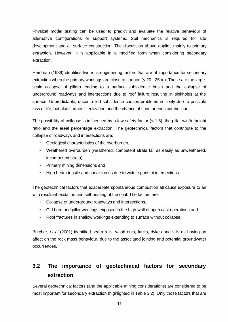
Physical model testing can be used to predict and evaluate the relative behaviour of
alternative configurations or support systems. Soil mechanics is required for site
development and all surface construction. The discussion above applies mainly to primary
extraction. However, it is applicable in a modified form when considering secondary
extraction.
Hardman (1989) identifies two rock-engineering factors that are of importance for secondary
extraction when the primary workings are close to surface (< 20 - 25 m). These are the large-
scale collapse of pillars leading to a surface subsidence basin and the collapse of
underground roadways and intersections due to roof failure resulting in sinkholes at the
surface. Unpredictable, uncontrolled subsidence causes problems not only due to possible
loss of life, but also surface sterilization and the chance of spontaneous combustion.
The possibility of collapse is influenced by a low safety factor (< 1.6), the pillar width: height
ratio and the areal percentage extraction. The geotechnical factors that contribute to the
collapse of roadways and intersections are:
• Geological characteristics of the overburden,
• Weathered overburden (weathered, competent strata fail as easily as unweathered,
incompetent strata),
• Primary mining dimensions and
• High beam tensile and shear forces due to wider spans at intersections.
The geotechnical factors that exacerbate spontaneous combustion all cause exposure to air
with resultant oxidation and self-heating of the coal. The factors are:
• Collapse of underground roadways and intersections,
• Old bord and pillar workings exposed in the high-wall of open cast operations and
• Roof fractures in shallow workings extending to surface without collapse.
Butcher, et al (2001) identified seam rolls, wash outs, faults, dykes and sills as having an
affect on the rock mass behaviour, due to the associated jointing and potential groundwater
occurrences.
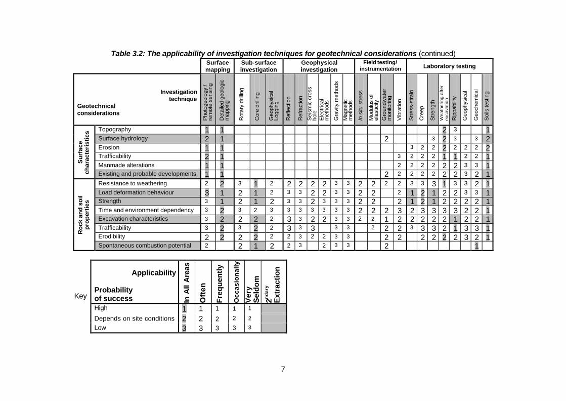
3.2 The importance of geotechnical factors for secondary
extraction
Several geotechnical factors (and the applicable mining considerations) are considered to be
most important for secondary extraction (highlighted in Table 3.2). Only those factors that are

12
ranked applicable in all areas with either a high success probability or a success rate
dependent on site conditions are included (note also that the category for Surface Facilities
has been ignored). This ranking indicates that geotechnical investigations are potentially of
greater significance in underground mining scenarios, with their major contribution being in
understanding the local geological conditions. The most important (i.e. with the most frequent
highest ranking) geotechnical factors overall for both underground and open cast mining are:
• Stratigraphy and lithology,
• Structure,
• In situ stress and
• The effects of fractures on groundwater conditions.
Several investigation techniques could be useful in determining a variety of geotechnical
factors, again specifically for secondary extraction (highlighted in Table 3.3). An analysis of
this table shows that core drilling is the most useful technique of all, resulting in information
for stratigraphy and lithology, structure, the presence of aquifers, the effects of fractures on
groundwater conditions, load deformation behaviour, rock strength, excavation
characteristics and the potential for spontaneous combustion. Depending on site conditions,
geophysical logging appears to be the second most useful technique. This is mainly related
to stratigraphy and lithology, structure and the presence of aquifers. However, detailed
geological mapping, laboratory testing of soils, groundwater monitoring and stress-strain
laboratory tests all have significance. Only two techniques have a high probability of success
in all areas for assessing the potential for spontaneous combustion - core drilling as
mentioned previously and geomechanical testing. In situ stresses are only measurable by
field and laboratory testing. Laboratory testing of soils is only applicable for open cast mining,
except around surface infrastructure for underground mines. The most important
investigative techniques determining geotechnical factors in all areas (i.e. with the most
frequent highest ranking) are:
• Core drilling,
• Laboratory soil testing,
• Detailed geological mapping,
• Laboratory stress-stain measurements and
• Groundwater monitoring.
Ellison and Thurman (1976) address the issue of geotechnical factors in a generalised form,
while Fettweis (1979) deals with the specific geological factors that have geotechnical
implications. Although Dunrud (1998) refers to conditions and tests that are required for
primary underground extraction, these remain applicable for secondary extraction, in
particular with regard to the various effects of primary extraction stresses. These stresses

13
are also controlled and expressed by irregular mining layouts and pillar sizes, partial pillar
extraction, rock bursts and bumps.
Few previous studies have concentrated on critical geotechnical factors of the Witbank
Coalfield and their impact on mining and safety aspects. A study of this nature was therefore
overdue. Ten classes of critical geotechnical factors relevant for secondary extraction have
been identified as a result of this literature study (Table 3.6). These classes are related to
their impact on secondary underground and open cast extraction with regard to rock mass
behaviour (roof caving characteristics, rock burst potential, rib and pillar stability, floor heave,
roof/surface subsidence, slope stability, high wall stability), roof support (mine- and panel-
scale roof support), and explosions / ignitions (gas conditions, spontaneous combustion). A
greater variety of geotechnical factors, and a more pronounced impact thereof, are
suggested for underground operations, when compared with open cast mining. In addition,
the classes are related according to their impact on extraction and hence safety (Table 3.7,
synthesised from various sources). Inspection of Table 3.7 reveals that the largest variety of
classes influence rock mass behaviour and roof support. Fewer classes impact on
explosions and ignitions.
Table 3.6: Classes of geotechnical factors for secondary coal extraction
ClassNumber Class description Required parameters
1 Stratigraphy Length, width, height, depth, dip (if > 50), dip direction2 Rock / coal engineering
propertiesStrength, deformation characteristics, slake durability
3 Spontaneous combustion Location, extent4 Discontinuities Mining-induced or geological, orientation, spacing,
frequency, fill5 Igneous intrusions Geometry, frequency6 Collapse of previous workings Location, extent7 Hydrology Aquifers, effects of fractures8 Stress environment* Horizontal: vertical strain, directions of σ1 and σ3
9 Primary mining parameters Initial mining method, layout, direction10 Secondary mining parameters New mining method, layout, direction
* Composite stress pattern after primary extraction

14
Table 3.7: Classes and their impact on mining
(Classes have different levels of impact, depending on whether underground or open cast miningmethods are to be used during secondary extraction.)
Underground extraction Open cast extraction
Rock mass behaviour Roofsupport
Explosions/
ignitions
Rock massbehaviour
Explosions/
ignitions
Cla
ss n
um
ber
Class descriptionC
ateg
ory
Imp
act
Roo
f cav
ing
pote
ntia
l
Ro
ck b
urs
tpo
tent
ial
Rib
an
d p
illa
rst
abili
ty
Flo
or h
eave
s
Ro
of /
su
rfa
cesu
bsi
de
nce
Min
e-s
cale
ro
of
sup
po
rt
Pan
el-s
cale
roo
fsu
pp
ort
Gas
con
ditio
ns
Spo
ntan
eous
com
bust
ion
Slo
pe
sta
bili
ty
Flo
or h
eave
Hig
h w
all
sta
bili
ty
Gas
con
ditio
ns
Spo
ntan
eous
com
bust
ion
1 Stratigraphy F2 Rock / coal engineering
properties F
3 Spontaneouscombustion V
4 Discontinuities F5 Igneous intrusions F6 Collapse of previous
workings V
7 Hydrology V8 Stress environment F / V9 Primary mining
parameters F
10 Secondary miningparameters V
Shaded blocks indicate areas of impact; F = fixed (uncontrollable during mining); V = variable(controllable during mining)
4. Site visits
A limited number of collieries currently practise secondary extraction in the Northern
Witbank-Highveld Coalfield. Geological and mining conditions also vary considerably
between these sites. This scarcity and variability of the data must constantly be borne in
mind. The following collieries were visited: Kleinkopje, Kromdraai, Arthur Taylor,
Koornfontein and the Boschmanskrans Pillar Project of Douglas Colliery. In addition, the
mine managers of Douglas and Delmas Collieries were also interviewed due to their
extensive experience with stooping.
5. Identification and quantification of the factors
Mining house representatives (geologists, mining engineers and rock engineers) identified
the factors (Table 5.1). The factors were then quantified with a view to selecting the most
suitable mining method, and for open cast and underground operations as a result of the site
visits. The factors are further subdivided into major, moderate and minor considering their
degree of impact when selecting the most appropriate mining method or during actual
secondary mining operations (Table 5.2). Factors ranked 7.0 and above are considered to

15
have major impact; factors ranked between 5.0 and 6.9 moderate impact, while factors
ranking less than 5.0 are considered to have minor impact. The impact on the mining
method, open cast and underground extraction is shown in Figures 5.1 - 5.3, respectively.
Figure 5.1: Quantification of the impact on selecting a mining method
0
1
2
3
4
5
6
7
8
9
10
A1
A2
A4
A5
A6
A8
A9
aA
9b
A1
0A
11
A1
2A
13
B1
B2
B3
B4
B5
B6
B7
C2
C4a
C4b
C6a
C6b C7
C9a
C9b
C10
C11
C13
C16
C17
C18
C19
C20
C21
C22
C23
C24
C25
C26
C27
C28
10 = high negative impact; 0 = no negative impact
Figure 5.2: Quantification of the impact on open cast extraction
0
1
2
3
4
5
6
7
8
9
10
A1
A2
A4
A5
A6
A8
A9
a
A9
b
A1
0
A1
1
A1
2
A1
3
B1
B2
B3
B4
B5
B6
B7
C2
C4a
C4b
C6a
C6b C7
C9a
C9b
C10
C11
C13
C16
C24
C25
C26
C27
C28
10 = high negative impact; 0 = no negative impact

16
Figure 5.3: Quantification of the impact on underground extraction
10 = high negative impact; 0 = no negative impact
0
1
2
3
4
5
6
7
8
9
A1
A2
A3
A4
A5
A6
A7
A8
A9
aA
9b
A1
0A
11
A1
2A
13
A1
4A
15
B1
B2
B3
B4
B5
B6
B7
C1
C2
C3
C4a
C4b C5
C6a
C6b C7
C8
C9a
C9b
C10
C11
C12
C13
C14
C15
C16
C17
C18
C19
C20
C21
C22
C23
C24
C25
C26
C27
C28

17
Table 5.1: Geotechnical factors impacting on secondary extraction
EffectClass Code Factors Geology/rock mass
behaviourMine planning Production
Sub-category
A1 Depth below surface Stress regime, pillar size, support Mining method and layout, panel, bordand pillar dimensions, percentageextraction
F1
A2 Overburden (thickness and lithology) Stress regime, roof stability Mining method Support, machinery F1A3 Extractable thickness Stress regime Mining method and layout Machinery, time effect F1A4 Interburden (thickness and lithology) Roof stability Reserve sterilization, mining method Support F1A5 Seam orientation (dip, strike) Effect of σH Mining method, support patterns Productivity, support F1A6 Inseam partings and channelling
(thickness and lithology)Floor/roof undulations, roof andsidewall stability, gas outbursts*
Extraction method Dilution, machinery F1
A7 Palaeotopographic variations Seam undulations Extraction method Machinery, reserve losses (coal leftin floor / roof)
F1
A8 Roof discontinuities and bed forms Roof stability Support pattern Support F1A14 Remaining reserves (size and geometry) Economic viability F1A15 Coal quality variation (vertical and lateral) Reserve sterilization, mining method Machinery, coal processing F1/V1
1Stratigraphy
B3 Differential compaction Thickness variations, roof falls Machinery F1A13 Coal strength Pillar strength, pillar / roof stability Mining layout, support pattern Support F1
A9a Roof competency Pillar behaviour, roof stability Support pattern Machinery, contamination F1
2Rock/coal
EngineeringProperties A9b Floor competency Floor heave, pillar punching Support pattern Machinery, contamination F1
A10 Methane Explosions Ventilation LOP†, ventilation (underground) V1A11 Spontaneous combustion: Geology and
coal componentCoal degradation (quality andstrength)
Reserve sterilization Reserve sterilization (underground),yield reduction (open cast), LOP†
F13SpontaneousCombustion C28 Spontaneous combustion: Mining
componentCoal degradation (quality andstrength)
Reserve sterilization Reserve sterilization (underground),yield reduction (open cast), LOP†
V3
B4 Faults Seam displacement, rock massbehaviour, pillar strength, roofstability, gas outbursts*
Mining layout, direction of pillar splitting,sequence of pillar extraction, overallmining direction
LOP†, overall mining direction,sequence of pillar extraction,direction of pillar splitting, support
F1
4Discontinuities B5 Joints Rock mass behaviour, pillar strength,
roof stability, gas outbursts*Mining layout Mining direction F1
B1 Dykes Devolatilization, seam displacement,rock mass behaviour, gas outbursts*
Reserve sterilization, mining method andlayout
Reserve accessibility, LOP†, support F15Igneous
IntrusionsB2 Sills Devolatilization, seam displacement,
rock mass behaviour, gas outbursts*Reserve sterilization, mining method andlayout
Reserve accessibility, LOP†, support F1

18
Table 5.1: Geotechnical factors impacting on secondary extraction (continued)
EffectClass Code Factors
Geology/rock mass behaviour Mine planning ProductionSub-
categoryB6 Sinkholes Promotes spontaneous combustion Reserve sterilization Rehandling, safety (men and
machines)V16
Collapse ofworkings
B7 Surface subsidence (general) Rock mass behaviour, promotesspontaneous combustion
Reserve sterilization, mining method Safety (men and machines) V1
A12 Aquifers Stability Reserve sterilization Flooding, reserve sterilization, LOP†,AMD‡ (pumping, treating)
V1
C11 Standing water bodies AMD‡, spontaneous combustion Reserve sterilization Flooding, reserve sterilization, LOP†,AMD‡ (pumping, treating)
V27Hydrology
C26 Seepage water Stability Pumping, LOP†, support V3
C9a Primary mining-induced discontinuitiesand stresses (including macro-fracturing)
Stress regime Mining layout Support F2
C9b Secondary mining-induced discontinuitiesand stresses (including macro-fracturing)
Stress regime Mining layout Support F3
C10 Slope stability (open cast) High wall failure Reserve sterilization V2
8Stress
environment
C25 Horizontal stress Stress regime Mining direction and layout, support Support F3
C7 Pillar condition Poor condition reduces primarysafety factor
Support Support, LOP†, reserve sterilization F2
C8 Previous access May restrict planned access F2
C2 Primary mining method and equipment Stress regime, roof / pillar condition New pillar size/orientation Mining direction, percentageextraction, machinery
F2
C3 Mining history Mining method and layout, overall miningdirection, economic viability
F2
C12 Adjacent panels (extracted or not) Stress regime, overall miningdirection
Mining layout, sequence of pillar extraction Extraction sequence, accessibility F2
C13 Time since primary extraction Pillar decay, thus roof stability,sinkholes, surface stability
Support, reserve sterilization Support, reserve sterilization, LOP† F2
C16 Panel width Stress regime, pillar load, surfacestability, caving mechanism
Support Support F2
C17 New pillar width Stress regime Safety factor Support, loading, production F2
C18 New bord width Stress regime Safety factor, support pattern Support F2
C14 Previous backfilling Stress regime Extraction time (productivity) Dilution F2
C27 Coal ply in roof May prevent roof falls in incompetentroof areas, dilution
Mining method, support Support V2
C4a Primary safety factor Mining method, support, machinery Extractability, support, machinery F2
9Primary mining
parameters
C6a Primary mining height Stress regime, stiffness of pillars,safety factor
Mining method Machinery, increased cutting time F2

19
Table 5.1: Geotechnical factors impacting on secondary extraction (continued)
EffectClass Code Factors Geology / rock mass
behaviourMine planning Production
Sub-category
C15 Overall mining direction Stress regime Mining layout, sequence of pillar extraction Sequence of pillar extraction V3C19 Sequence of pillar extraction Stress regime Mining direction, support Support V3C20 Direction of pillar splitting Stress regime Support Support V3C21 Sequence of fender extraction Stress regime Support Support V3C22 Snook size Stress regime Support Support, time of extraction V3C23 Caving mechanism Stress regime Support pattern Support V3C24 Extraction technique Surface stability Full / partial extraction, reserve sterilization Support V3C5 Multi-seam extraction Stress regime Mining method and layout, pillar
superimposition, sequence of seam extractionSequence of seam and pillarextraction
V3
C1 Surface infrastructure Reserve sterilization V3C4b Secondary safety factor (before mining) Mining method, support, machinery Extractability, support, machinery F3
10Secondary
miningparameters
C6b Secondary mining height (before mining) Stress regime, stiffness of pillars,safety factor
Mining method Machinery, increased cutting time F3
* Due to coal fracturing† Loss of production‡ Acid mine drainage

20
Table 5.2: Factors with major impact
Factors with major impact Class Quantification
Remaining reserves (size and geometry) 1 10.0Surface infrastructure 10 10.0Time since primary extraction 9 9.5Overburden (thickness and lithology) 1 8.3Depth below surface 1 8.0Extractable thickness 1 8.0Primary mining method and equipment 9 8.0Mining history 9 8.0Multi-seam extraction 10 7.5Adjacent panels 9 7.5Primary safety factor 9 7.3Coal strength 2 7.0Dykes 5 7.0
Min
ing
met
ho
d s
elec
tio
n
Sills 5 7.0Spontaneous combustion: Geology and coal component 3 9.0Standing water bodies 7 9.0Spontaneous combustion: Mining component 3 8.0Coal quality variation (vertical and lateral) 1 7.3
Op
en c
ast
extr
acti
on
Remaining reserves (size and geometry) 1 7.0Sequence of pillar extraction 10 8.0Roof competency 2 7.7Caving mechanism 10 7.7Multi-seam extraction 10 7.5
Secondary safety factor (before mining) 10 7.3Sequence of fender extraction 10 7.2Surface infrastructure 10 5.7 – 7.1
Un
der
gro
un
dex
trac
tio
n
Pillar condition 9 7.0
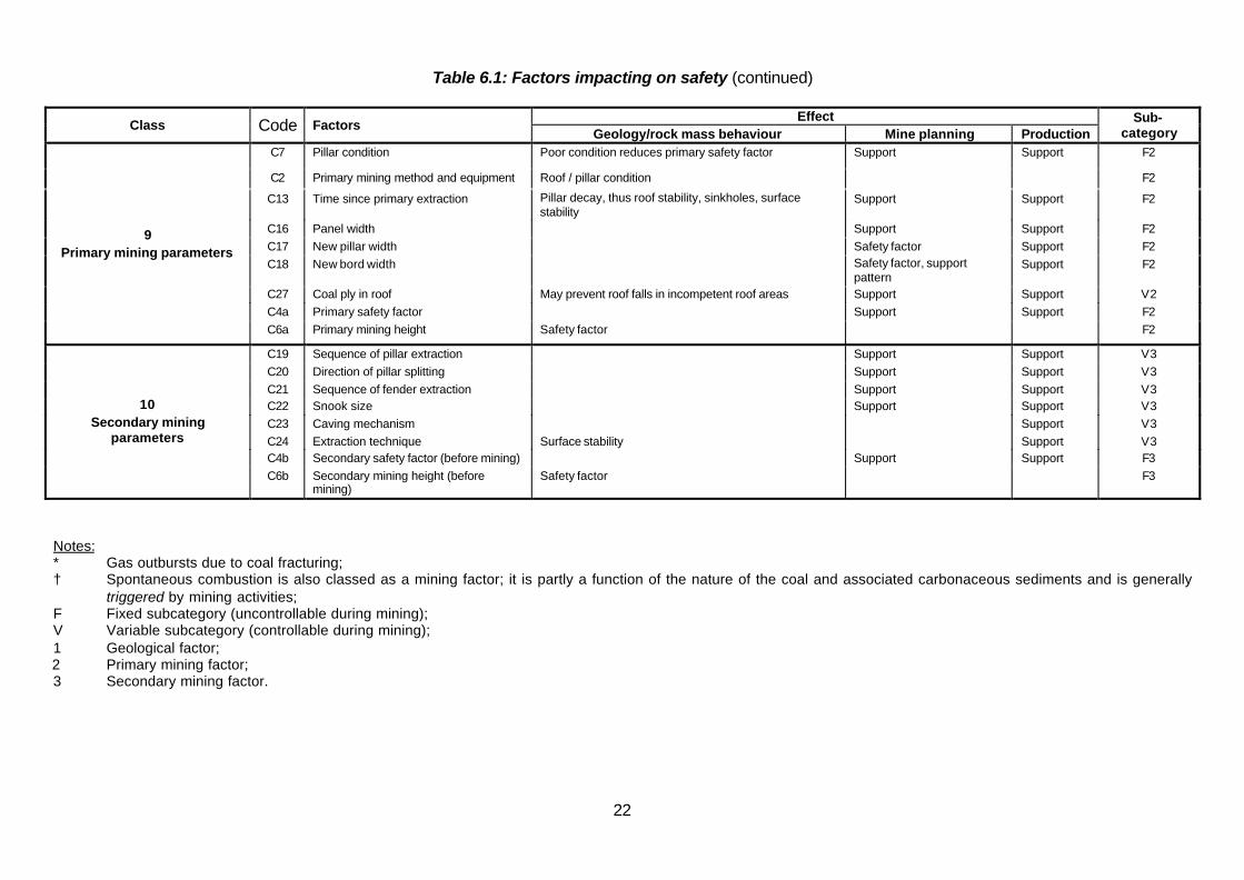
6. Impact of geotechnical factors on safety
The factors identified during site visits as having impact on various aspects of safety are
detailed in Tables 6.1 – 6.5. The factors were also classified into sub-categories according to
whether the factor is controllable or not during mining (i.e. variable or fixed) and to their origin
(geology, primary extraction or secondary extraction).

21
Table 6.1: Factors impacting on safety
EffectClass Code Factors Geology/rock mass
behaviourMine
planningProduction
Sub-category
A1 Depth below surface Support F1A2 Overburden (thickness and lithology) Roof stability Support F1
A4 Interburden (thickness and lithology) Roof stability Support F1
A5 Seam orientation (dip, strike) Support F1A6 Inseam partings and channelling (thickness and lithology) Gas outbursts* F1
A8 Roof discontinuities and bed forms Roof stability Support F1
1Stratigraphy
B3 Differential compaction Roof falls F1
A13 Coal strength Pillar strength, pillar / roofstability
Support F1
A9a Roof competency Pillar behaviour, roofstability
F1
2Rock/coal
EngineeringProperties A9b Floor competency Pillar punching F1
A10 Methane Explosions and fire Ventilation
A11 Spontaneous combustion: Geology and coal component3
SpontaneousCombustion C28 Spontaneous combustion: Mining component
Fire
Ventilation (underground); firecontrol; loss of life; injury
V1
B4 Faults4Discontinuities B5 Joints
Pillar strength, roofstability, gas outbursts*
Support F1
B1 Dykes5Igneous
Intrusions B2 Sills
Gas outbursts* Support F1
B6 Sinkholes6Collapse of workings B7 Surface subsidence (general)
Promote spontaneouscombustion
Safety (men and machines) V1
A12 Aquifers Stability V1
C11 Standing water bodies Spontaneous combustion
Flooding
V27Hydrology
C26 Seepage water Stability Support V3
C9a Primary mining-induced discontinuities and stresses (including macro-fracturing) Support F2
C9b Secondary mining-induced discontinuities and stresses (including macro-fracturing) Support F3
C10 Slope stability (open cast) High wall failure V2
8Stress environment
C25 Horizontal stress Support Support F3
22
Table 6.1: Factors impacting on safety (continued)
EffectClass Code Factors
Geology/rock mass behaviour Mine planning ProductionSub-
categoryC7 Pillar condition Poor condition reduces primary safety factor Support Support F2
C2 Primary mining method and equipment Roof / pillar condition F2
C13 Time since primary extraction Pillar decay, thus roof stability, sinkholes, surfacestability
Support Support F2
C16 Panel width Support Support F2
C17 New pillar width Safety factor Support F2
C18 New bord width Safety factor, supportpattern
Support F2
C27 Coal ply in roof May prevent roof falls in incompetent roof areas Support Support V2
C4a Primary safety factor Support Support F2
9Primary mining parameters
C6a Primary mining height Safety factor F2
C19 Sequence of pillar extraction Support Support V3
C20 Direction of pillar splitting Support Support V3
C21 Sequence of fender extraction Support Support V3C22 Snook size Support Support V3
C23 Caving mechanism Support V3
C24 Extraction technique Surface stability Support V3C4b Secondary safety factor (before mining) Support Support F3
10Secondary mining
parameters
C6b Secondary mining height (beforemining)
Safety factor F3
Notes:* Gas outbursts due to coal fracturing;† Spontaneous combustion is also classed as a mining factor; it is partly a function of the nature of the coal and associated carbonaceous sediments and is generally
triggered by mining activities;F Fixed subcategory (uncontrollable during mining);V Variable subcategory (controllable during mining);1 Geological factor;2 Primary mining factor;3 Secondary mining factor.
23
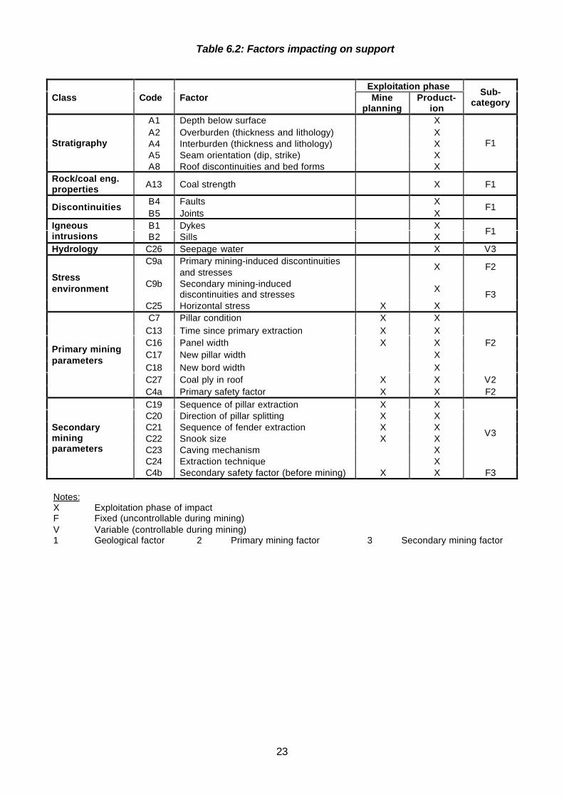
Table 6.2: Factors impacting on support
Exploitation phaseClass Code Factor Mine
planningProduct-
ion
Sub-category
A1 Depth below surface XA2 Overburden (thickness and lithology) XA4 Interburden (thickness and lithology) XA5 Seam orientation (dip, strike) X
Stratigraphy
A8 Roof discontinuities and bed forms X
F1
Rock/coal eng.properties A13 Coal strength X F1
B4 Faults XDiscontinuities
B5 Joints XF1
B1 Dykes XIgneousintrusions B2 Sills X
F1
Hydrology C26 Seepage water X V3C9a Primary mining-induced discontinuities
and stressesX F2
C9b Secondary mining-induceddiscontinuities and stresses
XStressenvironment
C25 Horizontal stress X XF3
C7 Pillar condition X XC13 Time since primary extraction X XC16 Panel width X XC17 New pillar width XC18 New bord width X
F2
C27 Coal ply in roof X X V2
Primary miningparameters
C4a Primary safety factor X X F2C19 Sequence of pillar extraction X XC20 Direction of pillar splitting X XC21 Sequence of fender extraction X XC22 Snook size X XC23 Caving mechanism XC24 Extraction technique X
V3Secondaryminingparameters
C4b Secondary safety factor (before mining) X X F3
Notes:X Exploitation phase of impactF Fixed (uncontrollable during mining)V Variable (controllable during mining)1 Geological factor 2 Primary mining factor 3 Secondary mining factor

24
Table 6.3: Factors impacting on spontaneous combustion/gas/explosions
ExploitationphaseClass Code Factors Type
Production
Sub-category
StratigraphyA6 Inseam partings and
channellingGasoutbursts* X F1
A10 Methane Explosions X V1A11 Geology and coal
componentX F1Spontaneous
combustion †C28 Mining component
FireX V3
B4 Faults XDiscontinuities
B5 JointsGasoutbursts* X
F1
B1 Dykes XIgneousintrusions B2 Sills
Gasoutbursts* X
F1
B6 Sinkholes XCollapse ofworkings B7 Surface subsidence
(general)
Promotespontaneouscombustion
X V1
Hydrology C11 Standing water bodies Spontaneouscombustion
X V2
Table 6.4: Effect of factors impacting on stability
Exploitation phaseClass Code Factors
Type ofstability Mine
planningProduct-
ion
Sub-category
A2 Overburden XA4 Interburden XA8 Roof discontinuities X
Stratigraphy
B3 Differential compaction
Roof
X
F1
A13 Coal strength Pillar/roof X XRock/coal eng.properties A9a Roof competency Roof X X
F1
B4 Faults X XDiscontinuities
B5 JointsRoof
X XF1
Collapse ofworkings B7 Surface subsidence Surface X X V1
A12 Aquifers X X V1Hydrology
C26 Seepage waterRoof
X V3Stressenvironment C10 Slope stability High wall X X V2
C7 Pillar condition Pillar/roof X X
C13Time since primaryextraction
Roof/surface X X
F2Primary miningparameters
C27 Coal ply in roof Roof X V2Secondaryminingparameters
C24 Extraction technique Surface X X V3
Notes for both tables:* Gas outbursts due to coal fracturing† Spontaneous combustion is also classed as a mining factor; it is partly a function of the nature of the coal
and associated carbonaceous sediments and is generally triggered by mining activitiesX Exploitation phase of impactF Fixed (uncontrollable during mining)V Variable (controllable during mining)1 Geological factor 2 Primary mining factor 3 Secondary mining factor

25
Table 6.5: Factors impacting on other safety aspects
Exploitation phaseClass Code Factors Type Mine
planningProduct-
ion
Sub-category
A13 Coal strength Pillarstrength
XRock/coalengineeringproperties A9b Floor competency
Pillarpunching
XF1
B4 Faults X XDiscontinuities
B5 JointsPillarstrength X X
F1
A12 Aquifers X X V1Hydrology
C11 Standing waterbodies
FloodingX X V2
C2Primary miningmethod andequipment
Roof/pillarcondition
X X
C17 New pillar width X X
C18 New bord width X X
Primary miningparameters
C6aPrimary miningheight
Safetyfactor
X X
F2
Secondaryminingparameters
C6bSecondary miningheight (beforemining)
Safetyfactor
X X F3
Notes:X Exploitation phase of impactF Fixed (uncontrollable during mining)V Variable (controllable during mining)1 Geological factor 2 Primary mining factor 3 Secondary mining factor
7. Impact of geotechnical factors on resource/reserve classification
The impact on the resource / reserve classification, for both opencast and underground operations, was
established (Table 7.1). Factors that will prevent the upgrading of a resource to a reserve impact on the
economic viability of the deposit, the sterilization of the resource and the accessibility of the resource. Other
factors that may prevent the upgrading of the resource to reserve status affect coal losses during extraction:
dilution, contamination, coal left in the roof or floor and yield reduction through quality degradation by
spontaneous combustion.

26
Table 7.1: Factors impacting on the resource/reserve classification
Potentialimpact
Dependantvariable Factors Code
Remaining reserves (size and geometry) A14Economic viability
Mining history C3
Interburden (thickness and lithology) A4
Coal quality variation (vertical and lateral) A15
Spontaneous combustion:Geology and coal component
A11
Mining component C28Dykes B1Sills B2Sinkholes B6Surface subsidence (general) B7Aquifers A12Standing water bodies C11Slope stability (open cast) C10Pillar condition C7Time since primary extraction C13Extraction technique C24
Reserve sterilization
Surface infrastructure C1
Dykes B1Sills B2
Will preventupgrading aresource to areserve
Reserveaccessibility
Adjacent panels (extracted or not) C12Inseam partings and channelling A6Previous backfilling C14DilutionCoal ply in roof C27
Coal left in floor/roof
Palaeotopographic variations A7
Roof competency A9aContamination
Floor competency A9b
Geology and coal component A11
May preventupgrading aresource to areserve, ifunforeseenconditionsencountered Yield reduction
(spontaneouscombustion) Mining component C28
8. Findings
The factors impacting on safety, mining method selection, the mining operation (open cast or underground)
and on the resource / reserve classification are shown in Table 8.1.
In summary, those factors that are critical for safety reasons are also important with regard to the financial
feasibility of any secondary coal extraction operation. Geotechnical factors affecting safety can have major
monetary implications, potentially far beyond that of any actions required to prevent the risk and / or restore the
mining environment after a safety-related incident has occurred.

27
Table 8.1: Common factors
Factor Classificationimpact
Standing water bodies Reservesterilization
Spontaneous combustion: Geology andcoal component
Reservesterilization andyield reduction
Open castoperations
Spontaneous combustion: Miningcomponent
Economic viability
Roof competency ContaminationUnderground
operationsPillar condition
Reservesterilization
Dykes
Sills
Reserveaccessibility andsterilization
Time since primary extraction
Miningmethod
selectionSpontaneous combustion: Miningcomponent
Reservesterilization
9. Application
As each secondary extraction site is unique, it is not possible to identify a list of factors that
will be significant at every site. However, this report can serve to sensitise personnel to which
factors are most likely to be important. The information contained herein, particularly the
tables, can then be used as a guide to investigate further.
It is suggested that particular attention be paid to those areas of Tables 3.1 and 3.2 that are
highlighted (indicating applicability to secondary extraction) with a number 1 in the largest
font. These are the aspects of critical importance to secondary extraction. Table 5.1 can be
used to familiarise the user with the potential effects a factor may have, and in which area
those effects may manifest themselves. This will provide forewarning of what to expect if a
particular factor is present. Table 5.2 shows those factors that should be considered at every
site, as they are those most likely to have impact in the majority of sites. Table 6.1 is similar
to Table 5.1, except that it deals with the effects on safety only. It is important that these
effects should be well understood before exploitation occurs. Tables 6.2 – 6.5 simply provide
further detail on the factors in Table 6.1. The presence or absence of the factors identified in
the tables should be ascertained, and their possible impact assessed, before extraction
occurs.

28
Figures 9.1 – 9.3 show the potential impact geotechnical factors may have when selecting a
suitable mining method, or during open cast or underground secondary extraction. The
diagrams have been colour-coded to indicate those factors that have specific impact on the
safety of the operation. These can be referred to when considering secondary extraction.
It must be stressed that this report does not provide a methodology to be applied in every
case of secondary extraction. As each site is unique, the most that can be done is to educate
individuals as to what effect a factor can have in order to allow timeous identification of
important factors and provide suggestions as which factors are most likely to be critical.

29
Notfeasible
Notpossible
Impediment tofurther extraction
Mustprotect
No / insufficient reserves
Long and/or stratacondition poor
Not necessary to protect
Remaining reserves Mine with adjacent reserves
Depth below surface
Surface infrastructure Extraction technique :Partial extraction; barrier pillars
Short and/or strata condition good
Consider additional support /mining techniques / machinery
Time since primary extraction
Overburden lithology
Underground secondaryextraction
Extractable thickness
Adjacent panels (extracted or not)
Primary safety factor
Coal strength
Sills / Dykes
Open cast secondaryextraction
Stripping ratios
Primary safety factor
Coal strength
Sills / Dykes
DO NOT MINE
Consider overallmining direction
Primary mining method andequipment; mining history
Investigate variousmining techniques
< ± 80 m
Overburden lithology
± 80 - 400 m
Sufficient
Insufficient
Minor dolerite
Insufficient
Depth > ± 400 m
Additionalsupport
Incompetent
Impediment to furtherextraction
Not feasible
Primary mining method andequipment; mining history
Yes
NoNot feasible
Minor / simple
Adequate
Adequate
Complex -isolated, small reserve blocks
Minor / simple
Consider multi-seam extraction
Too high
Major dolerite
Consider multi-seam extraction
Not feasible
Adequate
Adequate
No impediment tofurther extraction
No impediment tofurther extraction
Sufficient reserves
Suitable
Feasible
Possible
Sufficient
Competent
Feasible
Too lowToo low
Too weakToo weak
Complex -isolated, smallreserve blocks
Feasible
FeasibleN
ot f
easi
ble
Feasible
Not feasible
Feasible
Key:Fill = Rock mass behaviour
Border = Production
Stability
Support
GasRoof/ pillarcondition
Figure 9.1: Potential impact on mining method selection

30
Notpossible
Yes -pumping required
Spontaneous combustion –mining component
Standing water bodies
Coal quality variation:vertical and lateral
Remaining reserves
Assess:
Spontaneous combustion –geology and coal component
Geology related aspects: Seam thickness,frequency of faulting, caving characteristics, virgincoal temperature, likelihood of outbursts and thepresence of carbonaceous strata or roof.Coal related aspects: Maceral, sulphur and alkalinecontents, rank, porosity (i.e. inherent moisturecontent), friability, fracturing and cleating.
Decrease: broken material heaps, machinery heat, stressdistributions (causing fractures) by improved blasting, ventilation
by sealing old workings completely, the relative humiditydifferential between air and coal, pit length.Increase: machinery available, production rates and ventilationof old workings.Align: pit orientation and strip layout with highwall
MINE DO NOT MINE
Investigate most economic method of separating qualities– in pit by the mining method or at the plant, dependingon available machinery and plant design / capacity.
Pump immediately prior to mining -early pumping can exacerbate theheat of wetting / condensation, actingas trigger for self-heating.
Insufficient
Possible
Possible
Yes Not possible
Not possible
High impactYes
Low impactNo
No
No
No
Sufficient
Yes
Possible
Key:Fill = Rock mass behaviour
Border = Production
Fire
Ventilation Flooding
Figure 9.2: Potential impact on open cast extraction

31
Notsatisfactory
Notpossible
Complex -isolated, small reserve blocks
Exist -breaching possible
Assess for each seam:
DO NOT MINE
Short and/or strata condition good
Sills / Dykes
Extraction technique:Partial extraction; barrier pillars
Extraction technique:Full extraction
Aquifers
Don’t exist OR exist,breaching improbable
Surface infrastructure
Serious impact on surfaceutilisation
MINE
Overall mining direction, pillar extractionsequence, pillar splitting direction, fenderextraction sequence, ideal snook size andcaving mechanism.
Pillar conditions, safety factors,mining height, roof and floorcompetency, roof discontinuities,faults and joints.
Additionalsupport
Single seam extraction
Interburden thickness
Multi-seam extraction
Underlying seams extracted
Seam extraction sequence:individual extraction ORsimultaneous extraction
Overlying seams extracted
To alleviate collapse, the partingthickness, flooded upper workings,remnant pillars and roof supportmust be considered.
Then determine:
Possible
Yes
Must protect
No
Sufficient separation
General surface subsidence
Long and/orstrata condition poor
Additional supportTime since primary extraction
Extensive
Possible
Minor
Minor / simple
Protection unnecessary
Not possible
Yes
FeasibleNot feasible
Unfavourable
Favourable
Unfavourable
No
No
Pillar conditions, safety factors,mining height, roof and floorcompetency, roof discontinuities,faults and joints.
Assess for each seam:
Overall mining direction, pillar extractionsequence, pillar splitting direction, fenderextraction sequence, ideal snook size andcaving mechanism.
Feasible
Notfeasible
Insufficient separation
Yes
To alleviate collapse, the stratathickness, length of unsupportedstrata and stress on upper seampillars must be considered.
Favourable
Then determine:
Satisfactory Satisfactory
Not satisfactory
Additionalsupport
Key:Fill = Rock mass behaviour
Border = Production
Stability
Support
Gas
Flooding
Figure 9.3: Potential impact on underground extraction

32
References
Ellison, R.D. and Thurman, A.G. 1976. Geotechnology: An Integral Part of Mine Planning (In:Coal Exploration. Miller Freeman Publications. 1, p. 324-372.
Hardman, D.R. 1989. The Consequences of Leaving Vast Mined-out Areas Standing onPillars. Proceedings of the Total Utilization of Coal Resources, SAIMM School. Witbank.
Hill, R.W. 1994. Multi-seam design procedures. SIMRAC Final Project Report COL026.
Schweitzer, J.K., Wallmach, T., Grodner, M. and Quaye, G. 1997. Define Geotechnical Areasfor Mining Industry on the Basis of Differing Rock Mass Behaviour. SIMRAC Report GAP416. p. 99.
Butcher, R.J., Walker, D.J., Joughin, W.C., Birtles, A.N. and Terbrugge, P.J. 2001.Methodology for the safe cleaning and making safe of various height (10 – 35m) highwalls.SIMRAC Report GEN703. p. 216.

33
APPENDIX A - Explanatory notes for some of the factors
Class 1: Stratigraphy
Depth below surface (code A1, sub-category F1)
Stooping in South Africa currently operates optimally between 40 and � 250 m below
surface, where the effect of depth on the stooping operation is minimal; at depths outside this
range the impact increases. The maximum depth at which stooping is viable may increase in
the future. Longwalling (a total extraction method) can be economically practised at greater
depths, but this technique is not considered in this investigation.
Overburden thickness and lithology (code A2, sub-category F1)
The competency of the immediate overburden is important. Thick, massive sandstones or
moderate to thick dolerite sills are usually competent, while silt- or mudstones, cross-bedded
sandstones, and sandstones inter-bedded with silt- and/or mudstones are generally
incompetent. Providing the overlying strata are competent, the impact is quantified as 5
(moderate).
Extractable thickness (code A3, sub-category F1)
The total thickness of coal that can be extracted impacts on the stripping ratios and thus
becomes an economic factor. The currently accepted South African minimum extractable
thickness is ~ 1.2 m. However, thinner seams are extracted in other parts of the world,
notably Europe. Stooping is most suitable where the seam thickness is 1.2 - 4 m (using
continuous miners), but is also dependent on the equipment available. The impact is
quantified as 2 (minor) in the optimal thickness range. Where seams are thicker, primary
extraction of a select horizon could be by longwall extraction, or by top or bottom coaling,
leaving pillars that could then be extracted by stooping.
Interburden thickness and lithology (code A4, sub-category F1)
Assuming that multi-seam extraction has been practised during the primary mining, an
interburden thickness of 0 - 15 m has major impact on stooping (impact = 9); in this case,
pillars of overlying seams must be superimposed to assure stability of the strata. Thickness
greater than 15 m poses little problem and is quantified as 1 (minor). If the interburden
between two potentially extractable seams is very thin (< � 1 m), the strength of the parting
between them becomes critical. This impacts on the method of extraction of the seams, the

34
equipment used and the blasting techniques employed, both for an open cast operation and
for stooping.
Seam orientation (code A5, sub-category F1)
Dips in most South African coalfields (excluding the Soutpansberg field) are generally low. In
such cases, the impact is minor. However, if dips exceed � 3�, stooping is excluded and the
impact of the seam orientation rises to major (10).
Thickness and lithology of in-seam partings and channelling (code A6, sub-category F1)
The thickness and strength of in-seam partings controls their extractability. Partings with
strengths ~ 90 MPa cannot be extracted owing to machinery constraints; thick partings can
likewise not be extracted. A continuum from thin, strong partings to thick, weak partings has
major impact on the extractability (8 and greater), while thin, weak partings have minor
impact. Thick, weak partings also increase contamination.
Palaeotopographic variations (code A7, sub-category F1)
When present and of significant amplitude and frequency, the impact of variations in the
palaeotopography is high (7 - 8), particularly when present in the floor. These undulations
impact on the machinery suitable for extraction, as well as the rate of extraction. Production
delays may result in premature goafing, endangering lives, machinery and productivity.
Roof discontinuities and bed forms (code A8, sub-category F1)
In general the impact is moderate (5 - 6), but is dependant on correct support during both
primary and secondary extraction to provide effective management of roof conditions. Roof
bolt installation once support problems have been encountered is not effective, as bed
separation would already have occurred in the overlying strata (Beukes, 1992). The angle at
which the discontinuity, whether major or minor, crosses the bord or roadway is of great
importance. Discontinuities parallel to the length of the bord are more critical and difficult to
support than perpendicular discontinuities. Adequate support is thus decisive in preventing
failure. Pillar failure transfers stresses to the remaining pillars, thus increasing their load and
possibly exceeding their design strength. Further failure and loss of reserves (and possibly
also workers and machinery) may result.
Size and geometry of remaining reserves (code A14, sub-category F1)
The impact of the remaining reserves on the secondary extraction is dependent on the size
of the reserves, together with the equipment available. Where reserves are small and little
equipment is available, the impact is major (10); however, if equipment is available the

35
impact can vary from minor through to major. Large reserves with little available equipment
have similar impact ranges (i.e. 0 - 10), while the impact on large reserves with plentiful
available equipment is minor.
Class 2: Rock / coal engineering properties
Coal strength (code A13, sub-category F1)
Coal strengths affect the time that elapses before pillars crush. If coal strengths are low,
pillars may crush ahead of the stooping operation. This causes the extraction rate to drop,
increasing the extraction time. This may result in premature pillar collapse. Coal strengths
that are either too low or too high have major impact on stooping and both result in
premature failure of the pillars and supported strata. Numerous coal strength tests have been
performed on Witbank and Highveld coals.
Roof competency (code A9a, sub-category F1)
The lithology and discontinuities of the immediate roof rock govern its competency and
hence the support required. Although contamination may occur and machinery may get
stuck, poor roof conditions can generally be managed. Comments made regarding roof
discontinuities and bed forms apply equally here. The impact is considered moderate.
Floor competency (code A9b, sub-category F1)
Poor floor competency tends to have greater negative impact than poor roof competency.
Floor heave, reduced pillar safety factors and pillar punching can result. Floor heave is
attributed to three reasons (Beukes, 1992): high horizontal stresses where the floor fails in
tension, high vertical stresses where pillar punching results and swelling rocks (containing
clay minerals) in the floor strata. Remnant pillars in lower mined seams cause stress
concentrations that will be transferred to the upper seam workings. This may be observed as
pillar spalling or floor heave.
Class 3: Spontaneous combustion
Methane (code A10, sub-category V1)
The impact of methane in underground collieries is extremely high as satisfactory ventilation
of the goaf is almost impossible. Thus build-up of methane can occur until explosive
concentrations are reached, often with tragic results. In open cast secondary extraction
operations the impact of methane is low as it is continuously vented to the atmosphere and
rarely reaches explosive concentrations.

36
Spontaneous combustion (code A11, sub-category F1 and code C28, sub-category V3)
Spontaneous combustion has been divided according to two factors: spontaneous
combustion arising owing to the nature of the geology and the coal itself and spontaneous
combustion due to mining practices. That due to the geology and the coal is fixed, as nothing
can be done to ameliorate it, while that due to mining can be controlled by adapting the
mining practices. Little research appears to have been done by industry on its effect on coal
qualities and yields, resulting in reserve loss. Although significant, it does not appear to
prevent mining. At worst it causes production delays as preventative measures must be
undertaken, additional costs associated with these measures are incurred and logically the
product yields must be reduced. Of the three Anglo Coal open cast secondary extraction
operations (Kleinkopje, Kromdraai and New Vaal), all three are experiencing problems with
spontaneous combustion, although that at Kleinkopje is very recent (October 1999). It would
seem that spontaneous combustion will occur at some stage; a method or technology to
prevent self-ignition long enough to allow mining is required. Ceasing mining operations is
not a solution; the only permanent solution currently known is total extraction. The burning
collieries around Witbank are not only a safety and pollution hazard, but also threaten the
Maputo Development Corridor, as the main rail link to Mozambique passes through the area
and is surrounded by these old, burning collieries. If methane occurs in explosive
concentrations the possibility of ignition reaches dangerous proportions and a colliery may
have to be closed (e.g. Lidell and Blair Atholl collieries in Australia). Fortunately South
African collieries are not particularly gassy. Spontaneous combustion is dealt with in greater
detail in Section 5.3.
Class 4: Discontinuities
Faults (code B4, sub-category F1) and joints (code B5, sub-category F1)
Faults with large throws (order of tens of metres) are largely absent in the Witbank-Highveld
Coalfield. Minor faulting of less than 2 m is found, but has minor impact on the extraction.
Jointing can however, have major impact on both open cast and underground operations.
Ideally pillar sides should not be parallel to joint sets as spalling is more likely to occur. The
direction of advance should be perpendicular to the major joint direction.
Class 5: Igneous intrusions
Dykes (code B1, sub-category F1) and sills (code B2, sub-category F1)
The impact of dykes and sills on the mining operation is low to moderate, depending on the
thickness and frequency of intrusion and the amount of devolatilization present. Thin dykes
have often been found to cause greater devolatilization than thicker dykes. The heat of
intrusion also reduces the coal strength. During stooping operations, the row of pillars

37
containing the dyke is usually not extracted. Sills overlying the seam may have increased the
strength of the roof lithologies due to the baking effect, thus having a positive impact on
extraction. These will determine whether an area can be accessed by open cast methods.
Areas overlain by a sill are usually not accessible by open cast operations, as are areas of
intense dyke intrusion. The low ranking of these features is thus a result of the open cast
operations being in areas of few intrusions. I would suggest that intrusives are extremely
important, probably having a ranking of around 8. There appears to be a connection between
the intensity of intrusion and the presence of methane, more methane being found in areas
of intense intrusion. Methane will assume significance only in areas where it is present in
explosive concentrations or where there is spontaneous combustion. Dykes and sills in
underground operations govern the accessibility of reserves. Loss of reserves may occur as
a result of burning and the development layout may be affected, particularly where the coal
has been displaced by the intrusion. This will lead to production delays and increased
development costs. The rock mass behaviour may be adversely affected and a different
mining method may need to be employed. Reserve sterilisation will occur where reserve
blocks are rendered inaccessible by the intrusions.
Coal strength (class 5, code A13, subcategory F1)
The coal strength influences the strength and condition of pillars, roofs and sidewalls.
Class 6: Collapse of workings
Sinkholes (code B6, sub-category V1)
The size and frequency of sinkholes will have varying impact on the secondary extraction.
Only one site visited had serious subsidence problems (Kromdraai). In areas where
subsidence is extensive, such as the state-owned mines around Witbank (Transvaal and
Delagoa Bay, Middelburg Steam, etc.), the importance of sinkholes and unstable ground will
increase. The unstable ground may cause a change in machinery requirements (e.g. using
draglines rather than trucks and shovels, using special explosives that are less viscous and
can be pumped over longer distances thus keeping explosives vehicles away from
dangerous ground). Different blasting techniques (such as buffer blasting) may be effective in
certain cases to close voids. Any remedial actions required will at the very least result in
production delays, although it is unlikely that mining will be prevented.
Class 7: Hydrology
Aquifers (code A12, sub-category V1)
Breaching of aquifers should be avoided whenever possible, particularly in terms of the
environmental problems associated with these. Minor aquifers have little impact on mining,

38
only requiring additional pumping to reduce volumes. Breaching of major aquifers may cause
flooding of the workings, with possible loss of life and machines, or even flooding of the
entire mine. The impact of such an occurrence is extremely high. Breaching of aquifers may
result in flooding of the mine (or portions thereof), together with depletion of water boreholes.
Although these factors may not cause abandonment, they will have an impact in terms of
remediation costs and delayed production.
Standing water bodies (code C11, sub-category V2)
Small amounts of water will have minimal effect on mining, while large volumes will have
major impact on both open cast and stooping operations. The entire reserve may be lost
owing to sudden, rapid influx of water. At a minimum, production delays and pumping costs
will be incurred. Besides the logistics and cost, dewatering of old bord and pillar panels
allows air ingress to the previously sealed workings. Oxidation will begin, increasing the
likelihood of spontaneous combustion. Acid mine drainage may become a problem, requiring
expensive remediation measures. Dewatering also removes the support the water has lent to
the pillars, which in time may lead to pillar spalling, roof collapse and sinkhole formation. The
water may also act as a lubricant along joints and fractures promoting failure.
Seepage water (code C26, sub-category V3)
Any discontinuity, whether structural (fault planes), depositional (contacts between different
lithologies) or mining induced (fractures), may act as a conduit for seepage water, thus
decreasing the competency of such discontinuities and increasing the chance of catastrophic
failure.
Class 8: Stress environment
Horizontal stress (code C25, sub-category F3)
Stresses are due to the confinement of the rock mass and unloading as a result of erosion.
The effects of horizontal stresses are seen in pillar spalling and failure along poorly
supported discontinuities.
Class 9: Primary mining parameters
Pillar condition (code C7, sub-category F2)
Where pillars have deteriorated with time, the initial safety factor is reduced and the coal
strength factor must be adjusted accordingly. This will only be important where the pillars are
weak; collapse may occur if pillars are required to bear heavy loads. This factor will probably
not operate in isolation, but will be linked with others such as final primary safety factors, the
competency of the roof and floor, any discontinuities within the pillars and the strength of the

39
coal itself. Pillars in coal that has been mined by drill and blast methods tend to be more
fractured and prone to spalling than where mined with continuous miners. Cracking, scaling
and roof-pillar fractures are common. However, with time the condition of the pillars mined
with continuous miners approaches that of the drill and blast pillars (pers. comm., N. van der
Merwe).
New pillar width (code C17, sub-category F2)
Narrow pillars will have major impact on stooping while broader pillars will have moderate
impact.
New bord width (code C18, sub-category F2)
Roof collapse and support problems are likely to be experienced where bord widths are
greater than approximately seven metres.
Coal in the roof (code C27, sub-category V2)
Leaving a thin skin of coal in the roof can help prevent roof falls, thus reducing contamination
of the remaining reserves.
Class 10: Secondary mining parameters
Secondary safety factor (code C4b, sub-category F3)
This needs to be calculated once the appropriate measurements have been taken.
Sequence of fender extraction (code C21, sub-category V3)
The order of extraction should be from the goaf towards the solid.
Multi-seam extraction (code C5, sub-category V3)
The majority of collieries mine more than one seam, which should be taken into
consideration during the design stage. The underground extraction of one seam may affect
the subsequent mining of another seam if the seams are in close proximity. This is due to
subsidence and stress concentrations, which can result in difficult mining conditions The
extraction sequence should be from top seam to bottom seam(s) for strata control purposes.
However, marketing constraints and coal quality variation make it difficult to mine in
descending seam order. In the Witbank area multi-seam bord and pillar mining is common
and several combinations of mining multiple seams have been tried in the Natal coalfields.
The potential safety hazard associated with different multi-seam mining sequences and
extraction methods (Hill, 1994) is shown (Table A1).

40
Table A1: Potential safety hazards in multi-seam mining layouts(after Hill, 1994)
Method of Mining
Upper Seam Lower SeamSafety Hazard
Bord & pillar Bord & pillarSpalling on pillars and parting collapse if the interburden is thinand there is no superimposition.
Pillar extraction (2) Bord & pillar (1) Roof falls in lower seam, parting collapse if interburden is thin.
Bord & pillar (2) High extraction (1)Tensile zones and spalling in upper seam when mining overgoaf/solid boundary, floor collapse over incomplete goafs. Highsafety risk if Parting:height ratio low.
Remnant pillar (1) Bord & pillar (2) Intersection collapse in lower seam when mining underremnant.
Pillar extraction (1) Pillar extraction (1) Simultaneous mining in both seams - roof falls in lower seam.
High extraction (1) High extraction (2) Preferred method of mining except where remnant pillars andwater exist.
Note: Figures in brackets refer to the sequence of seam extraction
The feasibility of multi-seam extraction is also dependent on the nature and thickness of the
interburden, plus whether sufficient reserves remain at suitable depths. For example, the
interburden between two seams may be such that mining of the lower seam is precluded, or
the seam may be of insufficient thickness to warrant exploitation. Like the extractable
thickness, multi-seam extraction impacts on the stripping ratios in open cast operations. It
affects the mining method, mining layout, the superimposition of pillars and the sequence of
seam extraction in underground operations.
Overall mining direction (code C15, sub-category V3)
In horizontally disposed seams, the direction of mining has minor impact on the stooping.
However, in areas where the seams have pronounced dip, the impact is moderate to major.
The direction of stooping should occur away from low-lying areas where water collection can
occur and away from previously mined panels. Wherever possible, mining between two
goafed panels should be avoided; where not possible, extraction should be from the oldest
panel towards the youngest. The extraction direction should be constant in order to distribute
the load evenly to the adjacent unmined pillars. The resultant micro-cracks in the roof and
surrounding pillars will then have the same orientation and pattern as the existent stress
contours. Changing the direction of stooping will change the directions of the stress contours,
leading to the development of a new set of micro-cracks crosscutting the pre-existing ones;
this may cause severe undesirable strata instability.
Surface Infrastructure (code C1, subcategory V2)

41
Surface infrastructure becomes less significant with increasing depth below surface, or if the
overlying strata are sufficiently competent to support the overburden.
Direction of splitting (codeC20, sub-category V3)
Pillars should always be split in the direction of overall mining (into the main goaf), ensuring
that the main pillar fractures develop parallel to the goaf. The fender closest to the goaf will
be weakened by these fractures when a pillar is split parallel to the goaf.
Extraction technique (codeC24, sub-category V3)
Partial high extraction mining, (by partially extracting all pillars or by total extraction of some
pillars, leaving others in situ - chequer board extraction) is sometimes unavoidable in order to
prevent subsidence of the overlying strata. According to Canbulat (2000), the design
principles for partial high extraction methods are complicated. The stiffness of both the pillars
and the overburden strata must be determined. The system stiffness must be greater than
the pillar stiffness for the partial high extraction layouts to be safe (i.e. failure is in a controlled
manner). The pillar width:height ratio falls within the range of non-violent failure at lower
mining heights where the panel width becomes less important; it is therefore more efficient to
employ chequer board pillar extraction. Protecting the overburden beams from failure by
restricting panel widths, predominantly controls partial high extraction at higher mining
heights where it is more efficient to split all pillars while restricting panel width.
Snook size (code C22, sub-category V3)
In pillar extraction, the aim is to remove all pillars completely. However, this is always difficult
to achieve. Snooks or even whole pillars will be left behind. Therefore, the "correct size"
snooks should be left to protect the pillars and control the stresses on the pillars still to be
extracted.

42
APPENDIX B - Description and rationale of the nominal
terms
Category – a set of factors with similar possibility of control during mining. There are twocategories:
• Category F – fixed: the mining operation has no control over these factors, whichdictate the rock mass behaviour.
• Category V – variable: some control is feasible over the variable factors. Thesefactors may modify, rather than dictate, the rock mass behaviour.
Class – a set of factors of common type. The ten classes (1 to 10) are defined in Table 2.2.Factors can belong to the same class, but different groups, e.g. aquifers and standing waterbodies both belong to class 7 (hydrology), but aquifers are part of group A (primarygeological factors) as they are a result of the geology of the deposit, while standing waterbodies are classified as group C (mining factors) because they are controlled by the inflow ofwater into the old workings. Similarly, factors can belong to the same group, but differentclasses. An example of this is the final safety factor from the primary extraction (class 7 –primary mining parameters) and mining induced discontinuities and stresses (class 8 – stressenvironment), which both belong to group C (mining factors) as they are a result of theprevious mining.
Code – a unique identifier for each factor, based on the group into which it falls. Thus groupA factors are labelled A1 through to A14, etc. The numeric part of the code does not implyany hierarchy within the factors.
Dependant variables – the aspects of secondary extraction affected by the factors.
Factor - those characteristics of the coal seam and associated strata that impact on seamextraction, including safety.
Group – a set of factors with similar origin. The groups are:
• Group A: primary geological factors – owing to syn-depositional geological features,• Group B: secondary geological factors - resulting from post-depositional geological
features and• Group C: mining factors – arising from the primary extraction.
Subcategories – categories F and V are divided into two subcategories each:
• Subcategory F1 - those factors present before mining commenced. They are anintrinsic component of the rock mass, and control its behaviour to a very large degree.All primary and secondary geological factors (bar methane, spontaneous combustion,aquifers and sinkholes) belong to this subcategory.
• Subcategory F2 – factors arising from the primary extraction. Since mining hasceased, no changes are possible.
• Subcategory V1 - primary and secondary geological factors to which some remedialmeasures can be applied.
• Subcategory V2 - mining factors that can be controlled during secondary extraction.

CSIR: MINING TECHNOLOGYCUSTOMER ASSESSMENT FORM
AUTHOR TO COMPLETE:PMS PROJECTNUMBER:
Y5958 OE2: 4351 REPORTNUMBER:
2002-0251
CLIENT ORGANIZATION: SIMRACCLIENT NAME:CLIENT POSITIONHELD:CLIENT ADDRESS: Private Bag X 63
Braamfontein2017
TEL NUMBER: (011) 358 9180 FAXNUMBER:
(011) 403 1821
NATURE OF WORK OR SERVICES RENDERED/REPORT TITLE:The impact of geotechnical factors on the secondary extraction of coal in the Witbank and northernHighveld coalfields, specifically related to safety.(Final project report)
MEMBER OF STAFF / AUTHOR OFREPORT:
L. S. Jeffrey
CLIENT TO COMPLETE:PLEASE MARK THE APPROPRIATE NUMBERHAVE WE DELIVERED TO YOU ….. Excellent Average Poor1 On brief (meeting agreed
specifications of the assignment)?7 6 5 4 3 2 1
2 On budget (have we provided valuefor money)?
7 6 5 4 3 2 1
3 On time (deadlines met with anappropriate sense of urgency)?
7 6 5 4 3 2 1
4 Quality (are we meeting the higheststandards)?
7 6 5 4 3 2 1
5 Specific comments/suggestions or complaints (please write on the reverse side if morespace is required):
6 Did this job add value to the relationship of our companies? YES NO7 Would you like me to call you to discuss any of the above in detail? YES NO
SIGNATURE:_______________________________DATE:__________Please return this assessment sheet, by fax if possible, at your earliest convenienceto:DR R G GÜRTUNCA Fax No.: (011) 726-7308Divisional Director Tel No.: (011) 358-0072CSIR: Mining TechnologyP O Box 91230Auckland Park2000