the implementation of nos. 16 and 20 shaft projects · the implementation of nos. 16 and 20 shaft...
TRANSCRIPT

THE IMPLEMENTATION OF NOS. 16 AND 20 SHAFT PROJECTS 267
IntroductionImpala Platinum Ltd approved two new shaft projects at theend of September 2004, Nos. 16 and 20 Shafts. Both shaftprojects are stand-alone entities and are being sunk fromsurface. No 16 Shaft is located in the south-east of theImpala lease area, while No 20 Shaft is located in the north-west.
Previously Impala had embarked on a strategy ofextending the life of its third generation shafts by means ofdeclines. No. 16 Shaft is the first of a new fourth generationshaft complex, while No. 20 Shaft is the last of the thirdgeneration type shafts in the so-called shallow tointermediate mining zone.
This paper details the basic designs of each project andthen covers the implementation of each project, fromapproval of the projects and up to the end of May 2006—aperiod of about 20 months.
No. 16 Shaft project
LocationNo. 16 Shaft is located in the south-east corner of theImpala mining lease down-dip of No 1 Shaft. The projectincorporates an area approximately 4.5 km on strike and 2.4km on dip and represents ground which will be officiallyclassed as being ‘intermediate’ i.e. > 1 000 metres belowsurface.
The up-dip boundary is determined by the future miningactivities at No 1 Shaft and for part of the Merensky blockby a seismically interpreted fault with a down-throwdisplacement to the west. The down-dip boundary isdefined by the current mine design, i.e. the reef contours for27 level (-2 269 meters below datum). Part of the southernboundary borders the Anglo Platinum operations on thefarm Paardekraal 279 JQ and the northern boundary iscurrently limited to 18 km on strike from the proposed No. 16 Shaft position.
Geology and reserves estimatesThe 16 Shaft mining block is underlain by the pyramidgabbro-norite (main zone) and the mathlagame norite-anorthosite (critical zone), of the Rustenburg layered suiteof the Bushveld Complex. The Merensky Reef and the UG2chromitite layer located in the upper critical zone are thetwo economic horizons exploited within the Impala leasearea.
Geological interpretations and the projection of structuresacross the area of interest have been primarily derived fromgeophysical and three-dimensional seismic interpretationsand confirmed by superimposing exploration boreholesonto the seismic volumes.
Both the Merensky Reef and UG2 chromitite layers strikein a NW-SE direction and dip angles to the east varybetween 8° and 12°. Except for isolated areas betweenfaults the strike is relatively uniform. The verticalseparation between the reef planes averages 111 metres andranges from 127 to 93 metres due to faulting, potholing andthickness variations on strike and dip.
Seismic reinterpretationsAdvanced geoprocessing software, applied by LeedsUniversity, enabled Impala to retrieve additional value fromits original data, without the need to resort to costly root-and-branch seismic reprocessing. The techniques were usedin conjunction with underground geological mine plans tointerpret and three-dimensionally map faults with < 10-metre fault displacements.
Faults and fault zonesNo major faults (displacement >10 metres) were intersectedduring drilling. This is not surprising as three-dimensionalseismic interpretations were used to guide the selection ofborehole sites in the field. The majority of these structuresstrike in a NNW-SSE, NW-SE and N-S direction, with theNW-SE orientation being the most prominent. The faults
JAGGER, L.A. The implementation of Nos. 16 and 20 shaft projects. International Platinum Conference ‘Platinum Surges Ahead’, The Southern AfricanInstitute of Mining and Metallurgy, 2006.
The implementation of Nos. 16 and 20 shaft projects
L.A. JAGGERImpala Platinum
The world’s second largest producer of platinum, Impala Platinum Ltd, approved two new twinshaft projects at the end of September 2004, Nos. 16 and 20 Shafts. Both shaft projects are stand-alone entities and are being sunk from surface.
Previously Impala had embarked on a strategy of extending the life of its third generation shaftsby means declines. No. 16 Shaft is the first of a new fourth generation shaft complex, while No. 20 Shaft is the last of the third generation type shafts in the so-called shallow to intermediatemining zone.
This paper details the basic designs of each project and covers the initial implementation.Although both projects are twin shaft systems, the access methods from the shafts to the reefhorizon differ. Initiatives implemented to speed up the projects are also briefly covered.

PLATINUM SURGES AHEAD268
have a near vertical inclination and there appears to be nopreferential dip direction. The 3-D seismic model depictedin figure 2 indicates major features.
Dykes
Three prominent dolerite dykes traverse the No. 16 Shaftblock. The estimated/recorded thickness range from 30 to50 metres and the dips of the structures are predominantlynear vertical. The intrusions do not appear to displace theeconomic horizons.
Some boreholes intersected lamprophyre dykes at variousstratigraphic levels. The borehole thickness of these rangedfrom a few centimetres to approximately 35 metres, butcommonly averaged less than 1 metre. Lamprophyre dykesare common features across the Impala lease area and arecharacterized as being friable intrusions, which intrudedzones of weakness such as faults and joints.
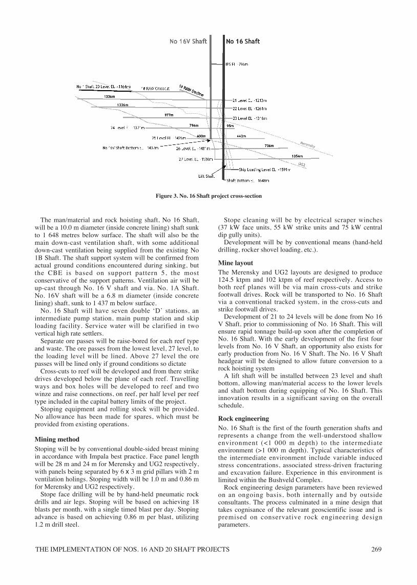
MiningNo. 16 Shaft is planned to produce 226.5 ktpm per monthof reef from seven operational levels, as shown in Figure 3.The levels will access both the Merensky and UG2 reefhorizons, with the emphasis being on mining the MerenskyReef. Waste production is planned at 13% of reefproduction. The mining calendar is based on 23 days permonth for development and stoping.
Figure 1. Location of No. 16 and No. 20 Shaft within the Impala lease area
Figure 2. Three-dimensional seismic survey
1# 9# 10#
5#11#
14#
7#
7A#
6#8#
12#
14A#Dec.
20#Project
16#Project
11C#
12S
12N
4#
2/2A#
Fault
‘Slump’ StructureBh 6293
‘Slump’ StructureBh 6260
Scissor Fault
Undulating Reef
Horst and Graben Structure
Fault Bounded Boundary with 1 Shaft
Economic Resource Reserve Reserve Reserve metalhorizon tons (t) tons (t) grade (g/t) content (kg)
Merensky 17 625 882 23 904 119 4.22 100 849UG2 15 924 895 23 654 274 4.02 95 033Total 33 550 777 47 558 393 4.13 195 882
Table IResources and reserve estimates No. 16 Shaft
THE IMPLEMENTATION OF NOS. 16 AND 20 SHAFT PROJECTS 269
The man/material and rock hoisting shaft, No 16 Shaft,will be a 10.0 m diameter (inside concrete lining) shaft sunkto 1 648 metres below surface. The shaft will also be themain down-cast ventilation shaft, with some additionaldown-cast ventilation being supplied from the existing No1B Shaft. The shaft support system will be confirmed fromactual ground conditions encountered during sinking, butthe CBE is based on support pattern 5, the mostconservative of the support patterns. Ventilation air will beup-cast through No. 16 V shaft and via. No. 1A Shaft. No. 16V shaft will be a 6.8 m diameter (inside concretelining) shaft, sunk to 1 437 m below surface.
No. 16 Shaft will have seven double ‘D’ stations, anintermediate pump station, main pump station and skiploading facility. Service water will be clarified in twovertical high rate settlers.
Separate ore passes will be raise-bored for each reef typeand waste. The ore passes from the lowest level, 27 level, tothe loading level will be lined. Above 27 level the orepasses will be lined only if ground conditions so dictate
Cross-cuts to reef will be developed and from there strikedrives developed below the plane of each reef. Travellingways and box holes will be developed to reef and twowinze and raise connections, on reef, per half level per reeftype included in the capital battery limits of the project.
Stoping equipment and rolling stock will be provided. No allowance has been made for spares, which must beprovided from existing operations.
Mining methodStoping will be by conventional double-sided breast miningin accordance with Impala best practice. Face panel lengthwill be 28 m and 24 m for Merensky and UG2 respectively,with panels being separated by 6 x 3 m grid pillars with 2 mventilation holings. Stoping width will be 1.0 m and 0.86 mfor Merensky and UG2 respectively.
Stope face drilling will be by hand-held pneumatic rockdrills and air legs. Stoping will be based on achieving 18blasts per month, with a single timed blast per day. Stopingadvance is based on achieving 0.86 m per blast, utilizing1.2 m drill steel.
Stope cleaning will be by electrical scraper winches (37 kW face units, 55 kW strike units and 75 kW centraldip gully units).
Development will be by conventional means (hand-helddrilling, rocker shovel loading, etc.).
Mine layoutThe Merensky and UG2 layouts are designed to produce124.5 ktpm and 102 ktpm of reef respectively. Access toboth reef planes will be via main cross-cuts and strikefootwall drives. Rock will be transported to No. 16 Shaftvia a conventional tracked system, in the cross-cuts andstrike footwall drives.
Development of 21 to 24 levels will be done from No 16V Shaft, prior to commissioning of No. 16 Shaft. This willensure rapid tonnage build-up soon after the completion ofNo. 16 Shaft. With the early development of the first fourlevels from No. 16 V Shaft, an opportunity also exists forearly production from No. 16 V Shaft. The No. 16 V Shaftheadgear will be designed to allow future conversion to arock hoisting system
A lift shaft will be installed between 23 level and shaftbottom, allowing man/material access to the lower levelsand shaft bottom during equipping of No. 16 Shaft. Thisinnovation results in a significant saving on the overallschedule.
Rock engineeringNo. 16 Shaft is the first of the fourth generation shafts andrepresents a change from the well-understood shallowenvironment (<1 000 m depth) to the intermediateenvironment (>1 000 m depth). Typical characteristics ofthe intermediate environment include variable inducedstress concentrations, associated stress-driven fracturingand excavation failure. Experience in this environment islimited within the Bushveld Complex.
Rock engineering design parameters have been reviewedon an ongoing basis, both internally and by outsideconsultants. The process culminated in a mine design thattakes cognisance of the relevant geoscientific issue and ispremised on conservative rock engineering designparameters.
Figure 3. No. 16 Shaft project cross-section

PLATINUM SURGES AHEAD270
Ventilation and refrigeration
Ventilation and refrigeration systemGlobal vent/cooling balances have been evaluated, utilisingthe proprietary VUMA software. For the design year of2028, when strike distances are about 1 800 m out (northand south), the global mine energy balance is satisfied if thetotal primary ventilation of 900 kg/s is cooled to 4°Cwb onsurface. This relates to an overall flow factor of 3.6 kg/s perktpm of rock (reef and waste).
Carrying capacity of No. 16 Shaft is limited by maximumdesign air speeds of 10.5 m/s for conveyance stability.Furthermore, the ventilation design is premised onsynergies with neighbouring No 1 Shaft. The up-cast air
flow requirement of 900 kg/s will be achieved by up-casting 650 kg/s via No 16 V Shaft and 250 kg/s via No 1AShaft.
Virgin rock temperatures (VRT) will vary from 49°C (21level) to 57°C (27 level) resulting in a total refrigerationrequirement of 40 MW. 30 MW of the total 40 MWrefrigeration requirement will be provided from the No. 16Shaft refrigeration plant, while the remaining 10 MW willbe supplied from No. 1B Shaft.
The ventilation and cooling system design willincorporate high degrees of flexibility; modular systemswill be applied, which can be phased in with maximumdelay in capital expenditure. In addition, the refrigerationsystem will allow cooling carrying capacity of the down-cast shaft to be maximized. Recent studies at Impala havehighlighted the benefits of using systems with ultra-cold airfor deep workings. This led to the first system beinginstalled and successfully operated at No. 1B Shaft. Thesystem is based on making very cold water, which willcomprise base-load equipment prechilling water prior todelivery to an ice/thermal storage dam containing tubebanks. Ice forms on the outside of the tubes during the coldpart of the day and then melts during the critical warm partof the day. This principle allows design of the system foraverage rather than peak loads, leading to significant capitalcost savings. The refrigeration plant at No. 16 Shaft willhave an installed capacity of 24 MW, utilizing an icemaking plant, similar to that used at No. 1B Shaft. Theplant will comprise four refrigeration modules, identical tostandard Impala refrigeration modules. Cold water willleave the system at temperatures close to 0°C.
The chilled cold air will be distributed to the stopes via anon-reef airway on the Merensky Reef horizon and cross-cuts on levels 24 to 27, as shown schematically in Figure 5.Ventilation air will be returned to No. 16 V Shaft via thestopes to strike reef drives, cross-cuts and dedicated on reefreturn airway (RAW). As ventilation requirements increaseat No. 16 Shaft and decrease at No. 1 Shaft, down-cast airwill be increased from 700 kg/s to 900 kg/s, utilizing No.1B Shaft. Up-cast capacity will be increased utilizing No.1A Shaft.
Figure 4. Isometric view of mine layout and shaft infrastructure
Figure 5. Schematic representation of ventilation distribution system
21 L
22 L
23 L
24 L
25 L
26 L
27 LG
245 kg/s ON REEF AIRWAY
9
9
9
30 MWR10 MWR
NO
. 16V
SH
AF
TN
O. 1
6V S
HA
FT
NO
. 1A
SH
AF
T25
0 kg
/s
NO
. 1B
SH
AF
T20
0 kg
/s
650
kg
/s
700
kg
/s
GG
G ONLY MERENSKEY SHOWN
ONLY NORTH FACESHOWN
THE IMPLEMENTATION OF NOS. 16 AND 20 SHAFT PROJECTS 271
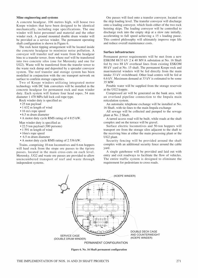
Mine engineering and systemsA concrete headgear, 106 metres high, will house twoKoepe winders that have been designed to be identicalmechanically, including rope specifications. The onewinder will hoist personnel and material and the otherwinder rock. A ground mounted double drum winder willbe provided as a service winder. The permanent operatingshaft configuration is shown in Figure 6.
The rock hoist tipping arrangement will be located insidethe concrete headgear to minimize noise pollution. Aconveyor will transfer reef and waste from the headgearbins to a transfer tower, from where reef will be transferredinto two concrete silos (one for Merensky and one forUG2). Waste will be transferred from the transfer tower tothe waste rock dump and deposited by a spreader conveyorsystem. The reef transfer and storage system has beenmodelled in conjunction with the ore transport network onsurface to confirm storage capacities.
Two of Koepe winders utilizing integrated motortechnology with DC link converters will be installed in theconcrete headgear for permanent rock and man winderduty. Each system will feature four head ropes, 54 mmdiameter 1 470 MPa full lock coil rope type.
Rock winder duty is specified as:• 25 ton payload • 1 632 m length of wind • 16 m/s rope speed • 6.5 m drum diameter • A motor duty cycle RMS rating of 4 815 kW.
Man winder duty is specified as• 22.5 ton payload (300 persons)• 1 591 m length of wind• 16m/s rope speed• 6.5 m drum diameter• A motor duty cycle RMS rating of 2 536 kW.
Trains, comprising 10-ton locomotives and 6-ton hopperswill haul rock from the stope ore passes to the tip/orepasses, located in the main cross-cuts on each level.Merensky, UG2 and waste ore passes are provided to allowunencumbered transport of reef and waste throughindependent systems.
Ore passes will feed onto a transfer conveyor, located onthe skip loading level. The transfer conveyor will dischargeonto a loading conveyor, which feeds either of the two rockhoisting skips. The loading conveyor will be controlled todischarge rock into the empty skip at a slow rate initially,accelerating to full speed achieving a 15 s loading pause.This control philosophy will ultimately improve rope lifeand reduce overall maintenance costs.
Surface infrastructurePermanent power requirements will be met from a newESKOM 88/33 kV 2 x 40 MVA substation at No. 16 Shaftfed by two 88 kV overhead lines from existing ESKOM 88 kV yard at No. 15 shaft. The permanent Koepe rock andman/material winders will be fed directly from the mainintake 33 kV switchboard. Other load centres will be fed at6.6 kV. Maximum demand at 33 kV is estimated to be some35 MW.
Potable water will be supplied from the storage reservoirat the UG2 koppie.
Compressed air will be generated on the bank area, withan overland pipeline connection to the Impala mainreticulation system.
An automatic telephone exchange will be installed at No.16 Shaft, with tie-lines to the main Impala exchange
All sewage will be collected and pumped to the sewageplant at No. 2 Shaft.
A tarred access road will be built, while roads at the shaftcomplex and on the terrace will be gravel.
Surface electric locomotives and 50-ton hoppers willtransport ore from the storage silos adjacent to the shaft tothe receiving bins at either the main processing plant or theUG2 plant.
Security fencing will be provided around the shaftcomplex with an additional security fence around the cableyard.
A single gatehouse will be provided and laid out withentry and exit roadways to facilitate the flow of vehicles.The entire traffic system is designed to eliminate therequirement for pedestrians to cross roads.
Figure 6. No. 16 Shaft permanent configuration
DOUBLE DECK CAGEAND COUNTERWEIGHT(KOEPE WINDER)
SERVICE CAGE(DOUBLE DRUM WINDER)
(KOEPE WINDER)
PERMANENT CONFIGURATION

PLATINUM SURGES AHEAD272
The bank area has been laid out to allow for easy ropechanging, using a mobile heavy duty friction winch.
Capital costCapital cost for the project is estimated at R2 561 115 atbase date of June 2004, escalated to R3 650 000 atcompletion of the project.
Project programmeThe project master programme was derived from firstprinciples, based on the experience of the project teams.Input was also obtained from contractors as and whererequired and reviewed both internally and externally. Keydates from the programme are summarized in Table II. Theprogramme was extensively reviewed internally andthrough a third party audit.
Project implementationProject execution is by a conventional engineering,procurement and construction management (EPCM)contractor, overseen by a relatively small Impala owner’steam.
The project is currently ahead of schedule and underbudget.
Subsequent to the project approval, the followinginitiatives assisted to speed up the programme:
• An early start was made on the ventilation shaft sinkingby employing the shaft sinking contractor’s winders forsinking in preference to purchasing new winders as hadbeen planned and budgeted
• By doing the initial presink to the collar position of themain shaft by means of a box-cut and six wheelervehicles in preference to conventional sinking anearlier start could be made on the presinking operation
• Employing a putzmeister concrete pump to pumpconcrete vertically up the headgear during constructionin preference to the conventional crane and ‘shoe’arrangement resulted in an earlier start on the mainshaft sinking operations.
No. 20 Shaft project
LocationThe No. 20 Shaft project is located north of No.12 Shaft onthe north-west corner of the Impala mining lease area onthe farms Boschkoppies 104JQ and Goedgedacht 110JQ.The project incorporates an area approximately 3.0 km onstrike and 3.5 km on dip and represents the last remainingreserve within the current mining lease area that can still beclassified as being shallow i.e. less than 1 000 m belowsurface.
GeologyThe No. 20 Shaft mining area is underlain by the pyramidgabbro-norite (main zone) and the mathlagame norite-anorthosite (critical zone), Rustenburg layered suites of theBushveld Complex. The Merensky Reef and the UG2chromitite layer located in the upper critical zone are thetwo exploitable economic horizons within the lease area.
Geological interpretations and the projection of thecomplex structures across the mining area have beenprimarily derived from geophysical and 3D seismicinterpretations and confirmed by superimposing explorationboreholes onto the seismic lines, directly affecting thecalculation of reserves.
Analysis of this information has revealed a complexstructural regime for the No. 20 Shaft area.
Both the Merensky Reef and UG2 chromitite layer strikein a NW-SE direction and dip to the east (between 2° and12° ) to an elevation of 1 177 mbc (metres below collar)and 1 237 mbc respectively. These variable dips and therolling nature of the reef horizons are primarily responsiblefor the irregular reef contours. The vertical separationaverages 65 m and ranges from 27 m to 92 m due tofaulting, potholing and thickness variations on strike anddip.
Mining accessThe shaft system will comprise an 8.5 m diameter (depth 1 051 m) downcast, man, material and rock shaft togetherwith one upcast ventilation shaft of 6.5 m diameter (depth977 m). These shafts are strategically positioned, relative tothe orebody, to access each of two reef planes byestablishing a triple decline system.
The main shaft will provide capacity to hoist up to 241 000 tons per month of ore and waste. The ventilationshaft will transfer 650 kg/s of refrigerated air to theworkings.
A multiple decline access system parallel to the plane ofthe reef has been proposed to provide men and materialsaccess, rock handling and logistical services to production.This access system was chosen to accelerate the time to fullproduction.
The conventional rail bound rock transport system,positioned in the footwall below the reef on each mininglevel will provide reliable, cost-effective productionperformance. This system provides some flexibility tonegotiate the frequent reef displacements caused byfaulting. Operational and maintenance skills are available atexisting Impala operations for rail haulage.
A footwall decline situated close to the central axis of thereserves, equipped with a high capacity conveyor willtransfer rock from the haulage ore passes to the rockloading facilities at the hoisting shaft. Surface silos willstore the rock for loading to the surface rail system fordelivery to the concentrator.
Activity Start Complete
Approval to first production 01/10/2004 17/08/2011Ramp-up to full production 17/08/2011 31/10/2014
No 16 ShaftNo 16 Shaft Main Sink 03/05/2006 25/06/2010No 16 Shaft Equipping 28/06/2010 06/03/2011
No 16 V ShaftNo 16 V Shaft Headgear 20/09/2006 31/03/2006No 16 V Shaft Main Sink 03/04/2006 14/10/2008
Table IIKey dates No. 16 Shaft
Economic Resource Reserve Reserve Reserve metalhorizon tons (t) tons (t) grade (g/t) content (kg)
Merensky 20 880 011 23 002 047 3.77 86 748UG2 9 457 619 15 117 785 3.15 53 023Total 30 337 630 38 119 832 3.67 139 771
Table IIIResources and reserve estimates No. 20 Shaft

THE IMPLEMENTATION OF NOS. 16 AND 20 SHAFT PROJECTS 273
Mining methodThe proposed mining method is essentially a systemcombining conventional mining and support methods in thestopes and footwall drives as on existing shafts, andmechanized mining methods in the decline development.This system makes use of conventional hand-held rockdrillsfor the drilling and blasting cycle with scraper winchcleaning on stoping, and conventional tracked locomotiveand loader cleaning and tramming to ore passes on strikefootwall drives.
The envisaged mining method has been selected for No.20 Shaft for the following reasons:
• rapid access, improved logistics and ramp-up to fullproduction
• provision of an early exploration platform for moredetailed orebody definition within the ramp-up phase
• rapid reestablishment ability on strike beyondgeological discontinuities
• lower technical and financial risk with provenequipment and good cost information availability fromcurrent operations at shallow depths.
Mine layoutThe Merensky and UG2 mining layouts are each designedto produce 185 ktpm of ore. Access to the two reef planeswill be via two material declines positioned between theMerensky and UG2 reef planes. Rock will be transported tothe shaft via a conveyor system in a third decline locatedbelow the UG2 plane.
The two material declines are initially developed 5 mwide by 4 m high to provide adequate ventilation forestablishment of the capital footprint. Subsequently theywill be reduced to 4.5 m wide by 4.0 m high. The declineswill be 15 m apart with connecting splits. One decline willhave a chairlift and overhead monorail installed.
The conveyor decline will be developed 6.3 m wide by3.3 m high, allowing for trackless vehicle access alongsidethe conveyor (for conveyor decline development andmaintenance purposes).
Footwall drives will be developed on strike at 1:200gradient and 18 m below the reef plane, using conventionaltracked locomotive and loader techniques.
The reef true dip is 8° and the declines will be developedat an apparent dip averaging 6.5°.
The strike footwall drive dimensions will be 3.5 m wideand 3.3 m high.
Within the capital footprint, the initial on reefdevelopment will enable a quicker ramp-up to fullproduction. When the full capital footprint is established,this development will convey ventilating air in sufficientquantities to the workings in block B and return thecontaminated air to the ventilation shaft from block A. Thefuture reef access raises are developed parallel to the dipfault bracket pillars. The ASGs are developed from thesereef raises and kept within 2.5 m to 3 m ahead of the breastpanels.
Each stope connection on the Merensky plane will serveon average seven stope panels of 30 m open span includingthe ASG.
In-stope drilling will be by pneumatic rock drills and air-legs using 1.5 m drill steel followed by conventionalscraper winches cleaning. The raises are expected onaverage to have true dip back lengths approaching 200 mbetween strike footwall drives with a dip gully scrape ofaround 165 m.
Rock engineeringThe regional support system is a combination of faultbracket pillars, potholes and replacement pegmatoid bodiesdesigned to compartmentalize the mine and eliminate plugfailure. These regional support pillars in conjunction withyielding in-panel grid pillars stabilize the stope hanging-wall up to the bastard Merensky parting plane or UG2leaders.
The No. 20 Shaft regional support pillars are strike anddip orientated, incorporated into the fault bracket pillars atvarious intervals not exceeding 400 m on strike. The pillarshave been designed using numerical modelling.
The off-reef material and conveyor declines (diporientated) and footwall drives (strike orientated) arelocated deep enough in the footwall to cater for fluctuationsand undulations of the reef plane during development andto be unaffected by increased stresses due to stoping.
Figure 7. Cross-section of shafts and declines

PLATINUM SURGES AHEAD274
The main material declines are planned at 30 m below theMerensky reef plane; the Merensky and UG2 conveyordecline is planned at 30 m below the UG2 reef plane. TheMerensky and UG2 strike footwall drives are positioned at18 m below the reef plane.
The need for a shaft protection pillar has been assessedfollowing the conclusion of a numerical modellingevaluation conducted by a specialist external rockengineering consultancy. It has been decided to pre-extractthe shaft pillar on the Merensky reef horizon on the mainshaft and the UG2 shaft pillar on the ventilation shaft. TheMerensky shaft pillar on the ventilation shaft will not bepre-extracted to ensure a sealed return airway and toprevent short-circuiting of intake ventilation. The UG2shaft pillar will not be extracted as the geotechnicalborehole has indicated the reef as being replaced. Furthermodelling work has been completed to assess the stabilityof major off-reef excavations such as workshops, pumpchambers and airways located near the shaft.
Ventilation and refrigerationBulk cooled air is generated on surface and supplied intothe downcast main shaft via sub-bank ducting. The chilledair is distributed to the stopes underground via the mainmaterial declines and the strike footwall drives.
A downcast air quantity of 650 kg/s is adequate for thedilution of all air pollutants and contaminants and heatremoval during mining. The required quantity of air is mostsensitive to the mine reject wet-bulb and dry-bulbtemperatures and the virgin rock temperature (VRT) atwhich mining is taking place.
The principal ventilation infrastructure (shafts andairways), will be fully utilized when full production isattained. Little or no residual ventilation capacity will beavailable to increase production beyond 185 ktpm of ore.
The requirement to downcast 650 kg/s of fresh air resultsin a full production air factor of 3.2 kg/s per ktpm of rockbroken.
The workings are ventilated by a semi flooding typeventilation system and the return air is exhausted up theventilation shaft, from the stopes, via a combination ofstrike footwall drives from block B and the on-reefMerensky access decline from block A. This on-reefdecline is used to accelerate the early tonnage build-up.
Mining is divided into four geographical ventilationdistricts. Air will intake on the footwall located materialdeclines in both a western (up-dip) and eastern (down-dip)direction to the furthest two or three strike footwall drivesfrom where it will flow to the working faces north andsouth. The aim is to introduce, on the production levels inblock B, furthest from the shaft complex, as much fresh airas possible. The in-stope dip ventilation controls will be theblast barricades, and single and double ventilation curtains.Velocities in excess of 1.0 m/s are envisaged at about 3 mfrom the stope faces. The air will flow up dip along all thestope faces and return down dip in the worked out areas andthe on-reef access decline to the upcast ventilation shaft.
Air velocities in the downcast and upcast shafts, at collarelevation, are calculated at 11.5 m/s and 19.9 m/srespectively.
The collar and sub-bank shaft air intake is capable ofhandling 650 kg/s. Of this amount up to 600 kg/s will passthrough the bulk air cooler and the balance of 50 kg/sthrough the collar from the bank area.
Cooling infrastructure for the mine will be created in twophases, with first cooling required in about 2010. Full
production will be reached by 2011, at which time 550 kg/sof chilled air will be required. The need for coolinggradually increases as production progresses further awayfrom the shaft complex and to greater depths. In the period2020 to 2025 the refrigeration machine capacityrequirement will be about 22 MW(R). Merensky miningwill be to a depth of 1 177 mbc at a VRT of 49.8°C. UG2mining will be to a depth of 1 237 mbc where the VRT is51.2°C
Shaft infrastructureThe permanent headgear will be a 50 m high steel A-frametype structure (450 tons) serving three winders (rock,man/material, service) using five compartments in the mainshaft (twin skips, cage and counterweight, and singleservice cage).
The rock hoist tipping arrangement in the headgear willhave a transfer bin with a storage capacity of approximatelyeleven skip loads. Conveyors will remove hoisted rock on acontinuous basis to either of two concrete storage silos orbeyond to the waste rock dump.
Rock hoisting skips will be of the bottom discharge typewith a payload of 15 tons.
The man/material compartments will be serviced by onelarge single deck conveyance capable of handling 150persons per trip or a low profile LHD with a mass of up to15 tons. The single service conveyance will comprise twodecks with a capacity of 11 persons per deck.
WindersThe rock winder will be of the double drum type with awinding speed of 15 m/s and a hoisting capacity of 450 tonsper hour (tph). Hoisting will take place six days per weekwith an availability of 75% and utilization of 95%. Thewinder will operate automatically but facility for manualoperation will be provided.
The man/material winder will also be of the double drumtype with a winding speed of 12 m/s and a single deck cagewith capacity of 150 persons or 15 tons payload. Thewinder will be operated manually.
The service winder will be of the single drum type with awinding speed of 7 m/s and a double deck cage (22 persons). The winder will be operated manually.
Underground rock handlingTrains, comprising of 10 ton locomotives and 6 ton hopperswill haul the rock from the stope ore passes to the stationtips above the conveyor decline. The rock is conveyed tothe shaft rock handling system consisting of surge ore andwaste passes and skip loading transfer conveyor. Reef andwaste will be handled separately by campaign.
The Merensky and UG2 conveyor decline, located in thefootwall of the UG2 reef horizon, will convey ore to theshaft. Shuttle conveyors at the discharge of the conveyordecline will transfer ore or waste to their respectivepasses.These conveyors will be 1 200 mm wide, anddesigned to handle 600 tph.
The loading station conveyor (126 m long) will be 1 200 mm wide, designed to run at a speed to match thewinding cycle, and loading 15 ton measuring flasks fortransfer of rock to the skips for hoisting to surface.
Ore feeding onto the conveyors from the ore passes willbe controlled by chutes and gates operated by compressedair cylinders. Vibrating feeders will control the flow rate.

THE IMPLEMENTATION OF NOS. 16 AND 20 SHAFT PROJECTS 275
LHDs and drill rigs will be used for infrastructure anddecline development. Air loaders will be used fordevelopment in the strike footwall drives.
Materials handlingShaft service vehicles include forklifts, small cranes,shunters, material cars and delivery vehicles. Transportfrom the surface to underground will be undertaken usingmaterial transport cars.
Material handling on the main level is facilitated by amaterial loop to access shaft conveyance from both sides.
The material transport cars will be marshalled on themain access station for distribution to production levels viathe monorail system. Forklifts will be used to load andunload pallets with material. It is expected that further workwill be done on materials handling to optimize the finaldesign during the detailed design phase.
A number of LHDs, drill rigs and rock bolters will beused to develop the declines, supported by a fleet of utilityvehicles.
Mono winches will be used for transporting supplies intothe stopes.
Personnel transporters will be available at shift times andfor use by maintenance personnel.
A chairlift will be installed to transport men to theextremities on dip, while travelling on strike will be byfoot.
Underground workshop and storeA centralized workshop will provide for all services andrepairs to all vehicles underground. The workshop will besituated close to the main shaft and underground mainstore.
The satellite service and battery bays will be establishedon each level to limit the number of production vehiclestravelling long distances for servicing.
Drill rigs and roofbolters for decline development will beserviced in a bay close to the respective workplaces. Majorrepairs and overhauls will be done in the main workshop onthe main level.
Maintenance stock levels will be kept undergroundinstead of on surface. Availability to the user should bequick without having to lose a shift waiting for componentsfrom the surface store.
Bulk items for production will remain on the normalorder and delivery from surface, as is the usual practice.
Services pipingService and potable water are supplied from surface to therespective production sections in blocks A and B via acascade system utilizing separate pipelines. Water will besupplied from each cascade dam directly to the respectiveproduction sections below the dam.
Compressed air generated on surface is supplied to theproduction section via a column in the main shaft and bypipe through airways/declines up to general services andstoping sections. A connection from the shaft will form alimited ring feed, which will improve air pressures in theproduction sections.
Mine return water is pumped to surface after being settledunderground, for recirculation. Settler underflow is pumpedto surface for settling and evaporation in dedicated storagedams. Some water will be returned to the undergroundworking areas.
Surface infrastructureThe main electrical power supply will be taken from theESKOM substation at 33 kV. The supply will be byoverhead lines in a ring formation. Two 33/6.6 kV, 20 MVA transformers will be installed at the No. 20 Shaftconsumer substation.
Potable water to No. 20 Shaft will be supplied via apipeline.
Compressed air will be generated from three centrifugalcompressors. An overland pipeline connection to theImpala main reticulation system will be constructed inaccordance with Impala’s overall compressed air strategy.
An automatic telephone exchange will be installed at theshaft, with tie-lines to the main Impala exchange.
All sewage will be routed to a collection point fromwhere it will be pumped to existing Impala facilities.
A 2.3 km tarred access road will be built, whilst all roadsaround the shafts and on the terrace will be gravel.
A single gatehouse will be provided and laid out withentry and exit roadways so as to facilitate the flow ofvehicles with a minimum of delay and interference withpedestrians. Pedestrian access will be via turnstiles withsecurity badge readers.
Figure 8. A 3-D depiction of underground infrastructure
Activity description Start Finish
Project ‘Go Ahead’ 01-Oct-04 N/ASurface terrace construction 13-Oct-04 19-Apr-05Main shaft collar construction and presink 12-Nov-04 05-Oct-05Main shaft equipping and commissioning 7-Apr-08 14-Jan-09Vent shaft collar construction, presink 24-Nov-04 12-Aug-05Vent shaft headgear installation 09-May-05 07-Oct-05Vent shaft sinking 08-Oct-05 25-Sep-07Vent shaft material and conveyor declines 26-Sep-07 24-Nov-08and ramps developVent shaft changeover 25-Nov-08 9-Jan-09Production start 15-Jan-09 Full production 15-May-11
Table IVKeydates No. 20 Shaft

PLATINUM SURGES AHEAD276
Project programme
Capital estimatesCapital cost for the project is estimated at R2 088 611 atbase date of April 2004, escalated to R3 000 000 atcompletion of the project.
Project implementationProject implementation is by a conventional engineering,procurement and construction management (EPCM)contractor overseen by a relatively small Impala owner’steam.
The project is currently ahead of schedule and underbudget.
Subsequent to the project approval, the followinginitiatives assisted to speed up the programme:
• By utilizing the synergy from combining the civil andmining contractors, both of whom came from the sameparent company, the surface infrastructure preparationcould be completed ahead of schedule and the sinkingoperation commenced ahead of schedule
• An early start was made on the ventilation shaft sinkingby employing the shaft sinking contractor’s winders for
sinking in preference to purchasing new winders as hadbeen planned and budgeted
• An early start was made on the main shaft sinking bypurchasing a secondhand rock winder from a gold mineand employing this as a kibble winder initially, inpreference to purchasing a new winder as had beenplanned and budgeted
• Use was made of the permanent headgear and winderfor sinking purposes.
ConclusionBoth projects are progressing ahead of schedule and underbudget. At the time of writing (May 2006), the respectiveshafts had reached the following depths:
20 Ventilation shaft = 843 m20 Main Shaft = 765 m16 Ventilation Shaft = 515 m16 Main Shaft = 225 mWhile No. 20 Shaft project has been free of any water,
some intrusions have been experienced on both the shafts atNo. 16 Shaft project. Normal cementation procedures havebeen used to seal these as they have been encountered.