the improved thermal conductivity of a potting material
TRANSCRIPT

The Improved Thermal Conductivity of a Potting Materialfor High-Power Fast Warm-Up Cathodes
Xiaodong Zhang, Junjie Hao, Zhimeng Guo, Zhenhui Ji, Ji Luo, Cunguang Chen, Fang Yang, and Alex A. Volinsky
(Submitted December 18, 2017; in revised form August 29, 2018; published online November 27, 2018)
With higher power, frequency and longer life of microwave tubes, cathode heater assembly is beingmodified to enhance the warm-up performance and reliability, which are governed by ceramics thermalconductivity, electrical resistivity and shrinkage. In present work, a potting material with a high thermalconductivity of 22.14 W/(m K) and low linear shrinkage of 5.5% was prepared using two kinds of aluminapowders with different size and morphology. Aqueous slurries were produced for centrifugal casting. Thehighest solid loading slurries with 70 vol.% were obtained. Green body with relative density above 70%was easily made from slurries using centrifugal casting. Relative sintered density reached 86.75% maxi-mum without any sintering aids. Rheological behavior of slurries, potting microstructure, sinteringshrinkage and thermal conductivity were analyzed. Continuous particle distribution, series and parallelmodels were used to guide the powders proportion and explain the thermal conductivity. The pottingmaterial thermal conductivity experimental data agreed with the series and parallel models when theweight parameter n was between 0.3 and 0.5.
Keywords centrifugal casting, fast warm-up cathodes, high solid-loaded slurries, high thermal conductivity, low linershrinkage
1. Introduction
Fast warm-up traveling-wave tubes are widely used inmilitary and aerospace applications, including electronic war-fare, missile seekers and conventional radars with the cathodereaching its maximum electron emission in several seconds(Ref 1). The dielectric potting material (Fig. 1(4)) is used topackage a coiled filament wire (Fig. 1(3)) and a supportcylinder (Fig. 1(2)), which collectively form the heater assem-bly. Generally, the cathode (Fig. 1(1)) brazed to the supportcylinder is indirectly heated to produce thermionically emittedelectrons.
Voltage is applied to the filament in 10�8 Torr vacuum toraise its temperature to at least 1050-1200 �C in a few secondsto provide the thermal energy to promote thermal electronemission from the cathode. The heater assembly geometry isshown in Fig. 1. The thermal conductivity and linear shrinkageof the potting material directly determine the warm-up prop-erties, lifetime and reliability of traveling-wave tubes (Ref 1).The linear shrinkage of the potting material controls thesintering shrinkage and the thermal expansion.
The most desired qualities of such potting materials aremaximum thermal conductivity, high electrical resistivity, the
proper coefficient of thermal expansion (CTE) and minimumshrinkage during drying/firing without any undesirable reactiv-ity toward surrounding metals (Ref 2). Due to the smalldimensions of the heater assembly (3-15 mm), the shrinkage of5-15% is much larger during sintering (Ref 2-5), so only theshrinkage during sintering of the potting materials is discussedin the present work. Alpha-alumina (a-Al2O3) is one of thewidely used potting materials because of its abundance andunique mechanical, electrical and thermal properties (Ref 2, 3).There is currently no alternative potting material, which cancompletely substitute alumina. Alternative potting materialsmust meet fast warm-up time requirement, conduct heat fasterand withstand much higher thermal stresses than standardalumina (Ref 1, 3).
Intensive research has been carried out toward obtaining apotting material with higher thermal conductivity and density.Various formulations and mixes of different grit size dopedalumina and modifications of potting and sintering processesare used to reduce shrinkage and crack formation. Thus, thepotting mixtures are denser and capable of withstanding fastheating (Ref 1-5).
Orlowska (Ref 1) demonstrated alumina-based pottingceramics, which would conduct heat faster. Wolverton et al.(Ref 5) demonstrated 97% alumina composition with thermaldiffusivity of 1.12 mm2/s at room temperature. Swartzentruberet al. (Ref 3) showed that Al2O3/AlN/CaO had 3 W/(m K)thermal conductivity. Kalyan et al. (Ref 2) reported that 1 wt.%CaO-doped Al2O3 samples had a higher thermal conductivityof 19.44 W/(m K) at 200 �C with low 2.89% shrinkage anddecreased electrical resistivity.
Not enough liquid phase would concomitantly result inceramics shrinkage with delamination and tiny cracks betweenpotting and the support cylinder during sintering. However,excess liquid solution decreases the electrical resistivity ofpotting mixtures (Ref 2), which could reduce the reliability ofthe heater assembly.
With the quest for microwave tubes with higher power and/orhigher frequencies, longer life or combinations of these, cathode
Xiaodong Zhang, Junjie Hao, Zhimeng Guo, Zhenhui Ji, Ji Luo,Cunguang Chen, and Fang Yang, Institute for Advanced Materialsand Technology, University of Science and Technology Beijing, 30Xueyuan Road, Haidian District, Beijing 100083, China; andAlex A. Volinsky, Department of Mechanical Engineering,University of South Florida, Tampa, FL 33620. Contact e-mails:[email protected] and [email protected].
JMEPEG (2018) 27:6701–6708 �ASM Internationalhttps://doi.org/10.1007/s11665-018-3760-5 1059-9495/$19.00
Journal of Materials Engineering and Performance Volume 27(12) December 2018—6701

heater assembly has to be modified to improve performance andreliability, which are governed by ceramics thermal conductivity,electrical resistivity and density (Ref 6). Improving thermalconductivity and density of standard alumina potting without toomany additions and with low shrinkage is of great interest.
Usually, the heater assembly is formed centrifugally using aceramic slurry, wire and the support cylinder, and then dried andsintered together. According to the wet forming theory, highsolid-loaded alumina slurries with low viscosity are conducive toincrease potting density. Theoretical (Ref 7-13) and experimentalresearch reports (Ref 13-24) demonstrate that proper particle sizedistribution can significantly improve properties of the solid-phase slurry, improve particle accumulation and increase greenbody density. On the other hand, investigations of Heunisch (Ref25) and Wang (Ref 23, 26) showed that slurries made withspherical particles exhibit lower viscosity with similar particleloading and green body, leading to higher green density thanplatelet-shaped particles and ground powder. Spherical powdersallow easier particle rearrangement and pack more densely (Ref25). In addition, Ferreira et al. (Ref 20, 27) and Taruta et al. (Ref21) have shown for Al2O3 that it is possible to obtain high-density slip cast bodies by using bimodal powder size distribu-tion (PSD), in which fine and coarse powders are combined withan appropriate proportion and size ratio. In particular, Tari et al.(Ref 27) demonstrated obtaining high solid-loaded aluminaslurries with 70 vol.% and different PSD.
In the present work, both different particle size distributionand spherical particles are used to produce high solid-loadedalumina slurries with low viscosity, which has not beenreported previously. The slurries were produced for centrifugal
casting, and their rheological behavior was analyzed. Thermalconductivity and density of the standard alumina potting wereinvestigated experimentally and correlated with microstructure.
2. Experimental Procedure
2.1 Powder Characterization
Spherical alumina powder (SAP) and irregular-shape alu-mina powder (IAP) with a different particle size (PS) and shapewere used as starting materials of the slurries for the pottingprocess. SEM morphology of the powders is shown in Fig. 2.The IAP powder contains irregularly shaped particles, while theSAP powder is spherical with almost 90% spheroidization. TheIAP powder was obtained from Denka, Tokyo, Japan. Incontrast, the particles for the SAP powder were prepared by theauthors using plasma spheroidization in the RF thermal plasmareactor from the IAP powder. The particle size distribution andthe specific surface area of all powders were determined bylaser granulometry (Mastersizer 2000, Malvern Instruments,Worcestershire, UK) after powder dispersion by ultrasonictreatment and addition of ammonium citrate (SinopharmChemical Reagent Beijing Co., Ltd, China) as a dispersant.The particle shape was characterized by scanning electronmicroscopy (SUPRA 55, Carl Zeiss Company, Germany).
2.2 Slurry Preparation
From these powders, slurries with 60-70 vol.% solid contentwere prepared. Deionized water was used as a solvent andammonium citrate (AC), or polycarboxylic acid (PC) was addedas a dispersant. All dispersants are completely water-soluble andwere provided by the manufacturers in the aqueous solutionform. Then, the pH value of deionized water was adjusted to 10-11 by adding ammonia. Two kinds of alumina powders wereblended in different proportions with the solvent. For completedeagglomeration of the powder particles, the slurries with solidcontent were milled in a ball mill for 12 h. Subsequently, theslurry was sieved through a 200-lm mesh screen and degassedto remove trapped gas bubbles before centrifugal casting.
Zeta potentials of dilute alumina slurries were measuredusing zeta potential analyzer (Zetasizer Nano ZS, Malvern,Worcestershire, UK). An aqueous suspension was used tomeasure the zeta potential with the solid concentration of about0.02 wt.% using IAP powders. The dispersants were addedbased on the weight of the powder, and then, the pH wasadjusted by HCl and NaOH solutions with corresponding pHvalues of 3 and 11. Rheological behavior was characterizedusing a rotational rheometer (MCR 300, Physica, Germany).The viscosity of the slurries was measured with continuousshear rate, c, increasing from 0.1 to 100 s�1 at 20 �C.
2.3 Centrifugal Casting
Support cylinder and coiled filament wire were washed inacetone, followed by alcohol rinse and post-bake. First, thedegassed slurry was poured into the support cylinder. Then, thewire was inserted into the slurry wrapped by the supportcylinder. They were spun in an aluminum mold for 5 min at2000 g centrifugal force in a centrifuge (Optima L-XP, Beck-man, USA) equipped with swinging buckets. Meanwhile, foreach set of parameters, centrifugal casting alumina potting
Fig. 1 Heater assembly geometry: 1—cathode, 2—support cylinder,3—coiled filament wire, 4—alumina potting
6702—Volume 27(12) December 2018 Journal of Materials Engineering and Performance

samples (/12.5 mm 9 20 mm) were made using a plasticcentrifuge tube. For each sample, the weight and size weremeasured by means of precision scales and micrometer,respectively. The green density was calculated accordingly.
2.4 Samples Sintering
After drying, the heater assembly samples were fired invacuum using the following temperature–time profile: theheating rate of 3 �C/min up to 200 �C, 5 �C/min to themaximum temperature of 1600 �C, 60 min dwell time, fol-lowed by the cooling rate of 5 �C/min under hydrogenatmosphere. Thermal diffusivity was determined using thelaser pulse method by the thermal diffusivity system (LFA447Nanoflash, Germany) of the samples (12.5 mm diameter and2.5 mm thickness) with conductive Au sputter coating on bothsides in the 200-800 �C temperature range. For the sinteredsamples, density and size were determined again. The shrink-age was calculated using the size values in green and sinteredstates.
3. Results and Discussion
Medium particle size d50 of the SAP spherical powder was4.8 lm, and that of the IAP was 1.8 lm. Particle sizedistribution obtained by laser granulometry is shown in
Fig. 3. The distribution of the two kinds of powders has twopeaks with a wide intersection region. Specific surface area ofthe powders was obtained from the data in Table 1.
3.1 Particle Size Distribution Analysis
Two kinds of alumina powders were blended in differentproportions to study particles packing. This introduces avariable w, which is the mass ratio of SAP to IAP. Accordingto the continuous particle distribution model proposed by Funkand Dinger (Ref 9-12, 24), to maximize powder packingefficiency, particle distribution needs to satisfy Eq 1:
wparticle ¼dn � dnmindnmax � dnmin
ðEq 1Þ
where d, dmin and dmax denote the particle size, minimum andmaximum particle sizes, respectively, and wparticle is thecumulative mass fraction of powders with size less than d.
(a)
20 μm
(b)
10 μm
Fig. 2 Scanning electron micrographs of the two as-received alumina powders: (a) SAP; (b) IAP
0.1 1 10 1000
1
2
3
4
5
6
7
8
Volu
me,
%
Particle diameter, μm
IAPSAP
Fig. 3 Particle size distribution of the alumina powders
Table 1 Medium particle size d50 and specific surfacearea of the Al2O3 powders
Powder d50, lm Specific surface area, m2/g
IAP 1.8 1.21SAP 4.8 0.57
101
0
20
40
60
80
100C
umul
ativ
e m
ass
frac
tion,
%
Particle diameter, μm
IAPw=1.5w=2w=2.5w=3SAPTheory
Fig. 4 Particle size distribution of mixed powders and calculatedresults by the Dinger packing model, w = m(SAP)/m(IAP)
Journal of Materials Engineering and Performance Volume 27(12) December 2018—6703

The distribution modulus n is 0.37, given by the Dinger modelfor the three-dimensional conditions. The minimum particlesize was 0.5 lm, and the maximum particle size was 12 lm inthe mixture of IAP and SAP powders. The calculation resultsare shown in Fig. 4, where the mass ratio of SAP to IAP, w, was3-4, and particle size distribution of the mixture is close totheoretical predictions. Table 2 lists potting materials� proper-ties before and after sintering.
3.2 Dispersants Effects on Slurries Properties
According to the extended Derjaguin, Landau, Verwey andOverbeek (DLVO) theory, the properties of the suspensions arenot only controlled by PS and PSD (Ref 27), particle shape (Ref23), solid loading (Ref 28), but also by the interaction forcesbetween suspended particles. Ceramic powders tend to agglom-erate due to the attractive inter-particle van der Waals forces(Ref 28). Appropriate dispersants alter the powder surfaceproperties so that the repulsive forces become higher than theattractive forces and the particles can remain separated insuspension. The repulsive forces consist of either electrostaticrepulsion resulting from the overlapping of electrical doublelayers or steric hindrance resulting from absorption of largemolecules (Ref 29). Dispersants that are functioning via bothelectrostatic and steric mechanisms are called poly-electrolytes,which usually consist of a hydrocarbon chain and a polar ionicpart (COO�, SO3
�) (Ref 30-32). Dispersant addition candramatically reduce the viscosity of slurries with very high
solids content, and thus, ceramic industry has a constantdemand for effective dispersants (Ref 33). Zeta potentialmeasurements are used for preliminary screening amongvarious dispersants, such as AC and PC. An AC molecule
Table 2 Potting materials� properties before and after sintering
w qg, g/cm3 q¢g, % qs, g/cm
3 q¢s, %
e, %
a, mm2/s k, W m21 K21Top Bottom
0:1 2.19 54.75 3.1 77.5 12.25 11.5 6.62 14.781.5:1 2.82 70.5 3.38 84.5 13.8 5.5 8.24 20.052:1 2.79 69.75 3.31 82.75 5.9 5.9 8.66 20.643:1 2.81 70.25 3.47 86.75 6.3 5.5 8.86 22.144:1 2.84 71 3.16 79 6.3 6.7 8.47 19.271:0 2.4 60 2.83 70.75 4.75 4.75 6.5 13.99
qg, q¢g, qs and q¢s represent the green body density, green body relative density, sintered density and sintered relative density, respectively.
2 4 6 8 10 12 14-60
-50
-40
-30
-20
-10
0
10
20 No dispersant
Zeta
pot
entia
l, m
V
pH
0.3wt% AC 0.3wt% PC 0.3wt% AC + 0.3wt% PC
Fig. 5 Dispersants effects (wt.% of Al2O3 powders) on the zetapotential
200
400
600
800
1000
1200
1400
1600
Dispersant, wt.% of alumina
Vis
cosi
ty, m
Pa·s
0.3% AC + 0.3% PC
0.3% AC 0.3% PCNo dispersant
65 vol.%62 vol.%60 vol.%
Fig. 6 The viscosity of the Al2O3 slurry with different dispersants(wt.% of Al2O3); w = 3; shear rate = 100 s�1
50
55
60
65
70
Solid
load
ing,
vol
.%
Volume ratio of coarse to fine particles, w(SAP:IAP)0:1 1.5:1 2:1 3:1 4:1 1:0
Fig. 7 The relationship between the maximum of solid loading andthe volume ratio of the two as-received powders
6704—Volume 27(12) December 2018 Journal of Materials Engineering and Performance

has three polar ionic parts, COO�, which have small molecularweight and can observably increase electrostatic repulsion ofparticles. However, PC will apparently enhance steric hin-drance related to long carbon chain and polar ionic part with5000-10,000 molecular weight. Figure 5 shows the effectsof dispersants (wt.% of Al2O3 powders) on the zeta potential.Figure 6 shows the change of viscosity of the Al2O3 slurry withdifferent dispersants (wt.% of Al2O3 powders).
3.3 Slurries Rheological Properties
Slurries with the highest solid concentration were preparedby adding powders continuously until the slurries could notflow. The relationship between the maximum of solid loadingand the volume ratio of the two as-received powders is shownin Fig. 7. With higher volume ratio of the IAP powder, the solidloading first increases and then decreases. It is obvious that thesolid loadings of slurries using only one kind of powder, eitherIAP or SAP, were far less than the ones using the mixture of thetwo powders, corresponding to 55 and 58 vol.%. The solidloading reached the 69.3-70.2 vol.% maximum when the twopowders were present in proportion with the proper amount ofdispersants. The solid loading was 68 and 68.5 vol.% when wwas 1.5 and 4, respectively. Figure 7 shows that bimodal PSDs
can maximize the solid loading of the slurries, which isconsistent with the previous research. Figure 4 and 5 show thatthe ratio of the two as-received powders (w = 2-3), whichachieve maximum solid loading, is very close to the theoreticalvalue (w = 3-4) calculated by the Dinger model. According tothe Dinger model, the finer particles can substitute the spaceoccupied by the solvent between the particles in slurries, andthus, the amount of solvent decreased and the solid loadingincreased. Meanwhile, the replaced solvent was free in theslurry, improving its rheological behavior.
The heater assembly has complex geometry, and its externaldiameter ranges from 3 to 15 mm. Therefore, slurry excellentrheological properties are essential for the slurry to fully fill theinternal space of the heater assembly. First, when the degassedslurry was poured into the support cylinder, it flowed and filledthe space at a slow rate. Then, the heater assembly was spun ina centrifuge. The effects of the PSD on the equilibriumviscosity and the shear stress of the slurries with the constantsolid loading of 65 vol.% are shown in Fig. 8. The slurries indifferent proportions (w = 1.5-3) showed pseudoplastic, plasticand dilatant fluid behavior under different shear rate(c < 1 s�1; 1 s�1 < c < 20 s�1; c > 20 s�1), respectively.
1
10
Visc
osity
, Pa·
s
Shear rate, s-1
w=1
(a)
w=2w=3w=4
w=SAP:IAP, solid-loading 65 vol.%
0.1 1 10 100
0.1 1 10 1000.1
1
10
100
Shea
r str
ess,
Pa
Shear rate, s-1
w=1.5w=2w=3
w=SAP:IAP, solid-loading 65 vol.%
(b)
w=4
Fig. 8 Rheological curves of mixed suspensions: (a) viscosity, (b)shear stress
0.1
1
10
Visc
osity
, mPa
⋅s
Shear rate, s-1
60 vol.% 65 vol.% 65 vol.% 70 vol.%
(a)
w(SAP:IAP)=2
0.1 1 10 100
0.1 1 10 1000.1
1
10
100
1000
Shea
r str
ess,
Pa
Shear rate, s-1
60 vol.%
(b)
w(SAP:IAP)=2
68 vol.%65 vol.%
70 vol.%
Fig. 9 Rheological curves of the slurries with different solidloading and w = 2: (a) viscosity, (b) shear stress
Journal of Materials Engineering and Performance Volume 27(12) December 2018—6705

It is the Bingham fluid flow when the shear rate is lower than10 s�1, while rheological characteristics of the slurry (w = 4)exhibited shear thickening at the shear rate higher than 10 s�1.These results illustrated that the four slurries showed rheolog-ical behavior, which can be depicted by the Bingham model. Itcan be seen that the slurries containing high proportions of thespherical and coarser SAP alumina powder show lowerviscosity and shear stress under high shear rate, while theslurries obtained the lowest critical shear stress and initialviscosity when w = 3 under low shear rate with 65 vol.% solidloading.
The equilibrium viscosity and the shear rate graduallyincreased as the solid loading increased when w = 2, as shownin Fig. 9. The slurries showed pseudoplastic, plastic anddilatant fluid behavior with increasing shear rate when thesolid loading was higher than 60 vol.%, while the 60 vol.%slurry is the Bingham fluid. Although the equilibrium viscosityslurry (70 vol.%) exhibited shear thickening under high shearrate, the slurries always had a flat surface at rest.
3.4 Sintering Behavior and Thermal Conductivity
Figure 10 shows typical fracture surfaces of Al2O3 pottingmaterial as green body and sintered at 1600 �C for 2 h. Thealumina powders were tightly packed, and the IAP and SAPpowders were well blended together in the green body. Thespherical powders were closely compacted with each other, whilethe finer IAP powders fully filled the space between the sphericalpowders. Figure 10(b) depicts representative SEMmicrographs ofAl2O3 potting material sintered at 1600 �C. After sintering, newsintering necks were formed, and porosity decreased at the sametime. The Al2O3 potting material microstructure is significantlydifferent in terms of alumina particle morphology before and aftersintering. The spherical powders no longer exhibit pronouncedspherical shape. Furthermore, the IAP and SAP powders havechanged from close packing to sintering densification. Theapparent sintering necks were formed, greatly helping sinteringdensification and improving the thermal conductivity. Severaltransgranular fractures were observed, indicating that the Al2O3
potting material prepared with mixed powders was well sinteredand had adequate strength.
Results are summarized in Table 2, where the sinteringproperties and thermal conductivity are listed. Figure 11 depictsthe relative density change with increasing volume ratio of thespherical powder. The green body obtains the higher relativedensity of 70% with mixed powders than using only one kind ofpowder. However, there is no obvious difference between thedifferent ratios of the two powders. The sintered relative density
reaches 86.75% maximum, while the spherical powder is threetimes denser than the fine powder.
(a)
10 μm
(b)
10 μm
Fig. 10 Fracture surfaces of the Al2O3 potting material: (a) green body, (b) sintered at 1600 �C for 2 h
50
60
70
80
90
100
Rel
ativ
e de
nsity
, %
Volume ratio of coarse to fine particles, w(SAP:IAP)
Green body
0:1 1.5:1 2:1 3:1 4:1 1:0
Sintered
Fig. 11 The relationship between the relative density and thevolume ratio of the two as-received powders
2
4
6
8
10
12
14
16Li
ner s
hrin
kage
, %
Volume ratio of coarse to fine particles,w(SAP:IAP)
Top material
0:1 1.5:1 2:1 3:1 4:1 1:0
Sample Bottom material
Fig. 12 The relationship between the liner shrinkage and thevolume ratio of the two as-received powders
6706—Volume 27(12) December 2018 Journal of Materials Engineering and Performance
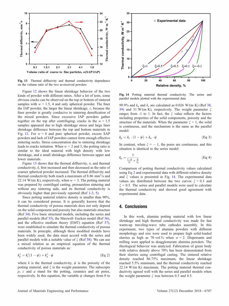
Figure 12 shows the linear shrinkage behavior of the twokinds of powder with different ratios. After a lot of tests, someobvious cracks can be observed on the top or bottom of sinteredsamples with w = 1.5, 4 and only spherical powder. The finerthe IAP powder, the larger the linear shrinkage, e, because thefiner powder is greatly conducive to sintering densification ofthe mixed powders. Since excessive IAP powders gathertogether on the top after centrifuging, cracks in the w = 1.5samples appeared due to high shrinkage stress and large linershrinkage difference between the top and bottom materials inFig. 12. For w = 4 and pure spherical powder, excess SAPpowders and lack of IAP powders cannot form enough effectivesintering necks. Stress concentration due to sintering shrinkageleads to cracks initiation. When w = 2 and 3, the potting ratio issimilar to the ideal material with high density with lowshrinkage, and a small shrinkage difference between upper andlower materials.
Figure 13 shows that the thermal diffusivity, a, and thermalconductivity, k, first increased and then decreased as the ratio ofcoarser spherical powder increased. The thermal diffusivity andthermal conductivity both reach a maximum of 8.86 mm2/s and22.14 W/(m K), respectively, when w = 3. The potting materialwas prepared by centrifugal casting, pressureless sintering andwithout any sintering aids, and its thermal conductivity isobviously higher than previously reported (Ref 1-3, 5).
Since potting material relative density is smaller than 90%,it can be considered porous. It is generally known that thethermal conductivity of porous materials does not only dependon the solid component and porosity but also materials structure(Ref 34). Five basic structural models, including the series andparallel models (Ref 35), the Maxwell–Eucken model (Ref 36),and the effective medium theory (EMT) equation (Ref 37),were established to simulate the thermal conductivity of porousmaterials. In principle, although these modified models havebeen widely used, the data must accord with the series andparallel models with a suitable value of n (Ref 38). We can usea mixed relation as an empirical equation of the thermalconductivity of porous materials as:
knp ¼ knc 1� wð Þ þ kna � w ðEq 2Þ
where k is the thermal conductivity, w is the porosity of thepotting material, and n is the weight parameter. The subscriptsp, c and a stand for the potting, ceramics and air pores,respectively. In this equation, the variable w changes from 0 to
99.9% and ka and kc are calculated as 0.026 W/(m K) (Ref 38,39) and 31 W/(m K), respectively. The weight parameter nranges from -1 to 1. In fact, the n value reflects the factorsincluding properties of the solid components, porosity and thestructure of the materials. When the parameter n = 1, the solidis continuous, and the mechanism is the same as the parallelmodel:
kp ¼ kc � 1� wð Þ þ ka � w ðEq 3Þ
In contrast, when n = � 1, the pores are continuous, and thissituation is identical to the series model:
kp ¼1
1�wkc
þ wka
ðEq 4Þ
Comparison of potting thermal conductivity values calculatedusing Eq 2 and experimental data with different relative densityand n values is presented in Fig. 14. The experimental datavalues are distributed between the two curves n = 0.3 andn = 0.5. The series and parallel models were used to calculatethe thermal conductivity and showed good agreement withexperimental data.
4. Conclusions
In this work, alumina potting material with low linearshrinkage and high thermal conductivity was made for fastwarm-up traveling-wave tube cathodes assembly. In thisexperiment, two types of alumina powders with differentmorphology and size were used to prepare high solid-loadedslurries as high as 70 vol.% when w = 2. Dispersants andmilling were applied to deagglomerate alumina powders. Therheological behavior was analyzed. Fabrication of green bodywith relative density above 70% has been demonstrated fromtheir slurries using centrifugal casting. The sintered relativedensity reached 86.75% maximum, the linear shrinkagereached 5.5% minimum, and the thermal conductivity reached22.14 W/(m K) maximum. The potting material thermal con-ductivity agreed well with the series and parallel models whenthe weight parameter n was between 0.3 and 0.5.
5
6
7
8
9
10
12
14
16
18
20
22
24
The
rmal
diff
usiv
ity, m
m2 /s
Volume ratio of coarse to fine particles, w(SAP:IAP)0:1 1.5:1 2:1 3:1 4:1 1:0
The
rmal
con
duct
ivity
, W·m
-1·K
-1
Fig. 13 Thermal diffusivity and thermal conductivity dependenceon the volume ratio of the two as-received powders
0 20 40 60 80 1000
5
10
15
20
25
30
35
ξ=−0.1ξ=0.1ξ=0.3ξ=0.5
Ther
mal
con
duct
ivity
, W⋅m
-1⋅K
-1
Relative density, %
Experimental data
ξ=1
Fig. 14 Potting material thermal conductivity. The series andparallel models plotted with the experimental data
Journal of Materials Engineering and Performance Volume 27(12) December 2018—6707

Acknowledgments
This work was supported by the State Key Lab of AdvancedMetals and Materials (Grant No. 2018-Z06). AV acknowledgessupport from the National Science Foundation (IRES 1358088).
References
1. D.S. Orlowska, Fast warm cathode—practical fielded design, inNational Vacuum Electronics Conference (Surrey Ion Beam Centre,2007)
2. K.S. Pal, S. Ghosh, N. Dandapat, S. Datta, D. Basu, and R.S. Raju,Development of Suitable Potting Material for Dispenser Cathodes of aHigh Power Microwave Tube,Mater. Sci. Eng. B, 2012, 177(2), p 228–232
3. P. Swartzentruber, M. Collier, R. Dewees, and W. Epperson, Alterna-tive ceramic potting materials for dispenser cathodes, in VacuumElectronics Conference (2012), pp. 483–484
4. C.W. Park and D.Y. Yoon, Effect of SiO2, CaO2 and MgO Addition onthe Grain Growth of Alumina, J. Am. Ceram. Soc., 2000, 83(10), p2605–2609
5. L. Wolverton, J.O. Tarter, R.E. Eitel, and M. Weisenberger, P1–33:Thermal properties of alumina cathode heater potting materials, inVacuum Electronics Conference (IVEC), (2010), p. 165
6. L.R. Falce, Dispenser cathodes: The current state of the technology, inInternational Electron Devices Meeting (1983), pp. 448–451
7. G.L. Messing and G.Y. Onoda, Inhomogeneity-Packing DensityRelations in Binary Powders—Experimental Studies, J. Am. Ceram.Soc., 1978, 61(7–8), p 363–366
8. J.A. Dodds, The Porosity and Contact Points in MulticomponentRandom Sphere Packings Calculated by a Simple Statistical GeometricModel, J. Colloid Interface Sci., 1980, 77(2), p 317–327
9. J. Funk and D. Dinger, Packing of Discrete Versus Continuous ParticleSize Distributions, Interceramic, 1992, 41(5), p 332–334
10. J. Funk and D. Dinger, Fundamentals of Particle Packing, Monodis-perse Spheres, Interceramic, 1992, 41(1), p 10–14
11. J. Funk and D. Dinger, Review of Packing in Polydisperse ParticleSystems, Interceramic, 1992, 41(2), p 95–97
12. J. Funk and D. Dinger, Computer Modelling of Particle PackingPhenomena, Interceramic, 1993, 42(3), p 150–153
13. J. Zheng, W.B. Carlson, and J.S. Reed, The Packing Density of BinaryPowder Mixtures, J. Eur. Ceram. Soc., 1995, 15(5), p 479–483
14. K.R. McGeary, Mechanical Packing of Spherical Particles, J. Am.Ceram. Soc., 1961, 44(10), p 513–522
15. A.B. Yu, N. Standish, and A. Mclean, Porosity Calculation of BinaryMixtures of Nonspherical Particles, J. Am. Ceram. Soc., 1993, 76(11),p 2813–2816
16. P.A. Smith and R.A. Haber, Effect of Particle Packing on the Filtrationand Rheology Behavior of Extended Size Distribution AluminaSuspensions, J. Am. Ceram. Soc., 1995, 78(7), p 1737–1744
17. S. Taruta, N. Takusagawa, K. Okada, N. Otsuka, S. Taruta, N.Takusagawa, K. Okada, and N. Otsuka, Slip Casting of AluminaPowder Mixtures with Bimodal Size Distribution, J. Ceram. Soc. Jpn.,1996, 104(1209), p 447–450
18. G.T. Igrave, J.M.F. Ferreira, A.T. Fonseca, and O. Lyckfeldt, Influenceof Particle Size Distribution on Colloidal Processing of Alumina, J.Eur. Ceram. Soc., 1998, 18(3), p 249–253
19. J.M.F. Ferreira and H.M.M. Diz, Pressure Slip Casting of Bimodal SiliconCarbide Powder Suspensions, Ceram. Int., 1999, 25(6), p 491–495
20. G. Tari, J.M.F. Ferreira, and A.T. Fonseca, Influence of Particle Sizeand Particle Size Distribution On Drying-Shrinkage Behaviour ofAlumina Slip Cast Bodies, Ceram. Int., 1999, 25(6), p 577–580
21. S. Taruta, Y. Sakurai, N. Takusagawa, K. Okada, and N. Otsuka, SlipCasting of Alumina Powder Mixtures with Bimodal Size Distribution:Influence of Particle Size Difference Between Fine and CoarsePowders on Packing and Consolidation Process, J. Ceram. Soc. Jpn.,2000, 108, p 254–260
22. J.U. Chenhui, W. Yanmin, Y.E. Jiandong, L.I. Xinheng, W. Yanmin,Y.E. Jiandong, and L.I. Xinheng, Effect of Particle Size Distribution onthe Rheological Behavior of Dense Alumina Suspensions, J. Chin.Ceram. Soc., 2006, 34(8), p 985–991 (in Chinese)
23. W. Qi, C. Wei, G. Yiyao, and X. Zhipeng, Preparation and SinteringProperties of Alumina Slurries with High Solid Loading, Rare MetalMat. Eng., 2013, 42(S1), p 400–403 (in Chinese)
24. Y. Sun, S. Shimai, X. Peng, M. Dong, H. Kamiya, and S. Wang, AMethod for Gelcasting High-Strength Alumina Ceramics with LowShrinkage, J. Mater. Res., 2014, 29(02), p 247–251
25. A. Heunisch, A. Dellert, and A. Roosen, Effect of Powder, Binder andProcess Parameters on Anisotropic Shrinkage in Tape Cast CeramicProducts, J. Eur. Ceram. Soc., 2010, 30(16), p 3397–3406
26. Z. Fu, P. Polfer, T. Kraft, and A. Roosen, Correlation BetweenAnisotropic Green Microstructure of Spherical-Shaped Alumina Par-ticles and Their Shrinkage Behavior, J. Am. Ceram. Soc., 2015, 98(11),p 3438–3444
27. G. Tarı, J.M.F. Ferreira, A.T. Fonseca, and O. Lyckfeldt, Influence ofParticle Size Distribution on Colloidal Processing of Alumina, J. Eur.Ceram. Soc., 1998, 18(3), p 249–253
28. A. Tsetsekou, C. Agrafiotis, and A. Milias, Optimization of theRheological Properties of Alumina Slurries for Ceramic ProcessingApplications Part I: Slip-Casting, J. Eur. Ceram. Soc., 2001, 21(3), p363–373
29. R.G. Horn, Surface Forces and Their Action in Ceramic Materials, J.Am. Ceram. Soc., 1990, 73(5), p 1117–1135
30. C.J. Brinker and G.W. Scherer, Sol–Gel Science, Academic press,Boston, 1990
31. S.J. Schneider, Engineered Materials Handbook, ASM International,Geauga, 1991
32. E. Carlstrom, Surface and Colloid Chemistry in Ceramics: AnOverview, Marcel Dekker, New York, 1994
33. R. Moreno, The Role of Slip Additives in Tape Casting Technology 2.Binders and Plasticizers, Am. Ceram. Soc. Bull., 1992, 71(11), p 1647
34. L. Miettinen, P. Kekalainen, T. Turpeinen, J. Hyvaluoma, J. Merikoski,and J. Timonen, Dependence of Thermal Conductivity on StructuralParameters in Porous Samples, AIP Adv., 2012, 2(1), p 2150–2240
35. A.G. Leach, The Thermal Conductivity of Foams. I. Models for HeatConduction, J. Phys. D Appl. Phys., 1999, 26(5), p 733
36. Z. Hashin and S. Shtrikman, AVariational Approach to the THEory ofThe Effective Magnetic Permeability of Multiphase Materials, J. Appl.Phys., 1962, 33(10), p 3125–3131
37. R. Landauer, The Electrical Resistance of Binary Metallic Mixtures, J.Appl. Phys., 1952, 23(7), p 779–784
38. L. Gong, Y. Wang, X. Cheng, R. Zhang, and H. Zhang, A NovelEffective Medium Theory for Modelling the Thermal Conductivity ofPorous Materials, Int. J. Heat Mass Transfer, 2014, 68(1), p 295–298
39. H. Shenker, J.I. Lauritzen, R.J. Corruccini, and S.T. Lonberger,Reference Tables for Thermocouples, 564 (1955)
6708—Volume 27(12) December 2018 Journal of Materials Engineering and Performance