the international journal of robotics research...
TRANSCRIPT

http://ijr.sagepub.com/Robotics Research
The International Journal of
http://ijr.sagepub.com/content/17/6/667The online version of this article can be found at:
DOI: 10.1177/027836499801700606
1998 17: 667The International Journal of Robotics ResearchChristopher J. Damaren
Modal Properties and Control System Design for Two-Link Flexible Manipulators
Published by:
http://www.sagepublications.com
On behalf of:
Multimedia Archives
can be found at:The International Journal of Robotics ResearchAdditional services and information for
http://ijr.sagepub.com/cgi/alertsEmail Alerts:
http://ijr.sagepub.com/subscriptionsSubscriptions:
http://www.sagepub.com/journalsReprints.navReprints:
http://www.sagepub.com/journalsPermissions.navPermissions:
http://ijr.sagepub.com/content/17/6/667.refs.htmlCitations:
What is This?
- Jun 1, 1998Version of Record >>
at RYERSON UNIV on June 24, 2014ijr.sagepub.comDownloaded from at RYERSON UNIV on June 24, 2014ijr.sagepub.comDownloaded from

667
Modal Properties andControl System Designfor Two-Link Flexible
Manipulators
Christopher J. DamarenDepartment of Mechanical EngineeringUniversity of CanterburyChristchurch, New Zealand
Abstract
The vibration modes of a generic two-link fiexible manipulator arestudied as a function of the link, rotor, and tip (statorlpayload)mass distribution. Necessary and sufficient conditions are devel-
oped for all vibration modes to exhibit a node at the manipulatorendpoint. A rigorous treatment of the relevant kinematics and dy-namics shows that this property can be closely achieved for largetip/link mass ratio and sufficiently small rotor inertia. The majorimpacts of this result on feedforward/feedback controller design areuncovered. First, the nonlinear joint torque to end-effector motiondynamics become essentially equivalent to those of the rigid case.Second, an output involving the endpoint rates and elastic motionsis shown to possess the passivity property for suitably defined inputs.This permits the design of simple controllers that furnish endpointstabilization with simultaneous vibration suppression. A numeri-cal example is used to illustrate the results and demonstrate theachievable performance using the controller design concepts.
1. Introduction
The impact of structural flexibility on the analysis and controlof lightweight robots presents a serious challenge to roboticengineers. However, this marriage of structural dynamics,nonlinear multibody dynamics, and a difficult control prob-lem exhibiting sensor/actuator noncollocation has providedan irresistible allure for many researchers. The literature ofthe field continues to grow, and recent overviews of the prob-lem are provided by Book (1993a, 1993b) and Canudas deWit, Siciliano, and Bastin (1996).
The basic problem of controlling the endpoint motion us-ing joint-based actuation can be divided into feedforward andfeedback design, both of which are greatly complicated bythe noncollocated nature of the relevant output. It is well
known that the inverse dynamics problem typically leads tononcausal solutions (Bayo et al. 1989), and the relevant input-output map used in feedback design is nonminimum phase
The International Journal of Robotics Research,Vol. 17, No. 6, June 1998, pp. 667-678,@ 1998 Sage Publications, Inc.
(De Luca, Lucibello, and Ulivi 1989). However, the torqueto joint rate dynamics retain the favorable passivity propertyof the rigid situation. This key property is characteristic ofsystems with collocated dual actuation and sensing and un-derlies many of the known results for control of rigid robots(Canudas de Wit, Siciliano, and Bastin 1996). In this light, ithas been suggested by De Luca and Siciliano (1993) that theendpoint problem be addressed indirectly using joint-basedtechniques that seek tracking of prescribed joint-space tra-jectories. An interesting compromise approach by Padenet al. (1993) used a causal approximation for the endpointinverse dynamics solution in conjunction with a passive joint-based feedback.
Given the desirability of the minimum phase property orthe stronger passivity property, several researchers have par-ticipated in the hunt for modified inputs and/or outputs thatyield these properties. The reflected tip position was intro-duced by Wang and Vidyasagar (1990, 1992) for a singleflexible link, and its rate was shown to yield a passivity prop-erty by Pota and Vidyasagar (1991). De Luca, Lucibello,and Ulivi (1989) showed that by using a suitable point alonga single link as the output, minimum phase behavior couldbe obtained. Yim (1993) showed that this idea could workfor a spatial three-link arm in which the last link is flexible.Barbieri (1993) analyzed the properties of transfer functionsfor various outputs in the single-link case. The possibilityof transmitting the input torque to another location along abeam has been considered by Park and Asada (1994).Among the reasons for designing a flexible robot arm are
the desire for increased speed of operation, reduced robotmass as in space operations, and increased payload capabil-ity. The asymptotic situation of a large payload/robot massratio has been addressed by Damaren (1995), in which itwas shown that the modified output idea could be used toobtain passivity for a general multilink flexible robot. Thisemanates from the clamped nature of the vibration modesat the manipulator end-effector. It was shown in Damaren
(1996b) that feedforward design was possible that preservedthe passivity property in the error dynamics, which openedthe door to an adaptive approach (Damaren 1996a). These
at RYERSON UNIV on June 24, 2014ijr.sagepub.comDownloaded from

668
analyses naturally lead to consideration of other systems thatmay enjoy similar properties.
In the present paper, we address planar two-link flexiblemanipulators and illustrate how the mass distribution in thelinks, joint stators, joint rotors, and payload affect the input-output map. The control problem for such a system was firstaddressed by Book, Maizza-Neto, and Whitney (1975) usingclassical approaches. Our key result shows that when thetip mass of each link is much greater than that of the linkmass, certain modal properties greatly simplify feedforwardand feedback design. Although the system is nonlinear, ourphilosophy is to examine the vibration modes for a genericconfiguration and infer potential control schemes for the ac-tual system. This modal approach is later justified using anonlinear model, and our numerical results indicate that goodperformance can be achieved using the proposed controllers.
Although the two-link scenario may seem unduly restric-tive, it is a significant step forward from previous worksthat have emphasized either one-link or systems with oneflexible link. Furthermore, many experimental systems thathave been designed to study the efficacy of various controlschemes fall into the two-link category. Our results may aid ininterpreting the results produced by these facilities, many ofwhich are constructed with flimsy links so as to be mass dom-inated by the motors and payload. In fact, the results of thispaper were inspired by the initial examination by Damaren,Stanway, and Sharf (1995) of the modal properties of sucha facility developed at the University of Victoria. Finally,insightful analytical progress and literal results are possiblein the two-link case.
2. Motion Equations and Modal AnalysisThe motion equation for flexible-link robots (omitting struc-tural damping) can be written as
where M, K, and T are the mass matrix, stiffness matrix,and joint torques, respectively. The nonlinear inertial forcesfno,.,, are quadratic in q. The generalized coordinates arepartitioned as q = collo, qe}, where 0(t) are the N jointangles and qe(t) are the Ne elastic coordinates. The latterare generated using clamped-free modeling for the elasticdeflections of each link. Hence, the above matrices can be
partitioned consistent with q:
with M = MT > 0 and Kee = K e > O.The kinematics describing the Cartesian end-effector dis-
placements p(t) can be summarized by the forward kinemat-ics map p = ~(9, qe), with p = Je(0, qe)b + Je(0, qe)qe;
Je and Je are Jacobian matrices. For the planar two-link ma-nipulators considered here, p = [x y]T, where and y arein-plane translations. A more general output known as thep-tip rate has been defined by Damaren (1995):
where p = 1 captures the true tip rates and p = 0 constitutesan output involving only joint motions. For the durationof this paper, it is assumed that Jo is square and invertible.Given this assumption, a more useful control input for our
purposes is u(t) = 0Consider small excursions of the coordinates Jq in the
vicinity of a constant configuration q = col~6, 0}. The lin-earized forms of eqs. (1) and (3) are
where the input and output matrices are B(q) = [Je O]Tand C(q) = [Je ~.GJeI~ respectively. The eigenproblem cor-responding to (4) can be written as
where wa are the unconstrained (joints unlocked) vibrationfrequencies and qa = col{80:, qea}, cx = 1 - Ne, are theeigenvectors (mode shapes). Note that 80: are the modeslopes at each joint axis. The term unconstrained is justifiedbecause each &dquo;clamped&dquo; link is embedded within a freely ro-tating frame. For a single-link system, the results of (5) wouldbe the pinned-free modes whose motion (qa cos cvat) is com-posed of the clamped-free link deflections (qea coswo:t) su-perimposed on the joint motion (0a cos wat). In general,unconstrained modes are configuration dependent, whereasthe constrained basis used for each link is not. This, coupledwith the simple structure of the input matrix in (1) and (4),forms most of the motivation for this modeling approach.Assuming N joints, there are also N zero-frequency rigid
modes collectively of the form Qr = [1 O]T. The modesenjoy standard orthonormality relations with respect to Mand K:
Expanding the solution of eq. (4) in terms of eigenvectors6q(t) = Qrl1r(t) + ~a 9arla(t)~ it is relatively straightfor-ward to obtain the modal equations
at RYERSON UNIV on June 24, 2014ijr.sagepub.comDownloaded from

669
Using Laplace transforms, the dynamics of the linearizedsystem can be captured by the input-output description
Many important properties of this system are governed bythe relationship between ba and Ca.
Recall that a general square system is passive if
JoT yT u dt > 0, VT > 0, and Vu such that f T uT u dt < oo.
For linear time-invariant systems, this is equivalent to pos-itive realness of the corresponding transfer function G(s);that is, G(s) is analytic, and G(s) + GH(s) > 0 for s in the
open right-half plane. The major significance of the passiv-ity property is the closed-loop stabilization predicted by thepassivity theorem (Desoer and Vidyasagar 1975); that is, astrictly passive controller such as a PI law (a PD law appliedto position) will stabilize a passive plant.
Following Newcomb (1966) and Anderson and Vongpan-itlerd (1973), a transfer matrix of the form G(s) in (11) ispositive real if and only if cab; > 0, since the coefficientof s-1 is nonnegative definite. The easiest way for this tohappen is can = ba, which is ensured when C = BT; that is,collocation of actuation and rate sensing. Among the first torecognize the relative ease with which such a system could bestabilized was Gevarter (1970), who showed by using pertur-bation arguments that small proportional and derivative gainswere stabilizing in the collocated case. A specific instanceof this occurs when it = 0, which implies that y = Jo8 andba = c. = J000.An important question then arises: Is collocation the only
mechanism by which c«ba > O? In the SISO case, this is
somewhat easier to achieve, since eaba > 0 only requiresthat ea and b« have the same sign. In general, for It ~ 0,the vectors b« and co will not resemble each other, which re-flects noncollocation of the joint actuation and end-effectorrate sensing. In Damaren (1995), it was shown that if a
nonredundant flexible manipulator carries a payload muchmore massive than the arm, then Je00 + Jeqea * 0; thatis, the mode shapes are approximately clamped at the end-effector. In this case, the input-output map from torquesto end-effector rates becomes essentially rigid, since thevibration modes become unobservable from the tip. This
follows from c« = 0 in (11). Furthermore, for general M,cab; ~ (1 - tc)(Jee«)(Jee«)T ~ which is nonnegative def-inite if /~ < 1, thus rendering the transfer matrix in (11)positive real. Other ramifications of this property will bediscussed in Section 5.
In the interest of finding other situations in which this keyproperty holds, we note the following result.
LEMMA 1. The mode shapes, qa, of (5) satisfy Je9a+Jeqea = 0, a = 1 - &dquo; Ne, if and only if MBeJe 1Je = Mee.Proof. Using the eigenequation (5) and the partitioning ofthe mass and stiffness matrices in (2), the eigencolumns sat-isfy Mee9a + Meeqea = 0. Thus,
Clearly, we have sufficiency. Suppose Jø8a + Je<teo: = 0.Since Ne qe« are linearly independent, the null space of theN x Ne matrix (MeeJe 1 Je - Mee ) must have dimension Ne ;hence, MeeJe 1Je - Mee = O. D
In the next section, the existence of this property for planartwo-link manipulators will be addressed. Note that this nec-essary and sufficient condition is independent of the stiffnessproperties.
3. Main Results: Two-Link Flexible Manipula-tors
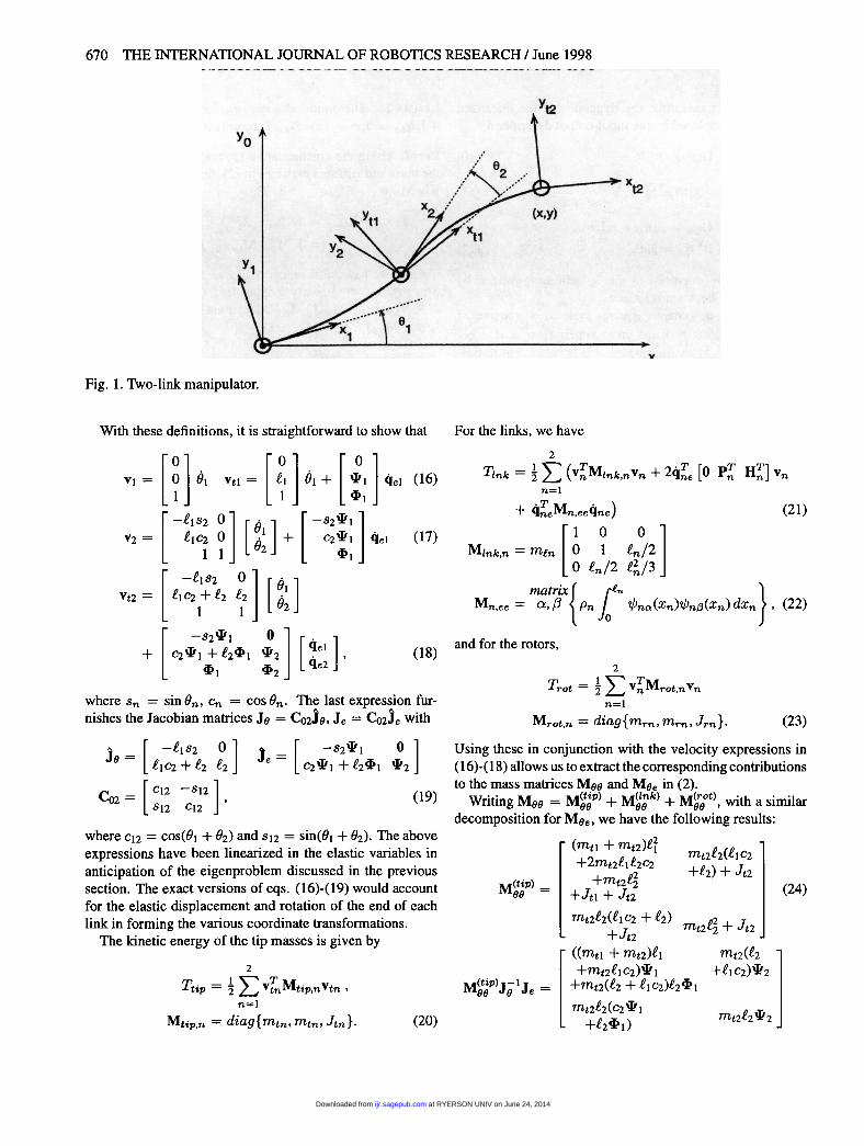
Consider the arm in Figure 1. Let min and in denote themass and length of the uniform elastic link and define Pn =
me~,/.~n, n = 1, 2. At the end of each link is a tip mass withmass mtn and inertia Jtn. At each joint is a rotor with massmrn and inertia Jrn.
Denote the reference frames in Figure 1 by Xn and -Ftn,n = 1, 2, and let Vn = [Vn., vny úJnz]T denote the gener-alized velocity of Y,,; that is, Vnx and vny are the absolutevelocity components of Yn expressed in Xn, and wnz is theabsolute angular velocity. The velocity Of-Ftn, vtn is definedsimilarly. The transverse elastic deformation of each link isdesignated u~,e(~n, t) and expressed as
where the ’l/Jn(3 are cantilevered shape functions. We definethe following matrix quantities:
Also,
where
and
are the momentum coefficients.
at RYERSON UNIV on June 24, 2014ijr.sagepub.comDownloaded from
670
Fig. 1. Two-link manipulator.
With these definitions, it is straightforward to show that For the links, we have
where sn = sin On, en = cos 0n. The last expression fur-nishes the Jacobian matrices Je = Co2Je, Je = Co2Je with
where C12 = COS(OL + 02) and S12 = sin(Ol + 92). The aboveexpressions have been linearized in the elastic variables inanticipation of the eigenproblem discussed in the previoussection. The exact versions of eqs. ( 16)-( 19) would accountfor the elastic displacement and rotation of the end of eachlink in forming the various coordinate transformations.The kinetic energy of the tip masses is given by
and for the rotors,
Using these in conjunction with the velocity expressions in( 16)-( 18) allows us to extract the corresponding contributionsto the mass matrices Mee and Mee in (2).
Writing Mee = Meep~ + Mee k~ + Mee t>> with a similar
decomposition for Mee, we have the following results:
at RYERSON UNIV on June 24, 2014ijr.sagepub.comDownloaded from

671
Some general comments regarding these expressions arein order. First, when Jtl = Jt2 = 0, the tip quantities givenby (25) and (26) produce the momentum balance requiredin Lemma 1. When Jtn # 0, these expressions are equal ifwn = £n4ln. Second, the link quantities in (28) and (29)are also equal if 2Pn = mln wn and 3Hn = mlnfn wn.These conditions will not be satisfied in general. For ex-
ample, for the first cantilevered-free mode shape of a uni-form beam, ~~,1 = 0.726en9~,l, 2.56P., *= 7T~~, and3.52~t = mlnfnt/JnI. However, there is one important sit-uation addressed below in Lemma 2 in which they do hold.In general, the rotor terms in (31) and (32) do not constitutethe required balance. As expected, the contributions of mr2
mirror those of mtl, and it will be assumed that they havebeen incorporated into the latter.
LEMMA 2. Assume that Jri = Jr2 = 0, and that each linkis modeled by a single linear shape function ybni = Cn~~,,where Cn is a normalization constant. Then,
for all mtn > 0, min > 0, Jtn > 0, and 62 E (0,7r).Proof. Since iPn = ybni(£n) = Cn.en, we have 4ln =Cn = en 1 ~n, Pn = (m~/2)~~,andH~ = (m~~/3)~.Hence, on the basis of (25)-(29), (Mee~~ + M~;k»J8-IJe =Oe + Oe from which the result follows usingLemma 1. 0
Note that this situation corresponds precisely to a flexible-joint robot with lumped torsional stiffnesses at the link rootsand rotors of vanishingly small moment of inertia. Next,we examine the situation for a more realistic discretization
strategy.
DEFINITION 1.
where II( ’)11 denotes the Euclidean norm.
THEOREM 1. Let mtI/mt2 = Ce, ?Ttti/?7~2 = Ct and f2 =m12 /mt2 , and assume that Jtn = Jrn = 0, n = 1, 2. Then ,Ja is 0(€2), a = 1... Ne, for Õ2 e (0,7r).Proof. Begin by nondimensionalizing modal quantities asfollows: 4tn = QiPn, liin = 4lnfl%/£n, Pn =( men -lPn, fin = ( m~n.~n)-lHn. Using the expres-sions in (25)-(29),
Noting that pa = J9M;J(M99J;I 1Je -Mee)9ea and writingMee = rntzlMee~~~ we have
at RYERSON UNIV on June 24, 2014ijr.sagepub.comDownloaded from

672
Here, &(.) denotes the largest singular value. Given the nor-malization for qa in (6), 11 q,,,, 112 < IIqall2 ~ !B-I(M), where~(~) is the smallest eigenvalue; hence, p,,, ~ 0 as E2 ~ 0,and the endpoint of the manipulator becomes a node for eachvibration mode. Considering that C~p~ = Je9«-~Jeqe« ~0 as well, (19) yields -s2(.~191« + ‘~Iqle,«) ~ 0, and theendpoint of the first link also becomes a node for s2 ~ 0. Weconclude that the asymptotic behavior of each vibration modecorresponds to pinned-pinned motion for each link, and henceq,, is independent of mt2 ; that is, e2. Furthermore, 9« ~ 0,and Møeqea = - MøøO a 1= O.
Consider the denominator of J« in (33). As E2 - 0,
Hence, in the limit,
where g(~) is the least singular value. Combining this with
(34) and noting the definition (33) gives
where C is independent of E2. This follows from the fact thatql e,a and q2e,« tend toward the &dquo;elastic part&dquo; of the pinned-pinned vibration mode and that the ratio of norms involvingqea is independent of normalization. 0
Although the above result neglects the self-inertia of tipbodies and inboard rotors, the effect of the latter is somewhat
mitigated. The discrepancies between (31) and (32) are ofthe form Jrn.~~ 1 ~n , and therefore the first-order impact onPa is terms containing wnqne,a. Given the pinned-pinnedbehavior of the modes discovered above, the first-order effectof Jrn is zero as E2 -~ 0. It is worth mentioning that noneof the results given above relies on the elastic properties ofthe link, only on the interplay between kinematics and massproperties.The reader may naturally wonder what happens beyond
two links in the planar case. Consider the addition of a thirdlink with corresponding properties m13, ~3, mt3, Jt3, mr3,and augmentation of p with the rotation of Yt3 with respect
to Xo ; that is, p = [x y O]T . The Jacobians correspondingto (19) are
Calculations analogous to (25) and (26) show that the re-quired balance is now achieved for mt, and mt2 if ~3 =£3<1-3. · This is trivially accomplished if the third link isrigid. The balance occurs for Jtl and Jt2 if ~~, _ .~n~~,,n = 1,2,3. Lemma 2 generalizes to the three-link case,since with ~~.1 = zn and Jrn = 0, n = 1, 2, 3, jo = Je andMoo = Mee.
For mt3 and Jt3, the balance always occurs, since
the contributions to M~ and M~~ are j§Mtjp 3je and-T -
’
Je M~p,3Je, respectively, where Mhp,3 is generated accord-ing to (20). This is expected given the large payload results ofDamaren (1995). Furthermore, Jt3 pervades all nine entriesof the matrices M~;p) and M~;P)JÕI Je. With these observa-tions, we permit the following extension of Theorem 1 fora planar three-link flexible manipulator with the third linkrigid: if Jri = Jr2 = 0, then Ja - 0, a = 1&dquo; - Ne, asmin /mtn - 0 and Jtn/Jt3 -~ 0, n = 1, 2. Here, Ja is thethree-dimensional version of (33), and we assume as beforethat det Je ~ 0. Unlike the two-link case, the tip inertiasof links 1 and 2 need now only be small compared to thepayload inertia Jt3.
4. Control System DesignThe nonlinear consequences of the property MeeJe 1Je e =
Mee are easily deduced. Letting 9 = Je 1(p - Jeqe), thekinetic energy T = 14T 2 M4 decouples into T = Tp + Te,where
Since the potential energy is Ve = 2 qe Kee9e ~ and the vir-tual work is 8We = TT b9 = uT (8p - Je8qe), Lagrange’sequations yield
at RYERSON UNIV on June 24, 2014ijr.sagepub.comDownloaded from

673
which are coupled by virtue of the configuration dependenceof Mpp, Mee, Je, and Je.
Although the mass matrices Mpp and Mee depend on 0and qe, a suitable approximation is to neglect the elastic co-ordinate dependence and take 0 = .~r 1 (p), where F, (.) isthe rigid forward kinematics map. If one further neglects theO<l!qe 112) term in (36), it becomes equivalent to the rigid-body task-space motion equations relating u to p. On thisbasis, the rigid inverse dynamics strategy corresponding to aprescribed trajectory Pd should produce good endpoint track-ing that is consistent with the linear relations in (10)-(12)when p = 1. The separation of endpoint and elastic dynam-ics is reminiscent of the singular perturbation approach ofSiciliano and Book (1988). In their work, the elastic equa-tions played the role of &dquo;fast dynamics&dquo; and were similarto (37). However, the analogue of (36) was the joint-spacedynamics of the equivalent rigid arm. The assumption oflarge stiffness led to approximate decoupling, whereas herethe decoupling is made possible by relative mass propertiesindependent of the stiffness.
Definining the Hamiltonian H = Tp + Te + ~ and us-ing standard properties of Euler-Lagrange systems (van derSchaft 1996), we have the energy balancer = uT(p-Je9e).The approximate form of (36) defined above implies thatTp = u~p, and hence Te + 1e = -u Je4e. Since
p~ = p - (1- ¡.t)Je4e, we have Tp + (1- ¡.t)(Te + Ve) = p§uor, upon integration,
which yields passivity of the mapping from u to p~ whentt < 1. For IL = 1, we have passivity but lose observabilityof the elastic coordinates.
Given the passivity result for it < 1, many controllerscan be constructed that yield setpoint regulation for the end-effector coordinates. In particular, a PD law of the formT = 0 [Kdi), + Kp(p~ - Pd)] with Kp = Kp > 0 and
Kd = KT > 0 can be expected to yield p(t) -~ pd andqe(t) --> 0 as t ~ oo. However, to guarantee this result inthe absence of controllability/observability assumptions forqe, a small damping term of the form Deeqe is required on theleft-hand side of (37). The Lyapunov function V = Tp + (1 I- A)(T- + Ve) -f- i(p~ - pd)T Kp(p~ - Pd) , in conjunctionwith the damped form of (38), yields V = ―p~K~p~ -e _4,. Hence, as t -> oo, qe(t) --> 0, p~(t) - 0, andp(t) = p~ + (1 - /-I)Je4e , 0. LaSalle’s theorem with
(36) and (37) gives the desired result. The robustness of thisstabilization result hinges only on the property in Lemma 1that has been shown to hold asymptotically for large tip/linkmass ratio. Tracking of a time-varying trajectory Pd(t) canbe accomplished by suitably modifying a feedforward basedon (36) and (37) to preserve passivity in the error dynamics(Damaren 1996b).
Fig. 2. Ja versus 77~/77~.
5. Numerical ExampleConsider the flexible manipulator of Figure 1 with the follow-ing link properties: in = t = 0.5 m, Mfn = me = 0.1 kg,and (EI)n = 1 N-m , n = 1, 2. We set Jtn = Jt, Jrn = Jr,mtn = mt and initially take Jt = Jr = 0 with 62 = -7r/2.For spatial discretization, the exact cantilevered-free modeshapes of a uniform beam will be used with two per link.The global mass and stiffness matrices can then be formedand used to solve the eigenproblem in (5). With qa in hand,Ja in (33) can be formed using the Jacobian matrices in (19).
In Figure 2, the values of Ja for the four unconstrainedvibration modes are shown as a function of the mass ratio
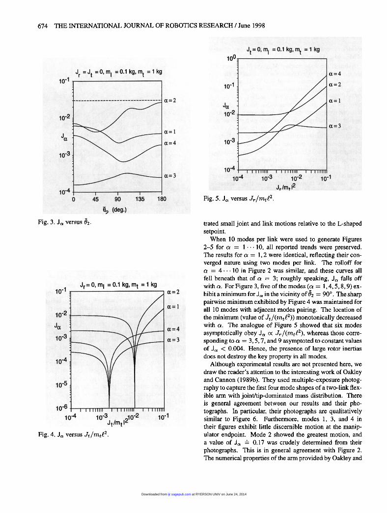
mt/mt. The asymptotic behavior is in agreement with The-orem 1, and for 77~/77~ > 10, we have Ja < 0.01. In Figure3, the configuration dependence of Ja on 62 is shown for thefixed ratio mt!mt = 10. For all configurations, Ja < 0.03.The effect of tip inertia is portrayed in Figure 4 using the
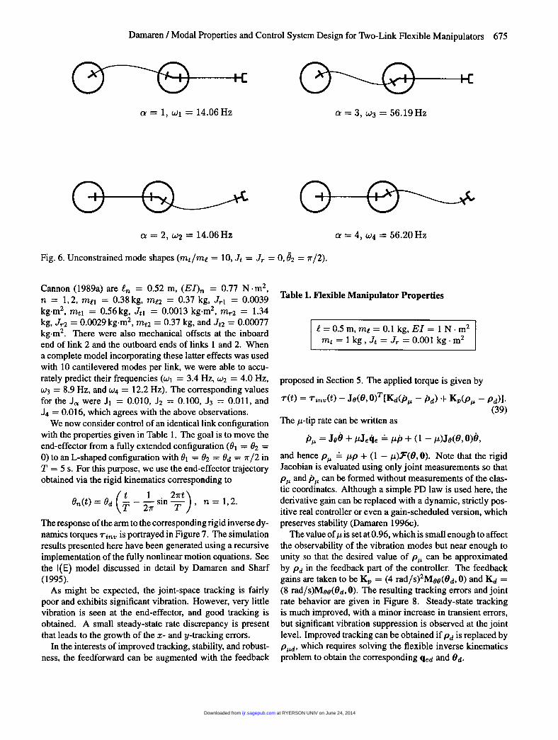
same parameter datum. Note that critical values of Jt forceJa = 0, and asymptotically, J3 and J4 remain small. Figure5 shows the variation with rotor inertia that asymptoticallydestroys the momentum balance required to keep Ja small;however, as predicted, the first-order effect is zero. The vi-bration modes are shown in Figure 6, where the number ofcantilevered shape functions has been increased to 10 per linkto improve the accuracy. The most obvious feature is con-finement of vibrations to a single link. Convergence to theexpected pinned-pinned behavior in each link is in evidence,and the numerical frequencies agree quite well with the exactresults for a uniform pinned-pinned beam: WI,2 = 14.05 Hzand cv3,4 = 56.20 Hz. Note that in Figure 6, we have illus-
at RYERSON UNIV on June 24, 2014ijr.sagepub.comDownloaded from
674
Fig. 3. J a versus 02.
Fig. 4. Ja versus Jt/mtl2.
Fig. 5. Ja versus j,/Mtt2.
trated small joint and link motions relative to the L-shapedsetpoint.When 10 modes per link were used to generate Figures
2-5 for a = 1 -&dquo; 10, all reported trends were preserved.The results for a = 1, 2 were identical, reflecting their con-verged nature using two modes per link. The rolloff fora = 4 ... 10 in Figure 2 was similar, and these curves allfell beneath that of a = 3; roughly speaking, Ja falls offwith a. For Figure 3, five of the modes (cx = 1, 4, 5, 8, 9) ex-hibit a minimum for Ja in the vicinity of 62 = 90’. The sharppairwise minimum exhibited by Figure 4 was maintained forall 10 modes with adjacent modes pairing. The location ofthe minimum (value of Jtf(mtf2» monotonically decreasedwith a. The analogue of Figure 5 showed that six modesasymptotically obey Ja « J,./(mt.~2), whereas those corre-sponding to a = 3, 5, 7, and 9 asymptoted to constant valuesof Ja < 0.004. Hence, the presence of large rotor inertiasdoes not destroy the key property in all modes.
Although experimental results are not presented here, wedraw the reader’s attention to the interesting work of Oakleyand Cannon (1989b). They used multiple-exposure photog-raphy to capture the first four mode shapes of a two-link flex-ible arm with joint/tip-dominated mass distribution. Thereis general agreement between our results and their pho-tographs. In particular, their photographs are qualitativelysimilar to Figure 6. Furthermore, modes 1, 3, and 4 intheir figures exhibit little discernible motion at the manip-ulator endpoint. Mode 2 showed the greatest motion, anda value of Ja = 0.17 was crudely determined from theirphotographs. This is in general agreement with Figure 2.The numerical properties of the arm provided by Oakley and
at RYERSON UNIV on June 24, 2014ijr.sagepub.comDownloaded from
675
Fig. 6. Unconstrained mode shapes (mt/me = 10, Jt = Jr = 0, 62 = 7r /2).
Cannon (1989a) are in = 0.52 m, (EI)n = 0.77 N ~ m2,n = 1, 2, me, = 0.38 kg, m12 = 0.37 kg, Jrl = 0.0039kg.m 2, mtI = 0.56kg, Jtl = 0.0013 kg.m2, mr2 = 1.34kg, J,.2 = 0.0029kg m~, mt2 = 0.37 kg, and Jt2 = 0.00077kg.m 2. There were also mechanical offsets at the inboardend of link 2 and the outboard ends of links 1 and 2. Whena complete model incorporating these latter effects was usedwith 10 cantilevered modes per link, we were able to accu-rately predict their frequencies (WI = 3.4 Hz, w2 = 4.0 Hz,c.~3 = 8.9 Hz, and w4 = 12.2 Hz). The corresponding valuesfor the J a were J = 0.010, J2 = 0.100, J3 = 0.011, andJ4 = 0.016, which agrees with the above observations.We now consider control of an identical link configuration
with the properties given in Table 1. The goal is to move theend-effector from a fully extended configuration (01 = 02 =0) to an L-shaped configuration with 91 = 92 = 0d = ~/2 inT = 5 s. For this purpose, we use the end-effector trajectoryobtained via the rigid kinematics corresponding to
The response of the arm to the corresponding rigid inverse dy-namics torques -r,,,, is portrayed in Figure 7. The simulationresults presented here have been generated using a recursiveimplementation of the fully nonlinear motion equations. Seethe I ( E) model discussed in detail by Damaren and Sharf(1995).As might be expected, the joint-space tracking is fairly
poor and exhibits significant vibration. However, very littlevibration is seen at the end-effector, and good tracking isobtained. A small steady-state rate discrepancy is presentthat leads to the growth of the ~- and y-tracking errors.
In the interests of improved tracking, stability, and robust-ness, the feedforward can be augmented with the feedback
Table 1. Flexible Manipulator Properties
proposed in Section 5. The applied torque is given by
The p-tip rate can be written as
and hence p~ _ pp + (1 - p).~’(9, 0). Note that the rigidJacobian is evaluated using only joint measurements so thatp~ and p~ can be formed without measurements of the elas-tic coordinates. Although a simple PD law is used here, thederivative gain can be replaced with a dynamic, strictly pos-itive real controller or even a gain-scheduled version, whichpreserves stability (Damaren 1996c).The value of p is set at 0.96, which is small enough to affect
the observability of the vibration modes but near enough tounity so that the desired value of p~ can be approximatedby Pd in the feedback part of the controller. The feedbackgains are taken to be Kp = (4 rad/s)~M~(0d. 0) and Kd =(8 rad/s)Møø(8d,0). The resulting tracking errors and jointrate behavior are given in Figure 8. Steady-state trackingis much improved, with a minor increase in transient errors,but significant vibration suppression is observed at the jointlevel. Improved tracking can be obtained if pd is replaced byP,,d, which requires solving the flexible inverse kinematicsproblem to obtain the corresponding qed and 9d.
at RYERSON UNIV on June 24, 2014ijr.sagepub.comDownloaded from

676
Fig. 7. Response to rigid inverse dynamics.
at RYERSON UNIV on June 24, 2014ijr.sagepub.comDownloaded from

677
Fig. 8. Responses for rigid feedforward/p-tip PD feedback.
6. Conclusions
A necessary and sufficient condition for the vibration modesof a serial flexible manipulator to exhibit a node at the end-effector has been presented. An explicit treatment of thetwo-link case has shown that this condition is nearly achievedfor large tip/link mass ratio, and the effect of the other para-meters was determined. The ensuing simplified behavior ofthe torque to endpoint dynamics was demonstrated using non-linear arguments and illustrated with a numerical example.In particular, a rigid inverse dynamics strategy was shown toinvert this mapping quite well. Hence, the well-known non-minimum phase behavior of the mapping is largely mitigatedin this asymptotic case.The results also permitted the synthesis of an output con-
taining contributions from the end-effector coordinates andthe elastic motion of the robot. This output possesses the pas-sivity property that permits simultaneous endpoint trackingand vibration suppression to be handled in a simple robustmanner. Although endpoint measurements are required, theproposed output dispenses with the need to measure the elas-tic coordinates and their rates.The raison d’etre of structurally flexible robots lies in in-
creased payload/robot mass capability and increased speed
of operation. This leads to minimization of link mass cou-pled with inherent limitations on possible mass reduction ofthe electromagnetic actuators. The importance of our resultslies in the closeness with which they mirror this situation.
AcknowledgmentThe author gratefully acknowledges financial support pro-vided by the University of Canterbury in the form of ResearchGrant 2201999.
References
Anderson, B.D.O., and Vongpanitlerd, S. 1973. Network
Analysis and Synthesis. Englewood Cliffs, NJ: PrenticeHall.
Barbieri, E. 1993. Single-input/single-output transfer func-tions for a flexible slewing link. J. Robotic Sys. 10(7) :913-929.
Bayo, E., Papadopoulos, P., Stubbe, J., and Serna, M. 1989.Inverse dynamics and kinematics of multi-link elasticrobots: An iterative frequency domain approach. Int. J.Robotics Research 8(6):49-62.
at RYERSON UNIV on June 24, 2014ijr.sagepub.comDownloaded from

678
Book, W. J. 1993a. Controlled motion in an elastic world.ASME J. Dyn. Sys. Meas. Control 115:252-261.
Book, W. J. 1993b. Structural flexibility of motion systemsin the space environment. IEEE Trans. Robotics and Au-tomation 9(5):524-530.
Book, W. J., Maizza-Neto, O., and Whitney, D. E. 1975.Feedback control of two beam, two joint systems withdistributed flexiblity. ASME J. Dyn. Sys. Meas. Control97G(4):424-431.
Canudas de Wit, C., Siciliano, B., and Bastin, G., eds. 1996.Theory of Robot Control. London: Springer-Verlag.
Damaren, C. J. 1995. Passivity analysis for flexible multi-link space manipulators. AIAA J. Guidance, Control, andDynamics 18(2):272-279.
Damaren, C. J. 1996a. Adaptive control of flexible manip-ulators carrying large uncertain payloads. J. Robotic Sys.13(4):219-228.
Damaren, C. J. 1996b. Approximate inverse dynamics andpassive feedback for flexible manipulators with large pay-loads. IEEE Trans. Robotics and Automation 12(1):131-138.
Damaren, C. J. 1996c. Gain scheduled SPR controllers fornonlinear flexible systems. ASME J. Dyn. Sys. Meas. Con-trol 118(4):698-703.
Damaren, C. J., and Sharf, I.1995. Simulation of flexible-link
manipulators with inertial and geometric nonlinearities.ASME J. Dyn. Sys. Meas. Control 117(1):74-87.
Damaren, C., Stanway, J., and Sharf, I. 1995 (May 1989,Victoria, Canada). Modal analysis for an experimentalflexible manipulator. Proc. 15th Canadian Congress onApplied Mechanics. Victoria, British Columbia: Univer-sity of Victoria, vol. 2, pp. 806-807.
De Luca, A., Lucibello, P., and Ulivi, G. 1989. Inversion
techniques for trajectory control of flexible robot arms. J.Robotic Sys. 6(4):325-344.
De Luca, A., and Siciliano, B. 1993. Inversion-based non-linear control of robot arms with flexible links. AIAA J.
Guidance, Control, and Dynamics 16(6):1169-1176.Desoer, C. A., and Vidyasagar, M. 1975. Feedback Systems:
Input-Output Properties. New York: Academic Press.
Gevarter, W. B. 1970. Basic relations for control of flexiblevehicles. AIAA J. 8(4):666-672.
Newcomb, R. W. 1966. Linear Multiport Synthesis. NewYork: McGraw-Hill.
Oakley, C. M., and Cannon, R. H. Jr. 1989a (San Francisco,December). Equations of motion for an experimental two-link flexible manipulator. Proc. ASME Winter AnnualMeeting. New York: ASME, pp. 267-278.
Oakley, C. M., and Cannon, R. H. Jr. 1989b (Montreal, June).Theory and experiments in selecting mode shapes for two-link flexible manipulators. Proc. Experimental RoboticsI-First International Symposium, pp. 1-19.
Paden, B., Chen, D., Ledesma, R., and Bayo, E. 1993. Expo-nentially stable tracking control for multijoint flexible-link manipulators. ASME J. Dyn. Sys. Meas. Control115(1):53-59.
Park, J.-H., and Asada, H. 1994. Dynamic analysis of non-collocated flexible arms and design of torque transmissionmechanism. ASME J. Dyn. Sys. Meas. Control 116:201-207.
Pota, H. R., and Vidyasagar, M. 1991 (April, Sacramento,CA). Passivity of flexible beam transfer functions withmodified outputs. Proc. IEEE Int. Conf. Robotics and Au-tomation. New York: IEEE, vol. 2, pp. 2826-2831.
Siciliano, B., and Book, W. J. 1988. A singular perturbationapproach to control of lightweight flexible manipulators.Int. J. Robotics Research 7(4):79-90.
van der Schaft, A. 1996. L2-Gain and Passivity Techniquesin Nonlinear Control. London: Springer-Verlag.
Wang, D., and Vidyasagar, M. 1990 (April, Cincinnati, OH).Passive control of a single flexible link. Proc. IEEE Int.Conf. Robotics and Automation. New York: IEEE, vol. 2,pp. 1432-1437.
Wang, D., and Vidyasagar, M. 1992. Transfer functions for asingle flexible link. Int. J. Robotics Research 10(5):540-549.
Yim, W. 1993 (May, Altanta, GA). End-point trajectory con-trol, stabilization, and zero dynamics of a three-link flex-ible manipulator. Proc. IEEE Int. Conf. Robotics and Au-tomation. New York: IEEE, vol. 2, pp. 468-473.
at RYERSON UNIV on June 24, 2014ijr.sagepub.comDownloaded from