the john f. kennedy autopsy x-rays: the · sturdivan to stuart wexler on 9 march 1998). this was a...
TRANSCRIPT
Medical Research Archives 2015 Issue 3
Copyright © 2015, Knowledge Enterprises Incorporated. All rights reserved. 1
THE JOHN F. KENNEDY AUTOPSY X-RAYS: THE
SAGA OF THE LARGEST “METALLIC FRAGMENT”
David W. Mantik
Institutional Affiliation: none
Corresponding author:
David W. Mantik, MD, PhD
The Village at University Park
36-921 Cook St., Suite 102
Palm Desert, CA 92211
Phone: 909-754-2300,
Fax: 760-836-9077
Email: [email protected]
ABSTRACT
Purpose - To solve the mystery of the 6.5 mm “metallic” object on President John F.
Kennedy’s anterior-posterior (AP) skull X-ray. This image was not seen or reported during
the official autopsy on November 22, 1963, but first appeared in the historical record in 1968
with the release of the Clark Panel Report.
Methods - On nine separate days, once with Dr. Cyril Wecht (former president of the
American Academy of Forensic Science), I examined the John F. Kennedy (JFK) artifacts at
the National Archives. Hundreds of optical density measurements were made from the
(supposed) original skull X-rays, with a specific focus on the 6.5 mm object that lies within
JFK’s right orbit on the AP skull X-ray.
Results - This essay explains (and demonstrates) how X-ray alteration was feasible in 1963,
and identifies a candidate for this darkroom work. Hundreds of optical density data points
(presented in graphical form here) expose the paradoxes of this 6.5 mm image. In addition, the
phantom image (of an authentic bullet fragment), seen inside the 6.5 object, is consistent with
a double exposure in the X-ray darkroom.
Discussion/Conclusion - This mysterious 6.5 mm image was (secretly) added to the original
X- ray via a second exposure. The alteration of the AP X-ray was likely completed shortly
after the autopsy. Its proximate purpose was to implicate Lee Harvey Oswald and his
supposed 6.5 mm Mannlicher-Carcano carbine, to the exclusion of any other suspect, and
thereby to rule out a possible conspiracy. The ultimate purpose for such a forgery is left to the
historians.
Keywords: JFK, AP X-ray, 6.5 mm, optical density, double exposure, phantom effect, autopsy,
conspiracy, John Kennedy, John Ebersole, James Humes, John Fitzpatrick, Lee Harvey
Oswald, Clark Panel, Warren Report, Warren Commission, HSCA, ARRB

Medical Research Archives 2015 Issue 3
Copyright © 2015, Knowledge Enterprises Incorporated. All rights reserved. 2
INTRODUCTION
In January 1968, the Clark Panel
[1] released its long-awaited review of the
President John F. Kennedy (JFK) autopsy.
That report described an apparent 6.5 mm
cross section of a bullet fragment that lay
inside JFK’s right orbit on the anterior-
posterior (AP) X-ray (Figures 1 and 2).
Curiously, despite the fact that it was (by
far) the largest apparent metal fragment on
this X-ray, it had not been described in the
autopsy report. Furthermore, it had not
been removed during the autopsy, even
though the sole point of the autopsy X-rays
had been to locate and to collect (for
forensic purposes) precisely such objects.
Figure 1. JFK’s AP X-ray from the autopsy. The vertical arrow identifies the 6.5 mm object,
which was not seen at the autopsy. The horizontal arrow identifies the 7 x 2 mm metal
fragment, which was removed at the autopsy.
Figure 2. JFK’s lateral X-ray at the autopsy. The horizontal arrow identifies the supposed
(very faint) partner image of the 6.5 mm object. This (authentic) fragment was not removed at
the autopsy. The vertical arrow identifies the 7 x 2 mm metal fragment, which was removed at
the autopsy.
Moreover, this 6.5 mm object had
not been cited anywhere in the 1964
Warren Report [13] nor in its
accompanying 26 volumes. In fact, the X-
ray images had not been introduced to the
Warren Commission. The Commission
however, did conclude that both the nose
and the tail of this (supposedly identical)
Medical Research Archives 2015 Issue 3
Copyright © 2015, Knowledge Enterprises Incorporated. All rights reserved. 3
bullet had been found inside the
presidential limousine (Warren
Commission Exhibit Numbers 567 and
569). In other words, this 6.5 mm “metal
fragment” supposedly represented an
internal cross section that had been sliced
out of the inside of that same bullet, and
then deposited onto the back of the skull
(near the supposed entry site at the cowlick
area—Figure 2).
Subsequently (1976-1978) the
House Select Committee on Assassinations
(HSCA) [10] correlated this image on the
AP X-ray to its partner image on the lateral
X-ray (Figure 2)—by employing shared
anatomic features of the two X-rays.
Paradoxically though, this partner image
on the lateral X-ray was only a tiny metal
fragment that was a poor match for the
large (and very transparent) image on the
AP X-ray.
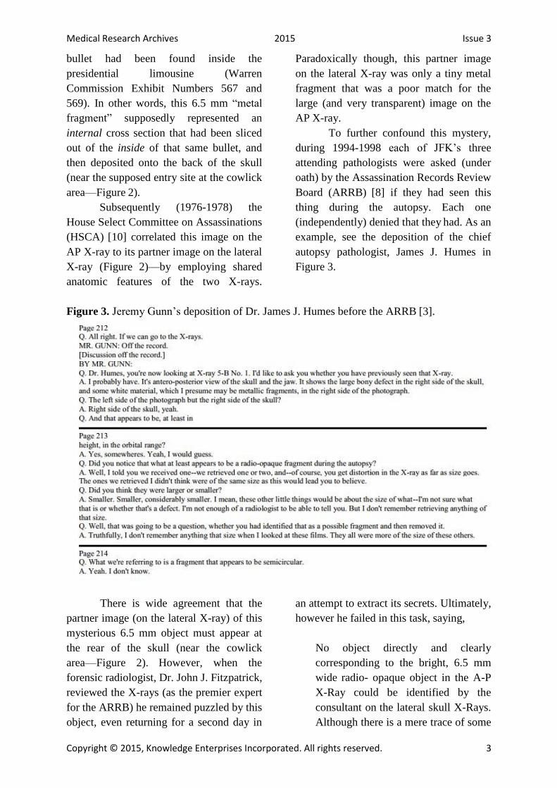
To further confound this mystery,
during 1994-1998 each of JFK’s three
attending pathologists were asked (under
oath) by the Assassination Records Review
Board (ARRB) [8] if they had seen this
thing during the autopsy. Each one
(independently) denied that they had. As an
example, see the deposition of the chief
autopsy pathologist, James J. Humes in
Figure 3.
Figure 3. Jeremy Gunn’s deposition of Dr. James J. Humes before the ARRB [3].
There is wide agreement that the
partner image (on the lateral X-ray) of this
mysterious 6.5 mm object must appear at
the rear of the skull (near the cowlick
area—Figure 2). However, when the
forensic radiologist, Dr. John J. Fitzpatrick,
reviewed the X-rays (as the premier expert
for the ARRB) he remained puzzled by this
object, even returning for a second day in
an attempt to extract its secrets. Ultimately,
however he failed in this task, saying,
No object directly and clearly
corresponding to the bright, 6.5 mm
wide radio- opaque object in the A-P
X-Ray could be identified by the
consultant on the lateral skull X-Rays.
Although there is a mere trace of some

Medical Research Archives 2015 Issue 3
Copyright © 2015, Knowledge Enterprises Incorporated. All rights reserved. 4
additional density near the fragment
bilocation at the vertex of the skull,
the consultant did not feel this object
was anywhere near the
density/brightness required for it to
correspond to the bright, radio-opaque
object on the A-P X-Ray. After briefly
speculating that the small metallic
density behind the right eye in the
lateral X- Rays might correspond to
the bright radio-opaque density in the
A-P X-Ray, this idea was abandoned
because neither the locations nor the
density/brightness of the 2 objects are
consistent [2].
For all practical purposes, after this
failed attempt (by the most appropriate
specialist for the task) this 6.5 mm object
become the most curious—and unsolved—
mystery in the history of diagnostic
radiology.
During the lifetime of the HSCA,
Larry Sturdivan served as its ballistics
consultant. In his subsequent book [14] he
emphasized that he had never, in his entire
career, seen a cross section of a bullet
deposited in such an odd fashion on a
skull. So, totally contrary to all prior
government investigations, he concluded
that the 6.5 mm object could not be a metal
fragment:
I’m not sure just what that 6.5 mm
fragment is. One thing I’m sure it is
NOT is a cross-section from the
interior of a bullet. I have seen literally
thousands of bullets, deformed and
undeformed, after penetrating tissue
and tissue simulants. Some were bent,
some torn in two or more pieces, but
to have a cross-section sheared out is
physically impossible. That fragment
has a lot of mystery associated with it.
Some have said it was a piece of the
jacket, sheared off by the bone and left
on the outside of the skull. I’ve never
seen a perfectly round piece of bullet
jacket in any wound. Furthermore, the
fragment seems to have great optical
density thin-face on [the frontal X-ray]
than it does edgewise [on the lateral
X-ray]….The only thing I can think is
that it is an artifact (e-mail from Larry
Sturdivan to Stuart Wexler on 9 March
1998).
This was a radical statement. After
all, the HSCA in particular, had relied on
the (metallic) authenticity of this fragment
in the most fundamental manner: based on
the supposed reality of this 6.5 mm object,
the HSCA had concluded that the bullet
(from the sole headshot) had deposited this
6.5 mm “metal fragment” near its entry site
at the back of the skull. So now, if this was
merely an artifact, what was to become of
the HSCA’s conclusion?
In 1993 I had two telephone
conversations with the (sole) autopsy
radiologist, Dr. John Ebersole. On the
second occasion, he telephoned me. That
call was recorded and later transcribed [7].
After (somewhat reluctantly) discussing
the autopsy, I asked him about this 6.5 mm
object—and Ebersole instantly stopped the
conversation. In fact, that was Ebersole’s
final comment to history about the JFK
autopsy, as he died shortly afterwards [4].
1. MATERIALS AND METHODS
For its unexpected entrance onto
the historical stage in 1968, and also for its
bizarre properties, a possible explanation
occurred to me—perhaps this 6.5 mm
object had indeed not been present on the
original X-ray, but had been added later
(e.g., in the darkroom). To pursue this
hypothesis I began (in the early 1990s
before the ARRB got underway) to query
older radiology technologists. In particular,

Medical Research Archives 2015 Issue 3
Copyright © 2015, Knowledge Enterprises Incorporated. All rights reserved. 5
I asked them: How exactly had they copied
X-ray films in the 1960s? With the further
assistance of a close colleague (diagnostic
radiologist, Dr. John Szabo) that riddle was
solved. In particular, I soon discovered a
technologist’s handbook [5]1 that
contained detailed recipes (p. 56) for
converting standard (double-sided) X-ray
films into duplicating films. (In that era,
Kodak did not make duplicating films—as
I was later able to confirm from their
inventory lists.) Cahoon even makes this
comment: “By variations of the copying
time, one may even improve on the
original” (p. 55).
Here then was the key to the 6.5
mm mystery: if an X-ray film could be
copied (with high fidelity), then it could
also be altered. The key step was to add a
second image during a second exposure.
For example, first the image of the original
film would be imprinted onto a duplicating
film via a light box in the darkroom (which
was how X-rays were then copied). But
then, before developing that duplicate film,
a second exposure would be made. In
particular, a piece of cardboard, with a 6.5
mm hole in it, could be precisely
positioned over the duplicate film—and
then a second exposure made (using only
this mask). I soon showed the feasibility of
this approach (using modern duplicating
film) by preparing fantastic X-rays with
such double exposures (Figures 4 and 5).
Figure 4. A superimposed scissors; its dark appearance implies that it is merely composed of
air, not of metal. I also added the white particles (via a multiple exposure) to mimic bullet
fragments.
Figure 5. A superimposed pteranodon from my then-young daughter’s plastic tracing kit. I
have described the resulting image as a “birdbrain.” The many dark opacities in the skull bone
suggest a diagnosis of multiple myeloma, for which this patient (now deceased) was receiving
radiation therapy (to the spine).
1The fifth edition of Cahoon’s book was published in 1961, and was favorably reviewed by M. Frank in the 1963 British
Journal of Radiology 36:223. That year was, ironically, also the year of JFK’s assassination.
Medical Research Archives 2015 Issue 3
Copyright © 2015, Knowledge Enterprises Incorporated. All rights reserved. 6
The JFK X-rays, however, have
emulsion on both sides, not just on one
side, but my double-exposed X-rays
(Figures 4 and 5) had emulsion only on
one side (as was then typical of modern
duplicating film). When I followed the
recipes in Cahoon’s book (for converting
standard, double-sided X-ray film into
duplicating film) and prepared double
exposures by using these, every film
developed a strange greenish color. I soon
learned that, sometime after 1963, Kodak
had added a color dye to its standard,
double-sided films. Presumably that was
done precisely so that copies could easily
be distinguished from originals (quite
possibly so that altered X-ray images could
easily be detected). But that was definitely
not the case during the era of JFK’s
autopsy.
Since the 6.5 mm object was so
strangely transparent, it seemed quite clear
what had happened: this 1963 secretive,
darkroom worker had simply overdone the
second exposure. If so, I reasoned, it
should be feasible to prove this conjecture-
by means of optical densitometry. Optical
density quantitatively describes the
lightness or darkness of specific points on
the X- film: one simply measures the
transmission of light through a specific
aperture on an optical densitometer (Figure
6). For example, if 1/5 of the light is
transmitted (this area would appear quite
transparent to light), then the optical
density would be2
OD = -log10 (1/5) = 0.7.
Or if 1/100 of the light is
transmitted (this area would appear quite
dark on the X-ray film), then the optical
density would be
OD = -log10 (1/100) = 2.0.
In order to accommodate the
human eye, in clinical X-ray films the OD
range is typically chosen to be 0.5 to 2.0
(by appropriately setting the voltage,
current, and exposure times of the X-ray
machine).
Figure 6. Tobias optical densitometer
2 See “Optical Density” at http://www.semrock.com/optical-density.aspx. Areas on the X-ray film that appear transparent (to
light) are called radio-opaque, which can seem paradoxical. These areas are transparent (to light) because the real world
object (e.g., lead, or in JFK’s case, mercury-silver amalgams) was opaque to X-rays. In these transparent areas on the film,
the (original) silver salt is washed off the film during development. On the other hand, in areas where mostly unimpeded X-
rays have struck the film (such as for the air around JFK’s head), the X-rays convert the silver salt to black metallic silver,
which is not washed off during development. So naturally these areas (e.g., air pockets) are visibly dark. (Note: this
explanation is somewhat oversimplified.)

Medical Research Archives 2015 Issue 3
Copyright © 2015, Knowledge Enterprises Incorporated. All rights reserved. 7
The next step was to adapt our
department’s scanning drive (essentially a
precisely calibrated gear mechanism)3 so
that it could be used with the optical
densitometer. After devising a simple jig
for attaching this device to the
densitometer, I took the equipment with
me to the National Archives. I would now
be able to scan across the 6.5 mm object
while taking high resolution OD data.
During nine visits to the National
Archives, I obtained hundreds of OD data
points.
2. RESULTS—AT THE NATIONAL
ARCHIVES
As I compared the ODs of the 6.5
mm object to the ODs of JFK’s teeth, a
stunning paradox quickly arose. The AP X-
ray shows multiple overlapping teeth,4 all
with likely mercury-silver amalgams—as
can clearly be appreciated from both lateral
skull X-rays taken at the autopsy. But here
was the problem: the OD (approximately
0.6) of the 6.5 mm object implied a
metallic thickness (front to back) even
greater than all of those (at least four)
overlapping amalgams (Table 1). Of
course, that made no sense, especially
since the lateral X- ray did not confirm
such a thickness for the supposed partner
image of the 6.5 mm object. In fact, on the
lateral X-ray, the partner image of the 6.5
mm object is only a tiny metal fragment
(Figure 2). Of course, subsequent experts
(e.g., chiefly John Fitzpatrick, but others as
well) had already made that same point,
based solely on their naked eye
inspections. But now my quantitative OD
data had confirmed their visual impression.
(Actually, my data had been obtained well
before Fitzpatrick’s review). This bizarre
result was precisely what should have been
expected if the 6.5 mm object had merely
been added in the darkroom—without
proper control over the duration of the
second exposure.
Table 1. OD comparison of JFK’s teeth (with dental amalgams) vs. the 6.5 mm object. The 7
x 2 mm metal fragment is visible on both JFK’s AP and lateral X-rays (Figures 1 and 2), and
it was removed during the autopsy. ODs shown here are representative only. Actually, many
OD data points were taken.
3 This scanning equipment is commonly used in departments of radiation oncology to calibrate dose distributions (by using
water tanks as targets), e.g., see http://www.ptw.de/sla48_air_scanner_table.html?&cId=. 4 The teeth have been cropped out of publicly available images of JFK’s skull X-rays, but JFK’s (pre-mortem) dental images
were published by the HSCA at http://jfkassassination.net/russ/infojfk/jfk1/1exhf295p150.jpg. That there is a match between
these two different sets of X-ray images is proof that the body at the autopsy really was JFK’s.

Medical Research Archives 2015 Issue 3
Copyright © 2015, Knowledge Enterprises Incorporated. All rights reserved. 8
Another visual feature leapt out at
me as I viewed the 6.5 mm object with my
then- extremely myopic (-9.0 diopter)
eyes: I was seeing a phantom effect—as a
result of a double exposure.5 As shown in
Figure 7, I could actually see the original
(crescent-shaped) metal fragment (the one
that matched the authentic image on the
lateral X-ray at the back of the skull). On
the AP X-ray, the authentic metal fragment
lay at the anatomic right side of the 6.5 mm
object, but it was located entirely inside of
the 6.5 mm object. In fact, it appeared that
the darkroom worker had positioned his
double-exposed 6.5 mm image to precisely
match the (anatomic) right border of the
authentic metal fragment. Furthermore, by
doing so, he had guaranteed that the 6.5
mm image would not be left without a
partner image on the lateral X- ray. (On the
other hand, if he had not matched the 6.5
mm image to an authentic metal fragment,
the 6.5 mm object would have had no
partner image on the lateral X-ray, and the
forgery would have been obvious.)
Figure 7. My sketch of the 6.5 mm object, as drawn at the Archives. The crescent-shaped
(cross-hatched) area represents the authentic fragment—the real one that lay at the back of
JFK’s skull (Figure 2). Scattered tiny metal fragments are identified by arrows, including one
(paradoxically) inside the 6.5 mm object.
I could also see (Figure 7) tiny
pieces of metal adjacent to the 6.5 mm
object, but one tiny particle actually lay
inside of this 6.5 mm object. The separate
appearance of this tiny particle, as well as
the separate appearance of the crescent-
shaped, original fragment (actually located
at the back of the skull) are both examples
of the phantom effect. This is a well-
known Hollywood phenomenon, which
results from a photographic double
exposure (Figure 8).6
5 This observation (of a phantom effect) was confirmed on 22 April 2015 by Dr. Mike Chesser (a neurologist) during his own
visit to the JFK X-rays at the National Archives (personal communication, publication pending). He also measured the ODs
of the 6.5 mm object, of the petrous bone, and of the posterior “White Patch” (using an optical densitometer supplied by the
Archives). His results for these ODs are in excellent agreement with mine. 6 Like many other amateurs, I have accidentally produced this effect myself when my old-fashioned, film-based camera
failed to advance the film. Images of double exposures may be seen at
https://www.google.com.mx/webhp?sourceid=chrome-instant&rlz=1C1CHFX_enUS629US629&ion=1&espv=2&ie=UTF-
8#q=double%20exposure%20phantom%20image.
Medical Research Archives 2015 Issue 3
Copyright © 2015, Knowledge Enterprises Incorporated. All rights reserved. 9
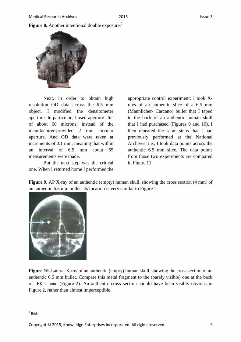
Figure 8. Another intentional double exposure.7
Next, in order to obtain high
resolution OD data across the 6.5 mm
object, I modified the densitometer
aperture. In particular, I used aperture slits
of about 60 microns, instead of the
manufacturer-provided 2 mm circular
aperture. And OD data were taken at
increments of 0.1 mm, meaning that within
an interval of 6.5 mm about 65
measurements were made.
But the next step was the critical
one. When I returned home I performed the
appropriate control experiment: I took X-
rays of an authentic slice of a 6.5 mm
(Mannlicher- Carcano) bullet that I taped
to the back of an authentic human skull
that I had purchased (Figures 9 and 10). I
then repeated the same steps that I had
previously performed at the National
Archives, i.e., I took data points across the
authentic 6.5 mm slice. The data points
from those two experiments are compared
in Figure 11.
Figure 9. AP X-ray of an authentic (empty) human skull, showing the cross section (4 mm) of
an authentic 6.5 mm bullet. Its location is very similar to Figure 1.
Figure 10. Lateral X-ray of an authentic (empty) human skull, showing the cross section of an
authentic 6.5 mm bullet. Compare this metal fragment to the (barely visible) one at the back
of JFK’s head (Figure 2). An authentic cross section should have been visibly obvious in
Figure 2, rather than almost imperceptible.
7 Ibid.
Medical Research Archives 2015 Issue 3
Copyright © 2015, Knowledge Enterprises Incorporated. All rights reserved. 10
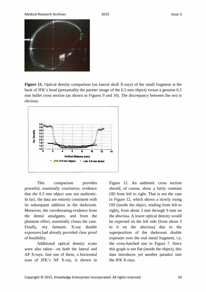
Figure 11. Optical density comparison (on lateral skull X-rays) of the small fragment at the
back of JFK’s head (presumably the partner image of the 6.5 mm object) versus a genuine 6.5
mm bullet cross section (as shown in Figures 9 and 10). The discrepancy between the two is
obvious.
This comparison provides
powerful, essentially conclusive, evidence
that the 6.5 mm object was not authentic.
In fact, the data are entirely consistent with
its subsequent addition in the darkroom.
Moreover, the corroborating evidence from
the dental amalgams, and from the
phantom effect, essentially closes the case.
Finally, my fantastic X-ray double
exposures had already provided clear proof
of feasibility.
Additional optical density scans
were also taken—on both the lateral and
AP X-rays. Just one of these, a horizontal
scan of JFK’s AP X-ray, is shown in
Figure 12. An authentic cross section
should, of course, show a fairly constant
OD from left to right. That is not the case
in Figure 12, which shows a slowly rising
OD (inside the object, reading from left to
right), from about 3 mm through 9 mm on
the abscissa. A lower optical density would
be expected on the left side (from about 3
to 6 on the abscissa) due to the
superposition of the darkroom double
exposure over the real metal fragment, i.e,
the cross-hatched one in Figure 7. Since
this graph is not flat (inside the object), this
data introduces yet another paradox into
the JFK X-rays.

Medical Research Archives 2015 Issue 3
Copyright © 2015, Knowledge Enterprises Incorporated. All rights reserved. 11
Figure 12. Horizontal scan of the 6.5 object on JFK’s AP X-ray. The left side here
corresponds to JFK’s anatomic left. This is the same side that contains the authentic metal
fragment (shown cross-hatched in Figure 7). A lower optical density would be expected on
the left side due to the superposition of the authentic metal fragment over the darkroom
double exposure. That is precisely what this scan shows.
Additional scans (not shown here)
were taken through the small metal
fragment at the back of the skull (Figure
2—the lateral X-ray). These scans were
taken both horizontally and vertically. On
JFK’s AP X-ray, a segment is missing
(from the nearly perfect circle) at the
inferior pole of the 6.5 mm object.
Therefore, these scans on the lateral X-ray
should demonstrate noticeably less metal
at the inferior pole of this object. In fact,
they do not, which is yet another paradox.
Of course, if this 6.5 mm image actually
derived from a double exposure in the
darkroom, then all of these paradoxes
would be expected.
3. DISCUSSION: MOTIVES AND A
TIMELINE
The only viable explanation for the
6.5 mm object is this: it is indeed an
artifact, one that was deliberately
superimposed (in the dark room) directly
over a pre-existing, authentic piece of
metal that lay at the back of the skull (i.e.,
the one that is barely visible in Figure 2).
That explanation addresses all of the
mysteries of this image. In particular, its
diameter was deliberately chosen to match
the caliber of the 6.5 mm carbine, and it
was intentionally placed directly over a
pre-existing (very small) metal fragment.
An (inattentive) overexposure led to its
remarkable transparency (and to its oddly
curious ODs). Furthermore, the timing of
this superposition—after the autopsy—
explains why no one saw it at the autopsy.
Finally, it may also explain why the
radiologist, Dr. Ebersole, refused to
discuss this artifact with me. After all, he
was the single individual most likely to
possess the required expertise and
creativity to perform X–ray alteration.
So when was this 6.5 mm image
added to the original X-ray? One event
provides a clue: several weeks after
November 22, 1963, Dr. Ebersole was
called to the White House by the Secret
Service (who controlled all of the autopsy
materials). As preposterous as it seems,
Ebersole claimed that the purpose of his

Medical Research Archives 2015 Issue 3
Copyright © 2015, Knowledge Enterprises Incorporated. All rights reserved. 12
visit was to assist in preparing a bust of
JFK. While there (he also reported) he
drew a straight pencil line obliquely across
one lateral X-ray.8 More likely, in my
opinion, the reason for his summons to the
White House was to see how he would
react to the now-altered X-rays. Based on
this episode then, the alteration must have
occurred within several weeks (quite
possibly immediately) after the
assassination. But there is one more clue to
the timeline – the recollections of Jerrol
Custer, the radiology technologist. He
recalled (to me personally, as well as
publicly) that the morning after the
assassination, he was called into the
radiology suite (by Dr. Ebersole) and was
tasked with taking X-rays of bullet
fragments taped to skull X-rays. In my
opinion, however, none of these X-rays
were used, especially after it occurred to
the master forger that the alteration was
easier to perform in the darkroom via a
double exposure.
The final question, of course, is
this: Why was this forgery necessary? The
answer to that question has been proposed
in dozens, if not hundreds, of books and
articles over the decades9, but the
proximate motive must have been this: It
was to implicate Oswald and his supposed
6.5 mm Mannlicher-Carcano carbine. In
particular, with Oswald as the lone
gunman, conspiracy had been ruled out,
and a supposed Cold War catastrophe
could then be averted (e.g., nuclear war
with the Soviet Union). Of course, as a
corollary, a conspiracy of any stripe could
also (conveniently) be ruled out. However,
these issues are all beyond the scope of this
essay.
CONCLUSION
The 6.5 mm object was not
described in the autopsy report nor was it
seen (by anyone) on the original autopsy
X-rays. Among the many (dozens) of
individuals at the autopsy, no one saw it,
even though the X-rays were on public
display during the autopsy. Nor has anyone
at the autopsy ever recalled a single
conversation about it. This peculiar object
simply materialized in the public record,
for the first time (four years later) with the
1968 Clark Panel report.
This artifact was added to the JFK
AP skull X-ray (in the darkroom) via a
double exposure of a 6.5 mm aperture
(e.g., via a 6.5 mm hole in a piece of
cardboard). In this process, the first step
was to imprint the image from the original
X-ray onto a duplicate film (via a light box
in the dark room). The second step was
another exposure that imprinted the 6.5
mm image onto the duplicate film (i.e.,
superimposing it over the image of the
original X-ray). This duplicate film was
then developed to yield the image seen in
Figure 1. This process inevitably produces
a phantom effect, whereby objects (e.g.,
bullet fragments in this case) on the
original film are seen separately from the
superimposed 6.5 mm image. On JFK’s
AP skull X-ray, the original metal
fragment (that lay at the back of the skull)
can be seen separately through the 6.5 mm
image (Figure 7). Furthermore, the double
exposure was unprofessional: it produced a
significant overexposure of the 6.5 mm
image, so much so that the resulting OD
implies a very long section of metal (from
front to back—Table 1).
8 I observed that this pencil line lay on only one side of the film. This means that the film that I saw had not been copied since
Ebersole drew his line. 9 For just one of these books, especially for readers interested in the whodunits in the JFK case, see Bloody Treason by Noel
Twyman [15].
Medical Research Archives 2015 Issue 3
Copyright © 2015, Knowledge Enterprises Incorporated. All rights reserved. 13
There is, of course, no such partner
image on the lateral X-ray, which
immediately exposes this object as an
artifact.
On JFK’s lateral X-ray, high
resolution OD scans of the posterior skull
fragment (Figure 2), and comparison of
these ODs to a control experiment using an
authentic bullet cross section (Figures 9
and 10) also yielded highly paradoxical
results. These results are inexplicable if the
6.5 mm object is an authentic bullet
fragment. This conclusion is consistent
with the chief consultant for the ARRB
(Dr. John Fitzpatrick), who actually
admitted that he could not explain the
mysteries of this 6.5 mm image.
The addition of this 6.5 mm image
to the AP X-ray was completed during the
first several weeks (perhaps even
immediately) after November 22, 1963. Its
proximate purpose could only have been to
implicate the 6.5 mm Mannlicher-Carcano
carbine (supposedly owned by Oswald) in
the assassination. Its ultimate purpose,
however, awaits resolution by professional
historians, who have been remarkably
reticent about accepting responsibility for
their task.
CONFLICT OF INTEREST
The author has no conflict of
interest to disclose.
Medical Research Archives 2015 Issue 3
Copyright © 2015, Knowledge Enterprises Incorporated. All rights reserved. 14
REFERENCES
1. “1968 Panel Review of
Photographs, X-Ray Films, Documents
and Other Evidence Pertaining to the Fatal
Wounding of President John E Kennedy on
November 22, 1963, in Dallas, Texas”
[Clark Panel Report] at
http://www.jfklancer.com/ClarkPanel.html
2. “ARRB staff report of
observations and opinions of forensic
radiologist Dr. John J. Fitzpatrick, after
viewing the JFK autopsy photos and X-
rays” at
http://www.maryferrell.org/showDoc.html
?docId=145280&relPageId=225
3. “The [ARRB] deposition of
Dr. James J. Humes” at
http://jfkassassination.net/russ/testimony/hu
mesa.htm
4. Author, “A Telephone
Conversation with Dr. John Ebersole” at
http://jfkassassination.net/russ/testimony/h
umesa.htm
5. Cahoon, John B. 1961.
Formulating X-ray Techniques (5th
edition). Duke University Press, Durham,
North Carolina at
http://europepmc.org/backend/ptpmcrender
.fcgi?accid=PMC197800&blobtype=pdf
6. Fetzer, James H., editor.
1998. Assassination Science: Experts
Speak out on the Death of JFK. Catfeet
Press, an imprint of Open Court, Peru,
Illinois
7. Fetzer, James H., editor.
2000. Murder in Dealey Plaza: What We
Know Now that We Didn’t Know Then
about the Death of JFK. Catfeet Press, an
imprint of Open Court, Peru, Illinois
8. Final Report of the
Assassination Records Review Board
(1998) at
http://fas.org:8080/sgp/advisory/arrb98/ind
ex.html
9. Frank, M. 1963. British
Journal of Radiology 36:223
10. House Select Committee on
Assassinations Final Report (1979) at
https://www.maryferrell.org/showDoc.ht
ml?docId=800
11. Images of double exposures
at
https://www.google.com.mx/webhp?source
id=chrome-
instant&rlz=1C1CHFX_enUS629US629&
ion=1&espv=2&ie=UTF-
8#q=double%20exposure%20phantom%20
image
12. “JFK Dental X-rays” at
http://jfkassassination.net/russ/infojfk/jfk1/
1exhf295p150.jpg
13. Report of the President's
Commission on the Assassination of
President Kennedy [The Warren Report] at
http://www.archives.gov/research/jfk/warr
en-commission-report/
14. Sturdivan, Larry. 2005. The
JFK Myths: A Scientific Investigation of
the Kennedy Assassination. Paragon Press,
St. Paul, Minnesota
15. Twyman, Noel. 1997.
Bloody Treason. Laurel Publishing,
Rancho Santa Fe, California