the length of vermeer’s studio - … · the length of vermeer’s studio . chew mei ru madeleine...
TRANSCRIPT

1
Undergraduate Research Opportunity Programme in Science
THE LENGTH OF VERMEER’S STUDIO
Chew Mei Ru Madeleine
Lee Yiwei Christina
Supervisor: Associate Professor Helmer Aslaksen
Department of Mathematics
National University of Singapore
Academic Year 2008/2009

2
Acknowledgement
We thank our project supervisor A/P Helmer Aslaksen for
his guidance, invaluable advice and probing questions,
which have contributed significantly to our more in-depth
appreciation of perspective geometry in art. We are
grateful for his patience and sense of humour, which have
inspired us to complete this project with passion and
academic rigour.

3
CONTENTS
1 Introduction 4
2 Projective Geometry in Paintings 5
3 The Possible Use of the Camera Obscura in the Works of Johannes
Vermeer 8
4 Key Terms and Concepts in the Papers of Tomas Garcia-Salgado 10
5 The Papers of Tomas Garcia-Salgado 17
5.1 The Music Lesson 18
5.2 A Lady Standing at a Virginal 27
5.3 Observer Points of The Music Lesson and A Lady Standing at a Virginal, and Side Vanishing Point of A Lady Standing at a Virginal 32
5.4 Trimming the PPbw 35
5.5 The Music Lesson and A Lady Standing at a Virginal 38
6 Analysis and Discussion 47
6.1 Analysis on Garcia-Salgado’s Calculations for The Music Lesson 47
6.2 The Assumed Height of the Man in The Music Lesson 57
7 Conclusion 58
BIBLIOGRAPHY 60
APPENDICES 62

4
Abstract
The purpose of this project is to verify that the artist Johannes Vermeer painted The
Music Lesson and A Lady Standing at a Virginal in the same room. The main objective is to
elucidate the methods used by Tomas Garcia-Salgado by discussing the numerical values
mentioned in his paper and comparing the calculations with the findings in Aditya Liviandi’s
thesis.
1 Introduction
Johannes Vermeer’s alleged use of the camera obscura in the creation of his artwork
has been a controversial topic discussed for many years. Philip Steadman, in Vermeer’s
Camera, provides evidence that Vermeer used the camera obscura to create his paintings.
Steadman uses the inverse perspective method to reconstruct the studio using the reflection of
the mirror in the The Music Lesson (ML) [1]. Steadman also argues that Vermeer painted at
least six paintings in the same room. Based on the findings of Steadman, Tomas Garcia-
Salgado attempts to use his Modular Perspective method [2] to confirm and extend the
findings of Steadman, that the room depicted in Vermeer’s paintings are the same.
Unfortunately, many of the statements made by Garcia-Salgado are not explained fully. In his
thesis Reconstruction of Vermeer’s The Music Room, Aditya Liviandi attempts to reconstruct
Vermeer’s studio using a method that is different from both Steadman and Garcia-Salgado
[3]. This paper aims to elucidate the methods used by Garcia-Salgado in calculating the
numerical values mentioned in his paper Modular Perspective and Vermeer’s Room, and
compare the findings of Garcia-Salgado with that of Liviandi.
5
2 Projective Geometry in Paintings
To understand the geometry behind Vermeer’s works, we first need to understand the
concepts of projective geometry used in paintings. Projective geometry refers to the field of
Mathematics which assigns points on a two-dimensional image to points in three-dimensional
real-world space and vice versa [4]. A painting can be regarded as a two-dimensional image.
It has been speculated that Vermeer’s paintings were created using a camera. Hence, if
Vermeer had used a camera to create his painting, the observer point (O) is the position of the
camera lens when a photograph of the scene is captured. Otherwise, the observer point is the
eye of the painter when the painting is being created.
The depiction of objects in a painting is constructed by linear perspective, which is a
mathematical representation of three-dimensional objects on a two-dimensional surface as
viewed by the observer [5]. Using this method, any set of parallel lines in three-dimensional
space, which are depicted in a painting and are not parallel to the plane of the painting, will in
its two-dimensional representation converge at a point. This point is called a vanishing point
(vp). When the set of parallel lines in three-dimensional space are orthogonal to the plane of
the painting, the lines are called orthogonals, and the point at which they converge is called
the central vanishing point (cvp).
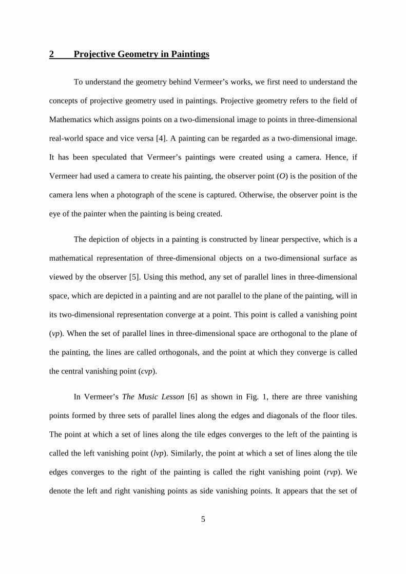
In Vermeer’s The Music Lesson [6] as shown in Fig. 1, there are three vanishing
points formed by three sets of parallel lines along the edges and diagonals of the floor tiles.
The point at which a set of lines along the tile edges converges to the left of the painting is
called the left vanishing point (lvp). Similarly, the point at which a set of lines along the tile
edges converges to the right of the painting is called the right vanishing point (rvp). We
denote the left and right vanishing points as side vanishing points. It appears that the set of
6
parallel lines along the tile diagonals converge orthogonally into the painting. If this is true,
the left and right vanishing points will be equidistant from the point that this set of lines
converges to, and this point of convergence will be the central vanishing point (cvp).
However, it will be shown later in this paper that this vanishing point is not the central
vanishing point. To elucidate the concepts in his papers, we first assume, as Garcia-Salgado
did in his paper Modular Perspective and Vermeer’s Room [2], that the vanishing point
formed by the lines along the tile diagonals is the central vanishing point in this paper.
Additionally, since the sets of parallel lines lie on the horizontal floor in three-dimensional
space, all three aforementioned vanishing points lie on the horizon.
Fig. 1 Left, central and right vanishing points indicated on The Music Lesson
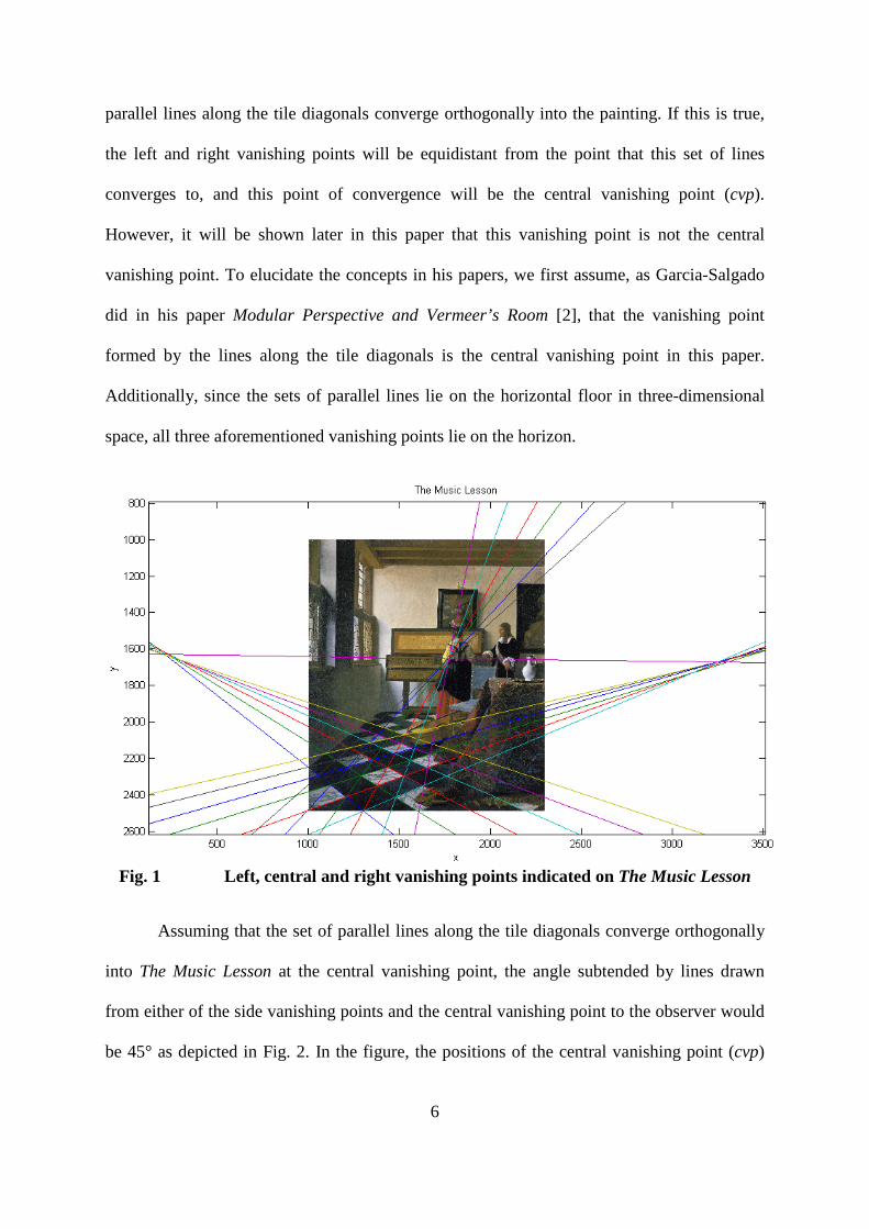
Assuming that the set of parallel lines along the tile diagonals converge orthogonally
into The Music Lesson at the central vanishing point, the angle subtended by lines drawn
from either of the side vanishing points and the central vanishing point to the observer would
be 45° as depicted in Fig. 2. In the figure, the positions of the central vanishing point (cvp)
7
and the right vanishing point (rvp) on the top view of the painting are labelled as points A and
B respectively.
Fig. 2 Top view of The Music Lesson depicting the positions of the observer,
central vanishing point, right vanishing point and the horizontal positions of the two
vanishing points on the plane of the painting
Since the triangle formed by joining the points O, A and B is an isosceles right triangle, the
length of OA is equal to the length of AB. This implies that the perpendicular distance of the
observer from the plane of the painting is equal to the distance between the positions of the
central and right vanishing points on the painting. This is also true when we replace the right
vanishing point with the left vanishing point. Therefore, we have the formula: perpendicular
distance of the observer from the plane of the painting = cvp-lvp = cvp-rvp, where A-B
indicates the distance between any two points A and B.
O cvp
rvp
plane of the painting
45°
A
B

8
3 The Possible Use of the Camera Obscura in the Works of Johannes
Vermeer
The camera obscura is a device which includes a lens or a pinhole, with which an
image of a scene viewed by an observer can be projected onto a screen. The projected image
on the screen can then be traced. The camera obscura is the precursor to the photographic
camera.
Many people have speculated that the Dutch artist Johannes Vermeer (1632-75) used
the camera obscura to help him create his paintings [6]. The speculations on Vermeer’s
possible use of a camera obscura are based on the general observations about his paintings.
Firstly, Vermeer’s paintings have a “photographic perspective” as described by the
American etcher and lithographer James Pennell [6]. Pennell highlighted the
disproportionately large figure of the soldier in the foreground of Soldier and the Laughing
Girl. The perspective of this painting seems like one taken with a camera, which is an
unusual perspective for a 17th century painting. Pennell was the first to suggest that Vermeer
used the camera obscura.
Secondly, the maps in some of Vermeer’s paintings are precisely copied from the
original maps, a piece of evidence presented by the historian James Welu [6]. The maps hung
on the walls in Vermeer’s paintings are real maps which still exist today, and the camera
obscura was used in the 18th and 19th centuries for copying existing prints such as maps.
Thirdly, Vermeer’s treatment of highlights on reflective surfaces suggests that he uses
the camera obscura. Metal and ceramics in Vermeer’s paintings show small circles of white
or yellow pigment, which are suggested to be the “circles of confusion” seen when we view
bright highlights through a low quality or out-of-focus lens [6].
9
Finally, the British artist Lawrence Gowing described in his monograph on Vermeer
that the pattern of light and shade of the subject in Vermeer’s paintings are transcribed with
little of the underlying drawing, which most artists will use to build up a representation [6].
Gowing argues that Vermeer’s pattern of light and shade of the subject is attributed to a
technique which is based on prolonged observation of patterns of light which fall on a camera
screen. The speculations remained without any actual evidence that Vermeer had indeed used
the camera obscura in creating his paintings.
Besides the speculations made based on the general observations of Vermeer’s
paintings, the availability of the camera obscura to Vermeer also suggests Vermeer’s possible
use of the camera obscura in his paintings [6]. Holland was a centre for the manufacture of
high quality optical instruments in the 17th century. Furthermore, there were books like della
Porta’s Magia Naturalis (1558), which described the camera obscura and its possible use in
painting, circulating in Holland in the 1600s. The camera obscura was also used by
astronomers, such as Johannes Kepler, who made detailed studies of sunspots in the early
1600s. Therefore, the camera obscura was known in Holland during Vermeer’s lifetime.
However, again, there is no documentary evidence that Vermeer owned a camera obscura
device or was familiar with it.
In Vermeer’s Camera [1], Philip Steadman, Professor of Architectural and Urban
Morphology at the Open University in United Kingdom, presents an analysis of the
perspective geometry of Vermeer’s paintings. The analysis provides evidence for Vermeer’s
use of the camera obscura.
Steadman argues that most of Vermeer’s paintings were painted in the same room and
Vermeer constructed his perspective views with a high precision that the shape and
dimensions of the room can be measured to a high degree of accuracy. Steadman was able to
10
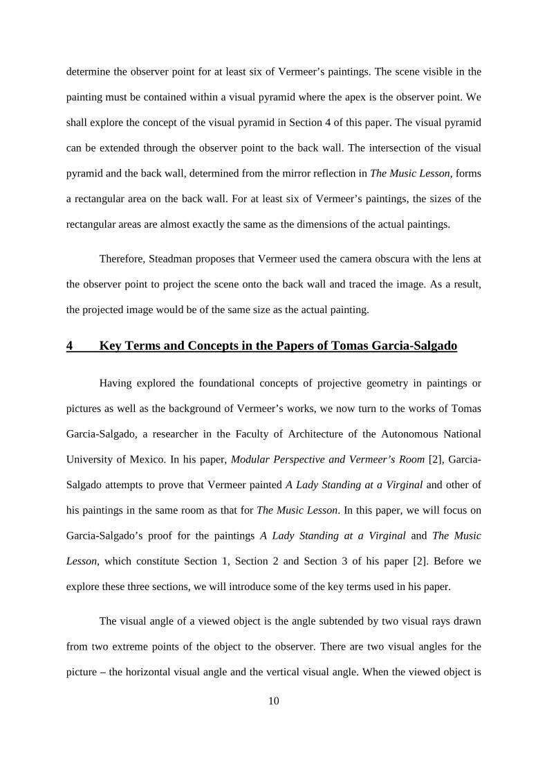
determine the observer point for at least six of Vermeer’s paintings. The scene visible in the
painting must be contained within a visual pyramid where the apex is the observer point. We
shall explore the concept of the visual pyramid in Section 4 of this paper. The visual pyramid
can be extended through the observer point to the back wall. The intersection of the visual
pyramid and the back wall, determined from the mirror reflection in The Music Lesson, forms
a rectangular area on the back wall. For at least six of Vermeer’s paintings, the sizes of the
rectangular areas are almost exactly the same as the dimensions of the actual paintings.
Therefore, Steadman proposes that Vermeer used the camera obscura with the lens at
the observer point to project the scene onto the back wall and traced the image. As a result,
the projected image would be of the same size as the actual painting.
4 Key Terms and Concepts in the Papers of Tomas Garcia-Salgado
Having explored the foundational concepts of projective geometry in paintings or
pictures as well as the background of Vermeer’s works, we now turn to the works of Tomas
Garcia-Salgado, a researcher in the Faculty of Architecture of the Autonomous National
University of Mexico. In his paper, Modular Perspective and Vermeer’s Room [2], Garcia-
Salgado attempts to prove that Vermeer painted A Lady Standing at a Virginal and other of
his paintings in the same room as that for The Music Lesson. In this paper, we will focus on
Garcia-Salgado’s proof for the paintings A Lady Standing at a Virginal and The Music
Lesson, which constitute Section 1, Section 2 and Section 3 of his paper [2]. Before we
explore these three sections, we will introduce some of the key terms used in his paper.
The visual angle of a viewed object is the angle subtended by two visual rays drawn
from two extreme points of the object to the observer. There are two visual angles for the
picture – the horizontal visual angle and the vertical visual angle. When the viewed object is
11
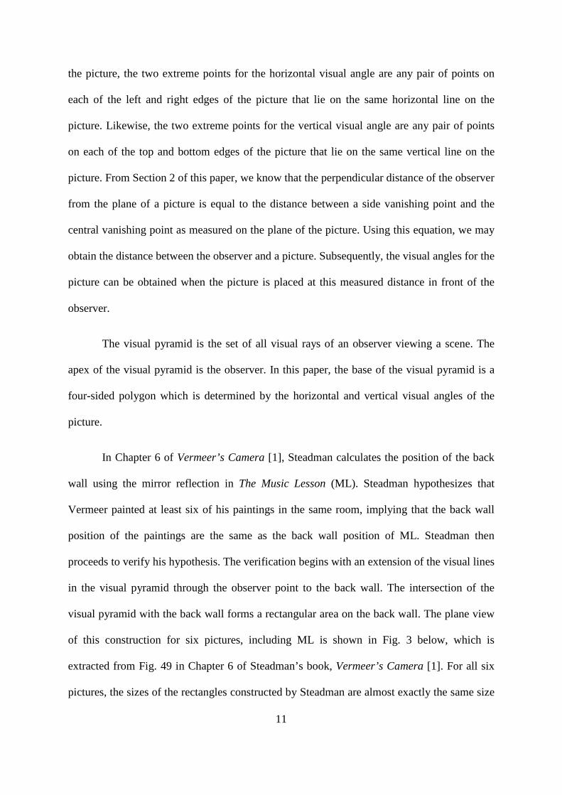
the picture, the two extreme points for the horizontal visual angle are any pair of points on
each of the left and right edges of the picture that lie on the same horizontal line on the
picture. Likewise, the two extreme points for the vertical visual angle are any pair of points
on each of the top and bottom edges of the picture that lie on the same vertical line on the
picture. From Section 2 of this paper, we know that the perpendicular distance of the observer
from the plane of a picture is equal to the distance between a side vanishing point and the
central vanishing point as measured on the plane of the picture. Using this equation, we may
obtain the distance between the observer and a picture. Subsequently, the visual angles for the
picture can be obtained when the picture is placed at this measured distance in front of the
observer.
The visual pyramid is the set of all visual rays of an observer viewing a scene. The
apex of the visual pyramid is the observer. In this paper, the base of the visual pyramid is a
four-sided polygon which is determined by the horizontal and vertical visual angles of the
picture.
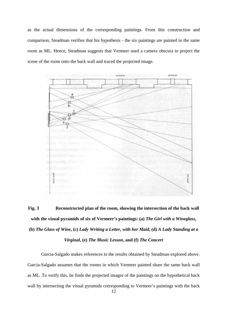
In Chapter 6 of Vermeer’s Camera [1], Steadman calculates the position of the back
wall using the mirror reflection in The Music Lesson (ML). Steadman hypothesizes that
Vermeer painted at least six of his paintings in the same room, implying that the back wall
position of the paintings are the same as the back wall position of ML. Steadman then
proceeds to verify his hypothesis. The verification begins with an extension of the visual lines
in the visual pyramid through the observer point to the back wall. The intersection of the
visual pyramid with the back wall forms a rectangular area on the back wall. The plane view
of this construction for six pictures, including ML is shown in Fig. 3 below, which is
extracted from Fig. 49 in Chapter 6 of Steadman’s book, Vermeer’s Camera [1]. For all six
pictures, the sizes of the rectangles constructed by Steadman are almost exactly the same size
12
as the actual dimensions of the corresponding paintings. From this construction and
comparison, Steadman verifies that his hypothesis - the six paintings are painted in the same
room as ML. Hence, Steadman suggests that Vermeer used a camera obscura to project the
scene of the room onto the back wall and traced the projected image.
Fig. 3 Reconstructed plan of the room, showing the intersection of the back wall
with the visual pyramids of six of Vermeer’s paintings: (a) The Girl with a Wineglass,
(b) The Glass of Wine, (c) Lady Writing a Letter, with her Maid, (d) A Lady Standing at a
Virginal, (e) The Music Lesson, and (f) The Concert
Garcia-Salgado makes references to the results obtained by Steadman explored above.
Garcia-Salgado assumes that the rooms in which Vermeer painted share the same back wall
as ML. To verify this, he finds the projected images of the paintings on the hypothetical back
wall by intersecting the visual pyramids corresponding to Vermeer’s paintings with the back

13
wall. In Modular Perspective and Vermeer’s Room [2], Garcia-Salgado further calculates the
dimensions of these projected images and finds them to be acceptably close to the actual
dimensions of the paintings.
There is no concrete evidence for us to ascertain that the actual back wall of the room
is the back wall position on which the images of the pictures were projected. It is possible for
the reflected object assumed as the back wall in the mirror of ML to be an additional vertical
object placed at that position rather than the actual back wall of the room. For example, the
vertical object could be one of the walls of the camera obscura cubicle used by Vermeer.
However, to shed light on Garcia-Salgado’s papers, we will assume in this paper as he did
that the vertical object where the images of the pictures are projected on is the actual back
wall of the room.
We will now discuss the method of Modular Perspective used by Garcia-Salgado.
Garcia-Salgado introduces the term “module” to refer to an object at a certain depth in the
picture, which can be regarded as a unit of measurement for lengths of other objects at the
same depth [2]. In his papers, the module is taken to be the tile diagonal length at the depth at
which the length of an object is measured. For example, to measure the height of the man in
ML, the module is taken to be the tile diagonal at the depth of the man.
An arbitrary image of a painting can be shifted along the visual pyramid. The length
of the tile diagonal at the bottom edge of a painting is denoted by n. We introduce the term
Perspective Plane (PP) to refer to the picture which is shifted along the line of sight and can
be positioned at any arbitrary position within the visual pyramid. As PP is shifted within the
visual pyramid, it is scaled proportionately to fit exactly into the initial visual pyramid at all
positions along the line of sight and the visual pyramid does not change. The size of PP
increases as the image is shifted further away from the observer and vice versa. The absolute
14
length of n changes by the same scaling factor by which the image size changes.
Consequently, the absolute distance between the central and side vanishing points also
changes by the same scaling factor by which the image size changes. As a result, the number
of modules between the central and side vanishing points remains the same when PP is
shifted along the line of sight in the visual pyramid.
In contrast with Garcia-Salgado’s notation, we denote the Perspective Plane in the
visual pyramid that touches the floor as the Perspective Plane on the floor (PPf), whereas
Garcia-Salgado denotes it by PP [2]. This is done to differentiate PPf, which touches the
floor in three-dimensional real-world space, from the previously defined Perspective Plane
(PP), which can be arbitrarily positioned along the line of sight in the visual pyramid. The
perpendicular distance between PPf and the observer point, O, is denoted by O-PPf. It is
noteworthy to highlight that the bottom edge of PPf touches the floor of the room. As a
result, the tile diagonal at the bottom edge of PPf is at the same depth in the visual pyramid as
PPf. Hence, the length of the tile diagonal at the bottom edge of PPf as seen from the
observer position is equal to the actual length of the tile diagonal in real-world space when
viewed at a distance O-PPf.
Garcia-Salgado assumes that Vermeer’s paintings were created by projecting images
of the scenes onto a back wall [2]. The pictures projected on the back wall can be obtained by
shifting PP within the visual pyramid to the back wall position assumed by Garcia-Salgado.
In addition, he introduces the term Perspective Plane of the back wall (PPbw) to refer to the
picture that is projected onto the back wall [2].We will use the same notation, PPbw, for the
Perspective Plane of the back wall in this paper.

15
Fig. 4 Possible side view of a visual pyramid while Vermeer was painting in a
room, with the observer point (O) as the position of the camera lens, in the case where
Vermeer used the camera obscura
Fig. 5 Possible side view of a visual pyramid while Vermeer was painting in a
room, with the observer point (O) as the position of his eye, in the case where Vermeer
did not use the camera obscura
Fig. 4 and Fig. 5 depict how the side view of the visual pyramid may appear while
Vermeer was painting in a room, in the cases where a camera obscura was used and was not
used respectively. In Fig. 5, the Perspective Plane on the easel is denoted as PPe. The
distance between the observer and the back wall is the same as the distance between the
PPe PPf
front wall
floor
ceiling
O
back wall
O PPbw
PPf
back wall
front wall
floor
ceiling

16
observer and the easel. In other words, O-PPbw = O-PPe. Since the distances are the same,
we will follow Garcia-Salgado’s convention of using PPbw to refer to the picture painted by
Vermeer.
To find the perpendicular distance between the observer point and PP in the visual
pyramid in terms of tile diagonals, we may make use of the fact that the central vanishing
point on PP, a side vanishing point on PP and the observer point form a right isosceles
triangle as illustrated in Fig. 6 below. For example, we consider the case where the PP of ML
is shifted to the back wall in the visual pyramid. This means that we want to find the distance
between the observer point and PPbw for ML. We first measure the distance between the
central vanishing point, A, and the right vanishing point, B, on PPbw. From Fig. 6, O-PP = A-
B, implying that the length A-B in terms of tile diagonals equates to the length O-PP in terms
of tile diagonals, where PP is PPbw in this case. The tile diagonal at the bottom edge of
PPbw is at the same depth as PPbw in the visual pyramid. Hence, we choose this tile
diagonal to be the module in our measurement of A-B in terms of tile diagonals. By
measuring the tile diagonal length of this tile and dividing the length A-B by the measured tile
diagonal length, we find A-B in terms of tile diagonals. The perpendicular distance between
the observer point and the PPbw of ML, O-PPbw, in terms of tile diagonals would be equal
to the derived value of A-B in terms of tile diagonals. This concept will be used repeatedly in
this paper.

17
Fig. 6 Top view of the PP of a painting depicting the positions of the observer,
central vanishing point, right vanishing point and the horizontal positions of the two
vanishing points on PP
5 The Papers of Tomas Garcia-Salgado
Now that we have an understanding of the key terms and concepts used by Garcia-
Salgado, we proceed to delve into Section 1, Section 2 and Section 3 of Modular Perspective
and Vermeer’s Room [2] by Garcia-Salgado. In the course of this, we will also examine some
of the numerical values and calculations in Some Perspective Considerations on Vermeer’s
The Music Lesson [7] by Garcia-Salgado.
We will throw light on the numerical values that Garcia-Salgado calculates for
distances related to The Music Lesson (ML) in Section 5.1 of this paper. Similarly, the
numerical values related to A Lady Standing at a Virginal (LSV) will be explicated in Section
5.2 of this paper. In Section 5.3, the derivation of difference in the observer positions of ML
and LSV and a side vanishing point of LSV will be made clear. Thereafter, we will move on
O cvp
rvp
PP
45°
A
B

18
to Section 5.4 to discuss the significance of trimming the Perspective Plane of the back wall
(PPbw). Finally, Section 5.5, Section 5.6 and Section 5.7 will be dedicated to explore Garcia-
Salgado’s verification of the rooms depicted in ML and LSV to be the same.
5.1 The Music Lesson
In this section, we will focus on The Music Lesson (ML). We will explore Garcia-
Salgado’s derivation of the actual length of the tile diagonal depicted in ML in real-world
space. Subsequently, we will explore how Garcia-Salgado calculates other distances depicted
in ML in real-world space, such as the distance between the observer point and the
Perspective Plane on the floor (PPf) of ML. Finally, we will look into the expression of the
distances in terms of modules, where the modules used are the tile diagonals at the bottom
edge of the PPf of ML and the Perspective Plane of the back wall (PPbw) of ML.
5.1.1 Length of the Module on the PPf of The Music Lesson
In Some Perspective Considerations on Vermeer’s The Music Lesson [7] and Modular
Perspective and Vermeer’s Room [2], Garcia-Salgado uses the term “module” to refer to the
tile diagonal at the bottom edge of the Perspective Plane (PP) of The Music Lesson (ML), as
viewed from the observer point. We denote the actual length of the tile diagonal, which is not
affected by perspective and measured at the bottom edge of the arbitrary plane PP of ML, as
m. Similarly, we denote the length of the tile diagonal at the bottom edge of the Perspective
Plane on the floor (PPf) of ML and at the bottom edge of the Perspective Plane of the back
wall (PPbw) of ML, as viewed by the observer, as m0 and m0' respectively. We also denote
the actual length of the tile diagonal to be ma and the actual length of the tile diagonal on the
painting of ML to be ma'. The notations introduced here will be used for the entire paper.
19
In Section 2 of Some Perspective Considerations on Vermeer’s The Music Lesson [7],
Garcia-Salgado makes the assumption that the actual height of the man depicted in ML is 180
cm. Taking measurements on the picture of ML, the ratio of the height of the man to the tile
diagonal length at the same depth at which the man is depicted to be standing in the picture
can be found to be 5.50 cm : 1.20 cm. This implies that the height of the man is
approximately 4.6 times the length of a tile diagonal or 4.6ma, where ma is the actual length
of a tile diagonal in ML. Garcia-Salgado estimates this value to be 4.6ma as well. Dividing
180 cm by 4.6, Garcia-Salgado finds the value of ma to be 39.13 cm. Hence, the actual length
of a tile diagonal in three-dimensional real-world space is estimated to be 39.13 cm.
It should be noted at this point that the measured values of 5.50 cm and 1.20 cm in
this section should only be able to result in an estimated value of the actual tile diagonal
length up to three significant figures. The ratio of the height of the man to the tile diagonal
length at the same depth as the man is obtained by measurement on a picture of ML. This
ratio consists of the measurements 5.50 cm and 1.20 cm, which are measured using a ruler
with a precision of ±0.1 cm. The two measured values are accurate up to three significant
figures. However, the estimated actual length of a tile diagonal is given to be 39.13 cm by
Garcia-Salgado. This derived value has an accuracy of up to four significant figures, which
cannot be derived from values of up to three significant figures. Hence, it is possible that the
value of 39.13 cm was derived by Garcia-Salgado with the use of measurements with a
precision of at least four significant figures.

20
5.1.2 Distances of the PPf and the PPbw of The Music Lesson From the
Observer Point
In Section 2 of Some Perspective Considerations on Vermeer’s The Music Lesson [7],
Garcia-Salgado assumes that the left vanishing point and right vanishing point are equally
spaced from the central vanishing point. It is further stated that he estimates the absolute
distance between the central vanishing point and each of the side vanishing points on the
Perspective Plane of the back wall (PPbw) of The Music Lesson (ML) to be 76 cm. As the
side vanishing points are equidistant from the central vanishing point, the distance between
the central vanishing point and side vanishing point on PPbw is also the distance between the
observer point and PPbw.
Garcia-Salgado states that the distance between the observer point and the Perspective
Plane on the floor (PPf) for ML is 196 cm in Section 2 of Some Perspective Considerations
on Vermeer’s The Music Lesson [7]. Garcia-Salgado could have calculated this value by
using the ratio of the actual length of the tile diagonal at the bottom edge of PPbw to the
distance between the central vanishing point (cvp) and a side vanishing point (rvp or lvp) on
the PPbw of ML to calculate the distance between the observer point and PPf. The
calculation steps Garcia-Salgado may have used to find this value are presented below.
Width of picture of ML = 1296 pixels = 64.5 cm [8]
Ratio of pixels to cm on the picture of ML = 1296 pixels : 64.5 cm
Actual length of tile diagonal at bottom edge of the picture of ML, ma'
= 303.5 pixels
= 303.5 x (64.5/1296)
= 15.10 cm

21
cvp-rvp on picture of ML
= 76 cm (estimated by Garcia-Salgado)
Ratio of ma' to cvp-rvp on picture of ML
= 15.10 cm : 76 cm
Actual length of tile diagonal in real-world space
= ma = 39.13 cm
Since O-PPf = cvp-rvp, where cvp-rvp is measured in terms of the actual length of
the tile diagonal at PPf,
O-PPf cmcm 9.19613.3910.15
76=×=
The derived value of O-PPf, 196.9 cm, is close to Garcia-Salgado’s value of 196 cm.
5.1.3 Relative Positions of the PPf, the PPbw and the Front Wall of The
Music Lesson in Terms of Modules
In this section, we will express the distances calculated previously in Section 5.1.2 of
this paper in terms of modules. For the distances on the Perspective Plane of the back wall
(PPbw) of ML viewed from the observer point, the module is taken to be the length of the tile
diagonal on the bottom edge of PPbw of The Music Lesson (ML), m0'. For the distances on
the Perspective Plane on the floor (PPf) of ML viewed from the observer point, the module is
taken to be the length of the tile diagonal on the bottom edge of PPf of ML, m0.

22
Fig. 7 Side view of the relative positions of PPf, PPbw and front wall
from the observer point (O) in The Music Lesson
Fig. 7 above shows the side view of the relative positions of PPf and PPbw from the
observer point (O) in ML. In Fig. 7, the modules determined by tiles in PPf, are represented
by big grid units, ma, and the modules determined by tiles in PPbw are represented by small
grid units, ma', where ma and ma' are the actual lengths of the tile diagonals in real-world
space and on the painting of ML respectively. Fig. 7 is drawn based on Fig. 1a in Section 1 of
Modular Perspective and Vermeer’s Room [2] by Garcia-Salgado.
In Fig. 1a of Modular Perspective and Vermeer’s Room [2], Garcia-Salgado states
that the distance between the observer and the PPf of ML is 5ma. 5ma is also shown in Fig. 7
above. We can compute 5ma as follows: In Section 5.1.2 of this paper, the distance between
the observer point and the PPf of ML is calculated to be 196 cm. The actual length of the tile
1.94ma
= 5ma'
Perspective Plane of the back wall (PPbw
)
front wall
Perspective Plane on the floor (PPf)
9.4ma 5ma
ma'
ma
O

23
diagonal in PPf is the tile diagonal length in real-world space, ma, which is 39.13 cm as
computed in Section 5.1.1 of this paper. By dividing 196 cm by the actual length of the tile
diagonal, 39.13 cm, the distance between the observer and PPf is found in terms of modules
to be 5ma.
The number of modules between the central and side vanishing points remain the
same regardless of the position of the Perspective Plane (PP) as it is shifted along the line of
sight within the visual pyramid. Since the distance between the observer and PPf is 5ma and
the module for PPbw is represented by the tile diagonals of actual length ma', the distance
between the observer and PPbw is 5ma' as shown in Fig. 7 above. From Section 5.1.2 of this
paper, the distance between the observer and the picture is 76 cm. Therefore 5ma' is 76 cm.
In Fig. 1a of Modular Perspective and Vermeer’s Room [2], Garcia-Salgado states
that the distance between the observer point and PPbw, in terms of the module for PPf, is
1.94ma. Garcia-Salgado may have obtained the value of 1.94ma in the following manner. The
ratio of the actual length of the tile diagonal in real-world space to the actual length of the tile
diagonal on the painting of ML is equal to the ratio of the distance between the observer point
and PPf to the distance between the observer point and PPbw, which were obtained in
Section 5.1.2. Using this ratio, we can express the distance between the observer and PPbw,
5ma', in terms of ma and this distance is found to be 1.94ma. Hence 5ma' is equal to 1.94ma as
shown in Fig. 7. We shall illustrate the method of obtaining 1.94ma described above in the
computations below.
Distance between observer point and PPbw = 76 cm = 5ma'
Actual length of tile diagonal in real-world space = ma
Actual length of tile diagonal on the painting = ma'

24
Distance between observer point and PPf = 196 cm
Ratio of actual length of tile diagonal represented in PPf to actual length of tile
diagonal represented in PPbw
76196
=′
=a
a
mm
⇒ 196
76 aa
mm =′
⇒ aa
a mm
m 94.1196
7655 =×=′
In Fig. 1a of Modular Perspective and Vermeer’s Room [2], Garcia-Salgado states
that the distance between the PP of ML and the front wall is 9.4m. We propose that 9.4m can
be estimated as follows:
We shall consider the PP of ML, where the module m is taken to be the tile diagonal
length at the bottom edge of the PP of ML. In ML, we can count eight full tile diagonals
along a visible column of ML. Therefore, in terms of the modules of PP, the total length of
the eight full tile diagonals along a visible column of ML is 8m.
The tiles at the front wall in ML seem to be half tile diagonals by observation.
Therefore, we shall assume that the visible length of the tile at the front wall in ML to be
0.5m. The tile at the bottom edge of ML is incomplete. By taking the fraction of the visible
tile diagonal length over the full tile diagonal length for the tile at the bottom of the ML, the
visible length of the tile diagonal at the bottom edge of ML is estimated to be 0.9m as shown
in Fig. 8 below.
25
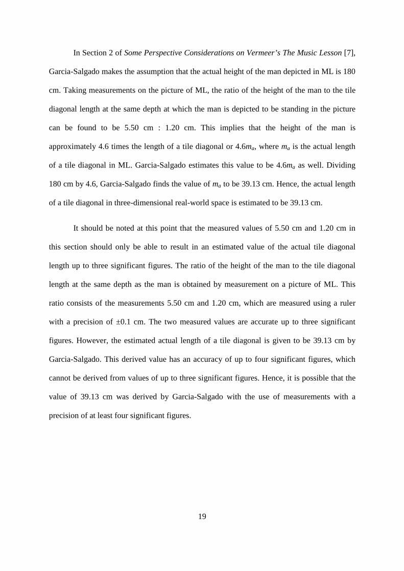
Fig. 8 View of fraction of visible tile diagonal for the tile at the bottom
edge of PP in The Music Lesson
Therefore, adding up the total length of the eight full tile diagonals along a visible
column of ML, 8m, the assumed visible length of the tile at the front wall in ML, 0.5m, and
the estimated visible length of the tile at the bottom edge of ML, 0.9m, we obtain 9.4m as the
total visible depth of the room. The total visible depth of the room is also the distance
between the PP of ML and the front wall.
To find the distance between the PPf of ML and the front wall of ML, we express the
visible depth of the room in terms of the actual tile diagonals, ma. Therefore, the distance
between PPf and the front wall is 9.4ma as expressed in Fig. 7 above.
26
5.1.4 Distance between the Observer and the Front Wall and the Total
Depth of the Room in The Music Lesson
In Section 3 of Modular Perspective and Vermeer’s Room [2], Garcia-Salgado
calculates the distance between the observer point and the front wall in The Music Lesson
(ML). The distance between the observer and the Perspective Plane on the floor (PPf) of ML
is 5ma and the distance between PPf and the front wall is 9.4ma. Therefore, adding up these
two distances, we obtain the distance of the observer point from the front wall of ML as
14.4ma.
In Section 3 of Some Perspective Considerations on Vermeer’s The Music Lesson [7],
Garcia-Salgado states that the total depth of the room in ML is 640 cm. The value of 640 cm
can be calculated in the following manner. The distance of the observer from the front wall is
14.4ma as calculated in the previous paragraph. The distance between the observer and the
Perspective Plane of the back wall (PPbw) of ML is 1.94ma as calculated in Section 5.1.3.
PPbw refers to the picture of ML which is projected onto the assumed back wall position.
Hence, the distance of the observer from the back wall is the distance between the observer
and PPbw of ML, which is 1.94ma. By summing the distance between the observer and the
front wall, 14.4ma, and the distance between the observer and the back wall, 1.94ma, we
obtain the total depth of the room, the distance between the back wall and the front wall, as
16.34ma. The tile diagonal length in real-world space, ma, is 39.13 cm as calculated in Section
5.1.1. Multiplying 16.34 with the absolute length of ma, 39.13 cm, the total depth of the room
is calculated to be 640 cm.
In conclusion, for Section 5.1 of this paper, we have considered ML and discussed the
computations to obtain the absolute distance of the tile diagonal and the following distances

27
in terms of modules: the distance between the observer point and the PPf of ML, the distance
between the observer point and the PPbw of ML, the visible depth of the room, the distance
of the observer point from the front wall and the total depth of the room.
5.2 A Lady Standing at a Virginal
In this section, we will consider A Lady Standing at a Virginal (LSV). Similar to
Section 5.1, we will explore how Garcia-Salgado obtains distances in terms of modules,
where the modules used are the tile diagonals on the bottom edge of the Perspective Plane on
the floor (PPf) of LSV and the Perspective Plane of the back wall (PPbw) of LSV.
Similar to The Music Lesson (ML), in A Lady Standing at the Virginal (LSV), Garcia-
Salgado uses the term “module” to refer to the tile diagonal at the bottom edge of the
Perspective Plane (PP) of LSV, as viewed from the observer point. We denote the actual
arbitrary length, which is not affected by perspective and measured on the bottom edge of the
PP of LSV, as l. We also denote the length of the tile diagonal length at the bottom edge of
the PPf of LSV and at the bottom edge of the PPbw of LSV, as viewed by the observer, as l0
and l0' respectively. We also denote the actual length of the tile diagonal to be la and the
actual length of the tile diagonal on the painting of LSV to be la'. The notations introduced
here will be used for the entire paper.
5.2.1 Relative Positions of the PPf, the PPbw and the Front Wall of A Lady
Standing at a Virginal in terms of Modules
Fig. 9 below shows the side view of the relative positions of the Perspective Plane on
the floor (PPf), the Perspective Plane of the back wall (PPbw) and front wall from the
28
observer point (O). Fig. 9 is drawn based on Fig. 1b in Modular Perspective and Vermeer’s
Room [2] by Garcia-Salgado.
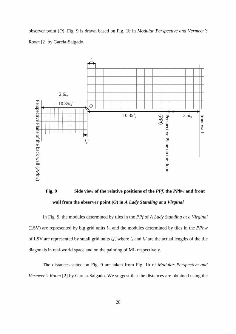
Fig. 9 Side view of the relative positions of the PPf, the PPbw and front
wall from the observer point (O) in A Lady Standing at a Virginal
In Fig. 9, the modules determined by tiles in the PPf of A Lady Standing at a Virginal
(LSV) are represented by big grid units la, and the modules determined by tiles in the PPbw
of LSV are represented by small grid units la', where la and la' are the actual lengths of the tile
diagonals in real-world space and on the painting of ML respectively.
The distances stated on Fig. 9 are taken from Fig. 1b of Modular Perspective and
Vermeer’s Room [2] by Garcia-Salgado. We suggest that the distances are obtained using the
2.6la
= 10.35la'
Perspective Plane of the back wall (PPbw
)
front wall
Perspective Plane on the floor (PPf)
3.5la 10.35la
la'
la
O

29
methods outlined in Sections 5.1 of this paper, which will be explained in the following
paragraphs.
Garcia-Salgado most probably uses an object in LSV as a reference, assumes the
actual length of the object in real-world space and estimates its length in terms of the actual
length of a tile diagonal in LSV, la. Dividing the actual length of the object by its estimated
length in la, the actual length of the tile diagonal in LSV is obtained. We will denote the
actual length of the tile diagonal of LSV as q cm. In other words, la = q cm.
The distance between the central vanishing point and a side vanishing point can be
measured on LSV. The side vanishing points are assumed to be equidistant from the central
vanishing point. Therefore, the distance between the observer point and the PPbw of LSV is
also the distance between the central and side vanishing points. We denote the absolute
distance between the observer point and the PPbw of LSV as r cm.
The length of the tile diagonal on the bottom edge of the picture of LSV can be
measured and we denote this absolute length s cm.
The calculations required to obtain the values stated on Fig. 9 are shown below.
Width of picture of LSV = 1149 pixels = 45.2 cm [9]
Ratio of pixels to cm on the picture of LSV = 1149 pixels : 45.2 cm
Actual length of tile diagonal at bottom edge of the picture of LSV
= s cm (after conversion from pixels to cm using above stated ratio)
cvp-rvp on picture of LSV
= r cm (possibly estimated by Garcia-Salgado)

30
Ratio of la' to cvp-rvp on picture of LSV
= s cm : r cm
Actual length of the tile diagonal at PPf
= la = q cm
Since O-PPf = cvp-rvp, where cvp-rvp is measured in terms of actual tile diagonals
at PPf,
O-PPf = tqsr
=×
O-PPf in terms of actual tile diagonals at PPf = alqt 35.10=
Distance between observer point and PPbw in terms of actual tile diagonals at PPbw
= 10.35la' because the distance between in terms of modules remains the same
regardless of the position of the Perspective Plane (PP) of LSV along the line of
sight in the visual pyramid of LSV.
Ratio of tile diagonal length on PPbw to tile diagonal length on PPf
= la' : la
= s cm : q cm
sq
ll
a
a =′
⇒ qsl
l aa =′
⇒ aa
a lqsl
l 6.235.1035.10 =×=′
Along the left most column of LSV, three full tile diagonals can be counted as the
visible depth of the room. The tile diagonal at the bottom edge of LSV is observed
31
to be about half of a full tile diagonal. Therefore, we assume that the tile diagonal at
the bottom edge of LSV is 0.5l.
Distance between PP and the front wall
= total visible depth of room
= 3l + 0.5l
= 3.5l
⇒ Distance between the PPf and front wall = 3.5la
5.2.2 Distance between the Observer and the Front Wall in A Lady
Standing at a Virginal
In Section 3 of Modular Perspective and Vermeer’s Room [2], Garcia-Salgado
calculates the distance between the observer point and the front wall in A Lady Standing at a
Virginal (LSV). The calculation is the same as that in The Music Lesson (ML) as discussed in
Section 5.1.4 of this paper. For LSV, the distance between the observer and the Perspective
Plane on the floor (PPf) of LSV is 10.35la and the distance between PPf and the front wall is
3.5la. Therefore, summing these distances, we obtain the distance of the observer point from
the front wall of LSV as 13.85la.
To summarise Sections 5.2, we have considered LSV and discussed the calculations
to obtain the following distances in terms of modules stated on Fig 5.2: the distance between
the observer point and the PPf of LSV, the distance between the observer point and the
Perspective Plane of the back wall (PPbw), the visible depth of the room. We also discussed
the calculation of the distance of the observer from the front wall.

32
5.3 Observer Points of The Music Lesson and A Lady Standing at the
Virginal and Side Vanishing Point of A Lady Standing at the Virginal
In Sections 5.1 and 5.2 of this paper, we calculated distances from The Music Lesson
(ML) and A Lady Standing at the Virginal (LSV). In this section, we will explore how
Garcia-Salgado compares the distance between the observer points and the front wall for both
ML and LSV, and calculates the position of the side vanishing point of LSV using the
calculated distances of ML.
5.3.1 Comparing the Distance between the Observer Point and the Front
Wall for The Music Lesson and A Lady Standing at a Virginal
Fig. 10 Observer point of The Music Lesson (OM), observer point of A Lady
Standing at a Virginal (OL), side vanishing point of The Music Lesson (svpM) and side
vanishing point of A Lady Standing at a Virginal (svpL)
1.94ma
= 5ma'
Perspective Plane of the back wall of
(PPbw) in The M
usic Lesson
front wall in
The Music Lesson
Perspective Plane on the floor (PPf) in The M
usic Lesson
0.55ma
ma'
ma
OM OL
svpM
svpL 1.43ma'
33
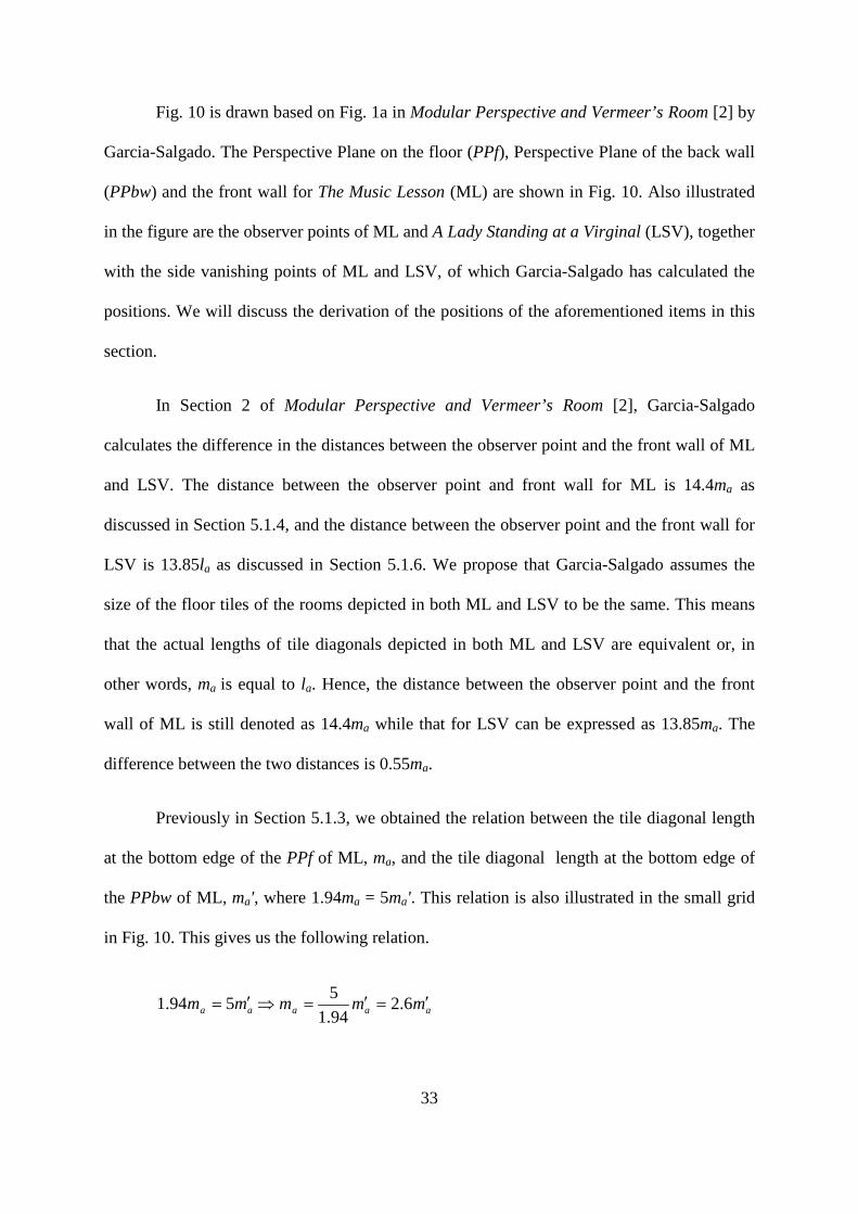
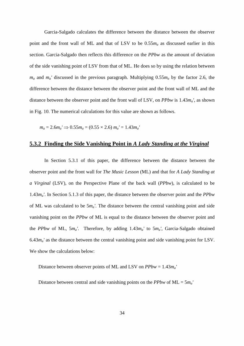
Fig. 10 is drawn based on Fig. 1a in Modular Perspective and Vermeer’s Room [2] by
Garcia-Salgado. The Perspective Plane on the floor (PPf), Perspective Plane of the back wall
(PPbw) and the front wall for The Music Lesson (ML) are shown in Fig. 10. Also illustrated
in the figure are the observer points of ML and A Lady Standing at a Virginal (LSV), together
with the side vanishing points of ML and LSV, of which Garcia-Salgado has calculated the
positions. We will discuss the derivation of the positions of the aforementioned items in this
section.
In Section 2 of Modular Perspective and Vermeer’s Room [2], Garcia-Salgado
calculates the difference in the distances between the observer point and the front wall of ML
and LSV. The distance between the observer point and front wall for ML is 14.4ma as
discussed in Section 5.1.4, and the distance between the observer point and the front wall for
LSV is 13.85la as discussed in Section 5.1.6. We propose that Garcia-Salgado assumes the
size of the floor tiles of the rooms depicted in both ML and LSV to be the same. This means
that the actual lengths of tile diagonals depicted in both ML and LSV are equivalent or, in
other words, ma is equal to la. Hence, the distance between the observer point and the front
wall of ML is still denoted as 14.4ma while that for LSV can be expressed as 13.85ma. The
difference between the two distances is 0.55ma.
Previously in Section 5.1.3, we obtained the relation between the tile diagonal length
at the bottom edge of the PPf of ML, ma, and the tile diagonal length at the bottom edge of
the PPbw of ML, ma', where 1.94ma = 5ma'. This relation is also illustrated in the small grid
in Fig. 10. This gives us the following relation.
aa mm ′= 594.1 aaa mmm ′=′=⇒ 6.294.15
34
Garcia-Salgado calculates the difference between the distance between the observer
point and the front wall of ML and that of LSV to be 0.55ma as discussed earlier in this
section. Garcia-Salgado then reflects this difference on the PPbw as the amount of deviation
of the side vanishing point of LSV from that of ML. He does so by using the relation between
ma and ma' discussed in the previous paragraph. Multiplying 0.55ma by the factor 2.6, the
difference between the distance between the observer point and the front wall of ML and the
distance between the observer point and the front wall of LSV, on PPbw is 1.43ma', as shown
in Fig. 10. The numerical calculations for this value are shown as follows.
ma = 2.6ma' ⇒ 0.55ma = (0.55 × 2.6) ma' = 1.43ma'
5.3.2 Finding the Side Vanishing Point in A Lady Standing at the Virginal
In Section 5.3.1 of this paper, the difference between the distance between the
observer point and the front wall for The Music Lesson (ML) and that for A Lady Standing at
a Virginal (LSV), on the Perspective Plane of the back wall (PPbw), is calculated to be
1.43ma'. In Section 5.1.3 of this paper, the distance between the observer point and the PPbw
of ML was calculated to be 5ma'. The distance between the central vanishing point and side
vanishing point on the PPbw of ML is equal to the distance between the observer point and
the PPbw of ML, 5ma'. Therefore, by adding 1.43ma' to 5ma', Garcia-Salgado obtained
6.43ma' as the distance between the central vanishing point and side vanishing point for LSV.
We show the calculations below:
Distance between observer points of ML and LSV on PPbw = 1.43ma'
Distance between central and side vanishing points on the PPbw of ML = 5ma'
35
Distance between central and side vanishing points of LSV
= 5ma' + 1.43ma' = 6.43ma'
5.4 Trimming the PPbw
In this section, we will explore the effects of trimming the Perspective Plane of the
back wall (PPbw). By trimming, we mean that the picture is cropped all around the periphery
of the picture. As an example, we will consider the PPbw of The Music Lesson (ML). As
calculated in Section 5.1.3, the distance between the observer point and the PPbw of ML is
5.0ma', where ma' is the actual length of the tile diagonal measured at the bottom edge of the
PPbw of ML. The absolute distance between the observer point and the PPbw of ML is 76
cm. The number of visible tiles seen in the picture is 9.4 tiles. Throughout the process of
trimming, the PPbw of ML is fixed to be at its initial position of distance O-PPbw from the
observer point within the visual pyramid. Hence, the absolute distance between the observer
point and the PPbw of ML remains at the value of 76 cm.
An example of trimming is illustrated in Fig. 11a and Fig. 11b below, where the
former represents the PPbw of ML before trimming and the latter represents the PPbw after
trimming. After trimming, the observer would view the tile diagonal at the bottom edge of the
PPbw of ML to be shorter than the initial tile diagonal at the bottom edge. We denote the new
length of the tile diagonal at the bottom edge of the PPbw of ML in Fig. 11b as m1'. The
absolute distance between the observer point and the PPbw of ML remains unchanged
because the PPbw remains at the same depth within the visual pyramid. However, the tile
diagonal chosen as the module has changed. In the visual pyramid, the depth of the new tile
diagonal chosen as the module is greater than that of the initial tile diagonal chosen as the
module. The distance between the central vanishing point and the right vanishing point,

36
expressed in terms of the length of the new tile diagonal, would be the distance between the
observer point and the plane positioned at the same depth as the new tile diagonal. This
distance is equivalent to the distance between the central and right vanishing points in terms
of the new module. Since the new tile diagonal is shorter than the initial one as seen by the
observer, this distance increases in terms of the number of modules. Furthermore, when the
PPbw of ML is trimmed, the number of visible tiles depicted in the PPbw of ML decreases.
The number of visible tiles decreases at the same rate at which the distance between the
observer point and the plane at the same depth as the new tile diagonal increases, in terms of
the number of modules.
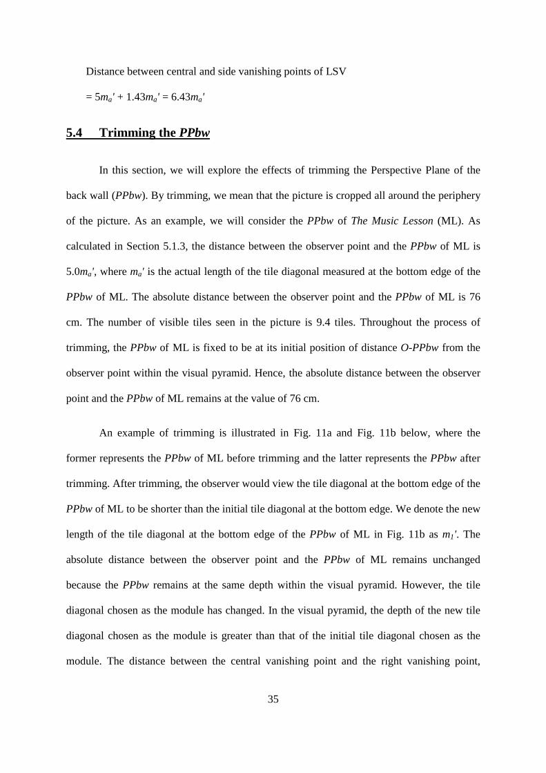
Fig. 11a-11e Trimming the Perspective Plane of the back wall (PPbw)
of The Music Lesson
From Fig. 11a to Fig. 11b shown above, the distance between the central vanishing
point and the right vanishing point increases in terms of number of modules, from 5.0m0' to
Fig. 11a Fig. 11b
Fig. 11c Fig. 11d Fig. 11e
5m0' 5.4m1'
5.9m2' 6.4m3' 9.9m4'
cvpML0 rvpML0
m0' m1'
m2' m3' m4'
9.0m1'
8.5m2' 8.0m3'
8.0m4'
9.4m0'

37
5.4m1'. At the same time, the number of visible tiles decreases from 9.4m0' to 9.0m1'. In terms
of the number of modules, the distance between the observer point and the front wall in the
PPbw of ML remains constant at 14.4 modules. It is noted that Garcia-Salgado makes the
assumption that the side vanishing points are at equal distances from the central vanishing
point, and thus only depicts one side vanishing point for each PPbw in the figures. Three
more stages of trimming are shown in Fig. 11c, Fig. 11d and Fig. 11e.
It may seem contentious that the absolute distance between the central and right
vanishing points remains constant while the value of this distance changes with each
trimming of the PPbw. However, if we distinguish the significance of these two lengths, we
will see that there is no contention. When trimming occurs, the PPbw does not change in
depth. This implies that the distance between the PPbw and the observer remains constant. In
Fig. 11a, the four edges of the initial PPbw will touch the edges of the visually pyramid
defined by itself. This indicates that the depth of the tile diagonal at the bottom of the initial
PPbw is at the same depth as the PPbw in the visual pyramid. When we trim the PPbw and
measure a new tile diagonal to find the length of the new module, the edges of the new PPbw
will not touch the edges of the initial visual pyramid. Consequently, the tile at which the new
measurement is taken will not be at the same depth as the initial tile diagonal taken as the
module. In fact, this new tile diagonal would be at a greater depth or distance away from the
observer than the new PPbw. Hence, when we use the new tile diagonal length to compute
the distance between the PPbw and the observer in terms of tiles, we are in reality finding the
distance between the plane, which has the same depth as the new tile diagonal, and the
observer, rather than the PPbw which has not changed in depth. As a result, the absolute
distance between the PPbw and the observer and the same distance in terms of number of
tiles represent different lengths – the distance between the observer and the PPbw, and the
38
distance between the observer and the plane at the same depth as the new tile diagonal
measured as the new module after trimming. When we consider these two as separate
distances, the contention does not exist.
5.5 The Music Lesson and A Lady Standing at a Virginal
In Section 3 of Modular Perspective and Vermeer’s Room, Garcia-Salgado attempts
to verify whether Vermeer’s paintings The Music Lesson (ML) and A Lady Standing at a
Virginal (LSV) were painted by the artist in the same studio. In this section, we will explicate
the reasoning behind Fig. 3a, Fig. 3b and Fig. 3c in Section 3 of his paper. [2]
5.5.1 Overlaying ML and LSV at the Central Vanishing Point
To begin the verification, Garcia-Salgado depicts ML and LSV such that the central
vanishing points (cvp) of both pictures are overlapped in Fig. 3a of his paper, as shown in
Fig. 12 below. [2] This means that the lines of sight (O-cvp) of ML and LSV are overlaid
such that their individual O positions need not be at the same point in three-dimensional real-
world space. Viewing the outlines of these two images along the overlaid O-cvp lines, ML
and LSV would be overlaid at their individual cvp positions as shown in Fig. 12.

39
Fig. 12 View of the PPbw of The Music Lesson and the PP of A Lady Standing at a
Virginal along their overlapping lines of sight
In the figure, the image of LSV is arbitrarily set to be smaller than that of ML and the
length of the tile diagonal at the bottom edge of LSV, as viewed by the observer, is denoted
as the variable lv. We call this image of LSV the Perspective Plane (PP) of LSV. Garcia-
Salgado’s purpose for setting the PP of LSV to be based on an arbitrary module length lv will
be apparent when we proceed to Fig. 13. Based on a measured value indicated in Fig. 10, the
PP of LSV is 10.35lv away from the observer [2]. Since O-PP = cvp-rvp, the distance
between cvp and rvpLSV for the PP of LSV is 10.35lv, as indicated in Fig. 12 by the shorter
scale. The length of the tile diagonal at the bottom edge of ML, as viewed from the observer
point, is taken to be m0'. Similarly, based on a measured value in Fig. 9, the plane of ML is
5m0' away from the observer when viewed from the observer point, resulting in the distance
between cvp and rvpML for ML to be 5m0', as indicated in Fig. 12 by the longer scale. This
rvpLSV rvpML
5m0' 10.35lv
cvp

40
plane of ML is the Perspective Plane of the back wall (PPbw) of ML because the distance
between cvp and rvpML is 5m0', when viewed from the observer point.
5.5.2 Deriving the Dimensions of the LSV Painting
After depicting the PP of LSV and the PPbw of ML in Fig. 3a of his paper, Garcia-
Salgado depicts the two images with an additional third image in Fig. 3b of his paper, as
illustrated in Fig. 13 below. [2] In Fig. 13, the PP of LSV and the PPbw of ML together with
their corresponding scales and rvp positions are depicted as previously shown in Fig. 12. The
dimensions of the middle-sized plane, which will later be found as the PPbw of LSV, will be
derived in this section.
Fig. 13 View of The Music Lesson and A Lady Standing at a Virginal as depicted
in Fig. 12 with the addition of the PPbw of A Lady Standing at a Virginal
The scale of the PPbw of ML, which is in terms of m0', is used to find the rvpLSV' of
the PPbw of LSV at 6.43m0'. Since the PPbw of LSV occurs 10.35 tile diagonals away from
the observer, 6.43m0' is equivalent to 10.35l0', where l0' is the length of a tile diagonal at the
cvp
rvpLSV rvpML'
c
c'
rvpLSV'

41
bottom edge of the PPbw of LSV as viewed from the observer point. This implies that l0' =
(6.43/10.35) m0'. Using MATLAB, a software for numerical computation, the width of the
PPbw of LSV is measured to be approximately 5.00 tile diagonals or 5.00l0', when the length
of the tile diagonal is measured at the bottom edge of the PPbw of LSV as viewed from the
observer point. Likewise, the width of the PPbw of ML is measured to be approximately 4.27
tile diagonals or 4.27m0', when the length of the tile diagonal is measured at the bottom of the
PPbw of ML as viewed from the observer point. We know that the actual dimensions of ML
are given by 73.3 cm by 64.5 cm [8]. This gives
64.5 cm = 4.27m0' = 4.27 × (10.35/6.43) × l0'
⇒ cml35.1027.443.65.64
0 ××
=′
⇒ width of PPbw of LSV
35.1027.443.65.6400.5
××
×= cm
92.46= cm
We know that the ratio of the height to the width of the PPbw of LSV is 1381 : 1200
[9]. Using this ratio, we may convert the actual width of the LSV to the actual height of the
LSV, and it is found to be 54.00 cm. Hence, we derive the actual dimensions of the LSV
painting to be 54.00 cm by 46.92 cm. This is close to the actual dimensions of the LSV given
to be 51.7 cm by 45.2 cm, which implies that the error of this method in deriving the
dimensions of the PPbw of LSV is up to 4.5%.
The derivation of the dimensions of the PPbw of LSV can also be understood
geometrically. For the PP of LSV, a line c-rvpLSV is drawn from rvpLSV to the centrally
bottommost position, c, of that plane. A line parallel to the aforementioned line is extended
42
from the rvpLSV' of the PPbw of LSV until it reaches a point that has the same horizontal
position as the cvp, and this point is denoted by c'.
The vertical position of c' is the vertical position of the base of the PPbw of LSV.
This is true because a transformation of the PP of LSV to the PPbw of LSV is analogous to
shifting the PP of LSV along the line of sight within the visual pyramid of the LSV, such that
the PP of LSV is scaled proportionately to fit exactly into the initial visual pyramid at all
positions along the line of sight. The PP of LSV would be transformed into the PPbw of LSV
at the position where the size of the plane that fits exactly into the visual pyramid is the same
as that of the PPbw of LSV. This implies that any length between two points in the initial PP
of LSV would be scaled proportionately to map to the corresponding length in the
transformed plane. Hence, if cvp-rvpLSV is transformed to become cvp-rvpLSV' by a certain
scale, cvp-c would be mapped to cvp-c' by the same scale. This would mean that the PP of
LSV is also mapped to the PPbw of LSV by the same scale. Hence, the vertical position of
the base of the PP of LSV, c, would be mapped to the vertical position of the base of the
PPbw of LSV, denoted by c'. From Fig. 13, the ratio of cvp-rvpLSV to cvp-rvpLSV' is
measured to be 4.4 : 9.1. Therefore, the ratio of cvp-c to cvp-c' and consequently that of the
dimensions of the PP of LSV to the dimensions of the PPbw of LSV would be 4.4 : 9.1.
Finally, to derive the dimensions of the PPbw of LSV, we make use of the positions
of cvp, c' and the four corners of the PP of LSV. When the PP of LSV is shifted along the
line of sight within the visual pyramid of the LSV, the direction of each line joining a corner
to cvp as viewed along the line of sight would remain the same. This means that the lines
joining the four corners of the PP of LSV may be extended to reach the corresponding four
corners of the PPbw of LSV. To construct the base of the PPbw of LSV, a horizontal line is
constructed along c' until either side of the line intersects the lines extended from the two

43
lower corners of the PP of LSV. The two resulting intersection points would be the lower left
and right corners of the PPbw of LSV. At each of these two lower corners of the PPbw of
LSV, a vertical line is constructed until it intersects a line extended from an upper corner of
the PP of LSV. In this case, the resulting two intersection points would be the upper left and
right corners of the PPbw of LSV. Joining the four derived corners of the PPbw of LSV, we
determine the PPbw of LSV, indicated in Fig. 13 by the middle-sized frame.
With depictions of the PPbw of LSV and the PPbw of ML in Fig. 13, the actual
dimensions of the PPbw of the LSV can be derived. It is known that the actual dimensions of
the PPbw of ML are 73.3 cm by 64.5 cm [8]. The ratio of the height of the PPbw of LSV to
the height of the PPbw of ML in Fig. 13 is measured to be 4.95 : 6.95. Similarly, the ratio of
the width of the PPbw of LSV to the width of the PPbw of ML in Fig. 13 is measured to be
4.35 : 6.15. Using these two ratios, the actual dimensions of the PPbw of ML can be
converted to the actual dimensions of LSV, which are calculated to be 52.2 cm by 45.6 cm.
This is reasonably close to the actual dimensions of 51.7 cm by 45.2 cm [9] up to an error of
1.0%.
Garcia-Salgado finds the actual dimensions of LSV in this method to be
approximately 51 cm by 45 cm [2], which is also reasonably close to the actual dimensions
up to an error of -1.4%. This means that this method used by Garcia-Salgado in deriving the
dimensions of the PPbw of LSV is most probably accurate. We can infer from this result that
Garcia-Salgado proved that the LSV was painted in the same room as the ML, because the
accuracy of this method relied on the assumption that the paintings were painted in the same
room.
At this juncture, it is noted that there are three possible sets of dimensions of ML as
mentioned in Appendix B, two of which are found from online sources and one from Garcia-
44
Salgado’s paper [7]. In this paper, we only use one set of dimensions. This is because the
second set of dimensions of ML is extracted from a relatively less credible source and we
cannot ascertain that the third set of dimensions, which is stated by Garcia-Salgado, are the
dimensions of the image of ML shown in his paper [7]. The accuracy of the derived
dimensions of LSV may be improved by basing measurements and calculations on the actual
dimensions and image of ML that are used by Garcia-Salgado. This is because the two
methods stated above require the use of the actual dimensions of ML and the width of ML in
terms of the length of the tile diagonal at the bottom edge of ML.
5.5.3 Consistency of the Rooms for ML and LSV
Finally, to verify that the room depicted in A Lady Standing at a Virginal (LSV) is the
same as that depicted in The Music Lesson (ML), Garcia-Salgado attempts a consistency
proof by verifying that an arbitrary point chosen in the room for LSV would map to the same
point in three-dimensional real-world space for ML.
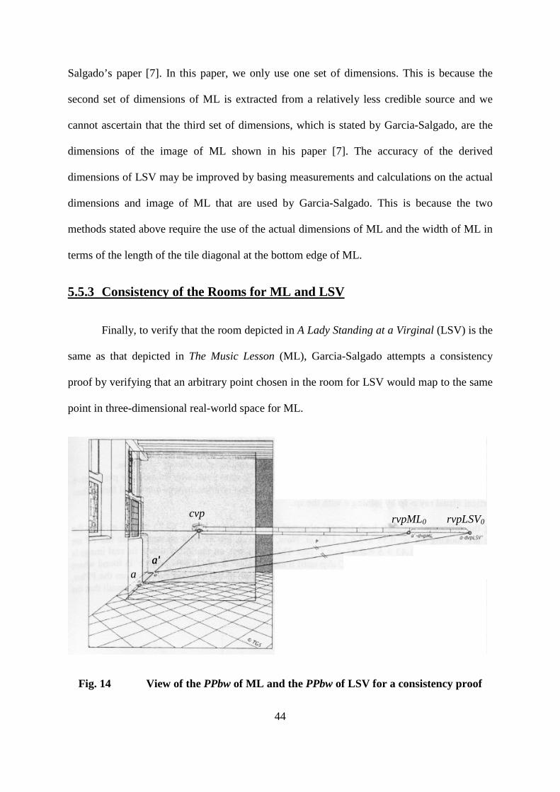
Fig. 14 View of the PPbw of ML and the PPbw of LSV for a consistency proof
cvp
rvpML0 rvpLSV0
a' a' a

45
Referring to Fig. 3c in Section 3 of Garcia-Salgado’s paper, Fig. 14 depicts the PPbw
of ML and the PPbw of LSV from Fig. 13 [2]. To begin the consistency proof, Garcia-
Salgado first chooses an arbitrary point a at the intersection of the floor and the front wall in
the room for LSV. In Section 5.5.2, it is mentioned that Garcia-Salgado estimates the
dimensions of the PPbw of LSV to be 51 cm by 45 cm. The dimensions of the PPbw of ML
used by Garcia-Salgado are 74cm by 63cm [2]. Furthermore, we know from Section 5.3 in
this paper that ML and LSV have different observer positions with respect to the front wall,
provided the two paintings were painted in the same room. Due to the differences in observer
positions and dimensions of the PPbw for ML and LSV, each picture has a different visual
pyramid. Hence, the bottom edges of the Perspective Plane on the floor (PPf) of ML and LSV
have different vertical positions. The height of the PPbw of ML, 74 cm, is greater than that of
the PPbw of LSV, 51 cm. This implies that the bottom edge of the PPbw of ML is below the
bottom edge of the PPbw of LSV, as illustrated in Fig. 14. By taking measurements of the
position of cvp from the base of the PPbw of ML and the PPbw of LSV, we can find that the
position of cvp is 2.60 tile diagonals above the bottom edge of the PPbw of LSV, where the
length of the tile diagonal is measured at the bottom edge of the PPbw of LSV. Similarly, by
measurement, we can find the position of cvp to be 2.75 tile diagonals above the bottom edge
of the PPbw of ML, where the tile diagonal is measured at the bottom edge of ML. These
values of 2.6 tile diagonals and 2.75 tile diagonals also refer to the height of cvp above the
floor depicted in LSV and ML respectively, in terms of the tile diagonal length measured at
any depth in the visual pyramid. Hence, in the consistency proof, point a chosen on LSV is
shifted from the original vertical bottom edge position of Y = -2.60l0' to the new bottom edge
position of Y = -2.75l0' so that point a lies on the floor of ML. This is done to account for the
difference in the visual pyramid of the two pictures due to the different dimensions of the
46
pictures. In Fig. 14, point a is the point that is shifted to the vertical position of Y = -2.75l0',
on the floor of ML.
Previously, in Section 5.3, the actual length of the tile diagonal in ML, ma, and the
actual length of the tile diagonal in LSV, la, were assumed to be equal. Resultantly, the
difference between the observer positions from the front wall for ML and LSV was calculated
to be 0.55ma. By shifting point a by 0.55m0 along the visual ray a-vp, the point a' is obtained
on the intersection of the floor and front wall of ML.
On the scales in Fig. 14, the right vanishing point of ML is denoted as rvpML0 and the
right vanishing point of LSV is denoted as rvpLSV0. The lines a-rvpLSV0 and a'-rvpML0 are
then drawn. Sliding the line a-rvpLSV0 down to intersect the line a'-rvpML0, Garcia-Salgado
finds the lines to be parallel to each other. Hence, he concludes that point a on the
intersection of the floor and front wall of LSV and point a' on the intersection of the floor and
front wall of ML map to the same point in three-dimensional real-world space. This is
because the sliding is akin to shifting one plane along the line of sight in the visual pyramid
to the position of the other plane. Although the visual pyramids for ML and LSV are not the
same, the difference in the visual pyramid due to the size of the picture had been accounted
for. This was achieved through the shifting of the arbitrary point a chosen in LSV to be on
the floor of ML. Additionally, Garcia-Salgado suggests that the consistency proof was carried
out for other pairs of arbitrary points, and each of the pairs of points were found to match to
its corresponding point in three-dimensional real-world space.
For the second part of the consistency proof, Garcia-Salgado compares the heights of
the window sills of ML and LSV. To find the height of the window sill in ML, Garcia-
Salgado first draws a line at an angle of 45° to the floor of ML. This 45° line forms a right
isosceles triangle with the floor and the wall. Hence, at the point where this 45° line intersects
47
the floor, the number of tile diagonals from this point of intersection to the side wall is
counted to be the height of the window sill of ML in terms of tile diagonals. Garcia-Salgado
counts the height of the window sill of ML to be 2.5ma. The same procedure is repeated for
LSV and the height of the window sill of LSV is counted to be 2.3la = 2.3ma by Garcia-
Salgado. The height of the window sills of ML and LSV are estimated to be different. Hence,
Garcia-Salgado comments that the type of the window in the rooms for ML and LSV are not
the same.
Garcia-Salgado concludes from the matching of the pairs of arbitrary points that the
rooms depicted in ML and LSV seem to have the same dimensions and type of floor tiles.
However, the windows in ML and LSV do not match, as discussed above. Therefore, Garcia-
Salgado concludes that the room depicted in ML and LSV may not be the same but the rooms
seem to have similar dimensions.
6 Analysis and Discussion
In this Analysis and Discussion section, we discuss some of the assumptions made by
Garcia-Salgado and suggest improvements to his calculations.
6.1 Analysis on Garcia-Salgado’s Calculations for The Music Lesson
6.1.1 Difference in the Distance between Central Vanishing Point and Side
Vanishing Points
In Section 2 of this paper, we have used the assumption made by Garcia-Salgado that
the set of parallel lines along the tile diagonals converge orthogonally into The Music Lesson
(ML) thus resulting in the side vanishing points situated at equal distance to each side of the
48
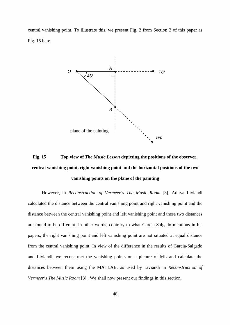
central vanishing point. To illustrate this, we present Fig. 2 from Section 2 of this paper as
Fig. 15 here.
Fig. 15 Top view of The Music Lesson depicting the positions of the observer,
central vanishing point, right vanishing point and the horizontal positions of the two
vanishing points on the plane of the painting
However, in Reconstruction of Vermeer’s The Music Room [3], Aditya Liviandi
calculated the distance between the central vanishing point and right vanishing point and the
distance between the central vanishing point and left vanishing point and these two distances
are found to be different. In other words, contrary to what Garcia-Salgado mentions in his
papers, the right vanishing point and left vanishing point are not situated at equal distance
from the central vanishing point. In view of the difference in the results of Garcia-Salgado
and Liviandi, we reconstruct the vanishing points on a picture of ML and calculate the
distances between them using the MATLAB, as used by Liviandi in Reconstruction of
Vermeer’s The Music Room [3],. We shall now present our findings in this section.
O cvp
rvp plane of the painting
45°
A
B

49
For this section, the coordinate system used for the room in real-world space is such
that the x-axis is parallel to the width of the picture and x-coordinates becomes increasingly
large towards the right side of the picture. The y-axis is parallel to the height of the picture
and y-coordinates become increasingly large towards the bottom of the picture. The z-axis
intersects the observer point and is parallel to the line of sight, with z-coordinates increasing
towards the picture. Each unit on each of the axes of the coordinate system is a pixel.
First we shall explain how we get the coordinates of the vanishing points on the
picture of ML. The central vanishing point is found by using the set of parallel lines along the
tile diagonals which seems to converge orthogonally into the picture. We plot each line on
ML in MATLAB using manually selected coordinates. The best fit line is then found for each
set of coordinates using the MATLAB function polyfit(). The equations of all the lines are
then found using MATLAB. Finally, we use the MATLAB function mldivide() to find the
least square solutions to the set of equations, which is the coordinates of the central vanishing
point on the picture of ML. The same procedure is used to find the left vanishing point and
right vanishing point on the picture of ML. The set of lines along the tile edges that converges
to the left of the picture are used to find the left vanishing point. The set of lines along the tile
edges that converges to the right of the picture are used to find the right vanishing point.
After the coordinates of the vanishing points are obtained, the best fit line is
calculated and this best fit line is the vanishing line of the floor on the picture of ML. We
shall use the term “horizon” to refer to this line. The vanishing points projected on the
horizon of ML are then computed on MATLAB using perpendicular projection. We present
the coordinates of the initial vanishing points on the picture of ML, the equation of the
horizon and the projected vanishing points on the picture of ML below:

50
Initial vanishing points:
Equation of horizon: y = 0.01327x + 1627.8
Projected vanishing points:
The two-dimensional picture is used to find the vanishing points thus there are only x-
coordinates and y-coordinates. The coordinates are in pixels. We will use the coordinates of
the projected vanishing points for the rest of this section.
Now that we have the coordinates of the vanishing points, we shall use the distance
formula to calculate the distance between the central vanishing point and left vanishing point
and the distance between the central vanishing point and right vanishing point. The
calculations of the distances are shown below:
Distance between central and left vanishing points
= √ (1772.1 – 227.0)2 + (1651.4 – 1630.8)2
= 1545.2 pixels
x y
left 227 1631.1
centre 1772.1 1650.7
right 3263.4 1671.4
x y
left 227.0 1630.8
centre 1772.1
1651.4
right 3263.4
1671.2

51
Distance between central and right vanishing points
= √ (3263.4 - 1772.1)2 + (1671.2 - 1651.4)2
= 1491.4 pixels
The distance between the central vanishing point and left vanishing point is 1545.2
pixels. The distance between the central vanishing point and right vanishing point is 1491.4
pixels. Therefore, from our results, the left vanishing point and right vanishing point are not
at equal distances from the central vanishing point. The difference in the distances between
the central vanishing point and each side vanishing point suggests that the set of lines used to
find the central vanishing point are not converging orthogonally into the picture of ML. Since
this set of lines is orthogonal to the front wall, this implies that the picture plane of ML is not
parallel to the front wall. In addition, the vanishing point midway between the left and right
vanishing points would not be a central vanishing point. We call this vanishing point the
middle vanishing point (mvp).
Since the left vanishing point and right vanishing point are not at equal distances to
each side of the central vanishing point, the perpendicular distance of the picture plane from
the observer is not equal to the distance between the middle vanishing point and side
vanishing point. We now proceed to find the perpendicular distance of the picture plane from
the observer using the projected vanishing points we obtain earlier. Let k denote this distance.
The perpendicular distance of the picture plane from the observer point is O-OPP in Fig. 16
below:
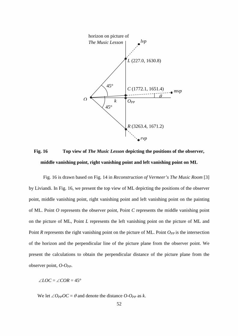
52
Fig. 16 Top view of The Music Lesson depicting the positions of the observer,
middle vanishing point, right vanishing point and left vanishing point on ML
Fig. 16 is drawn based on Fig. 14 in Reconstruction of Vermeer’s The Music Room [3]
by Liviandi. In Fig. 16, we present the top view of ML depicting the positions of the observer
point, middle vanishing point, right vanishing point and left vanishing point on the painting
of ML. Point O represents the observer point, Point C represents the middle vanishing point
on the picture of ML, Point L represents the left vanishing point on the picture of ML and
Point R represents the right vanishing point on the picture of ML. Point OPP is the intersection
of the horizon and the perpendicular line of the picture plane from the observer point. We
present the calculations to obtain the perpendicular distance of the picture plane from the
observer point, O-OPP.
∠LOC = ∠COR = 45°
We let ∠OPPOC = θ and denote the distance O-OPP as k.
horizon on picture of The Music Lesson
O
L (227.0, 1630.8)
C (1772.1, 1651.4)
OPP
R (3263.4, 1671.2)
lvp
mvp
rvp
θ k
45°
45°

53
LC = Distance between mvp and lvp = 1545.2 pixels.
CR = Distance between mvp and rvp = 1491.4 pixels
From Fig. 16, we obtain the following equations:
k tan θ = COPP
k tan (45° + θ) = LOPP
k tan (45° - θ ) = OPPR
From the three equations above, we obtain the following equations:
1545.2 = LC = LOPP - COPP = k (tan (45° + θ) - tan θ)
⇒ k (tan (45° + θ) - tan θ) = 1545.2 (1)
1491.4 = CR = COPP + OPPR = k (tan θ + tan (45° - θ ))
⇒ k (tan θ + tan (45° - θ )) = 1491.4 (2)
Solving equations (1) and (2) in MATLAB, we obtain the following results:
k = 1517.4 pixels and θ = 1.015°
Therefore, the perpendicular distance of the picture plane from the observer
point, O-OPP is 1517.4 pixels.
In conclusion, for Section 6.1 of this paper, we have determined the positions of the
middle vanishing point, left vanishing point and right vanishing point on the picture of ML
and calculated the distances between the vanishing points. Our results show that the distance
between the middle vanishing point and the left vanishing point is not equal to the distance
54
between the middle vanishing point and the right vanishing point. As a result, the
perpendicular distance of the picture plane from the observer point is not equal to the distance
between the middle vanishing point and either of the side vanishing points. We have also
calculated the perpendicular distance between the picture plane and the observer point.
6.1.2 Distance between the Observer Point and the Front Wall of The
Music Lesson
In Section 5.1.4 of this paper, we have discussed how Garcia-Salgado has computed
the the distance between the observer and the front wall, in terms of the number of tile
diagonals on the Perspective Plane on the floor (PPf) of The Music Lesson (ML). The
distance between the observer and the front wall computed by Garcia-Salgado is also based
on the assumption that the side vanishing points are equidistant from the central vanishing
point. We have explored in Section 6.1.1 of this paper that the side vanishing points are not
equidistant from the central vanishing point. Hence, in this Section, we proceed to find the
distance between the observer point and the front wall without using the above-mentioned
assumption made by Garcia-Salgado.
Calculating the distance between the observer and the front wall of ML requires the
perpendicular distance of the PPf of ML which we will calculate here. First, we obtain the tile
diagonal length at the bottom edge of the picture of ML using MATLAB. The length
obtained is in pixels. We then obtain the ratio of pixels to centimetres on the picture of ML,
using the width of the picture of ML in [8]. This ratio is used to convert the tile diagonal
length at the bottom edge of the picture from pixels to centimetres. We also use this ratio to
convert the perpendicular distance of the picture plane from the observer, from pixels to
centimetres. We use the tile diagonal length at the bottom edge of the PPf of ML computed
55
by Garcia-Salgado, 39.13 cm. With the tile diagonal lengths at the bottom edge of PPf and
picture of ML, we have a ratio of tile diagonal length on the PPf of ML to tile diagonal length
on the picture of ML. With this ratio and the perpendicular distance of the picture plane of
ML from the observer point obtained in Section 6.1.1 of this paper, we calculate the
perpendicular distance of the PPf of ML from the observer point.
The tile diagonal length at the bottom edge of the PPf of ML, 39.13 cm, is also the
actual length of the tile diagonal in ML as discussed in Section 4. Dividing the perpendicular
distance between the observer point and the PPf of ML by the actual length of the tile
diagonal in the PPf of ML, we obtain this distance in terms of ma, the tile diagonal at the
bottom edge of the PPf of ML.
The calculations to obtain the perpendicular distance of the PPf from the observer
point are presented below:
Width of picture of ML = 1296 pixels = 64.5 cm
Ratio of pixels to cm on the picture of ML = 1296 pixels : 64.5 cm
Tile diagonal length at bottom edge of the picture of ML
= 303.5 pixels
12965.645.303 ×=
= 15.10 cm
Perpendicular distance of PPf of ML from observer point
= 1517.4 pixels

56
12965.644.1517 ×=
= 75.52 cm
Tile diagonal length at bottom edge of the PPf of ML = 39.13 cm
Ratio of tile diagonal length on PPf of ML to tile diagonal length on picture of ML
= 39.13 : 15.10
Perpendicular distance of PPf of ML from observer point
10.1513.3952.75 ×=
= 195.7 cm
Perpendicular distance of PPf of ML from observer point in terms of ma
am0013.513.397.195==
The distance between the PPf of ML and the front wall obtained by Garcia-Salgado as
discussed in Section 5.1.3 is 9.4ma. Adding this distance to the perpendicular distance of the
picture of ML from the observer point we just calculated, 5.0013ma, we obtain the distance
between the observer point and the front wall of ML to be 14.40ma.
The distance between the observer point and the front wall of ML we just calculated
is the same as that calculated by Garcia-Salgado. We have taken into account that the left
vanishing point and right vanishing point are not at equal distances to each side of the central
vanishing point. However, as computed in Section 6.1.1 of this paper, the angle bounded by
the lines OOPP and OC in Fig. 16, θ = 1.015° which is quite small. Therefore, although the
difference in the distance between the central vanishing point and left vanishing point and the

57
distance between the central vanishing point and right vanishing point affects the accuracy of
the results, the effect is only significant to a small extent.
6.2 The Assumed Height of the Man in The Music Lesson
In Section 5.1.1, it was mentioned that Garcia-Salgado uses the assumption that the
height of the man in The Music Lesson (ML) is 180 cm to calculate the actual length of the
tile diagonal in ML.
ML was painted in the 1600s. In [10], it is stated that the average height of a
Dutchman was 175.26 cm approximately two thousand years ago and the average height
decreased over the 1800 years that followed before the average height of Dutchman increased
again in the mid 1800s to reach the value of about 180 cm [11] today. Consequently, the
average height of the Dutchman in the 1600s would have been estimated to be much lower
than 180 cm, in contrast with the assumption made by Garcia-Salgado. Therefore, the actual
length of the tile diagonal of ML, estimated based on the assumed height of the man in ML,
may be inaccurate. Since the absolute lengths of objects are determined in terms of tile
diagonals in Garcia-Salgado’s papers, the effect of an error in the height of the man in the
picture may be amplified and lead to even greater inaccuracy.
In contrast with Garcia-Salgado, Steadman uses dimensions of relics of objects
depicted in Vermeer’s paintings, rather than an assumed length, as a reference of lengths in
the picture to actual lengths of object in real-world space. As mentioned in Section 2 of this
paper, the maps seen in some of Vermeer’s paintings are real maps that still exist today.
Presently, some of the furniture and instruments depicted in Vermeer’s paintings also exist in
museums. For instance, relics of the lions’ head chair painted in ML are kept in the
Prinsenhof Museum in Delft and in the Rijksmueum in Amsterdam [1]. Since the maps and
58
furniture are located in museums, their dimensions can be measured. To find the actual
lengths of objects depicted in Vermeer’s paintings, Steadman first tries to find the length of a
marble floor tile edge that would result in derived dimensions of maps in ML, which are
close to the actual dimensions of the maps in real-world space. He finds such a length of a
marble floor tile edge to be 29.3 cm.
Using the estimated actual length of a marble tile edge, Steadman calculates the
height, width and depth of the lions’ head chairs in ML to be 108 cm, 42 cm and 42 cm
respectively. These dimensions are close to the true known dimensions of the chair which are
108 cm, 39 cm and 43 cm. Therefore, it seems even more acceptable to use the estimated
length of a marble tile edge to calculate the actual dimensions of objects in ML. Steadman
also proceeds to use this actual length to find the dimensions of other objects in ML and the
dimensions of the room depicted in ML.
Garcia-Salgado calculates the actual length of the tile diagonal in ML based on the
assumed height of the man in ML, which is inaccurate from our discussion in the earlier part
of this section. Instead of assuming the height of the man in ML, an object depicted in ML
with known actual dimensions can be used as a reference to find the actual lengths of other
objects depicted in ML.
7 Conclusion
In this paper, Section 2 and Section 3 introduced readers to the background of the
Perspective Geometry in paintings and the case for Vermeer’s use of the camera obscura in
Sections 2 and 3. Thereafter, the key terms and an understanding of the key concepts used in
Garcia-Salgado papers were presented in Section 4. Following the foundational knowledge
required for understanding Garcia-Salgado’s papers, an understanding of Sections 1 to 3 of

59
Modular Perspective and Vermeer’s Room by Garcia-Salgado was proposed in Section 5.
Finally, in Section 6, assumptions made by Garcia-Salgado were questioned and suggestions
for improvements to the accuracy of the relevant numerical values were suggested.

60
BIBLIOGRAPHY
[1] Steadman, Philip. Vermeer’s Camera: Uncovering the Truth Behind the Masterpieces.
New York: Oxford University Press, 2002.
[2] Garcia-Salgado, Tomas. Guest Lecture. The Bridges Conference: Mathematical
Connections in Art, Music, and Science. Institute of Education, London
Knowledge Lab, London.
[3] Liviandi, Aditya. “Reconstruction of Vermeer’s The Music Room.” 2008. National
University of Singapore. 14 May 2009
<http://www.math.nus.edu.sg/aslaksen/projects/Aditya%20Liviandi%20-
%20Vermeer.pdf>.
[4] Hartley, Richard, and Andrew Zisserman. Multiple View Geometry in Computer
Vision. United Kingdom: Cambridge University Press, 2003.
[5] Dictionary.com. 10 July 2009
<http://dictionary.reference.com/search?q=linear%20perspective&db=luna>.
[6] “The Mystery in the Mirror.” Grand Illusions. 14 May 2009 <http://www.grand-
illusions.com/articles/mystery_in_the_mirror/>.
[7] Garcia-Salgado, Tomas. “Some Perspective Considerations on Vermeer’s The Music
Lesson.” perspectivegeometry.com. No. 1 (2003). 14 May 2009
<http://www.perspectivegeometry.com/>.
[8] Vermeer, Johannes. The Music Lesson. 1662-1664. Buckingham Palace, London.
Essential Vermeer. “Vermeer: The Music Lesson.” 14 May 2009
<http://www.essentialvermeer.com/catalogue/music_lesson.html>.
61
[9] Vermeer, Johannes. A Lady Standing at a Virginal. 1670-1673. National Gallery,
London. Essential Vermeer. “Vermeer: A Lady Standing at a Virginal.” 14 May
2009 <http://www.essentialvermeer.com/catalogue/lady_standing_virginal.html>.
[10] “The Dutch are the World’s Tallest People.” Spry Health. 16 September 2006. 21
May 2009 <http://www.spryhealth.com/12>.
[11] Max, Arthur. “Dutch Reach New Heights.” USA TODAY. 16 September 2006. 21
May 2009 <http://www.usatoday.com/news/offbeat/2006-09-16-dutch-
tall_x.htm>.

62
APPENDICES
Appendix A
List of terms and their corresponding notations as used in this paper and in
the papers by Tomas Garcia-Salgado
Terms (as used in this paper) Notations used in this paper
Notations used by Garcia-Salgado
Observer point O -
Vanishing point vp -
Central vanishing point cvp vp
Left vanishing point lvp vdp, dvp
Right vanishing point rvp vdp, dvp
Middle vanishing point mvp -
Right vanishing point of the Perspective Plane on the floor
of The Music Lesson
rvpML0 dvpML,
ML dvp
Right vanishing point of the Perspective Plane of the back
wall of The Music Lesson
rvpML' ML dvp
Right vanishing point of the Perspective Plane of A Lady
Standing at a Virginal
rvpLSV dvpLSV,
LSV dvp

63
Right vanishing point of the Perspective Plane of the back
wall of A Lady Standing at a Virginal
rvpLSV' LSV' dvp
Distance between any two points A and B A-B -
Perspective Plane PP -
Perspective Plane on the floor PPf PP
Perspective Plane of the back wall PPbw PPbw
The Music Lesson ML ML
Actual length of tile diagonal at the same depth as the
Perspective Plane of The Music Lesson
m m
Length of tile diagonal at the same depth as the
Perspective Plane on the floor of The Music Lesson, as
viewed from the observer point
m0 m
Length of tile diagonal at the same depth as the
Perspective Plane of the back wall of The Music Lesson, as
viewed from the observer point
m0' m'
Actual length of tile diagonal for The Music Lesson ma m
Actual length of tile diagonal on the painting for The
Music Lesson
ma' m
A Lady Standing at a Virginal LSV LSV

64
Actual length of tile diagonal on the Perspective Plane of
A Lady Standing at a Virginal
l m
Length of tile diagonal on the Perspective Plane on the
floor of A Lady Standing at a Virginal, as viewed from the
observer point
l0 m
Length of tile diagonal on the Perspective Plane of the
back wall of A Lady Standing at a Virginal, as viewed
from the observer point
l0' m'
Actual length of tile diagonal for A Lady Standing at a
Virginal
la m
Actual length of tile diagonal on the painting for A Lady
Standing at a Virginal
la' m
Point on the Perspective Plane such that O-OPP is
perpendicular to horizon
OPP -
Horizon - vh

65
Appendix B
The Music Lesson and A Lady Standing at a Virginal
The Music Lesson Version 1
The Music Lesson
Dimensions:
73.3 cm by 64.5 cm (1485 pixels by 1296 pixels)
Source: http://www.essentialvermeer.com/catalogue_xxl/music_xxl.html

66
The Music Lesson Version 2
The Music Lesson
Dimensions: 74.6 cm by 64.1 cm (990 pixels by 870 pixels)
Source: http://en.wikipedia.org/wiki/The_Music_Lesson

67
The Music Lesson used by Tomas Garcia-Salgado
The Music Lesson
Dimensions stated by Garcia-Salgado: 74 cm x 63 cm
Source: “Some Perspective Considerations on Vermeer’s The Music Lesson” by Tomas
Garcia-Salgado

68
There are three different sets of dimensions of The Music Lesson (ML) given by three
sources as shown above. In this paper, the dimensions of ML have been taken to be that of
Version 1 rather than Version 2, because Garcia-Salgado seems to have used a painting of
ML that is cropped similarly to Version 1. The three versions of ML will be compared in the
following paragraphs.
The height of Version 2 of ML is greater than the height of Version 1 of ML. The
fraction of the leftmost tile at the bottom edge of Version 2 of ML that is visible in ML is
smaller than that in Version 1 of ML. The table cloth touches the bottom edge of Version 2 of
ML but not the bottom edge of Version 1 of ML. In addition, a smaller portion of the room
ceiling is depicted in Version 2 than in Version 1 of ML. By these comparisons, the height of
Version 2 of ML would be smaller than the height of Version 1 of ML. However, it should be
noted that the actual dimensions of both versions imply that the height of Version 1 of ML is
smaller than that of Version 2 of ML. This means that either the height of Version 1 of ML or
the height of Version 2 of ML may be incorrect.
The width of Version 2 of ML is shorter than that of Version 1 of ML. In Version 2 of
ML, the porcelain white vase is closer to the left edge of the picture of ML than in Version 1
of ML. Less of the window closer to the observer is also depicted in Version 2 of ML.
From these observations, we may deduce that Version 1 and Version 2 of ML are
cropped differently. Hence, they have different dimensions.
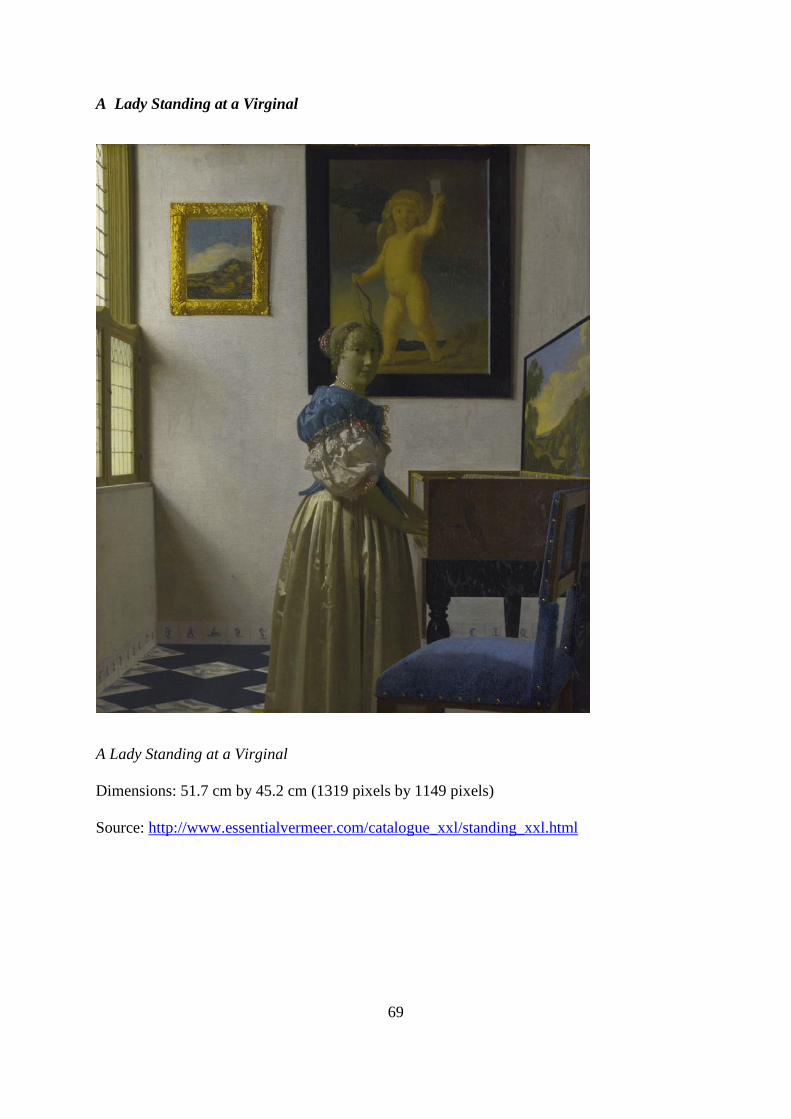
69
A Lady Standing at a Virginal
A Lady Standing at a Virginal
Dimensions: 51.7 cm by 45.2 cm (1319 pixels by 1149 pixels)
Source: http://www.essentialvermeer.com/catalogue_xxl/standing_xxl.html
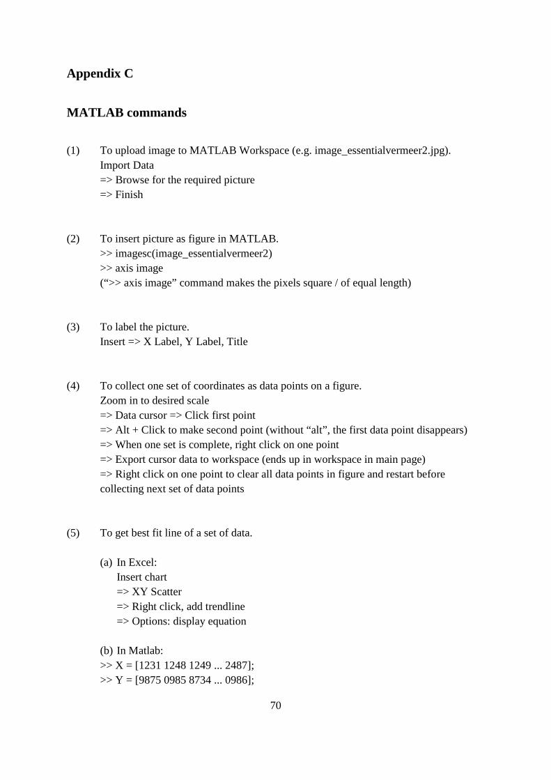
70
Appendix C
MATLAB commands
(1) To upload image to MATLAB Workspace (e.g. image_essentialvermeer2.jpg). Import Data => Browse for the required picture => Finish
(2) To insert picture as figure in MATLAB.
>> imagesc(image_essentialvermeer2) >> axis image (“>> axis image” command makes the pixels square / of equal length)
(3) To label the picture. Insert => X Label, Y Label, Title
(4) To collect one set of coordinates as data points on a figure.
Zoom in to desired scale => Data cursor => Click first point => Alt + Click to make second point (without “alt”, the first data point disappears) => When one set is complete, right click on one point => Export cursor data to workspace (ends up in workspace in main page) => Right click on one point to clear all data points in figure and restart before collecting next set of data points
(5) To get best fit line of a set of data.
(a) In Excel:
Insert chart => XY Scatter => Right click, add trendline => Options: display equation
(b) In Matlab: >> X = [1231 1248 1249 ... 2487]; >> Y = [9875 0985 8734 ... 0986];

71
>> polyfit(X,Y,1) (Use 1 in “polyfit” command because we want a line, which is a polynomial of degree 1) Example of Result: p_r1 = 1.0e+03 * -0.0005 3.0841 Means Y= (1.0e+03) (-0.0005)X + (1.0e+03)( 3.0841) = -0.5X+3084.1
(6) To solve for intersection points (vanishing points).
Y = mX + c => -mX + Y = c Use ‘\’ or ‘mldivide’ to solve x in Ax=B, where A consists coefficients, -m, of X and Y, and B consists values of c (each row of values in A and B is from each line) (a) To solve for left vanishing point, L1 = 0.7878X+1458.7 L2 = 0.6261X +1484.5 L3 = 0.5178X +1505.5 L4 = 0.4364X +1529 L5 = 0.3754X +1549.9 L6 = 0.3321X +1560.7 >> A=[-0.7878 1; -0.6261 1; -0.5178 1; -0.4364 1; -0.3754 1; -0.3321 1] >> B=[1458.7; 1484.5; 1505.5; 1529; 1549.9; 1560.7] >> x=A\B (b) To solve for central vanishing point, C1 = -0.8878X +3230.2 C2 = -1.0735X +3553.3 C3 = -1.3692X +4066 C4 = -1.7757X +4801.2 C5 = -2.6458X +6340.5 C6 = -5.1042X +10696 >> A=[0.8878 1; 1.0735 1; 1.3692 1; 1.7757 1; 2.6458 1; 5.1042 1] >> B=[3230.2; 3553.3; 4066; 4801.2; 6340.5; 10696] >> x=A\B
(c) To solve for right vanishing point, R1 = -0.2324X+2426.3 R2 = -0.2547X+2500.1 R3 = -0.2841X+2593.6 R4 = -0.3081X+2689.9 R5 = -0.3577X+2843 R6 = -0.4203X+3036.5 >> A=[0.2324 1; 0.2547 1; 0.28411; 0.3081 1; 0.3577 1; 0.42031] >> B=[2426.3; 2500.1; 2593.6; 2689.9; 2843; 3036.5]
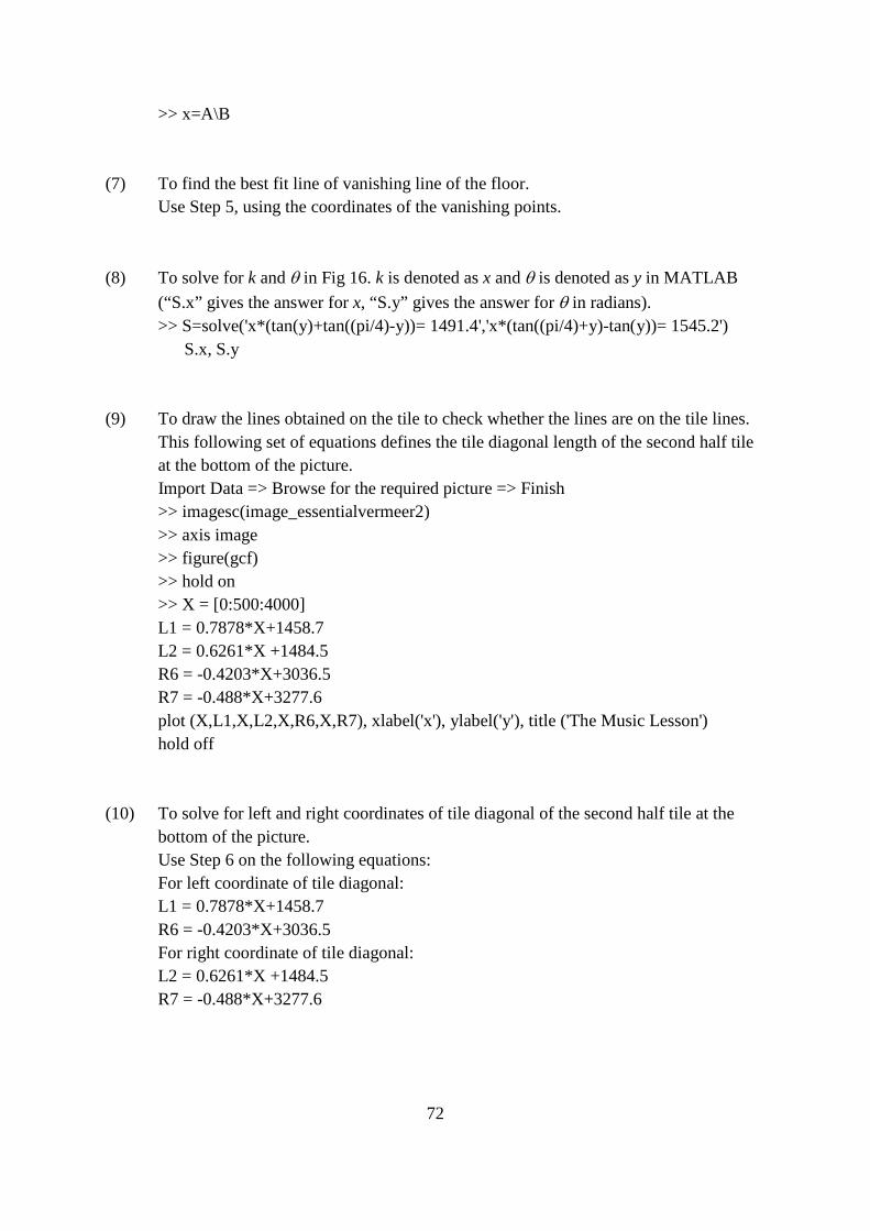
72
>> x=A\B (7) To find the best fit line of vanishing line of the floor.
Use Step 5, using the coordinates of the vanishing points. (8) To solve for k and θ in Fig 16. k is denoted as x and θ is denoted as y in MATLAB
(“S.x” gives the answer for x, “S.y” gives the answer for θ in radians). >> S=solve('x*(tan(y)+tan((pi/4)-y))= 1491.4','x*(tan((pi/4)+y)-tan(y))= 1545.2') S.x, S.y
(9) To draw the lines obtained on the tile to check whether the lines are on the tile lines.
This following set of equations defines the tile diagonal length of the second half tile at the bottom of the picture.
Import Data => Browse for the required picture => Finish >> imagesc(image_essentialvermeer2) >> axis image >> figure(gcf) >> hold on >> X = [0:500:4000] L1 = 0.7878*X+1458.7 L2 = 0.6261*X +1484.5 R6 = -0.4203*X+3036.5 R7 = -0.488*X+3277.6 plot (X,L1,X,L2,X,R6,X,R7), xlabel('x'), ylabel('y'), title ('The Music Lesson') hold off
(10) To solve for left and right coordinates of tile diagonal of the second half tile at the
bottom of the picture. Use Step 6 on the following equations: For left coordinate of tile diagonal: L1 = 0.7878*X+1458.7 R6 = -0.4203*X+3036.5 For right coordinate of tile diagonal: L2 = 0.6261*X +1484.5 R7 = -0.488*X+3277.6
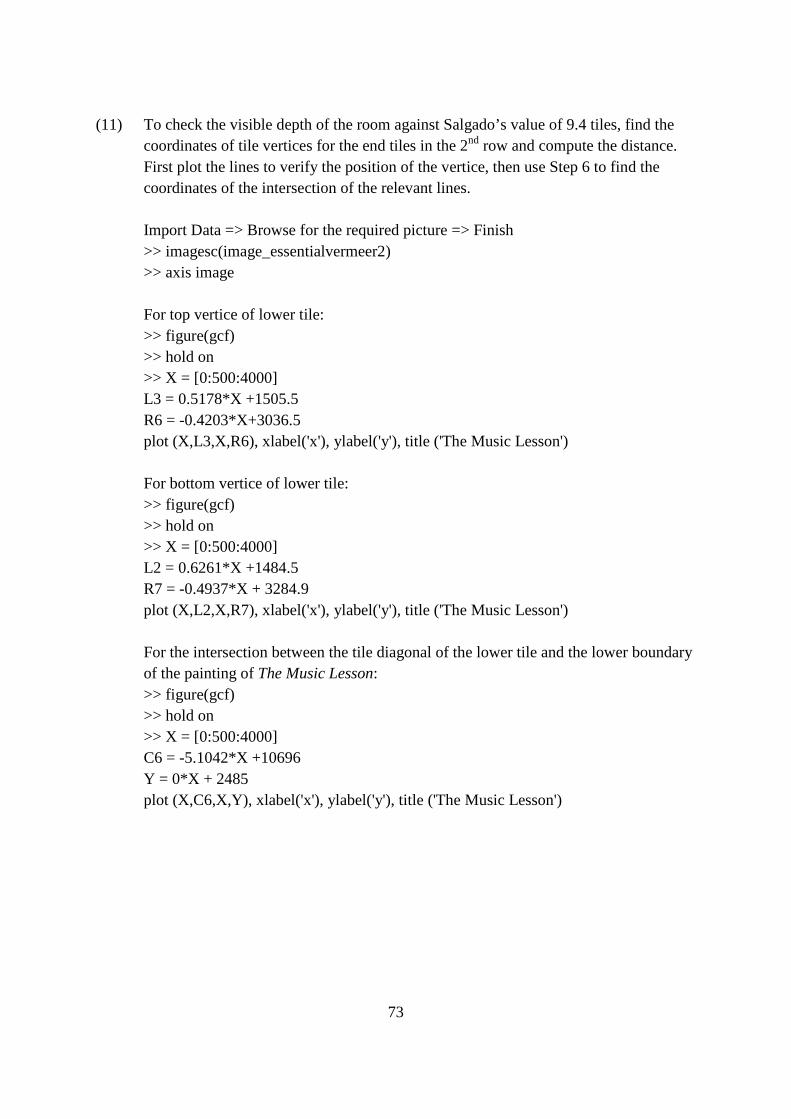
73
(11) To check the visible depth of the room against Salgado’s value of 9.4 tiles, find the
coordinates of tile vertices for the end tiles in the 2nd row and compute the distance. First plot the lines to verify the position of the vertice, then use Step 6 to find the coordinates of the intersection of the relevant lines. Import Data => Browse for the required picture => Finish >> imagesc(image_essentialvermeer2) >> axis image
For top vertice of lower tile: >> figure(gcf) >> hold on >> X = [0:500:4000] L3 = 0.5178*X +1505.5 R6 = -0.4203*X+3036.5 plot (X,L3,X,R6), xlabel('x'), ylabel('y'), title ('The Music Lesson') For bottom vertice of lower tile: >> figure(gcf) >> hold on >> X = [0:500:4000] L2 = 0.6261*X +1484.5 R7 = -0.4937*X + 3284.9 plot (X,L2,X,R7), xlabel('x'), ylabel('y'), title ('The Music Lesson')
For the intersection between the tile diagonal of the lower tile and the lower boundary of the painting of The Music Lesson: >> figure(gcf) >> hold on >> X = [0:500:4000] C6 = -5.1042*X +10696 Y = 0*X + 2485 plot (X,C6,X,Y), xlabel('x'), ylabel('y'), title ('The Music Lesson')