the lm.3 - the new era of efficient energy input … la metallurgia italiana - n. 7/8 2016 electric...
TRANSCRIPT

La Metallurgia Italiana - n. 7/8 2016 5
Forno elettrico
INTRODUCTIONThe steelmaking process is one of the most energy intensive production processes. Therefore all steelmakers focus primarily on energy cost optimisation. As shown in Fig. 1 a large amount of the scrap-to-billet costs are energy costs in form of electricity, gas, and oxygen in the BSW steel plant.
Fig. 1 - Conversion cost distribution at BSW for the steel plant
Electric steelmaking plants use primarily electrical energy followed by fossil energy in form of gas and oxygen. More than 70 % of the energy input of an electric steelmaking plant consists of electrical energy. Gas as a second source for energy is used not only in the EAF but also in the refractory bay, the ladle shop, and at the casting machines for preheating tundishes and torch cutting. Together with the optimization potential of new and modern drives, gas recuperation at burners and other possibilities for the auxiliary power input, currently cost optimization focuses on utilizing the cheapest energy mix for a steelmaking shop.
The LM.3 - the new era of efficient energy input optimization in the EAF
A. Opfermann, F. Goekce, K. Libera, A. Grosse
The energy costs for the production of steel have a large influence on the final conversion costs. The optimization of the furnace operation aims for the usage of the highest amount of the cheapest energy source. But even the high powered furnaces run with the same burner powers as during the last 20 to 30 years, in most cases between 2-5 MW per burner. But this power limitation leads to a much smaller total power of the EAF during melting than during refining; this stage is characterized by an efficient flat bath operation with a high amount of multipoint-oxygen injection. Therefore the idea for the Tiltable-VLB was born and started with success. The mechanical movements as tried several times in history give the possibility of an increase in power without destroying the refractory or oxidizing the scrap. Now the LM.3 offers the additional possibility of installing a powerful movable burner in the door tunnel. More than 6 MW are possible, even as a standalone tool the chemical energy input can be increased easily and without any pilot flame gas consumption.
KEywORDs: EAF - ENERGY COST - CHEMICAL ENERGY - TILTABLE INJECTOR - BURNER OPERATION-LM 3
Andreas Opfermann, Fatih Goekce, Klaus Libera, Alexander Grosse
Badische Stahl-Engineering GmbH, Germany
La Metallurgia Italiana - n. 7/8 20166
Electric arc furnaceSince the EAF is the most energy intensive equipment in an electrical steelmaking shop, the energy input mix optimisation plays a key role for the energy cost optimisation.Nowadays modern EAFs are equipped with high specific installed transformer powers up to 1 MW/ttap weight with a remarkably high rated tap size of above 150 t/heat. The main energy input of
modern EAFs is supplied through the electrical arc, which is additionally supported by sidewall and door oxygen injection, only 5-10% of the total energy is introduced by gas (see Tab. 1). On the other hand, small furnaces in foundries or at special steelmakers are not equipped with burners or other tools
UHP-EAF Low to medium powered EAF
Inputs
Electrical Energy 50-60% 75-85%
Burners 5-10%
Chemical reactions 30-40% 15-25%
Tab. 1 - Energy input distribution in arc furnaces (modern furnace on the left, old style or foundry furnace on the right) [1]
During a heat the following energy inputs can be utilised:
1. Electrical energy by the electrodes in the furnace during melting and refining
2. Burner energy by gas or oil combined with oxygen during melting
3. Refining oxygen for exothermic reactions.
HOw TO FURTHER IMPROVE AND HOw TO RUN THE CHEAPEsT ENERGy MIX?
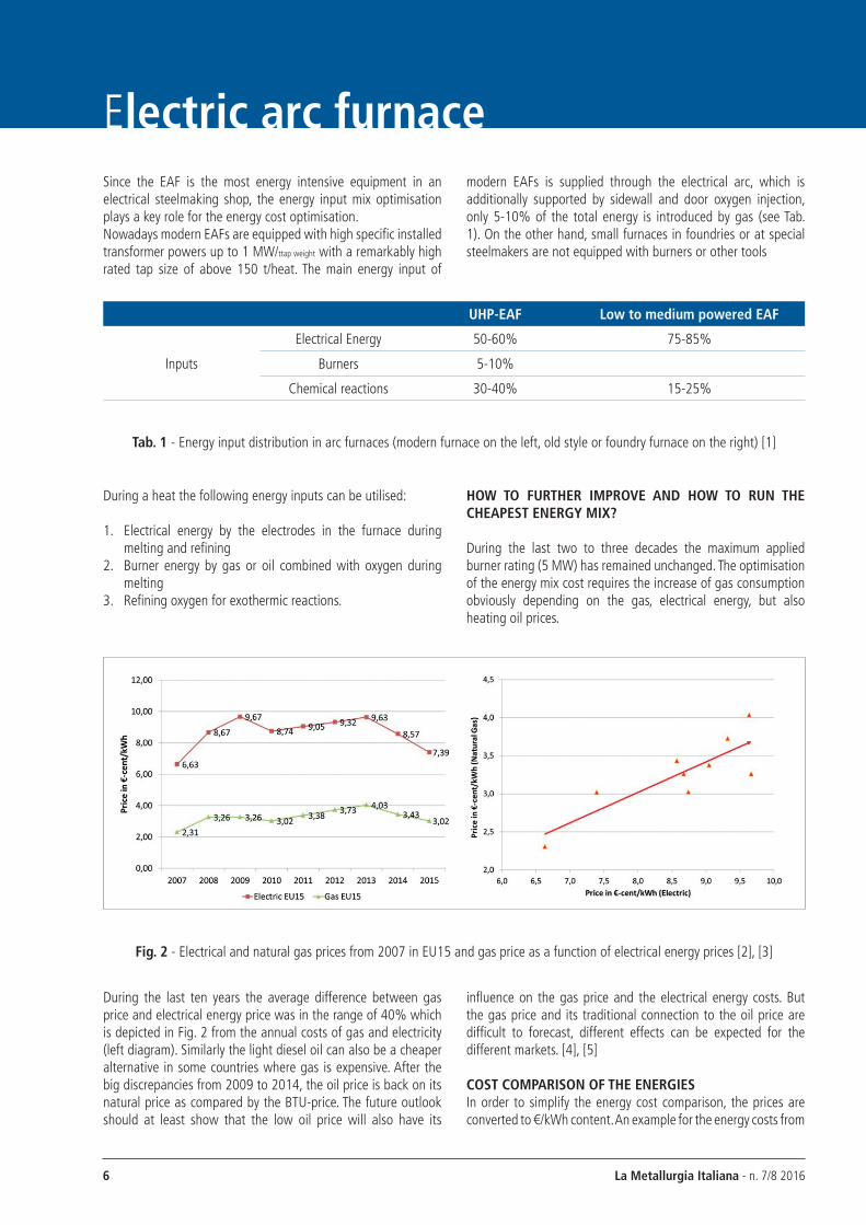
During the last two to three decades the maximum applied burner rating (5 MW) has remained unchanged. The optimisation of the energy mix cost requires the increase of gas consumption obviously depending on the gas, electrical energy, but also heating oil prices.
Fig. 2 - Electrical and natural gas prices from 2007 in EU15 and gas price as a function of electrical energy prices [2], [3]
During the last ten years the average difference between gas price and electrical energy price was in the range of 40% which is depicted in Fig. 2 from the annual costs of gas and electricity (left diagram). Similarly the light diesel oil can also be a cheaper alternative in some countries where gas is expensive. After the big discrepancies from 2009 to 2014, the oil price is back on its natural price as compared by the BTU-price. The future outlook should at least show that the low oil price will also have its
influence on the gas price and the electrical energy costs. But the gas price and its traditional connection to the oil price are difficult to forecast, different effects can be expected for the different markets. [4], [5]
COsT COMPARIsON OF THE ENERGIEsIn order to simplify the energy cost comparison, the prices are converted to €/kWh content. An example for the energy costs from

La Metallurgia Italiana - n. 7/8 2016 7
Forno elettricodifferent sources for three different countries namely Germany, USA, and Russia is shown in Errore. L'origine riferimento non è stata trovata.. In this diagram the specific cost per kWh is shown for the different energy sources as the gas input with oxygen as the base in comparison to the oxygen injection and reaction to carbon-monoxide, and the electrical energy.
Fig. 3 - Comparison of energy prices of different sources for the EAF for three different countries as example
In this comparison the energy yield of the burners is reaching usually approx. 70%; 7 kWh/Nm3 are generated by the stoichiometric reaction of natural gas with oxygen; this is calculated as the base [6].The oxygen reaction reaches in lancing mode approx. 3,5 kWh/Nm3 which is taken into consideration for the price per kWh. This value is given by the combined reaction of oxygen with carbon and iron oxidation (6,6 kWh/Nm3 of oxygen). Iron losses caused by oxygen injection need to be compensated by carbon injection. The iron oxide is reduced back to iron with carbon which is an endothermic reaction. This reduction energy reduces of course the final energy supplied through oxygen injection. The electrical energy cost is considered along with the consumed electrode cost. As depicted in Fig. 3 the price for the gas energy is the lowest in these three cases. The oxygen itself has a low price, but it needs fuel. This fuel has to be added to the oxygen input; the resulting energy by the burning to CO is low as shown later on.
POwER INPUT DURING MELTING AND REFININGAn additional task for improving the chemical energy during melting is given by the energy input share of melting and refining: The limited burner capacity leads to a total power input which is far beyond the refining power, although the melting time needs approx. 60% of the total PON-time. The recommended burner powers are given with 0,133 MW/tcapacity, the range can be found from 30 kWh/t (for eliminating cold spots) to 55-90 kWh/t (for low powered furnaces).[6]EAF side wall burners are usually operated with 3,5-4 MW each in the melting cycle. Depending on the furnace diameter and
construction; the number of installed burners may vary from 3 - 5 pieces, i.e. 14-20 MW in total additional melting power only. On the other hand additional power through the oxygen injection by the side wall and door injection units can produce an additional power input of up to 30 MW which is equivalent to 10.000 Nm³/h oxygen flow rate during refining (3,5 kWh/Nm³ oxygen of chemical reactions). This total power increase by the burner in melting is by far lower than the power introduced by the lancing oxygen in refining: As a result an energy input gap between the melting and refining exists, which needs to be taken into account. Input shares of the power input for different phases are shown in Fig. 4 for BSW-EAFs. It can be clearly seen that the power input share during melting is approx. 30% lower than during refining. In this picture even the lance manipulator is counted by 12 MW. But, and this is obvious, this oxygen is reacting for post combustion but also burning iron of the scrap.
Fig. 4 - Melting and refining power input at BSW
INFLUENCEs OF CARBON DURING REFININGElectrical energy consumption can be improved by replacing the electrical energy with chemical energy. Replacement of electrical energy can be applied either by accelerating the melting with chemical energy input or adding additional energy in refining. The latter can be performed by carbon input because the increase in oxygen input only is leading to an over-oxidation of the steel melt, an increase in FeO in the slag, and decrease of the yield. Additionally refractory wear is increased by the FeO rich slag erosion. Carbon is an unavoidable metallurgical material which acts as a reducing agent, an alloying element, and also as an important energy carrier. It is the cheapest energy carrier used in steelmaking. Carbon oxidation to carbon monoxide gives 2,73 kWh/Nm³oxygen. This is a lower value than created by the simultaneous oxidation of alloys from scrap.[7]. If additional carbon is used to increase the energy input, additional 0,6 kWh/t/kgcarbon is required for carbon dissolution in the bath [8]. Furthermore additional lime is required to neutralize the ash.

La Metallurgia Italiana - n. 7/8 20168
Electric arc furnace
Fig. 5 - FeO-content of slag as function of the carbon content [1]
Tests have been performed for the influence of carbon with constant oxygen injection on other KPIs. Background was the fact that the over-oxidation leads to lower yield due to the oxidation of iron. This effect is shown in literature as example in Fig. 5. This effect can be clearly found in the annual and monthly data of BSW as shown in Fig. 6. The increase of losses by running to lower carbon contents is clearly visible.
Fig. 6 - Yield from metallic input to billet as function of the carbon content
The influence on the energy consumption at the BSW plant is shown in Fig. 7. It clearly shows that the kWh-consumption per ton of billet decreases if oxygen is reduced and carbon is increased. Other positive aspects on consumptions of alloys have been found additionally and have been published already [9].
Fig. 7 - Energy consumption as function of the carbon content
The aim for increasing the oxygen for further decrease of the energy consumption would require a strict increase in carbon to generate heat on the one hand; on the other hand the yield loss
by the oxidation of iron has to be avoided. But the result of the energy consumption of approx. 3,5 kWh/Nm3 is reached by the mixture of the reaction of iron and carbon:
C + ½ O2 = CO with a heat input of 2,73 kWh/Nm3 of oxygen (1)
Fe + ½ O2 = FeO with a heat input of 6,58 kWh/Nm3 of oxygen (2)

La Metallurgia Italiana - n. 7/8 2016 9
Forno elettrico
INFLUENCE OF INCREAsING THE GAs CONsUMPTION IN THE FURNACEBurner power increase targets to improve and accelerate melting down of charged scrap. Two customer experiences are shown in the following part within the typical limits of the fixed burner installations. In both cases the power of the existing VLB installation was increased by 33% and 43% (1,8 to 2,4 MW, 2,8 to 4 MW) during melting.
Fig. 9 - Improvement by increasing the gas input
The melting of scrap by burner and chemical energy only was performed in laboratory scale furnaces as example in England (FOS-process) in the 1960s or in Japan in NSR-process; but the control of the heating especially in the flat bath and also the yield loss have stopped these processes for industrial scale [11]. However, the aim for reducing the electrical energy consumption especially during melting is still given.An example for higher gas consumption is shown in Fig. 9 for a BSE-system at a customer’s furnace. In this case the scrap is pre-molten with burner only and therefore the gas consumption is higher than usual in the EAF. As to be seen the burners are working with an efficiency which is at the theoretical value. This is found because during this time the suction is reduced and losses are at a minimum. But as to be seen later on, also during melting a higher efficiency is reached, higher than in literature [12].The aim is the increase in the melting power; this long period of unstable arc and cold spots in the furnace is minimized by high power burner flames with variable directions to avoid the overheating and oxidation of scrap and fast melting till the centre of the furnace by the low burner inclination. Melting is the only phase where a higher burner power can be introduced during a heat cycle. Additional energy is given by the higher gas input but also extends the flame length, as shown for example in Errore. L'origine riferimento non è stata trovata.. It is clearly visible that a flame with a higher power and therefore a higher flowrate creates a longer flame. In these pictures the flame direction is shown for the Tiltable-VLB of BSE with a direction of 20° during melting.
The value of an oxygen-carbon-reaction of 70-80% is found in several studies/references, i.e. 20-30% of oxygen is reacting with iron [1]. To avoid an iron loss by increasing the oxygen injection the carbon addition has to be increased; but this addition must be solved in the steel (charge carbon) or slag (injected carbon) to
reduce the FeO. And this reaction is naturally taking energy again, as can be seen in Fig. 8. The total resulting energy of additional carbon with additional oxygen is therefore low, experiences of only 2 kWh/Nm3 of oxygen can be found.
Fig. 8 - Energies for the reduction (with carbon) and oxidation with oxygen [10]

La Metallurgia Italiana - n. 7/8 201610
Electric arc furnace
Fig. 10 - Change of the flame length as function of the flame-power and flame prolonging by increasing the power
Tests have been performed to see the effect of increasing the flame power. In the first test a 50 t furnace was operated with four VLBs with 1,8 MW first, then with 2,4 MW. The furnace was charged with three buckets. The result is shown in Fig. 11. Experienced was a large step forward in the direction of the energy consumption but also the flame shape and energy distribution changed.
Fig. 11 - Improvement by increasing the chemical burner power from 1,8 to 2,4 MW
By increasing power the flame penetrated the scrap deeper and the heat was working more efficiently in the scrap. As to be seen in the graph the efficiency of the increase in power reached approx. 10 kWh/Nm3/tscrap (1,6 Nm3/t gas increase for 16 kWh).
Fig. 12 - Improvement by increasing the chemical burner power from 2,8 to 4 MW
The yield remained unchanged; no further yield loss was reported. These results are close to the theoretical value of the natural gas energy content.Nevertheless it has also been found in the next trials, that the burner power increment brought higher energy savings than the theoretical energy content of the natural gas: In this case the furnace (100 t with scrap preheating of the 1st bucket) was running with four VLBs with 2,8 MW each, i.e. a total chemical melting power of 11,2 MW. Burner power increased to 4 MW each VLB, i.e. a melting power of 16 MW. Also in this case the flame length was increased and the heat is penetrating deeper in the scrap; resulting in an energy decrease of even 11 kWh/tscrap with a gas consumption increase of only 0,5 Nm3/t, i.e. a decrease of electrical energy consumption by 16 kWh/Nm3 of gas. The yield was not influenced; the metallurgical oxygen was also in the same range, but 2 t more scrap have been charged, which has always an additional positive effect on the EAF-operation form BSW's experience. The total energy influence of the gas recalculated for different operational pattern leads to varying gas consumptions as to be seen in Fig. 13; in this case the metallurgical oxygen was added on the electrical consumption and the graph shows the pure gas variation and its influence.
Fig. 13 - Decrease in electrical energy larger than theoretical gas-energy-input
Also here it can be seen that the gas has a large influence and the energy input is efficient. The high value reached is of course also influenced by factors which are following the fast melting:

La Metallurgia Italiana - n. 7/8 2016 11
Forno elettrico- The more homogeneous and faster the melting, the earlier
the flat bath phase is reached. The arc is covered and stable, the energy input high
- The liquid bath in the hearth of the furnace has lower losses than scrap in contact with off gas and water cooling equipment. Therefore the liquid bath formation should be accelerated.
- The longer the flame is, the deeper the flame can penetrate the scrap and work from outside while the arc is melting from centre. The longer the flame the more volume of scrap can be heated before the hot gas is leaving upwards to the 5th hole.
- The early back-charging leads to a decrease of energy consumption. Over-melting the bath because of solid scrap in the cold areas leads to overheating of the bath without covered arc (to melt the sidewalls). This leads to losses and refractory wear. At BSW a difference of 8-20 kWh/tbillet was found between earlier and late charged back-charging practices [13], also in the described furnace the 2nd bucket was charged earlier (10.500 kWh instead of 12.000 kWh, i.e. 166 kWh/tscrap instead 190 kWh/tscrap) on the preheated 1st bucket.
- Scrap cutting can start earlier without the danger of backfiring due to the high power input of the burners
The aim is given therefore: Increasing the melting power by burners leads to a total process improvement due to several causes:1. The installation of burners with high power and flames
reaching deeply inside the scrap leads to an increase in melting homogeneity and efficiency.
2. The increase in refining power by further oxygen injection is not helping the long and inhomogeneous melting process.
The problem with the increase in burner power is known [11]: Burners, or “multi-injection-tools” as used today, are mounted approx. 500 mm above the bath in the sidewall and work with an angle of 40°-50° towards the bath to be able to inject the lancing oxygen during refining also. The angle is kept and the burners work with low kinetic energy. The heat transfer of the burners with fuel and oxygen is made mainly by convection, due to the actual low power the speed of the flames is also reduced in the scrap pile. The heat transfer by convection is defined by Newton’s law:
Q=α × F×(tW−tFL) (3)
This means that the temperature difference between the flames and the scrap (tW-tFl) defines the efficiency by a high heat transfer. The hotter the scrap gets, the lower is the heat transfer. The burner flame has to get cold scrap to work efficiently; the fixed installation leads to a small reaction area and therefore a fast overheating of the scrap in the vicinity of the flame. Therefore the efficiency decreases.But this is not the only cause for the lowering efficiency and the limit in power: If the scrap reaches 1400-1450°C, oxidation rate of the scrap rises sharply: The products of the fuel combustion are reduced to CO and H2 and the scrap is oxidized.
CO2 (H2O) + Fe = FeO + CO (H2) (4)
Hence improved chemical energy input during melting must focus on preheating the scrap without excess heating in the area of the oxidation; the higher the power the faster with a fixed operational direction of the flame the scrap in this area gets too hot and oxidation occurs. The flame has therefore to move if the scrap is moving too slowly; the flame must look for fresh scrap to heat.
Fig. 14 - Burner (3) mounted on a lance manipulator [11]
Tests for moving with the scrap have been performed through the door and from the sidewall and roof. The first example is shown in Fig. 25 - Burner (3) mounted on a lance manipulator [11]; in this case a burner was mounted on a lance manipulator and it was used for melting the scrap in a 65t furnace with 35 MW electrical power input in Israel. And running with success: The burner was operated with liquid fuel and a power of 12-15 MW; by this operation during melting the electrical energy consumption was lowered by more than 5% [11]. In this case this manipulator was used instead of several side wall tools.
This is also to be seen in the BSE-customer’s furnaces as described. From this knowledge the aim for the future chemical energy input can be defined:1. The power increase of the burners only works, if the possibility
of reaching “cold” scrap is given; a fixed burner installation does not work with high efficiency, especially if the flame is short, the melting is only performed close to the wall. The burner melts a hole and afterwards the efficiency can drop.
2. The power increase as tested by multi-purpose-sidewall-tools does show additional problems with increased refractory wear: The distance to the wall is too small, the flame burns the bricks; as to be found at installations a certain distance to the bricks is needed. Tests and measurements have been performed and the minimum distance can be kept by the tilting of the VLB during melting.

La Metallurgia Italiana - n. 7/8 201612
Electric arc furnaceThe T-VLBs are running with success, an example for a performance is shown in Fig. 15. The increase in gas by 0,9 Nm3/t leads in combination with a further optimization of the chemical
energy system also here to a remarkable decrease of electrical consumption by 17 kWh/t.
Fig. 15 - T-VLBs in a shaft furnace
The high power of the VLBs in combination with the optimization possibilities leads to the improvement of the melting process without harming the yield as example.This high efficiency of the increase of melting power from the sidewall requires also improving the melting phase by additional non-oxidizing power input through the slag door.
THE NEw CONCEPT FOR THE sIDEwALL INsTALLATION AND THE OPTIMIZATION By THE NEw LM.3As to be seen an improved burner operation leads to a decrease of
energy consumption; productivity can be improved and conversion costs can be reduced. So the aim should be a high power addition by chemical energy during melting. But since decades the power of the sidewall burners was not increased. But the burners are running till a limit as described. The aim was therefore for sidewall but also door burners to increase the heating volume in the scrap pile on the one hand by the power and velocity of the gases and on the other hand by changing the direction.
Fig. 16 - Flame volume increase by increasing the power of the burner form 3,5 to 6,5 MW
The sidewall solution is given by the T-VLB, the Tiltable-Virtual-Lance-Burner. The aim of the higher efficiency even with higher power is reached by the movement and the long flame. The simulation in Errore. L'origine riferimento non è stata trovata. shows the flame and the temperature distribution in the range of1300-1600°C. As to be seen also in Fig. 10 the heat moves deeper inside the furnace; the velocity of the gases increases and the
preheating range and volume is also increased. On top of this flame prolonging, the movement increases the working volume of the flame in the scrap as to be seen in Fig. 17; the variable positioning combined with the high velocity of the burner flame leads to a large volume of scrap to be heated. The movement on the other hand reduces the refractory wear by the larger distance to the bricks.

La Metallurgia Italiana - n. 7/8 2016 13
Forno elettrico
THE LM.3Knowing this history, but also looking for the further improvement of the EAF-process, BSE has developed for a customer a tool to melt the scrap on the bottom electrode in his cold furnace before starting the melting. The technology created is shown in Fig. 19. In this case the lance manipulator is beside the burner equipped with an oxygen lance, a carbon injection lance and a temperature and sampling manipulator. This tool is now used at the customer not only for the bottom electrode heating, but also for the melting of the scrap during operation instead of the existing fixed burner mounted in the door. The look back into the history was already showing the first ideas and the first installation in Israel having the same aim: Increase of chemical melting before oxygen injection (see Fig. 14). As done in the past this tool can on the one hand provide chemical energy to small furnaces without the sidewall installation or can give additional energy for larger and fast furnaces in an additional place except the sidewalls.The main features are:1. The LM.3 uses different tools for the melting and the
refining. The aim is the additional energy without the danger of electrode burning and yield loss
2. The LM.3 uses a self-igniting burner to start the melting fully safely. As to be seen in Errore. L'origine riferimento non è stata trovata. a spark is electrically created to ignite the burner not depending on the furnace and scrap conditions
3. The LM.3 does not need a pilot flame; the burner is switched off after usage, the flows are set to zero. No additional gas or oxygen is used during the POFF of the furnace
4. The LM.3 can work automatically in the furnace door, the distance of the burner tip and the angle of the burner pipe is measured, the flows can be adjusted automatically for the optimized operation.
Fig. 19 - First LM.3 ready for installation at the customer
Fig. 17 - Schematically moving volume of the burner during meltdown
The new process would therefore lead to a varying angle during meltdown and a swinging of the burner tip as long as there is scrap. This leads on the one hand to a deeper penetration during the flat angles, but also to a preheating of scrap in the lower
areas. By this the scrap can collapse faster. The high power of 6,5 MW would also distribute the heat for preheating far in the furnace as to be seen in Fig. 18.
Fig. 18 - Temperature range between 1000°C and 1200° C in the empty furnace

La Metallurgia Italiana - n. 7/8 201614
Electric arc furnace
The LM.3 gives the possibility of adding easily more than 6 MW to the furnace without any changes in the refractory, panels, or any other parts. The melting is improved, the long flame melts the scrap, but gas and oxygen are just consumed when needed. The moving of the flame inside the door area avoids the overheating and the yield loss as described before.In the example of the small furnace in Israel the burner was used to inject 4,1 Nm3/t of gas inside the furnace during melting only and led in addition with oxygen to a fast settling of the scrap. It reduced the energy consumption by 5% and the TTT by 6,4%, the same values as reached in larger furnaces by the sidewall installation[13]. Also at small furnaces the addition of chemical energy would improve the operation; in foundries or special steel shops the furnace is not the main aim; longer POFF-times and longer refining with adjustment of the bath are also followed. During all this times a wall mounted tool would require some flow, might it be gas and oxygen as a pilot flame, or pressurized air or nitrogen. But all the gases have in common that the consumption costs money. The LM.3 would have the
advantage that it is removed after operation and just consumes, when needed. The ignition could take place even after long POFF; even the preheating is possible without an ignition source in the furnace.As described the LM.3 will lead to a highly efficient melting by the movable high-speed burner, the melting operation is shown in Fig. 21 together with the view from top schematically. The burner is ignited directly after charging and the electronic ignition guarantees the flame under any conditions. The operation is performed by swinging the burner to reach the different scrap areas. The scrap heating is performed untilcollapsing and then the burner is moved again. The heat input of more than 6 MW adds energy by the convection but also the hot gases are preheating the scrap. The melting period is started with low over-stoichiometric oxygen; this period will be finished by scrap cutting action. The movement leads to a large volume to heat up the scrap, no oxygen is needed for melting; scrap is less oxidized by free oxygen injection, so is the electrode.
Fig. 21 - LM.3 working during melting and schematically in front of the furnace
The installed LM.3 has been operated for more than one year successfully during the whole melting period. The existing door burner was taken out of operation. This new tool improves the
furnace process; the melting period as the longest of the PON-times is improved, the furnace reaches faster the homogeneous refining period.
Fig. 20 - Electrical ignition of the gas by sparking
The tip for itself as to be seen in this picture is built like the BSE-VLB, i.e. a jet burner with a shrouding. This leads also for the
melting to a high-speed-flame reaching deeply inside the scrap pile.

La Metallurgia Italiana - n. 7/8 2016 15
Forno elettricoCONCLUsIONDuring the last decades there has been almost no increase applied to chemical energy input during melting: The burner power was more or less constant. Higher burner power can now be introduced by the T-VLB of BSE from the sidewall based on gaseous or liquid fuels. Additionally a new tool was introduced to melt efficiently and automated through the door tunnel, the LM.3. It is a combined tool of the consumable lance and the installed lance and sampling manipulator. This tool is applicable not only for high productive furnaces but also small furnaces which usually cannot use the traditional sidewall tools efficiently.The BSE approach targets the cost and efficiency optimization of the EAF process which requires maximization of the cheapest energy portion to minimise the total energy cost.
REFERENCEs[1] Eugene Pretorius, E.; Oltmann, H.; Jons, J.: EAF
Fundamentals[2] Industrial electricity prices in the IEA; Department of
energy and climate change, UK, 2015; available in Internet
[3] Industrial gas prices in the IEA; Department of energy and climate change, UK, 2015; available in Internet
[4] Ivan Marten, Daniel Jiminez: Bcg.perspectives – Low oil prices are challenging the natural gas-markets; March 30, 2015; Internet
[5] Paul Hodges, ICIS: Chemicals and the economy with Paul Hogdes, Dec 28, 2015; Internet
[6] The making, shaping, and treating of steel, The AISE Steel Foundation, Pittsburgh, USA, 1998
[7] Pfeifer, H; Kirschen, M; Simoes, J. P.: Thermodynamic analysis of the EAF electrical energy demand; EEC 2005, Birmingham
[8] Turkdogan, E. T.: Fundamentals of steelmaking; Institute of materials, London 1996
[9] Opfermann, A.; Grosse, A.; Wohlfahrt, S., Hacquard, L.: Long experience and high motivation – Steelmaking at Badische; ESTAD 2014, Paris
[10] Memoli, F.;Mapelli, C.; Ravanelli, P.; Corbella, M.: Evaluation of the Energy Developed by a Multipoint Side-wall Burner-Injection System during the Refining Period in a EAF; ISIJ International, Vol. 44 (2004), No. 9,
[11] Toulouevski, Y., N.; Zinurov, I., Y.: Innovation in electric arc furnaces, Springer 2010
[12] Pfeifer, H.; Einfluss der Sauerstofftechnologie auf die Leistungssteigerung von Elektrolichtbogenöfen, Jubiläumssitzung Fachausschuss Hochtemperaturtechnik, Düsseldorf 2008
[13] Wohlfahrt, S.: Untersuchung der Abhängigkeit verschiedener Prozessparameter zueinander und deren Einfluss auf den Gesamtprozess im Elektrolichtbogenofen; Fachhochschule Offenburg und Universität Louis Pasteur von Straßburg. 2008