the lsp protection/restoration mechanism in gmplsbochmann/curriculum/pub/theses... · 2 the lsp...
TRANSCRIPT

The LSP Protection/Restoration Mechanism in GMPLS
by
Ziying Chen

2
The LSP Protection/Restoration Mechanism in GMPLS
by
Ziying Chen
A graduation project submitted to
the Faculty of Graduate and Postdoctoral Studies
in partial fulfillment of the requirements for the degree of
Master of Computer Science
School of Information Technology and Engineering
University of Ottawa
Ottawa, Ontario, Canada, K1N 6N5
October 1, 2002

3
AbstractThis report introduces the new switching technology Generalized Multiprotocol
Label Switching (GMPLS) and traffic engineering. It outlines the components of theGMPLS path protection/restoration mechanism, and it specifies how different protocolscontribute to path protection/restoration in GMPLS. This report specifies different pathprotection/restoration mechanisms. It illustrates how they work and how the signalingprotocol supports them. Also, some case studies are provided toillustrate how therecovery mechanism is constructed in practice. At the end, the report compares these pathprotection/restoration mechanisms and introduces the current trend ofprotection/restoration in the industry.

4
Acknowledgements
I would like to thank my supervisor, Professor Gregor Bochmann, for his supportand care during my study under his supervision. His guidance is very appreciated!
I would like to thank my uncle, Chi Kan Leung. His long-term support makes mystudy dream in Canada come true.
I would like to thank my family for their encouragement and care.I would like to thank my grandmother and all the relatives in our big family for
their moral support and help.I would also like to thank my friends that study with me throughout the years in
the school.And, I would also like to thank all the people at the University of Ottawa I have
had the pleasure to meet.
5
Table of Contents1. Introduction……………………………….…..…………….……..…...……………….62. Overview of GMPLS……………………………….…..………….…….……..…..….7
2.1 LSP Hierarchy…………….……………….……………….….………..….…82.2 The Mesh Network…………………………………………….…..…..……..112.3 Traffic Engineering……………………………………………..………..……122.4 The GMPLS Control Plane…………………………………....……….…..…13
2.4.1 Resource Discovery…………………………………..…………….142.4.2 Enhancements in the Routing Protocol to Support GMPLS…......142.4.3 Enhancements in MPLS Signaling to Support GMPLS ……….…202.4.4 Path Computation…………………………………….………....…22
3. Overview of Path Protection/Restoration………………………………………....….254. Multiple Protocols Contribute to GMPLS LSP Protection/Restoration……….…....27
4.1 OSPF Extensions………………………………………………………...…..274.1.1 Extensions to OSPF for supporting Traffic Engineering……........284.1.2 Extensions to OSPF for supporting GMPLS……………….…….31
4.1.2.1 Unnumbered link support in OSPF……………….….....314.1.2.2 Shared Risk Link Group (SRLG) ………………………324.1.2.3 Link Protection Type………………………………….…324.1.2.4 Interface Switching Capability Descriptor…………….…33
4.2 Link Management Protocol (LMP) ………………………………….…..…334.3 GMPLS Signaling ………………………………………………………..…37
4.3.1 GMPLS signaling: RSVP-TE with extensions…………….………374.3.1.1 Signaling Support for Fault Notification……………..…47
4.3.2 GMPLS signaling: CR-LDP with extensions…………………..…484.4 The Hello Protocol………………………………………………………..…51
5. The Recovery Mechanism in GMPLS……………………………………………..…525.1 Protection Mechanisms…………………………………………….……...…52
5.1.1 Local Protection………………………………………….…..….…555.1.1.1 Link Protection……………………..…..……………..…555.1.1.2 Node Protection……………………………………….…57
5.1.2 Global Protection ………………………………………..….….…575.2 Restoration Mechanisms………………………………………………..……58
5.2.1 Local Restoration……………………………………………..……585.2.2 Global Restoration………………………………………….………65
6. Case Studies…………………………………………………………………..……..…666.1 Case Study 1: The end-to-end LSP Protection………………………….……666.2 Case Study 2: The Domain-Specific Protection…………………………...…726.3 Case Study 3: The Link-layer Protection and Local Reroute………….…..78
7. Conclusion…………………………………………………………………………..…81
References………………………………………………………………………...……..…84

6
1. IntroductionMultiprotocol Label Switching (MPLS) [1] is a recent switching technology that has beenproposed for IP networks with two main objectives: (a) providing a more efficientmechanism for packet forwarding than traditional routing, and (b) providing tools forquality of service and traffic engineering. It is based on a switching principle very similarto ATM cell switching (VPI/VCI correspond to labels) and Time-Division Multiplexing(time slots correspond to labels).
With the increased traffic within the Internet, there is a tendency to have backboneconnections with very high bandwidth capability, including optical fibers possibly withDense Wavelength Division Multiplexing (DWDM). The principle of DWDM is again verysimilar to time-division multiplexing (wavelengths correspond to labels).
It can be foreseen that the future data networks will include various switching techniquesat various levels of the capacity hierarchy, from optical transmission up to the packetlevel. Since the switching techniques expected to be used at these different levels, that is,MPLS, optical space switching, DWDM, and time division multiplexing, all require that alogical connection between the source and the destination must be established before thedata can be sent, it has been proposed that it would be good if the same signalingprotocol could be used for controlling the establishment of such logical connections at allthese different levels. While the signaling protocols at these different levels may not becompletely identical because they may require certain level-dependent parameters,nevertheless, the logical structure and most of the message content could be identical forthe signaling at these different levels. General MPLS (GMPLS) [2] is intended as such asignaling protocol that could be used at these different switching levels.
With the development of networks, new technologies provide high bandwidth capacity,which makes a significant data loss if a failure cannot be recovered timely. It is imperativefor GMPLS networks to provide protection/restoration of traffic.
This report gives an introduction to the general area and provides an overview of theGMPLS protocol and related standards. The main emphasis of this report is on the pathprotection/restoration mechanisms that can be used with GMPLS. It specifies howdifferent protocols contribute to path protection/restoration in GMPLS, including signalingand routing protocols. This report specifies different path protection/restorationmechanisms. It illustrates how they work and how the signaling protocol supports them. Italso addresses some problems remaining to be solved, and provides some answers. Somecase studies are provided to illustrate how the recovery mechanism can be used inpractice. At the end, this report compares these path protection/restoration mechanismsand introduces the current status of path protection/restoration mechanisms in theindustry.
7
2. Overview of GMPLSMPLS evolved from several similar technologies that were invented in the middle of the1990s, for example,IP switching by Ipsilon [3] [4] [5], Tag Switchingby Cisco [6],Aggregated Route-based IP Switchingby IBM [7], and Cell Switching Routerby Toshiba[8]. They all use label swapping to forward data, and they all use IP addressing and IP-based routing protocols like OSPF. At the end of the 1990s, the Internet EngineeringTask Force (IETF) standardized the technology and named it MPLS [1].
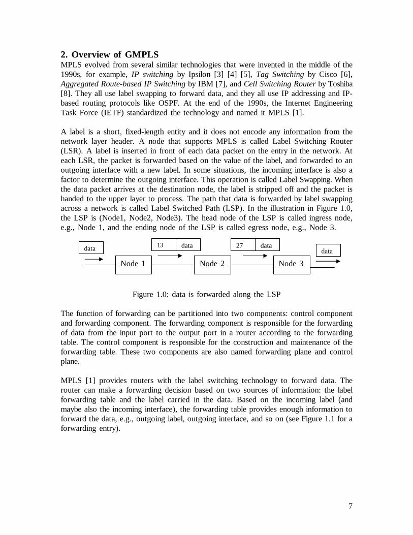
A label is a short, fixed-length entity and it does not encode any information from thenetwork layer header. A node that supports MPLS is called Label Switching Router(LSR). A label is inserted in front of each data packet on the entry in the network. Ateach LSR, the packet is forwarded based on the value of the label, and forwarded to anoutgoing interface with a new label. In some situations, the incoming interface is also afactor to determine the outgoing interface. This operation is called Label Swapping. Whenthe data packet arrives at the destination node, the label is stripped off and the packet ishanded to the upper layer to process. The path that data is forwarded by label swappingacross a network is called Label Switched Path (LSP). In the illustration in Figure 1.0,the LSP is (Node1, Node2, Node3). The head node of the LSP is called ingress node,e.g., Node 1, and the ending node of the LSP is called egress node, e.g., Node 3.
Figure 1.0: data is forwarded along the LSP
The function of forwarding can be partitioned into two components: control componentand forwarding component. The forwarding component is responsible for the forwardingof data from the input port to the output port in a router according to the forwardingtable. The control component is responsible for the construction and maintenance of theforwarding table. These two components are also named forwarding plane and controlplane.
MPLS [1] provides routers with the label switching technology to forward data. Therouter can make a forwarding decision based on two sources of information: the labelforwarding table and the label carried in the data. Based on the incoming label (andmaybe also the incoming interface), the forwarding table provides enough information toforward the data, e.g., outgoing label, outgoing interface, and so on (see Figure 1.1 for aforwarding entry).
Node 1 Node 2 Node 3
data 13 data data27data

8
Figure 1.1 the logical view of an entry in the forwarding table.
MPLS supports data forwarding based on a label. The original MPLS architecture [1]assumes that a Label Switching Router (LSR) has a forwarding plane which can (a)recognize packet (or cell) boundaries, and (b) process packet (or cell) headers. However,there are routers that cannot recognize packet boundaries or process packet headers, e.g.,TDM switches, optical cross-connects (OXCs), etc. But different label modelingtechniques can allow these routers (switches) to forward data using the same principle oflabel switching. For example, the time slot of TDM, the lambda (or wavelength) of aWDM switch, the port of an OXC, etc, can be modeled as a label. That means theforwarding plane is different, but the control plane can be same. Such a technology iscalled Generalized MPLS (GMPLS) [2]. GMPLS extends MPLS. With GMPLS, a switchwhose forwarding plane recognizes neither packet nor cell boundaries can also forwarddata using this extended label switching technology. GMPLS supports multiple types ofswitching: packet (cell), TDM, lambda, and space (port) switching. This means thatGMPLS can forward data based on time slots, wavelengths, physical ports and labels.
GMPLS models wavelength, TDM channels or time slots as labels [9], and the namegeneralized labelrefers to all these different “labels” [10].
2.1 LSP HierarchySo far, GMPLS supports five types of interfaces (see [2]).
(1) Packet Switch Capable (PSC) interfacesThey are interfaces that can recognize packet boundaries and can forward data based onthe content of the packet header. An example is an Ethernet interface of an IP router,which can recognize the header boundary of an IP packet.
(2) Layer-2 Switch Capable (L2SC) interfacesThey are interfaces that recognize frame/cell boundaries and can forward data based onthe content of the frame/cell header. An example is an interface of an ATM switch thatforwards cells based on the label encoded by ATM VCI/VPI.
Incoming information Outgoing information
Incoming label Outgoing label
Outgoing interface
…
…

9
(3) Time-Division Multiplex Capable (TDM) interfacesThey are interfaces that forward data based on the data's time slot in a repeating cycle.An example is an interface of a SONET switch.
(4) Lambda Switch Capable (LSC) interfacesThey are interfaces that forward data based on the wavelength on which the data isreceived. An example includes the interface of an Optical Cross-Connect (OXC), whichcan distinguish lambdas.
(5) Fiber-Switch Capable (FSC) interfacesThey are interfaces that forward data based on a position of the data in the real worldphysical spaces. An example is an interface of a Photonic Cross-Connect (PXC), whichcan operate on a per-fiber basis.
We can see that interfaces (3), (4) and (5) are unable to check the content of the userdata, while (1) and (2) can process the packet (cell) headers.
A circuit can be established only between, or through, interfaces of the same type.Depending on the particular technology being used for each interface, different circuitnames can be used, e.g. SONET/SDH circuit, light-path, etc. In the context of GMPLS,all these are referred to a common name: Label Switched Path (LSP).
In MPLS, LSPs can be nested, e.g., several LSPs of the same level can be multiplexedinto a single LSP of another level. The nested LSP concept in MPLS has been extendedto GMPLS [11]. A new LSP is multiplexed inside an existing higher-order LSP so thatthe preexisting LSP serves as a link along the path of the new LSP [12]. This is referredto as LSP hierarchy. The ordering of LSPs is based on the link multiplexing capabilitiesof the nodes. A hierarchical LSP can be established using the same type of interface, orbetween different types of interface.
A hierarchical LSP can be established if an interface is capable of multiplexing severalLSPs from the same technology (layer). For example, 4 OC-48 links can be multiplexedinto an OC-192 link. A lower order SDH/SONET LSP (OC-48) can be nested in a higherorder SDH/SONET LSP (OC-192) (see Figure 1.2).
10
Figure 1.2: a hierarchical LSP is established on the same type of interfaces.
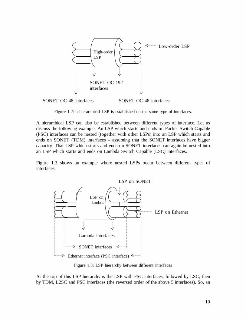
A hierarchical LSP can also be established between different types of interface. Let usdiscuss the following example. An LSP which starts and ends on Packet Switch Capable(PSC) interfaces can be nested (together with other LSPs) into an LSP which starts andends on SONET (TDM) interfaces – assuming that the SONET interfaces have biggercapacity. That LSP which starts and ends on SONET interfaces can again be nested intoan LSP which starts and ends on Lambda Switch Capable (LSC) interfaces.
Figure 1.3 shows an example where nested LSPs occur between different types ofinterfaces.
Figure 1.3: LSP hierarchy between different interfaces
At the top of this LSP hierarchy is the LSP with FSC interfaces, followed by LSC, thenby TDM, L2SC and PSC interfaces (the reversed order of the above 5 interfaces). So, an
High-orderLSP
SONET OC-192interfaces
SONET OC-48 interfaces SONET OC-48 interfaces
Low-order LSP
LSP onlambda
SONET interfaces
Ethernet interface (PSC interface)
Lambda interfaces
LSP on SONET
LSP on Ethernet

11
LSP which starts and ends on PSC interfaces can be nested into an LSP which starts andends on L2SC interfaces. This LSP, further, can be nested into an LSP that starts andends on TDM interfaces, which further can be nested into an LSP that starts and ends onLSC interfaces. Again, the LSP starts and ends on LSC interfaces can further be nestedinto an LSP that starts and ends on FSC interfaces. The example in Figure 1.3 shows athree-level hierarchical LSP. For each level of a given hierarchy, there is a separatecontrol instance. The LSP is independently computed based on that level of routinginformation, and independently signaled. Examples follow in the subsequent sections.
2.2 The Mesh NetworkThe trend of the Internet transport infrastructure is to have an optical network coreinterconnecting high-speed routers (and switches) (see [13]).
A lightpath is a point-to-point optical layer connection between two access points in anoptical network (see [14] for the definition). An example is shown in Figure 1.4. Awavelength connects two edge OXCs through two ports of the OXCs. Note that the twoedge OXCs may be bridged by a number of OXCs and the wavelength may be switchedby these transit OXCs. The lightpath is referred to as an LSP in the context of GMPLS ifthe lightpath is set up by GMPLS signaling.
Figure 1.4: a lightpath
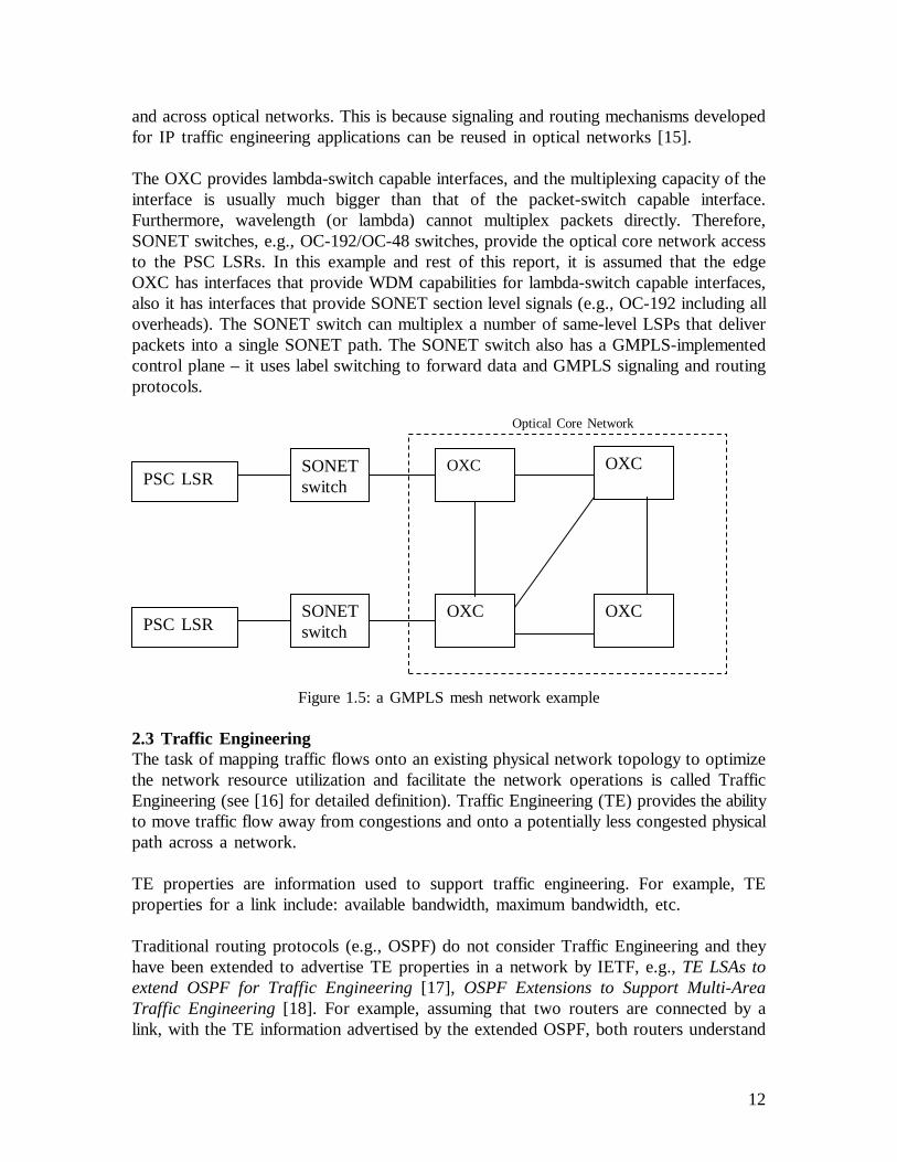
This report only considers the LSP recovery mechanism in a mesh network. An exampleof a mesh network is shown in Figure 1.5. In the example, LSRs which are packet-switchcapable (called PSC LSRs) are connected to SONET switches. And the SONET switchesare connected to an optical core network. One PSC LSR is connected to its peer overdynamically established LSPs across the optical core. The optical core is assumed to beincapable of processing packet headers. It is also assumed that a path must be establishedacross the optical core network before the PSC LSRs can communicate.
The optical core network consists of OXCs that are connected by point-to-point opticallinks. The OXC can operate at the level of individual wavelength. The OXCs are mesh-connected (to form a general topology). Each node has the GMPLS-implemented controlplane. What does it mean? (a) The nodes can forward data using label switching. Forexample, OXCs can forward data by label switching - based on the input wavelength,which is modeled as a label, to make a forwarding decision. (b) Each node uses GMPLSsignaling (e.g., RSVP-TE with extensions) and GMPLS routing protocols (e.g. OSPF-TEwith extensions).
It is recommended that the optical network control plane should utilize IP-based protocols(e.g., signaling and routing) for dynamic provisioning and restoration of light-paths within
Edge OXC Edge OXCOXC cloud
12
and across optical networks. This is because signaling and routing mechanisms developedfor IP traffic engineering applications can be reused in optical networks [15].
The OXC provides lambda-switch capable interfaces, and the multiplexing capacity of theinterface is usually much bigger than that of the packet-switch capable interface.Furthermore, wavelength (or lambda) cannot multiplex packets directly. Therefore,SONET switches, e.g., OC-192/OC-48 switches, provide the optical core network accessto the PSC LSRs. In this example and rest of this report, it is assumed that the edgeOXC has interfaces that provide WDM capabilities for lambda-switch capable interfaces,also it has interfaces that provide SONET section level signals (e.g., OC-192 including alloverheads). The SONET switch can multiplex a number of same-level LSPs that deliverpackets into a single SONET path. The SONET switch also has a GMPLS-implementedcontrol plane – it uses label switching to forward data and GMPLS signaling and routingprotocols.
Figure 1.5: a GMPLS mesh network example
2.3 Traffic EngineeringThe task of mapping traffic flows onto an existing physical network topology to optimizethe network resource utilization and facilitate the network operations is called TrafficEngineering (see [16] for detailed definition). Traffic Engineering (TE) provides the abilityto move traffic flow away from congestions and onto a potentially less congested physicalpath across a network.
TE properties are information used to support traffic engineering. For example, TEproperties for a link include: available bandwidth, maximum bandwidth, etc.
Traditional routing protocols (e.g., OSPF) do not consider Traffic Engineering and theyhave been extended to advertise TE properties in a network by IETF, e.g.,TE LSAs toextend OSPF for Traffic Engineering[17], OSPF Extensions to Support Multi-AreaTraffic Engineering[18]. For example, assuming that two routers are connected by alink, with the TE information advertised by the extended OSPF, both routers understand
OXC OXC
OXC OXC
Optical Core Network
PSC LSR
PSC LSR
SONETswitch
SONETswitch

13
the available bandwidth of the link, the maximum bandwidth of the link, etc. Each routerstores the TE properties in a database, which are learnt from the advertisement providedby the routing protocol. With the TE properties in the database, a node understands theTE properties of the network. And the database of the routers will be synchronized withinthe entire routing area. The information in the database can be used for a pathcomputation algorithm to compute a path across the network to meet the TrafficEngineering requirements.
The Traffic Engineering (TE) link concept is introduced with the current development oftraffic engineering and optical networks. A TE link is a logical link that has TE properties[19]. The Internet draft [19] explains the meaning of “logical”: it is a way to group/mapthe information about certain physical resources (and their properties) into the informationthat is used by CSPF for the purpose of path computation, and by GMPLS signaling.Both ends of the link must do the mapping/grouping consistently. By “consistent”, itmeans the information advertised by one end of the link does not conflict with thatadvertised by the other end of the link. Examples of a TE link are: a physical link, anLSP, or a bundle of physical links. The TE properties of a TE link are exchanged liketraditional link information by routing protocols, e.g., carried by OSPF advertisementmessages.
As we said, an LSP can be regarded as a TE link. Because of the benefits introduced byoptical networks, e.g., high bandwidth, the capacity of an LSP constructed by lambdaslikely cannot be utilized completely by one user. The routing protocol can advertise thisLSP as a TE link into the routing domain, which can be used for the path computationalgorithm to calculate paths, path aggregation (e.g., shared by other LSPs that require aportion of the LSP capacity), etc. We say that there is a “forwarding adjacency” (FA)between the end-nodes of the advertised LSP [20]. And such an LSP is named FA-LSP[20]. As a TE link, the TE properties are also associated with the FA-LSP.
In a hierarchical LSP, the high-order LSPs tunnel low-order LSPs. The high-order LSPshould be advertised by the routing protocol as a TE link (and they become a FA-LSP),so that the unreserved bandwidth is utilized.
We will see examples of the TE link and FA-LSP in the subsequent sections.
2.4 The GMPLS Control PlaneThere are five major functions in the control plane of GMPLS: resource discovery,routing, path computation, link management and signaling. We briefly introduce thesefunctions here and we will specify the portions of these functions that are related to thisreport in the subsequent sections.
Resource discovery is the procedure through which nodes within a network find out theresource in the network. It provides the information for signaling and path computation.Path computation uses an algorithm to calculate an explicit-routed LSP (ER-LSP).

14
The routing function uses the IP-based routing protocols to distribute and maintain theinformation about the topology and resources of the network. The routing protocol is themeans by which non-local resources are discovered. The topology and resources of thenetwork will be taken into account as parameters for the path algorithm to calculate anER-LSP.
Signaling is the procedure through which service provisioning is done. The serviceprovisioning includes LSP establishment, LSP deletion and LSP modification.
Link management is used to manage TE links, e.g., maintain control channel connectivity,localize link failure, and so on.
Control information, e.g., signaling messages, routing messages, link managementmessages, is exchanged through the control channel. The control channel should beseparated from the data channel as IETF recommended [10]. One of the good reasons forseparation is that the control channel should not share the fate with the data channel. Andit does not have to be the same physical medium as the data channel. For example, anOXC uses lambda to transport data, but uses an Ethernet link to transport control signals.
2.4.1 Resource DiscoveryLocal resource discovery is the procedure that a router takes to find out what resource ithas for service provisioning.
When a node starts up, it goes through the neighbor and link discovery procedure, forexample, by manual configuration or an automatic procedure. By combining the results,each node has a database about the local resource, for example, link capacity, wavelength,etc.
After the local resource discovery, each node uses the routing protocol to distribute itslocal resource. When a node receives other nodes’ resources, it stores them in a database.Then, any changes to the resource will also be advertised by the routing protocol. Thuseach node knows about the resource of the entire network.
2.4.2 Enhancements in the Routing Protocol to Support GMPLSConventional routing protocols are reused and enhanced with extensions to supportGMPLS, e.g., OSPF with extensions [21], IS-IS with extensions [22]. They are used todiscover network topology, distribute Traffic Engineering properties and GMPLS-specificfeatures.
Here we introduce the extensions of conventional routing protocols to supportunnumbered links, different interfaces, link protection type and Shared Risk Link Groupdistribution in GMPLS.
15
Extensions to support unnumbered linksOne of the fundamental issues in routing is addressing. Because of WDM, an optical fibermay have a number of channels. The IETF draft [14] suggests an addressing scheme: anIP address is used to identify a node (e.g., a router ID), and a “selector” is used toidentify further fine-grain information within each node.
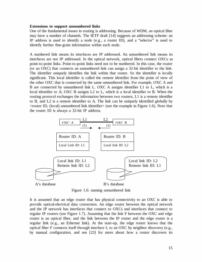
A numbered link means its interfaces are IP addressed. An unnumbered link means itsinterfaces are not IP addressed. In the optical network, optical fibers connect OXCs aspoint-to-point links. Point-to-point links need not to be numbered. In this case, the router(or an OXC) that connects an unnumbered link can assign a 32-bit identifier to the link.The identifier uniquely identifies the link within that router. So the identifier is locallysignificant. This local identifier is called the remote identifier from the point of view ofthe other OXC that is connected by the same unnumbered link. For example, OXC A andB are connected by unnumbered link L. OXC A assigns identifier L1 to L, which is alocal identifier to A; OXC B assigns L2 to L, which is a local identifier to B. When therouting protocol exchanges the information between two routers, L1 is a remote identifierto B, and L2 is a remote identifier to A. The link can be uniquely identified globally by<router ID, (local) unnumbered link identifier> (see the example in Figure 1.6). Note thatthe router ID is always a 32-bit IP address.
Figure 1.6: naming unnumbered link
It is assumed that an edge router that has physical connectivity to an OXC is able toprovide optical-electrical data conversion. An edge router between the optical networkand the IP network has interfaces that connect to OXCs and interfaces that connect toregular IP routers (see Figure 1.7). Assuming that the link F between the OXC and edgerouter is an optical fiber, and the link between the IP router and the edge router is aregular link (e.g., an Ethernet link). At the start-up, the edge router knows that theoptical fiber F connects itself through interface I1 to an OXC by neighbor discovery (e.g.,by manual configuration, and see [23] for more about how a router discovers its
OXC A OXC B
Router ID: A
Local Link ID: L1
Router ID: B
Local link ID: L2
(1) (1)
A’s database
Local link ID: L1Remote link ID: L2
B’s database
Local link ID: L2Remote link ID: L1
L1 L2

16
neighbors). And it knows that an Ethernet link connects itself through interface I2 to anIP router by neighbor discovery. When the edge router creates its routing adjacencyrelationship with its neighbors, it understands what parameters, options and protocolextensions it is going to use. Thus the routing protocol will send out advertisementmessages carrying unnumbered link identifiers to identify link F, and it will send outadvertisement messages carrying IP addresses to identify link L.
Figure 1.7: edge router knows about the links
Extensions to support link protection typeIf a link has a protection capability provided by the link layer, then such a link capabilityshould be considered by the path computation component when calculating/selecting thepath. The link protection type (e.g., 1+1 protection) is one of the traffic engineeringproperties of a link and it is distributed by the routing protocol. The link protection typedoes not have the same meaning when it is carried by signaling protocols as when it iscarried by routing protocols, because it is from a different point of view. When therouting protocol distributes the link protection type for a given link, it means the link hasthe protection capability indicated by the link protection type. Let see what these linkprotection types are.
Extra TrafficA link with type Extra Traffic means it is protecting another link or other links.
For instance, Link 1 and Link 2 connect Node A and Node B. Traffic is goingthrough L2. If Link 1 is of type “Extra Traffic”, it is protecting L2, but there isno traffic going through L1 yet, or the traffic going through L1 is different fromthat going through L2.
In Internet draftRouting Extensions in Support of Generalized MPLS[19], thesentence “The LSPs on a link of this type will be lost if any of the links it isprotecting fail” means a link of this type will be activated when a link it isprotecting fails. So any LSP that is on such a link will be preempted.
UnprotectedNo link is protecting the link that is of type unprotected. If it fails, then the LSPis lost and so is the traffic.
Edge router OXCIP routerFL
I1I2
Node A Node BL1
L2

17
SharedIf the link is of type Shared, it means that there are one or more disjoint links oftype Extra Traffic that are protecting this link.
For instance, Link 1 is protecting one or more links, which is of type ExtraTraffic. Other links that are protected by L1 are of type Shared – they share theprotection relationship.
Dedicated 1:1If the link is of type Dedicated 1:1, it means that there is one dedicated disjointlink of type Extra Traffic that is protecting this link. For instance, in example ofType Extra Traffic (see above), Link 2 is typedDedicated 1:1.
Dedicated 1+1If the link is of type Dedicated 1+1, it means that a dedicated disjoint link isprotecting this link. However, the protecting link is not advertised in the link statedatabase. So if the switchover occurs for a failure, the LSP is still there.
For instance, traffic is sent between two links: L1 and L2. The receiver takes thehealthy one to accept user traffic. Link 2 and Link 1 both are of typeDedicated1+1.
EnhancedA link of type Enhanced means it has a protection capability that is more reliablethan Dedicated 1+1.
If the link information distributed by the routing protocol does not have the linkprotection type, it means it is unknown.
Extensions to support Shared Risk Link GroupWith the development of optical network, e.g., WDM, a number of links can have thesame fate. Because they share the same physical resource, and if the resource is notavailable, then all these links are broken. For example, an optical fiber can contain a
Node A Node B
L1
NodeA
Node BL1
L2

18
number of links. Such a set of links constitutes a Shared Risk Link Group (SRLG) [19].Based on different physical resource, a link may belong to multiple SRLGs.
For path protection/restoration, the links of the backup path must belong to differentSRLG(s) from the ones of the working path. Therefore, the SRLG information is usefulfor the path computation component to compute the path.
Extensions to support different interfacesA link is connected to a node by an interface. GMPLS supports different types ofinterface, e.g., interface which is capable of packet switching, interface which is capable oflambda switching, etc. Different types of interface have different switching capabilities, andeven same type of interface have different switching capabilities. The switching capabilityof the interface introduces a new constraint for path computation and signaling. InGMPLS LSP set up, a LSP must start and end at the same type of interface. So thisinformation needs to be distributed onto the network.
The Interface Switching Capability Descriptor [24] describes the switching capability of aninterface. The IETF draftRouting Extensions in Support of Generalized MPLS[19]defines the following interface switching types:
Packet-Switch Capable-1 (PSC-1)Packet-Switch Capable-2 (PSC-2)Packet-Switch Capable-3 (PSC-3)Packet-Switch Capable-4 (PSC-4)Layer-2 Switch Capable (L2SC)Time-Division-Multiplex Capable (TDM)Lambda-Switch Capable (LSC)Fiber-Switch Capable (FSC)
If an interface is of type PSC, it means that the node receiving data over thisinterface can switch the received data on a packet-by-packet basis. An example isthe Ethernet interface. Types PSC-1 through PSC-4 stand for different levels ofcapability. It means potentially an LSP starts and ends on PSC interface can alsobe nested into another LSP that also starts and ends on PSC interface assumingthat the LSP interfaces have different switching capabilities. However the PSCtypes 1-4 has not been detailed in the draft yet.
If an interface is of type L2SC, it means that the node receiving data over thisinterface can switch the received frames based on the layer 2 address. An exampleis the ATM interface – based on ATM VCI/VPI to switch data.
If an interface is of type TDM, it means that the node receiving data over thisinterface can switch the received data based on the time slot. An example is theSONET interface.

19
If an interface is of type LSC, it means that the node receiving data over thisinterface can recognize and switch individual lambdas within the interface. Anexample is the interface of an OXC (or PXC) that can operate on an individuallambda.
If an interface is of type FSC, it means that the node receiving data over thisinterface can switch the entire contents to another interface. An example is theinterface of an OXC (or PXC) that can operate on an individual fiber.
Besides the switching type, the Interface Switching Capability Descriptor also contains themaximum bandwidth for each priority (range from 0 to 7) that may be reserved on thislink.
A link can be used to transport different data encoded in a different way, e.g., SONET,Lambda, Packet, etc. The data encoding method specifies this information in the InterfaceSwitching Capability Descriptor.
So the Interface Switching Capability Descriptor contains three necessary pieces ofinformation: (1) interface switching type, (2) max (reservable) bandwidth and (3) dataencoding type. Optional information may be attached in the descriptor for some specificinterface types, for example, if the interface is PSC, the Maximum Transport Unit shouldbe specified.An example of an Interface Switching Capability Descriptor is like:
Interface Switching Capability = PSC-1Encoding = Ethernet 802.3Max Bandwidth[0] = 1.0 Gbps, for priority 0
When a node advertises its link information carrying the descriptor, the descriptor onlydescribes the interface that connects the node originating the message. In the example inFigure 1.8, interface I and interface K connect the router A to other nodes. The InterfaceSwitching Capability Descriptor (ISCD) originated by A only describes interface I and K,not the interface of another end of the link.
Figure 1.8: a router advertises the interface descriptor
Router AI
ISCD: interface I descriptor
K
ISCD: interface K descriptor
Router BRouter CJL

20
Traffic Engineering propertiesBesides the above information, there are other TE properties that are distributed byrouting protocols, e.g., maximum bandwidth, available bandwidth, etc. Because these TEproperties are not specific for GMPLS, they will be introduced in the subsequent sections.
We are going to see how these extensions are implemented in OSPF as an example in thesubsequent sections.
2.4.3 Enhancements in MPLS Signaling to Support GMPLSSignaling refers to exchange of information between involved components in the networkrequired to provide and maintain service. GMPLS signaling provides LSP control (e.g.,LSP set-up/release, LSP modification), and it may be used to reserve resources at thesame time when LSP is being established. GMPLS signaling uses enhanced protocols CR-LDP [25] or RSVP-TE [26].
Generalized Label Request and Generalized LabelIn the context of GMPLS, an LSP can be a mix of different types of link. For example,an LSP may have links that connects ATM switches, SONET switches, OXCs and others.And the label should take a different form. These forms of “label” are referred to as ageneralized label.
In the GMPLS signaling, a node explicitly requests a label from its downstream peerwhen it needs one. The signaling message carries a label request, which should tell thedownstream node enough information about the application environment of the desiredlabel. The downstream node responds with a generalized label. It should contain enoughinformation to allow nodes of the LSP to program their label forwarding tables.
Therefore, the signaling message should be extended to support the widening scope ofGMPLS signaling. The label request message should include the following information:
(1) LSP encoding type;(2) Switching type;(3) Generalized Payload ID (G-PID).
An LSP can be used to transport different data encoded in a different way, e.g., SONET,Lambda, Packet, etc. The LSP encoding types are defined in [27].
An interface connects a link to a node. The interfaces supported by GMPLS may havedifferent switching capabilities, for example, packet-switch capable, lambda-switch capable,TDM capable, etc. These are named switching types in GMPLS signaling. A list of theswitching types is defined in [24].
The Generalized Payload ID is an identifier of the payload carried by an LSP. Examplesinclude lambda (using fiber), Ethernet (using fiber or lambda), etc. G-PID is defined in[27].
21
A generalized label has a variable length, which can model different types of “label”, e.g.,wavelength, port, etc, in the context of GMPLS.
Bi-directional LSP setupThere are a number of reasons [28] for using one signaling session to build a bi-directional LSP, instead of building two unidirectional LSP to do the same job. Theadvantages are obvious, e.g., the signaling overhead is less. From the restoration point ofview, the delay to establish a bi-directional LSP to restore the service for a failed bi-directional LSP is less than the restoration delay for a unidirectional LSP. So the GMPLSsignaling should be able to support bi-directional LSP set-up.
Label SetThere are cases in GMPLS that result in label allocation trouble. For example, OXC Aand OXC B are signaling neighbors for the set-up of a new LSP. OXC B (a downstreamnode) assigns label 10 to OXC A (an upstream node), which works as the outgoing labelin A for forwarding data to B. But that label is not available in A (e.g., it does not havewavelength 10 at the interface to B). So the label set is defined in GMPLS signaling,which restricts the label range. For example, assuming that OXC A and OXC B bothsupport GMPLS-RSVP-TE signaling, OXC A puts all the labels that are acceptable to Aitself into the label set. The Path message carries the label set from A to B (fromupstream to downstream). B can pick one of the labels in the set. However, if none ofthe labels in the label set is acceptable to B, B will generate an error and the path set-upwill not continue.
Signaling Link Protection for LSP establishmentDuring LSP signaling in GMPLS, label distribution protocols (RSVP-TE, or CR-LDP)may carry the link protection type. If the link protection type is carried, it means the LSPto be established requires link layer protection. The link protection type indicates whatlink protection capability is desired for the links constructing the LSP to be set up. Thelink protection type is one of the TE requirements (or a constraint) for an LSP, so thesignaling for the LSP will not continue if the desired link protection cannot be provided.There are six link protection types defined by [27]. They have been specified in theprevious section of this report. For example, the signaling protocol carries link protectiontype Dedicated 1+1, and it means the LSP to be established requires the link that hasDedicated 1+1protection.
Indication of the LSP roleThere are two LSP roles: primary or secondary (backup). The GMPLS signaling protocolcarries a flag that indicates if the LSP being set up is primary or secondary. Theresources allocated for a backup LSP are not used until the primary LSP fails. Becausethe resource allocation has priorities (carried by the signaling protocol), the resourceallocated for a backup LSP may be used by an LSP that has lower priority until theprimary LSP fails and the traffic is switched over to the backup. At that time, all theLSPs using the resource allocated for the backup LSP must be preempted.

22
2.4.4 Path ComputationTraditional IP routing algorithms aim to find a path that optimizes a certain scalar metric(e.g. minimizes the number of hops), and such a method causes a number of networkproblems, e.g., network congestions, violation of network administration, etc.
Constraint-based routing algorithms set out to find a path that optimizes a certain scalarmetric and at the same time does not violate a set of constraints. Such a path is calledconstraint-based path. It is the ability to find a path that does not violate a set ofconstraints that distinguishes constraint-based routing from conventional IP routing.
The constraints include QoS requirements, administrative policies, etc. Because we arestudying the LSP protection/restoration mechanism, the constraint of interest is that thebackup path must not share a link/node with the primary path except the initiator nodeand the terminator node. In particular, the information of Shared Risk Link Group andLink Protection Type are of interest to us. Note that the LSP role is for resourceallocation and usage.
We need to compute a path to implement constraint-based routing. The path computationcomponent in GMPLS control plane is used to do such a job. Path computation is usedto select an appropriate route between two clients through the optical network for explicitrouting.
In each node of the network, there is a database TE-LSDB that stores the information ofall the links in the network, e.g., TE properties. This is the prerequisite for pathcomputation. After all, we must know about the network before we calculate anything.Also, it means that the constraints we considered in the path computation are within thescope defined by the information in the TE-LSDB.
For a hop-by-hop routed LSP, there is no need to have path computation. When thesignaling is done, it carries the desired Link Protection Type. Every node receiving thesignaling message must honor the desired link protection for the LSP being established;otherwise, the signaling will not go through (see the subsequent section for more). Notethat a hop-by-hop routed LSP cannot be the backup LSP, because there is no guaranteethat the links/nodes traveled by such an LSP are not part of the primary LSP. The transitnode is not supposed to keep track of the information about primary/backup LSP pairs,because there could be thousands of LSPs that go through a node.
Path computation is used to provide end-to-end LSP protection using the explicit-routedLSP (ER-LSP). If the primary LSP is an ER-LSP, then the backup LSP can be calculatedfollowing the primary LSP computation. If the primary LSP is a hop-by-hop routed LSP,and we know the nodes traveled by a hop-by-hop routed LSP, then we can also computea path and use ER-LSP to create its backup. Otherwise, end-to-end LSP protection is notapplicable.

23
Usually, constraint-based routing requires path computation at the LSP initiator node. Thisis because different LSP initiator node may have different constraints for a path to thesame destination, and the constraints associated with a particular LSP initiator node areonly known to that node. The reason is similar to source routing – the source determinesthe path.
The Shortest Path First (SPF) algorithm computes a path that is optimal with respect tosome scalar metric. Many people (see [29]) propose that it is possible to modify the SPFalgorithm in such a way that it can take into account the constraints. The algorithm isreferred to as Constraint-based Shortest Path First (CSPF). There have been a number ofproposals for CSPF, like [29]. The study of CSPF is out of the scope of this report, buta simple algorithm for CSPF is introduced to illustrate what CSPF is. It consists of threemajor steps:
(1) Among all the links, exclude the ones that violate the constraints we defined.(2) According to the administration policy, map one (or more) link TE property as thescalar metric (cost) of the link.(3) Use the SPF algorithm to calculate the path.
Based on (1), we know that all the links we consider will not violate the constraints, andso will be the path. For example, the link color stands for an administrative constraint. Ifwe want a path that is only within the “red” domain, then only the links with color “red”are considered. The user’s requirement is also a constraint – in fact, it is the mostimportant one from the service point of view. If a user wants a path in which each linkmust have bandwidth 5Mb/s, then we do not consider all the links whose availablebandwidth (the difference between the maximum bandwidth that may be reserved on thislink and the bandwidth that has bee allocated) is less than that.
With regard to path computation for LSP protection/restoration, the constraint is that thelinks traveled by the backup LSP must not belong to the same Shared Risk Link Group(SRLG) as the primary LSP. Therefore, after the computation for the primary LSP, alllinks belonging to the SRLG to which the links of the primary LSP belong are excluded(not considered).
In order to avoid the protection contention between LSP layer and link layer (see Section5.1.2), [30] proposes that the Link Protection Type of the links traveled by the LSPs thatconstruct the protection mechanism should be “unprotected”. Such a proposal is thesecond constraint that should be the considered if we follow that proposal.
With regard to (2), we can take any of the TE properties or administrative distance.
Let us have an example. We will establish an LSP that requires T1 bandwidth (1.544Mb/s), which travels from Node 1 to Node 5. In Figure 1.9, the link directly from Node1 to Node 5 has only 1 Mb/s available; others have enough or more. So the link fromNode 1 to Node 5 is excluded. Then we consider the available bandwidth as the metric.

24
The cost of a link is calculated by (108 / available bandwidth). The link from Node 1 toNode 2 has available bandwidth 10 Mb/s, so the cost is 10. In such a way, the metric ofevery link is calculated (see Figure 1.10). Then, using the SPF algorithm, the shortestpath from Node 1 to Node 5 is (Node1, Node4, Node3, Node5).
Figure 1.9: available bandwidth in the network
Figure 1.10: the metric of the links to be used by SPF algorithm
In general, path computation can be control-driven or data-driven. If the path computationis triggered by administrative control, e.g., the network administer configures a path andrequires the path computation for an ER-LSP, then the path computation is calledcontrol-driven. The data-driven path computation does not require administration. Userdata arrives at a node. In order to deliver the data, the node computes a path beforesignaling the LSP. Path computation is triggered by the data’s arrival, and it is calleddata-driven. Using the control-driven mode, the path can be pre-calculated and even pre-established (before user data arrives), so it is faster in response to data delivery.
Node 1 Node 2
Node 3
Node 4
Node 5
10
50
10
30
2060
Node 1 Node 2
Node 3
Node 4
Node 5
10Mb/s
2Mb/s
10Mb/s
1Mb/s
1.667Mb/s5Mb/s
3.333Mb/s

25
3. Overview of Path Protection/RestorationWith the development of networks, new technologies provide high bandwidth capacity.The ever-increasing bandwidth leads to a significant data loss if a failure cannot berecovered timely. Users and network service providers require network survivability. Forexample, real-time applications require very fast network recovery. No network serviceprovider wants unprotected networks. On the other hand, transmission systemsdeployment gives chances to network failure, for example, telecommunication fiber cablesshare the same ducts of other utility transport media. Cable cuts are difficult to avoid.
Network survivability has been a hot research topic in the industry. Today, multiple layerprotection/restoration is possible. The protection/restoration mechanism can beimplemented in the link layer or in the IP/GMPLS layer. For example, the architecture ofan IP-over-WDM node can be viewed logically as:
Figure 2.1: a logical view of the architecture of a GMPLS node
Protection/restoration mechanisms at the IP/GMPLS require relatively more time torecover, and using higher levels of recovery mechanisms may require more resources [31].But there are limitations and disadvantages in the link layer protection, particularly in theoptical network, e.g., complicated implementation, cost, instability due toduplication offunctions, etc. It is still a challenge to implement recovery mechanisms at the WDM layerfor the time being. Today a number of proposals have been studied in the industry tosearch for recovery mechanisms at the WDM layer, such as [32] and [33]. Furthermore,link layer protection cannot easily provide node protection [34]. The study of link layerrecovery mechanisms is out of the scope of this report.
The motivation for using multiple layer protection is to provide the desired level ofservice in the most cost-effective manner [35]. With multiple layer protections, we needto prioritize them. The recovery mechanism that has higher priority is triggered first torecover failures. Usually, it is expected that lower layer recovery mechanism is closer tothe failure, so it has higher priority. Also we need a coordination mechanism to avoidcontention between different layer recovery schemes. One of the most popularcoordination mechanisms is the hold-off timer. The hold-off time is the waiting timebetween the detection of a failure and taking MPLS-based recovery action. It allows timefor lower layer protection to take effect [36]. If MPLS-based recovery is the onlyrecovery mechanism desired, then the hold-off time may be zero. Assuming that we haveSONET Automatic Protection Switch (APS) link protection, for example, within the hold-off time, GMPLS LSP path protection waits for the APS protection to switch. If theSONET APS succeeds protection within the hold-off time, then the hold-off timer is reset
Physical layer (e.g., optical fiber)
Link layer (e.g., WDM)
IP/GMPLS

26
and no further protection is needed. The original LSP can remain there. From this pointof view, the link layer protection provides a means for LSP protection. Section 2.4.3specifies how LSP signaling requires link layer protection when the LSP is beingestablished. If the hold-off time expires, the LSP protection/restoration is triggered. Thecoordination mechanism introduces a tradeoff between rapid recovery and creation of arace condition where several layer protection mechanisms respond to the same fault.
GMPLS widens the application scope of MPLS, and people propose using GMPLS tobuild a unified control plane to manage all kinds of network nodes [14]. The GMPLSLSP protection/restoration has been an important recovery mechanism for networksurvivability.
Differently from traditional IP networks, MPLS networks establish label switched paths(LSPs) before data forwarding occurs. This potentially allows MPLS networks to pre-establish protection (backup) LSPs for working LSPs, and achieve better survivability thantraditional IP networks.
Here we introduce what we need for the LSP protection/restoration mechanism inGMPLS networks.
(1) A method for computing the working and protection paths;(2) A method for working and protection path signaling;(3) A fault detection mechanism;(4) A fault localization and notification mechanism to localize the fault and conveythe information;(5) A recovery mechanism to move the traffic over from the working path to theprotection path or to reroute the fault;(6) A repair detection mechanism to detect the original working path is fixed;(7) An optional switchback or restoration mechanism to restore the traffic to theoriginal working path.
Item (7) is optional and it is not time-sensitive. In some cases, it may not bedesirable. For example, switching the traffic back to the original working path candisrupt the traffic (even for a very short time). It may not be desired under theuser requirements. Item (6) may not be necessary in some cases. For example, if(7) is not wanted, then (6) is no needed.
Item (1) is implemented by the path computation component. For example, it usesCSPF to compute a path and selects the working and protection path. Usually it isproprietary. The path computation considers the Traffic Engineering properties ofthe network, administrative constraints and user requirements to calculate thebackup and working path. For example, if both Link L and K share the samephysical resource (e.g., they exist in the same optical cable), then either L or Kshould be considered in a particular working path computation and its backup.

27
As we introduced in the last sub-section, the GMPLS signaling protocols carriesthe link protection information, which can allow the nodes on the network toidentify the working and backup path.
Traditional methods to monitor the health of data links may not be useful anymore. For example, pure optical switches may not allow these methods to checkthe bit-rate, format or wavelength. Fault detection should work at the layer closestto the failure in order to achieve quick response. In optical network, this shouldbe located in the physical layer (e.g., optical layer). For example, one method offault detection at the optical layer is detecting the loss of light (LOL). Usingsoftware can also detect a faulty link/node, and it will be introduced in thesubsequent section. However, fault detection at the physical layer provides fastand reliable solution, and it is preferred if it is applicable.
The optical network has its own character in failure. When one link is broken,e.g., a fiber cut, all the downstream nodes (in terms of data flow) can detect lossof light. Therefore, we also need a method to localize the failure. The LinkManagement Protocol provides a method, which will be introduced in thesubsequent section.
Both GMPLS signaling protocols [26] and [25] are being extended to providemethods to support LSP protection/restoration. For simplicity, we use the termRSVP-TE to refer to [26] and CR-LDP to [25] from now on.
There are a number of objectives for the LSP protection/restoration mechanism.The LSP protection/restoration mechanism should(1) optimize the use of resources;(2) provide fast recovery and minimize the disruption to data traffic of any failure;(3) minimize degrading the traffic and preserve the constraints on the traffic afterswitchover;(4) minimize the recovery overhead (be simple);(5) be cost-efficient.
At the end of our discussion, we will see that some of the above objectives areconflicting. There is a trade-off between them. It is impossible to achieve all of theseobjectives at the same time, and the choice depends on what the user wants and what isthe network administration goal.
4. Multiple Protocols Contribute to GMPLS LSP Protection/Restoration4.1 OSPF ExtensionsThe current routing protocols OSPF and IS-IS are extended to support TrafficEngineering and GMPLS. Here we take the popular OSPF as an example to see how itworks.

28
The OSPF protocol is re-used to distribute information to support Traffic Engineering andGMPLS features. Two types of extensions have been added to the OSPF: TE extensionsand extensions for GMPLS. The former is named OSPF-TE, which distributes TEproperties over the network. The latter is referred to as GMPLS-OSPF, which distributesextensions dedicated to support GMPLS.
In the OSPF protocol, the message describing the local link information that is floodedthroughout the network is named Link State Advertisement (LSA). A new LSA - TELSA is defined to support Traffic Engineering and GMPLS (see [37] for moreinformation).
The Type-Length-Value (TLV) structure (see Figure 3.1) is used as the payload in the TELSA. The Type specifies the type of the data; the length specifies the length of the wholeTLV structure, and the Value describes the information regarding to Traffic Engineeringand GMPLS support.
Figure 3.1: the TLV structure
The TLV structure can be nested, for example, sub-TLVs are carried as the value in thehigher-level TLV. So it is extendable, which is good for future development. There aretwo TLVs: router address TLV and link TLV.
Router address TLVThe router address is the router ID of the node that advertises the LSA. The TE LSAmust carry a router address TLV. It is type 1, the length is 4, and the value is the 4-octetIP address.
Link TLVThe link TLV contains information about the link. And it consists of a set of sub-TLVs,each of which describes a piece of particular information about Traffic Engineering orGMPLS features. The information of these sub-TLVs are introduced in the subsequentsections. The Link TLV is type 2 and the length varies.
OSPF does not process the contents of the TE LSA.
4.1.1 Introduction to Traffic Engineering Extensions to OSPF (OSPF-TE)When a router starts, it discovers the information about its own links (interfaces) – thelinks connecting the router to networks (or other routers). Then the routing protocol isused to advertise the information to other routers. The information is passed around fromrouter to router. Ultimately, every router has identical information about the network and
Type Length
Value …

29
the information is stored in a database named Link State Database (LSDB). Each routerwill independently calculate the best path to other nodes in the network using a pathcomputation algorithm. For example, the popular OSPF protocol uses Dijkstra’s ShortestPath First (SPF) algorithm to come up with a SPF tree, which serves as a map for datarouting (see Figure 3.2). Then according to routing policies, an appropriate route isselected and put into the routing table.
Figure 3.2: from LSDB to an appropriate route
Conventionally, the information of the links includes the status of the links (e.g.,up/down), metric (cost), etc. The information does not support Traffic Engineering. Forexample, the metric is assigned to routes as a means of ranking them from the mostpreferred to the least preferred. The calculation of the metric is static. The bandwidthmetric used in Cisco routers is calculated as: metric = 108/(link bandwidth). Thus ahigher-bandwidth path is always preferred over a lower-bandwidth path. But what if a T1link of the preferred path is heavily loaded with traffic and a 64k link is lightly loaded?
Because the TE properties (e.g., bandwidth availability, administrative constraints) are notprovided or considered in conventional routing protocols, the routing decision does notsupport Traffic Engineering.
Relying on the current routing protocols, TE properties are added into the messages thatare flooded throughout the network. In IETF, the draft OSPF-TE [37] proposes thefollowing TE properties that should be considered to support Traffic Engineering, andthey rely on the OSPF opaque LSA advertising mechanism to distribute the TEproperties. Each of the following 9 items constructs a sub-TLV in the link TLV of theTE LSA. Note that they are optional except the first two sub-TLVs: Link type and LinkID.
1 - Link type2 - Link ID3 - Local interface IP address4 - Remote interface IP address5 - Traffic engineering metric6 - Maximum bandwidth7 - Maximum reservable bandwidth8 - Unreserved bandwidth9 - Resource class/color
LSA database(LSDB)
SPF algorithmSPF tree
Routingpolicies Routing
table
30
Link typeIt specifies if the link is (1) point-to-point or (2) multi-access link. For the time being,only point-to-point link is completely supported.
Link IDThe Link ID identifies the remote end of the link. For point-to-point links, this is theRouter ID of the neighbor.
Remote Interface IP AddressIt specifies the IP address of the neighbor's interface corresponding to this link. Forunnumbered links, this is the link remote identifier (see Section 2).
Local Interface IP addressIt specifies the IP address(es) of the interface corresponding to this link. If there aremultiple local addresses on the link, they are all listed in the appropriate structure of arouting message. For unnumbered links, this is the link local identifier (see Section 2).
The local and remote interface IP addresses identify the parallel links between two nodes.
Traffic Engineering MetricA metric is a variable assigned to routes as a means of ranking them from best to worstor from most preferred to least preferred. The Traffic Engineering metric specifies the linkmetric for traffic engineering purposes. This metric may be different than the standardOSPF link metric.
Maximum BandwidthIt specifies the maximum bandwidth that can be used on this link from the LSA-originating router to its neighbor. For example, a T1 link has maximum bandwidth 1.544Mb/s, an OC-48 link has around 2.5 Gb/s.
Maximum Reservable BandwidthIt specifies the maximum bandwidth that may be reserved on this link in the directionfrom the LSA-originating router to its neighbor. Note that this may be greater than themaximum bandwidth (the link may be oversubscribed). For example, an OC-48 link maybe configured to have maximum reservable bandwidth 2.75 Gb/s (10% oversubscribed).
Unreserved BandwidthIt is the difference between the Maximum Reservable Bandwidth and the bandwidth thathas been reserved. There are eight priority levels (from 0 to 7) of unreserved bandwidth.This information specifies the unreserved bandwidth of each priority level. Priority 0 is thehighest.
Resource Class/ColorIt specifies administrative group membership for this link, in terms of a bit mask. A linkmay belong to multiple groups - if so it has multiple bit masks.
31
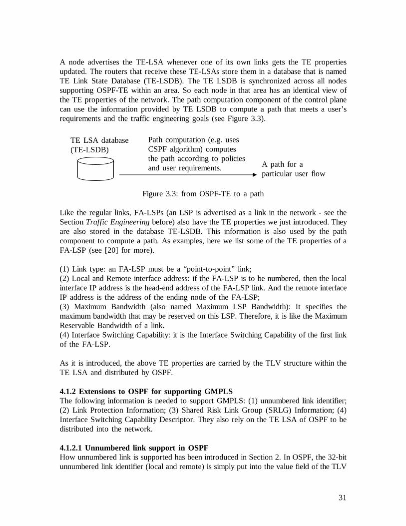
A node advertises the TE-LSA whenever one of its own links gets the TE propertiesupdated. The routers that receive these TE-LSAs store them in a database that is namedTE Link State Database (TE-LSDB). The TE LSDB is synchronized across all nodessupporting OSPF-TE within an area. So each node in that area has an identical view ofthe TE properties of the network. The path computation component of the control planecan use the information provided by TE LSDB to compute a path that meets a user’srequirements and the traffic engineering goals (see Figure 3.3).
Figure 3.3: from OSPF-TE to a path
Like the regular links, FA-LSPs (an LSP is advertised as a link in the network - see theSectionTraffic Engineeringbefore) also have the TE properties we just introduced. Theyare also stored in the database TE-LSDB. This information is also used by the pathcomponent to compute a path. As examples, here we list some of the TE properties of aFA-LSP (see [20] for more).
(1) Link type: an FA-LSP must be a “point-to-point” link;(2) Local and Remote interface address: if the FA-LSP is to be numbered, then the localinterface IP address is the head-end address of the FA-LSP link. And the remote interfaceIP address is the address of the ending node of the FA-LSP;(3) Maximum Bandwidth (also named Maximum LSP Bandwidth): It specifies themaximum bandwidth that may be reserved on this LSP. Therefore, it is like the MaximumReservable Bandwidth of a link.(4) Interface Switching Capability: it is the Interface Switching Capability of the first linkof the FA-LSP.
As it is introduced, the above TE properties are carried by the TLV structure within theTE LSA and distributed by OSPF.
4.1.2 Extensions to OSPF for supporting GMPLSThe following information is needed to support GMPLS: (1) unnumbered link identifier;(2) Link Protection Information; (3) Shared Risk Link Group (SRLG) Information; (4)Interface Switching Capability Descriptor. They also rely on the TE LSA of OSPF to bedistributed into the network.
4.1.2.1 Unnumbered link support in OSPFHow unnumbered link is supported has been introduced in Section 2. In OSPF, the 32-bitunnumbered link identifier (local and remote) is simply put into the value field of the TLV
TE LSA database(TE-LSDB)
Path computation (e.g. usesCSPF algorithm) computesthe path according to policiesand user requirements. A path for a
particular user flow

32
structure. The type is 11. If the remote identifier is unknown (e.g., at the router start-up),then it is 0. Carried by the TE LSA, the unnumbered link identifier is advertised.
4.1.2.2 Shared Risk Link Group (SRLG)The SRLG is also a link property and it is advertised by the link sub-TLV. The SRLG isspecified by a 32-bit word, contained in the Value field of the sub-TLV structure. Thesub-TLV type is 16. If a link can belong to multiple SRLG, then all of them are listed inthe sub-TLV structure and the order is irrelevant. An example is shown in Figure 3.4.
Figure 3.4: SRLG sub-TLV
4.1.2.3 Link Protection TypeThe link protection type can be considered by the path computation component tocompute a path and it is distributed throughout the network. There are six link protectiontypes (See Section 2.4.2 of this report for what they are.):(1) Extra Traffic;(2) Unprotected;(3) Shared;(4) Dedicated 1:1;(5) Dedicated 1+1;(6) Enhanced.
If the routing protocol does not distribute the link protection type for a link, then theprotection attribute of that link is unknown.
The link protection type is encoded in a sub-TLV of the link TLV. The sub-TLV type is14 and it has 4 octets (see Figure 3.5). But only the first octet is used. The first octet isused for indicating protection types and the other octets are reserved. The first octet maycontain the following value to indicate the link protection type:
0x01 Extra Traffic0x02 Unprotected0x04 Shared0x08 Dedicated 1:10x10 Dedicated 1+10x20 Enhanced0x40 Reserved0x80 Reserved
Sub-TLV type: 16 Length: 12 (octets)
SRLG Value: 10
SRLG Value: 11
32 bits

33
Figure 3.5: the Value field of the sub-TLV for link protection type
4.1.2.4 Interface Switching Capability DescriptorThe interface switching capability is encoded by a sub-TLV (type 15) of a link TLV. Thefield contains one of the following codes. And each code signals the correspondent type.
Code Type1 Packet-Switch Capable-1 (PSC-1)2 Packet-Switch Capable-2 (PSC-2)3 Packet-Switch Capable-3 (PSC-3)4 Packet-Switch Capable-4 (PSC-4)51 Layer-2 Switch Capable (L2SC)100 Time-Division-Multiplex Capable (TDM)150 Lambda-Switch Capable (LSC)200 Fiber-Switch Capable (FSC)
The code is not consecutive, as it allows for future extension.
4.2 Link Management Protocol (LMP)Neighboring nodes may run the Link Management Protocol (LMP) [38] for linkmanagement. With the development of optical networks, nodes include photonic switches(PXCs), optical crossconnects (OXCs), routers, switches, add-drop multiplexors, WDMsystems and so on. LMP support any type of nodes. And LMP supports TE links.
The link multiplexing capability has an effect on how to do the link management, e.g.,resource allocation. To allow interworking between links with different multiplexingcapability, sub-channels of a component link should be able to be configured as a datalink. For example, several Ethernet links are multiplexed into an OC-12 link, which isconnected to a node. The node should allow each Ethernet link to be configured as adata link. So that link management on each Ethernet link is possible if required.
To run LMP, a control channel must be established between the node pair. The controlchannel should be separated from the data channel [10]. And, the node pair cancommunicate bi-directionally at least through one of the control channels. If so, then anLMP adjacency can be formed between the two nodes. Multiple active control channelsare possible in an LMP adjacency, and the control channel ID (CCID) is used to identifyeach one.
LMP messages are encoded as data in IP packets, and it runs directly over IP except forthe LMP Test message. The LMP Test message is sent over the data links (in-band) for
Protection type reserved

34
link connectivity verification. So optionally it is limited by the transport media, e.g., notnecessarily encoded as data in IP packets.
LMP functions are: control channel management, link property correlation, linkconnectivity verification, and fault management.
(1) Control channel management is used to establish and maintain control channelsbetween LMP adjacent nodes. The control channel can be used to exchange routing,signaling, and other control messages.
To establish the control channel, the IP address for the far-end of the control channelmust be known (e.g., by configuration). A node sends a LMP Config message to itsneighbor, which contains parameters, e.g., the LMP keep-alive interval. The receiver ofthe Config message must reply an acknowledgement. If both sides agree on theparameters, the control channel is established. After that, the LMP keep-alive message issent periodically to maintain the control channel.
After two neighboring nodes successfully establish the control channel, control messagescan be exchanged through the control channel. Examples of these control messages maybe label distribution information implemented by RSVP-TE, network topology and statedistribution information implemented by OSPF-TE, fault management implemented byLMP, and so on.
(2) Link property correlation is used to synchronize the properties of the TE link andverify the configuration. An example of TE link is shown in following figure. LSP istaken as a TE link by Node1 and Node3, which is constructed by link (A, B) and link (C,D). Link (A, B) or link (C, D) is called a data link.
Figure 3.6: An LSP as a TE link starting from Node1 to Node3
After the LSP is established by the signaling protocol, LMP may be used to synchronizethe properties of the TE link. So, Node1 may send a LMP LinkSummary message toNode3, which is constructed by LMP objects as:
<LinkSummary Message> ::= <LMP message header><Message ID><TE Link><Data Link (A, B)><Data Link (C, D)>
Within each Data Link object, sub-objects may contain information about link reservablebandwidth, wavelength if there is any, interface switching capability such as interface Afor data link (A, B).
Node 1 Node 2 Node 3A B C D

35
The receiver of LinkSummary message must verify that the information obtained from themessage makes sense and matches the information that is stored in the routing databaseor configuration inventory. For instance, the interfaces A and D must be of the sameinterface switching capability type in the example shown in Figure 3.6. The receiver of aLinkSummary message must reply an acknowledgement, which reports the correctness ofthe TE link properties.
(3) Link connectivity verification is used to verify the physical connectivity of the datalinks between the nodes.
In the example shown in Figure 3.6, Node1 and Node3 may exchange LMP Testmessages between interface A and D through link (A, B) and (C, D) to verify thephysical connectivity of the TE link on a periodic basis. The verification messaging mustbe transported by the data-bearing channel, not the control channel.
(4) Fault managementprovides a fault localization procedure. Because the LMP faultmanagement is within the scope of this report, let us discuss it in detail.
The Link Management Protocol introduces a fault localization procedure to localizefailures. It can localize the path failure by quickly reporting the status of one or moredata link. It is designed to work for both unidirectional and bi-directional LSPs.
During the Link Property Correlation, both LMP-capable nodes can signal whether theysupport LMP fault management. If they do, then LMP fault management messagingbecomes one of the control signals between these two nodes.
In optical networks, e.g., nodes are PXCs in the network, if one of the data links fails,then all the downstream nodes (in terms of data flow) may detect the failure due to thenature of light, e.g., loss of light. The LMP fault management requires each node that hasdetected the failure to send a LMP ChannelStatus message to the upstream node. ThisChannelStatus message can report all the broken channel/links together. The upstreamnode must acknowledge the message by a LMP ChannelStatusAck message. Then theupstream node checks if there is any local data link failure, for example, it checks if theinput side has any signal. If the input side is working fine, the failure is localized;otherwise, the node will continue sending LMP ChannelStatus messaging upstream. Afterthe local checking, the upstream node must send a ChannelStatus message to thedownstream node to report the status.
On the other hand, after the downstream node receives the ChannelStatusAck, it expectsa ChannelStatus from the upstream node. If it receives no ChannelStatus, it should send aChannelStatusRequest to solicit the message.
The time-sequence diagram in Figure 3.7 outlines how it works. Let us suppose thatNode 2 is the downstream node relatively to Node 1 (in terms of data flow). Node 2detects a failure.

36
Figure 3.7: channelStatus messaging
When the fault is localized, the upstream node which connects the failed link shouldtrigger the signaling to get protection/restoration. And it does not perform LMPChannelStatus messaging to upstream nodes any more.
Let us have an example to see how it works in a pure optical network. There are threePXCs in the example shown in Figure 3.8. An LSP travels the data links of these threenodes. The control channel is out-of-band. Assuming that the data link through which theLSP with the flow direction from PXC 1 to PXC3 is failed. Both PXC 2 and 3 candetect the failure. For simplicity, only one direction of the LSP is shown.
Figure 3.8: LMP fault management localizes the fault
PXC 3 sends the LMP ChannelStatus message to PXC 2, which acknowledges with aChannelStatusAck. PXC 2 locally finds out that there is no input signal and the failure ispropagated from upstream. So it tells PXC 3 also by a ChannelStatus message.Meanwhile, PXC 2 sends another ChannelStatus message to PXC 1, which tells PXC 1that no signal comes in. PXC 1 replies with a ChannelStatusAck. PXC 1 locally finds outthat the input is fine. So it sends PXC 2 a ChannelStatus message, which tells PXC 2that it is clear. Thus PXC 1 has localized the failure. After that, the recovery will betriggered, for example, signaling starts to establish a reroute. Section 5 will specify therecovery mechanisms in detail.
If the failure affects both directions of the LSP, e.g., a fiber cut, then the same procedureis performed on each direction.
PXC 2PXC 1 Controlchannel
Node 1 Node 2
(1) ChannelStatus
(2) ChannelStatusAck
(3) ChannelStatus
PXC 3Controlchannel
LSP

37
4.3 GMPLS SignalingThere are two major label distribution protocols to perform GMPLS signaling: RSVP-TEwith extensions and LDP with extensions.
4.3.1 GMPLS signaling: RSVP-TE with extensionsTraditional RSVP (RFC2205) provides a means for an application to communicate itsQoS requirements to an Integrated Services Internet infrastructure. RSVP is a controlprotocol that signals QoS requirements on behalf of a data flow. Before data deliveryoccurs, RSVP establishes a resource reservation for a simplex (one way) flow along itspath. A simplex flow is a unidirectional flow traveling from its source to its destination.To allow duplex (two-way) communication, we need RSVP to reserve resource twice –one for each direction. RSVP consults a routing table in a router for the next hop. RSVPrelies on IP or UDP for message transport.
RSVP must carry the following information:• Information for flow identification, so that the flows with particular QoS requirementscan be recognized within the network. This may include sender IP address, receiver IPaddress, port numbers and so on.• Traffic specification and QoS requirements.
RSVP carries the information from the source host to the destination host along therouter/switch on the path. There are two basic messages in RSVP: PATH and RESVmessages. A PATH message travels from the sender to the receiver and include trafficspecification and classification information provided by the sender. The PATH messageidentifies the path from the sender to the receiver and it collects status about the resourcealong the path. When the PATH arrives at the receiver, the receiver sends back a RESVmessage back toward the sender along the reverse of the path. The RESV messagecommunicates with every router to make a resource reservation. See the following figurefor PATH/RESV messaging.
Figure 3.9: RSVP signaling to reserve resource
Each router along the path creates a software record (software state) for the particularflow, which keeps the flow classifier, QoS requirements, next hops, previous hops andother related information. These records have a timer, which means these software stateswill be removed after some time-out. So after some time period, the PATH message is
Sender ReceiverIP router IP router
Resv message
User traffic direction
Path message(1) (2) (3)
(4)(5)(6)

38
transmitted and the RESV travels the reverse path – the process repeats on a regular timeinterval basis. This is called refresh messaging, which keeps the software states and therouter can continue providing QoS to the flow.
Extensions have been added to RSVP (RSVP-TE) to support label distribution for LSPsignaling in MPLS. To establish an LSP, the sender node, with respect to the path,creates an RSVP Path message which contains a LABEL_REQUEST object. TheLABEL_REQUEST object indicates that a label binding for this path is requested. ASESSION_ATTRIBUTE object is introduced to provide additional control informationsuch as setup and hold priorities, local protection and so on. The RSVP-TE Path messagecarries this object during LSP signaling. When the Path message arrives at the destinationnode of a LSP, the node responds to the LABEL_REQUEST object with a LABELobject in its RSVP-TE Resv message. If the node is not the sender node, it allocates afree label and puts it into the LABEL object. And the Resv message is sent to theupstream node. The node that receives a Resv message with a LABEL object will use thislabel as the outgoing label in the forwarding entry of its forwarding table. It also allocatesa free label for the upstream node, and puts it into the LABEL object attached to theResv message. The Resv message is sent upstream again. Such a label distributionprocedure repeats until the Resv message arrives at the sender node. The LSPestablishment is done. The sender node has some criteria to classify different traffics andputs the predefined traffic into the appropriate LSP. In the example shown in Figure 3.10,the sender node will attach label 3 to all the packets before it forwards the packets out.When the packet arrives at the transit IP router, the label is replaced by 6 and thenforwarded again. Such a label swapping procedure repeats on each node and the packetfinally reaches the destination.
For label distribution, the LABEL_REQEUST and LABEL objects are mandatory, butother objects defined in RSVP-TE are optional, e.g., the SESSION_ATTRIBUTEmentioned above.
Note that because the label distribution is done with RSVP, each router can associate theresources with the LSP during LSP signaling. Therefore, resource reservation can be donein the meanwhile.
Figure 3.10: RSVP-TE signaling to distribute labels for establishing LSP
Sendernode
Destinationnode
Transit IProuter
RESV message with labelUser traffic direction
Path message with label request
Label = 6
Incoming label: 3 Outgoing label: 6
The forwarding entry in the transit MPLS router
Label = 3
(1) (2)
(3)(4)
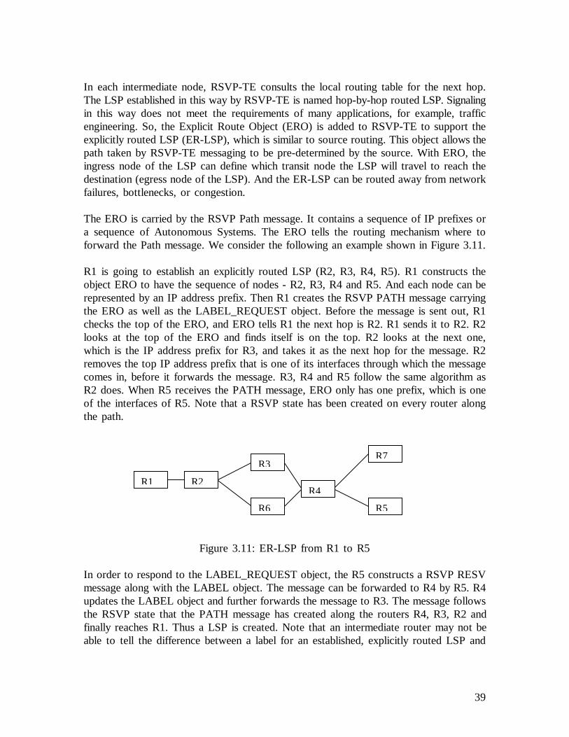
39
In each intermediate node, RSVP-TE consults the local routing table for the next hop.The LSP established in this way by RSVP-TE is named hop-by-hop routed LSP. Signalingin this way does not meet the requirements of many applications, for example, trafficengineering. So, the Explicit Route Object (ERO) is added to RSVP-TE to support theexplicitly routed LSP (ER-LSP), which is similar to source routing. This object allows thepath taken by RSVP-TE messaging to be pre-determined by the source. With ERO, theingress node of the LSP can define which transit node the LSP will travel to reach thedestination (egress node of the LSP). And the ER-LSP can be routed away from networkfailures, bottlenecks, or congestion.
The ERO is carried by the RSVP Path message. It contains a sequence of IP prefixes ora sequence of Autonomous Systems. The ERO tells the routing mechanism where toforward the Path message. We consider the following an example shown in Figure 3.11.
R1 is going to establish an explicitly routed LSP (R2, R3, R4, R5). R1 constructs theobject ERO to have the sequence of nodes - R2, R3, R4 and R5. And each node can berepresented by an IP address prefix. Then R1 creates the RSVP PATH message carryingthe ERO as well as the LABEL_REQUEST object. Before the message is sent out, R1checks the top of the ERO, and ERO tells R1 the next hop is R2. R1 sends it to R2. R2looks at the top of the ERO and finds itself is on the top. R2 looks at the next one,which is the IP address prefix for R3, and takes it as the next hop for the message. R2removes the top IP address prefix that is one of its interfaces through which the messagecomes in, before it forwards the message. R3, R4 and R5 follow the same algorithm asR2 does. When R5 receives the PATH message, ERO only has one prefix, which is oneof the interfaces of R5. Note that a RSVP state has been created on every router alongthe path.
Figure 3.11: ER-LSP from R1 to R5
In order to respond to the LABEL_REQUEST object, the R5 constructs a RSVP RESVmessage along with the LABEL object. The message can be forwarded to R4 by R5. R4updates the LABEL object and further forwards the message to R3. The message followsthe RSVP state that the PATH message has created along the routers R4, R3, R2 andfinally reaches R1. Thus a LSP is created. Note that an intermediate router may not beable to tell the difference between a label for an established, explicitly routed LSP and
R1 R2
R3
R5
R4
R6
R7

40
one for a hop-by-hop routed LSP, as it does not need to make this distinction duringprogramming the data forwarding plane.
If the ERO specifies every node of the LSP or every autonomous system traveled by theLSP, then the LSP is called “strictly” explicitly routed. If the ERO specifies some nodesor some autonomous systems traveled by the LSP, then the LSP is called “loosely”explicitly routed.
GMPLS extends MPLS to support multiple different interfaces. RSVP-TE is alsoextended to support GMPLS signaling. The label request object and label object must begeneralized (see Section 2.4.2 of this report). In [39], the Generalized Label RequestObject (carried by the Path message) and Generalized Label Object (carried by the Resvmessage) are defined. The Generalized Label Request Object allows different transit nodeswith different data links to allocate labels.
When the Path message carrying the Generalized Label Request Object arrives at a node,the node makes sure the label request information (including the switching type, LSPencoding type and generalized payload ID) must be satisfied by the interface throughwhich the traffic comes (incoming interface), the node itself and the interface throughwhich traffic gets forwarded (outgoing interface). The node itself and the interfacesthrough which the traffic is transmitted should be able to support the LSP encoding type.The incoming interface should be able to support the switching type. Note that the labelswitched path (LSP) can be established only between (or through) interfaces of the sameswitching type. Usually only the egress will check the generalized payload ID (because thepayload is transparent to transit nodes). If the egress does not support the payload, theLSP cannot be established. In all of these cases, a RSVP-TE PathErr message isgenerated.
There is no internal structure within a label. If we want nested LSPs (an LSP withinanother LSP), each LSP must be established separately.
The RSVP-TE Resv message carries the generalized label upstream along the reverse pathset up by the Path message. The node that receives the Resv message must verify that thelabel is acceptable. In some situations, the label assigned by the downstream node couldnot be available, for example, an optical cross-connect does not have the wavelength tomodel the label. If the label is not acceptable, the node will generate a RSVP-TE ResvErrmessage.
In GMPLS-RSVP-TE, a procedure for bi-directional LSP set-up is introduced. Theprocedure is added to the establishment of a unidirectional LSP. The Upstream_Labelobject is defined in [39] and it is carried by the RSVP-TE Path message. This object issimilar to the Generalized Label object. It contains a generalized label that is allocated bythe upstream node and used by the downstream node for label swapping. An example isshown in Figure 3.12. The node that receives the Upstream_Label must verify the label isacceptable.

41
Figure 3.12: bi-directional LSP set-up using RSVP-TE
To support explicitly routed LSP in the context of GMPLS, just the IP address or theidentifier of an autonomous system may not be adequate. For example, the LSP set-upneeds to concatenate two LSPs to form an LSP at the edge of two different networks(e.g., an optical network and an IP network). There may be a number of wavelengths in afiber (a link), and a particular wavelength (a label) is needed. The ingress of the LSPneeds to specify the particular label (wavelength). So to support GMPLS signaling, aLabel subobject is defined, which follows the IP address or the identifier of anautonomous system in the ERO. The Label subobject allows the ingress of the LSP tospecify a particular label of a data link.
To improve network survivability, the protection information is considered in GMPLSsignaling. It includes(1) link protection type;(2) indication of whether the path is primary or backup.
The link protection type indicates what link protection capability is desired for the linksconstructing the LSP to be set up (see Section 4.1.3.3 for the link protection types).During LSP signaling in GMPLS, label distribution protocols (RSVP-TE, or LDP) maycarry the protection information. The link protection type in the protection information isone of the TE requirements (or a constraint) for a LSP to be set up. So the LSP set-upwill not continue if the desired link protection cannot be provided.
Router 2Router 1 Router 3
RSVP Path
UpstreamLabel = 3
RSVP Path
UpstreamLabel = 6
RSVP Resv
Label = 4
RSVP Resv
Label = 5
The forwarding entry in Router 2 for direction from R1 to R3
Incoming label 5 Outgoing label 4
The forwarding entry in Router 2 for direction from R3 to R1
Incoming label 6 Outgoing label 3
(1) (2)
(3)(4)

42
Signaling a hierarchical LSPGMPLS supports interfaces that have different switching capabilities. The InterfaceSwitching Capability Descriptor describing the capability is distributed by the routingprotocol throughout the network (see the sectionEnhancements in the Routing Protocolto Support GMPLS), and each node stores this information in the TE link state database(TE-LSDB).
An edge node is the one that connects two different networks constructed by differentnodes, for example, an optical switch that has interfaces providing SONET signals andinterfaces providing WDM capability for photonic cross-connects. When an edge nodesignals an LSP, relying on the Interface Switching Capability Descriptor provided by theTE-LSDB, it can find out whether the interface the signaling comes in has differentswitching capability from the outgoing interface. If so, it knows it may be at the boundaryof two levels of LSP. For example, an edge node may have the Interface SwitchingCapability Descriptor of its interfaces like:
Descriptor for Interface 1:Interface Switching Capability = TDMEncoding = SONETMax Bandwidth[0] = 10 Gbps, for priority 0
Descriptor for Interface 2:Interface Switching Capability = FSC (Fiber Switch Capable)Encoding = Ethernet 802.3Max Bandwidth[0] = 100 Gbps, for priority 0
When the signaling message comes in from interface 1 and the outgoing interface for itwill be interface 2, the edge node understands that a hierarchical LSP will be established(see the example in Figure 3.13). The low-order LSP is tunneled through the high-orderLSP, and multiple low-order LSPs can be aggregated into the high-order LSP.
Figure 3.13: the edge node knows if a hierarchical LSP will be established
Edge node
High-orderLSP
Low-order LSP
The Interface Switching Capabilityof interface 1 is smaller than thatof interface 2
12

43
Here we illustrate how the hierarchical LSP set up is done using RSVP-TE withextensions to support GMPLS. Lower-order LSPs trigger the set-up of a higher-orderLSP. Nodes at the border of two different networks in terms of multiplexing capabilitiesare responsible for establishing higher-order LSPs and aggregate lower-order LSPs. Figure3.14 shows an example. Packet-Switch Capable (e.g., IP packets) LSR 1 and 2 areconnected by a 500 Mb/s Ethernet link, so are LSR 7 and 8. SONET switches and LSRsare connected by OC-12 links; SONET switches and PXCs are connected by OC-192links; PXCs are connected by optical fibers. Note that PXC 4 and 5 may not beconnected directly, e.g., there are other PXCs between the two. Let us assume that theedge PXC has the capability to convert electrical signals to optical signals. They haveinterfaces that can provide SONET signals and interfaces that can provide WDMcapability. An LSP (LSP 1) is going to be established from LSR 1 to LSR 8, whichrequires 500 Mb/s bandwidth.
Figure 3.14: a hierarchical LSP is established between LSR1 and LSR8
We assume that all links have enough bandwidth for the LSPs to be established, and thatthere is no existing LSP between the different nodes. The GMPLS signaling using RSVP-TE starts from LSR1 (see the following figure).
PXC 4 PXC 5SONETSwitch 3
SONETswitch 6
PSCLSR 2
PSCLSR 7
PSCLSR 1
PSCLSR 8
500 Mb/s Ethernet link
SONET OC12 link
SONET OC192 link
Optical fiber
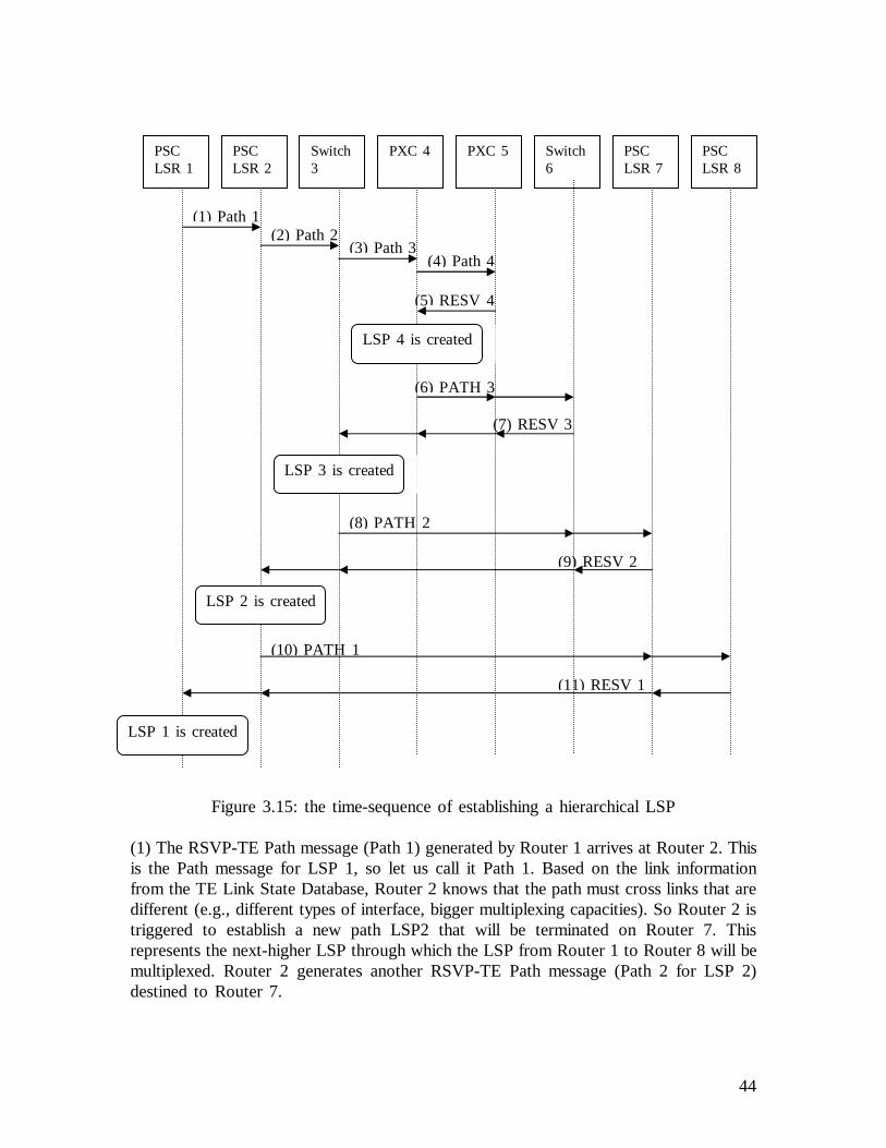
44
Figure 3.15: the time-sequence of establishing a hierarchical LSP
(1) The RSVP-TE Path message (Path 1) generated by Router 1 arrives at Router 2. Thisis the Path message for LSP 1, so let us call it Path 1. Based on the link informationfrom the TE Link State Database, Router 2 knows that the path must cross links that aredifferent (e.g., different types of interface, bigger multiplexing capacities). So Router 2 istriggered to establish a new path LSP2 that will be terminated on Router 7. Thisrepresents the next-higher LSP through which the LSP from Router 1 to Router 8 will bemultiplexed. Router 2 generates another RSVP-TE Path message (Path 2 for LSP 2)destined to Router 7.
PSCLSR 1
PSCLSR 2
Switch3
PXC 4 PXC 5 Switch6
PSCLSR 7
PSCLSR 8
(1) Path 1(2) Path 2
(3) Path 3(4) Path 4
(5) RESV 4
(6) PATH 3
(7) RESV 3
(8) PATH 2
(9) RESV 2
(10) PATH 1
(11) RESV 1
LSP 4 is created
LSP 3 is created
LSP 2 is created
LSP 1 is created

45
(2) Path 2 arrives at SONET Switch 3. Again, Switch 3 finds out that the LSP mustcross different links. Switch 3 is going to establish LSP 3, and it generates RSVP-TEPath message destined to Switch 6 (Path 3).
(3) Path 3 arrives at PXC 4, which triggers PXC 4 to establish LSP 4. So PXC 4generates a Path message destined to PXC 5 (Path 4).
(4) Path 4 arrives at PXC 5.
(5) PXC 5 responds with a RSVP-TE RESV message. Let us call this RESV messageResv 4. Resv 4 arrives at PXC 4, and the LSP 4 is created. LSP 4 is a TE link. It willbe advertised by the routing protocol that runs at this level (e.g., the network constructedby the PXCs) as a lambda-switch-capable link. This LSP is a FA-LSP. The capacity ofthis TE link in the advertisement is the difference between its maximum capacity (e.g., anumber of lambdas) and the share (e.g., one lambda) that has been allocated for the OC-192 bandwidth.
(6) Then PXC 4 continues signaling for LSP 3. The PATH message Path 3 goes on.
(7) Path 3 arrives at Switch 6, and Switch 6 responds with a RSVP-TE RESV message.Let us call it RESV 3.
(8) RESV 3 arrives at Switch 3. LSP 3 is created. LSP 3 is a TE link. It will beadvertised by the routing protocol that runs at this level (e.g., the network constructed byOC-192 switches) as a TDM-switch-capable link. This LSP is a FA-LSP. The capacity ofthis TE link in the advertisement is the difference between its maximum capacity (e.g.,OC-192 bandwidth) and the share (e.g., OC-12 bandwidth) that has been allocated for theLSP 2 being established. Then the LSP 2 set up procedure continues, and Path 2 goes onto Router 7.
(9) Router 7 responds with a RSVP-TE RESV message (RESV 2).
(10) RESV 2 arrives at Router 2 and LSP 2 is created. LSP 2 is a TE link. It will beadvertised by the router protocol that runs at this level (e.g., the network constructed byOC-12 switches) as a TDM-switch-capable link. This LSP is a FA-LSP. The capacity ofthis link in the advertisement is the difference between its maximum capacity (e.g., OC-12bandwidth) and the share (e.g., 500 Mb/s) that has been allocated for the LSP 1 beingestablished. Then the LSP 1 set up procedures continues and Path 1 goes on to Router 9.

46
The hierarchical LSP established in the above example is illustrated in Figure 3.16.
Figure 3.16: the hierarchical LSP in the example
If there is an existing FA-LSP that can satisfy the LSP being established, e.g., itsunreserved bandwidth is bigger than what the LSP being established needs, then the edgenode is responsible for tunneling the low-order LSP onto the existing high-order FA-LSP.In the above example, if LSP 4 has already been established (between PXC 4 and 5)when the Path message for LSP 3 (Path 3) arrives, then LSP 4 is treated as a single linkand the Path 3 message will take PXC 5 as its destination, which is the ending node ofLSP 4.
If the LSP being established is an explicit-routed LSP (ER-LSP), the RSVP-TE Pathmessage carries an Explicit-Routed Object (ERO). A node receiving this messagedetermines if it is the edge node at the boundary of two LSPs. If it is not, theconventional signaling goes on. If it is, it must determine which node is the ending nodeof the high-order LSP (the other edge). Then it must extract from the ERO thesubsequence of hops from itself to the edge of the network. Let us call this subsequenceof hops S1.
An example is shown in Figure 3.17. Node 1, 2 and 3 are part of an optical network.The RSVP-TE Path message carrying the ERO arrives at Node 1. Node 1 checks thenodes in the ERO one by one. From the routing database, it finds out the first 3 nodesstarting from the beginning of the ERO are in the same network.
Figure 3.17: the ERO drives RSVP-TE to establish a hierarchical ER-LSP
LSP 3 LSP 2 LSP 1LSP 4LSP 3LSP 2LSP 1
Node 1
Node 2
Node 3Node 4
ERO
Node 1
Node 2
Node 3
Node 4

47
Then the edge node checks the TE LSDB to see if there is an existing FA-LSP whosehops exactly match S1. If there is, it further checks if the properties of that FA-LSP canmeet the requirements of the LSP being established, e.g., the unreserved bandwidth cansatisfy the LSP being established. If so, the node replaces the hops S1 in the ERO withthe end node of the FA-LSP. In the above example, Let us assume that there is a FA-LSP constructed by Node 1, 2 and 3. Node 1 replaces Node 1, 2 and 3 with Node 3 inthe ERO. Then the destination address of the Path message is set to Node 3, and sentout by Node 1. We can see that the FA-LSP is treated as one link. After that, the TEproperties of the FA-LSP are adjusted, e.g., the unreserved bandwidth is the differencebetween the previous unreserved bandwidth and the requirement of the LSP beingestablished. They are advertised by the routing protocol in the current routing domain,e.g., by OSPF TE-LSA.
If there is no existing FA-LSP or the existing FA-LSPs do not satisfy the requirement ofthe LSP being established, then the edge node will signal a new high-order LSP, whichwill tunnel the low-order LSP. And it would be advertised as a FA-LSP.
The unreserved bandwidth of the FA-LSP is the difference between the maximumreservable bandwidth and what all the multiplexed low-order LSPs request.
The FA-LSP should be torn down if no tunneled LSP is there. There are a number ofways to trigger the FA-LSP tear-down. For example, if the maximum reservablebandwidth is as same as the unreserved bandwidth, then it means the FA-LSP is not beingused, and it should be torn down.
4.3.1.1 Signaling Support for Fault NotificationThe Notification mechanism in the signaling protocol RSVP-TE [26] is dedicated tosupport the fault notification in GMPLS recovery.
Fault notification is to notify the nodes of the failure in the path that are responsible forrecovery. RSVP-TE defines a rapid fault notification mechanism to convey theinformation. The Notification mechanism includes the Notify Request object and theNotify message.
The Notify Request object contains the IP address of the node that should be notified ofthe failure, which is namedNotify Node Address. This address can be configured, orautomatically determined by the protection mechanism. For example, in the 1+1 protectionmechanism, the LSP initiator node is responsible for switching the traffic to the backupLSP when the failure occurs, so theNotify Node Addressshould be that node. The LSPinitiator node may be responsible for attaching this request object in the RSVP-TE Pathmessage. The receiver of such a Path message (transit nodes) should also attach thisobject to the outgoing Path message. So the request is propagated. The terminator nodeof the LSP may respond with a Resv message which also carries the Notify Requestobject for a bi-directional LSP. So the notification may be required in both directions. A

48
node receiving the message records theNotify Node Addressin the protocol soft state(for the RSVP soft state, see the RSVP introduction in the previous sections).
The Notify message provides a mechanism to inform non-adjacent nodes of LSP relatedevents. It is different from the RSVP error message. The RSVP error message must beforwarded one by one along the nodes of the LSP, which is too slow for fault notificationand not necessary. Notify message can be “targeted” to a particular node, e.g., the traffic-switch-over trigger node. By “targeted” it means the destination address of the IP packetcarrying the Notify message is set to the IP address of the target node, which is specifiedby theNotify Node Addressreceived from the Notify Request object. So it does not needto travel along the hops of the original LSP. Because after a failure in the network, thenetwork topology likely has changed and there is another path that is optimal for theNotify message (see Figure 3.18). Nodes receiving a Notify message, which is not thedestination of the message, must forward the message, unmodified, to the target.
Figure 3.18: the Notify message is sent to the targeted node directly
The Notify message contains an ERROR_SPEC object, which specifies the IP address ofthe node that detects the failure or the link that has failed. Optionally it may carry otherRSVP-TE objects that describe the LSP, e.g., the LSP SESSION object. Notify messagesare normally generated only after a Notify Request object has been received.
It is not necessary for the local recovery to use such a notification mechanism. But othermechanisms need it, for example, the end-to-end LSP protection. Section 5 will specifywhich recovery mechanism needs it and when.
4.3.2 GMPLS signaling: CR-LDP with extensionsRSVP-TE, as a label distribution protocol, was built on the existing control protocolRSVP (RFC2205) [40]. Label Distribution Protocol (LDP) [41] was originally designedfor label distribution.
LDP also uses the TLV structure to encode messages, which allows for future extensions.At first, LDP discovers its peers by multicasting an LDP Hello message onto the network.The nodes running LDP that receive the message are triggered to establish an LDP
Node 1 Node 2 Node 3 Node 4
Node 5Node 0
LSP
Notify message
failure

49
session with each other. After the session is successfully created, they become LDP peers,and the session is maintained. Then the LDP peers can exchange label distributionmessages. If there is any error during label distribution, the LDP Notification messagesare used to provide error information, which could tear down the LDP session betweenLDP nodes. LDP uses TCP as the reliable transport mechanism to deliver all messagesexcept the LDP Hello message, which uses UDP.
LDP has been extended to support Traffic Engineering, which is namedConstraint-BasedLSP Setup using LDP(CR-LDP) [42]. CR-LDP defines a new set of TLV structures tosupport explicit routed signaling, traffic parameters, LSP set-up/holding priority, etc. Italso defines a means for resource reservation.
The constraint-based route TLV structure contains a sequence of IP prefixes or asequence of Autonomous Systems. The contents of the constraint-based route TLV arecomputed by CSPF, which tells the routing mechanism where to forward the CR-LDPmessages.
The LSP signaled by CR-LDP is initiated by the head node of the LSP. How it works isillustrated as below.
Router 1 is going to establish an explicit-routed LSP (R1, R2, R3, R4, R5). R1constructs the constraint-based route TLV to have the sequence of nodes (R1, R2, R3,R4, R5). Each node can be represented by an IP address. Then R1 sends out the CR-LDP Label Request message carrying the constraint-based route TLV. Before the messageis sent, R1 checks the top of the TLV, and it finds out that the next hop is R2. R1removes itself from the TLV and sends the message to R2. The Label Request messagemay carry the Traffic Parameter TLV, which specifies the traffic parameters to be sent. Ifso, R1 reserves the resource before the message is sent out. R2 receiving the messagealso checks the top of the TLV, and it finds out R3 is the next hop. R2 removes theaddress of R2 from the TLV and sends out the Label Request message. It may alsoreserves the resource for the LSP if the Traffic Parameter TLV is carried. R3, R4, andR5 follow the same algorithm as R2 does. When R5 receives the message, the TLV onlyhas one address, which is R5 itself. Along the message path, the LDP protocol stateshould be created.
R5, as the ending node of the LSP, programs the label forwarding table, reserves theresource if needed, and responds with a CR-LDP Label Mapping message, which carries a
R1 R2
R3
R5
R4
Figure 3.3.2.1: ER-LSP from R1 to R5
R6
R7

50
Label TLV. The Label TLV contains the label that the downstream node wants theupstream node to use. The protocol state on the node tells R5 to send the Label Mappingmessage to R4. R4, R3 and R2 do the same thing as R5 does. R1, as the head node ofthe LSP, does not need to allocate label any more, but simply receives the label andprograms the label forwarding table.
The head node of an LSP transmits a Label Release message to a peer when it is nolonger needs a label previously received from that peer. This takes place when the LSP istorn down (see the following figure).
Figure 3.19: LSP (R1, R2, R3) is torn down by Label Release message
Unlike the RSVP-TE, CR-LDP is not a soft state protocol. By this it means the LSPcreated by CR-LDP does not need the signaling refresh periodically. The LSP must betorn down explicitly.
CR-LDP is also being extended to support GMPLS [43]. The information that is neededto support generalized label in RSVP-TE is also needed for CR-LDP. For example, thelabel format in the Label TLV is also generalized to support different types of “label”,e.g., the port number, wavelength, etc.
CR-LDP is also required to support bi-directional LSP set up. The idea is to add theUpstream Label TLV in the Label Request message (see Figure 3.20).
Figure 3.20: CR-LDP signals a bi-directional LSP
R 1 R 2 R3(1) Label Release (2) Label Release
Router 2Router 1 Router 3
CR-LDP LabelRequest
Upstream Label= 3
CR-LDP LabelRequest
Upstream Label= 6
CR-LDP LabelMapping
DownstreamLabel = 4
CR-LDP LabelMapping
DownstreamLabel = 5
(1) (2)
(3)(4)

51
To support explicitly routed LSP in the context of GMPLS, just the IP address or theidentifier of an autonomous system may not be adequate. RSVP-TE defines the Labelobject as a sub-object in the ERO, and CR-LDP defines the Explicit Label Control TLVas a sub-TLV following the IP address or the Autonomous System ID in the constraint-based route TLV.
In order to improve network survivability, the protection information is considered inGMPLS signaling. Like RSVP-TE, CR-LDP defines the Protection TLV, which includes:(1) link protection type;(2) indication of whether the path is primary or backup.
CanCR-LDP with extensions[25] do whateverRSVP-TE with extensions[26] can do soas to support GMPLS signaling? No, as this report is being written. The RSVP-TE [26]has got the fault notification mechanism (see Section 4.3.1.1) to notify a responsible nodewhen a link/node failure occurs. But CR-LDP [25] does not have a similar mechanismyet. CR-LDP [25] has its own Notification message, but it does not provide the samefunction as the one does in RSVP-TE.
From now on in this report, RSVP-TE is used to illustrate the GMPLS signaling supportfor LSP protection/restoration.
4.4 The Hello ProtocolIn fact, there is no protocol called Hello. OSPF, RSVP-TE, LMP and other protocolsdefine a software method to detect failures, which is the Hello messaging. The idea of theHello messaging is simple. Two nodes exchange a short message named Helloperiodically. The interval can be configured, e.g., the recommended interval for OSPFHello is 5 ms (see RFC2328). If a number of messages are missed, e.g., 4, then the nodecan determine that the other node is down or the link between the two is broken.
Although many protocols provide this method to detect failures, using software to detecta failure is very slow and usually does not meet real-time application requirements.Furthermore, it is difficult for the software detection to deal with the shaking problem. Anode does not receive OSPF Hello messages from its neighbor for several times, and itdetermines its neighbor is down. But just after that it can receive Hello again due to theunstable situation in the network. The problem keeps repeating like that for a while,which is calledshaking.
However, the software fault detection is still useful in some situations. An example is theEthernet, where nodes are connected by a bus (multiple access media). A node can detectits peer’s fault by the Hello messaging.
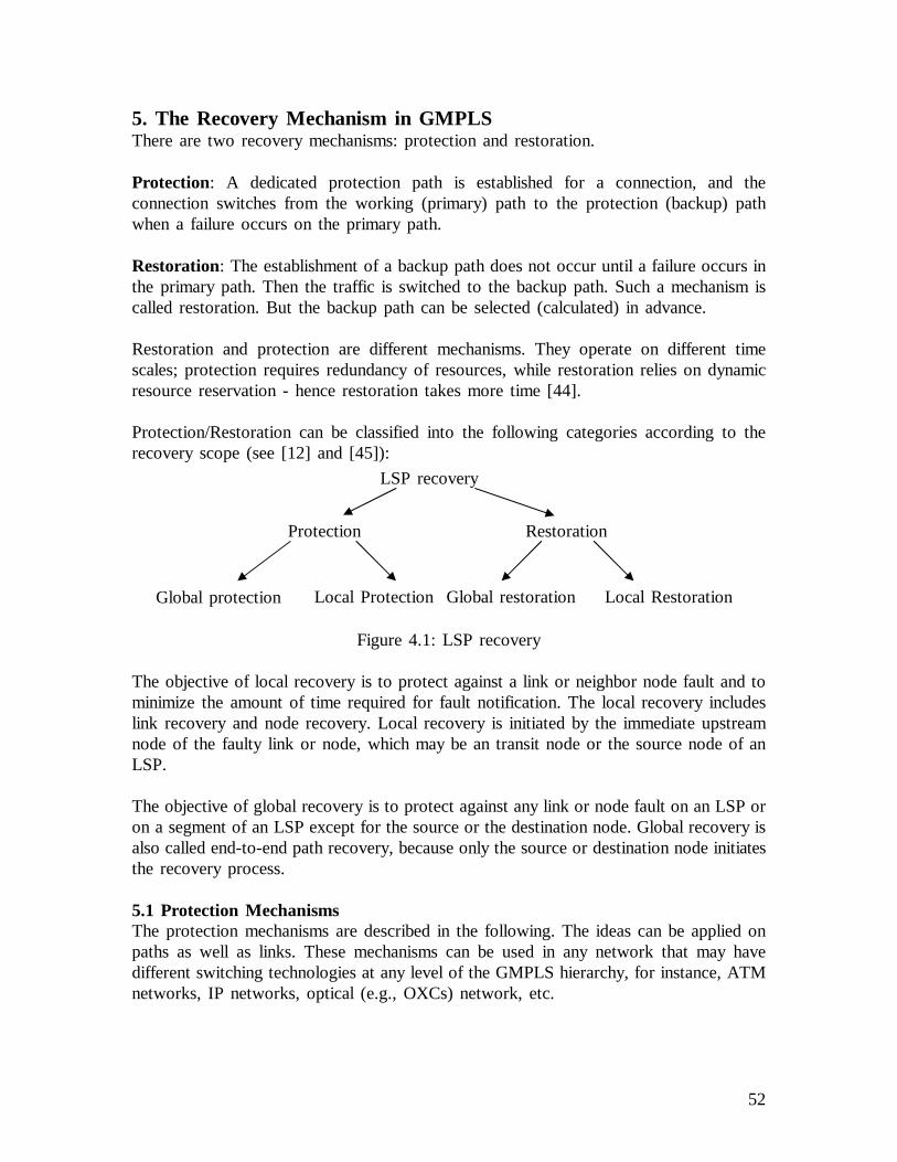
52
5. The Recovery Mechanism in GMPLSThere are two recovery mechanisms: protection and restoration.
Protection: A dedicated protection path is established for a connection, and theconnection switches from the working (primary) path to the protection (backup) pathwhen a failure occurs on the primary path.
Restoration: The establishment of a backup path does not occur until a failure occurs inthe primary path. Then the traffic is switched to the backup path. Such a mechanism iscalled restoration. But the backup path can be selected (calculated) in advance.
Restoration and protection are different mechanisms. They operate on different timescales; protection requires redundancy of resources, while restoration relies on dynamicresource reservation - hence restoration takes more time [44].
Protection/Restoration can be classified into the following categories according to therecovery scope (see [12] and [45]):
Figure 4.1: LSP recovery
The objective of local recovery is to protect against a link or neighbor node fault and tominimize the amount of time required for fault notification. The local recovery includeslink recovery and node recovery. Local recovery is initiated by the immediate upstreamnode of the faulty link or node, which may be an transit node or the source node of anLSP.
The objective of global recovery is to protect against any link or node fault on an LSP oron a segment of an LSP except for the source or the destination node. Global recovery isalso called end-to-end path recovery, because only the source or destination node initiatesthe recovery process.
5.1 Protection MechanismsThe protection mechanisms are described in the following. The ideas can be applied onpaths as well as links. These mechanisms can be used in any network that may havedifferent switching technologies at any level of the GMPLS hierarchy, for instance, ATMnetworks, IP networks, optical (e.g., OXCs) network, etc.
Protection
Local ProtectionGlobal protection Local RestorationGlobal restoration
LSP recovery
Restoration
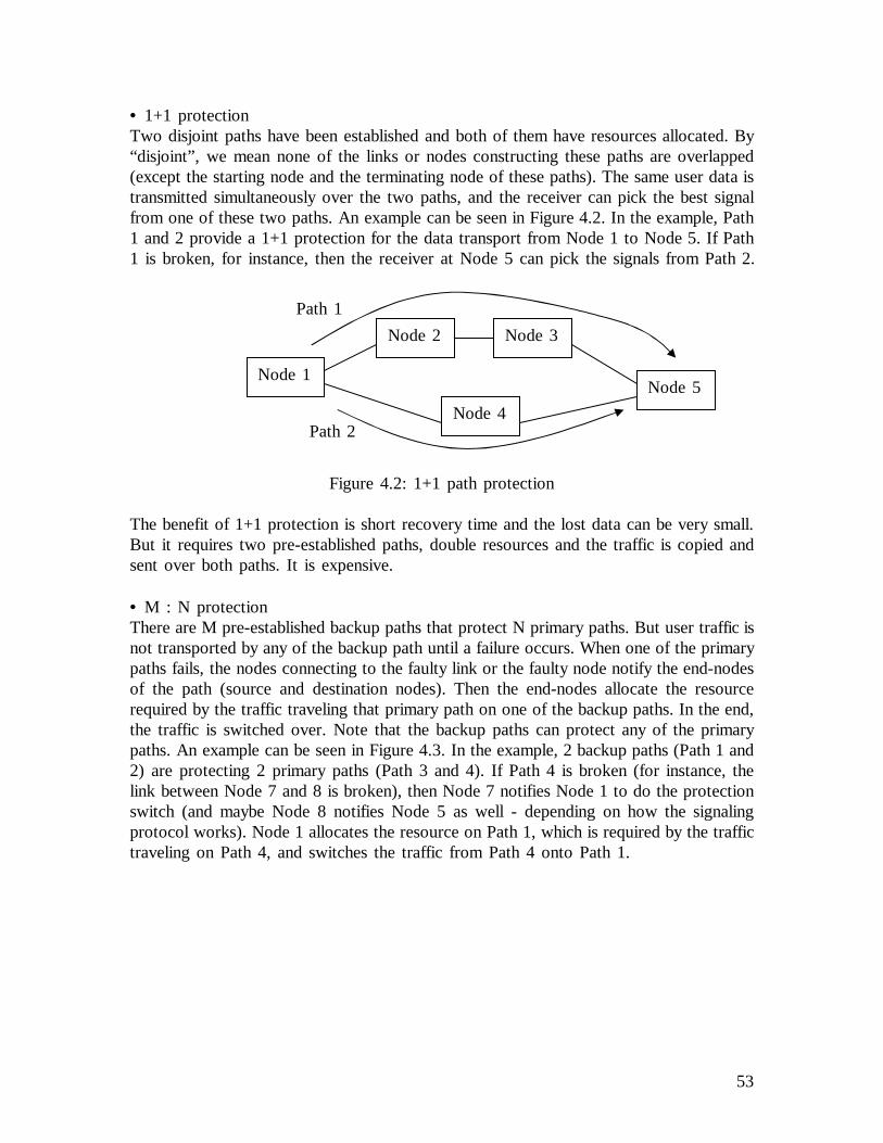
53
• 1+1 protectionTwo disjoint paths have been established and both of them have resources allocated. By“disjoint”, we mean none of the links or nodes constructing these paths are overlapped(except the starting node and the terminating node of these paths). The same user data istransmitted simultaneously over the two paths, and the receiver can pick the best signalfrom one of these two paths. An example can be seen in Figure 4.2. In the example, Path1 and 2 provide a 1+1 protection for the data transport from Node 1 to Node 5. If Path1 is broken, for instance, then the receiver at Node 5 can pick the signals from Path 2.
Figure 4.2: 1+1 path protection
The benefit of 1+1 protection is short recovery time and the lost data can be very small.But it requires two pre-established paths, double resources and the traffic is copied andsent over both paths. It is expensive.
• M : N protectionThere are M pre-established backup paths that protect N primary paths. But user traffic isnot transported by any of the backup path until a failure occurs. When one of the primarypaths fails, the nodes connecting to the faulty link or the faulty node notify the end-nodesof the path (source and destination nodes). Then the end-nodes allocate the resourcerequired by the traffic traveling that primary path on one of the backup paths. In the end,the traffic is switched over. Note that the backup paths can protect any of the primarypaths. An example can be seen in Figure 4.3. In the example, 2 backup paths (Path 1 and2) are protecting 2 primary paths (Path 3 and 4). If Path 4 is broken (for instance, thelink between Node 7 and 8 is broken), then Node 7 notifies Node 1 to do the protectionswitch (and maybe Node 8 notifies Node 5 as well - depending on how the signalingprotocol works). Node 1 allocates the resource on Path 1, which is required by the traffictraveling on Path 4, and switches the traffic from Path 4 onto Path 1.
Node 1
Node 2 Node 3
Node 4
Node 5
Path 1
Path 2

54
Figure 4.3: 2:2 path protection
It is not recommended that the links constructing different primary paths belong to thesame Shared Risk Link Group. For example, both primary path (L1, L2, L3) and (L4, L2,L5) have the same link L2, and they would better not share the same backup path.Otherwise, if L2 goes down, it is possible that one of the primary paths would not haveany protection.
• 1 : N protectionIt is a special case of M : N protection - only one pre-established backup path providesprotection for N primary paths. Let us look at Figure 4.3 again, and assume that Path 1is protecting other paths. If the link between Node 7 and Node 8 is broken, Node 7notifies Node 1 (and maybe Node 8 notifies Node 5 as well) to do the protection switch.Then Node 1 allocates resource required on Path 1, and switches the traffic onto Path 1.
If there are two primary paths that are broken simultaneously, then a policy is used todecide which one will get protected. One of the policies is taking priorities. For example,Path 3 and 4 are broken, if the traffic traveling on Path 3 is deemed to have higherpriority than the traffic traveling on Path 4, then Path 3 will get protected by Path 1.Another simple policy can be First-Come-First-Service.
The links constructing the primary path should not belong to the same Shared Risk LinkGroup. Otherwise, if the link constructing both of the paths is cut, then one of theprimary paths does not have any protection.
• 1 : 1 protectionIt is also a special case of M : N protection - one dedicated backup path is pre-established for one primary path. For optimization, the resource may be pre-allocated if itis known in advance. But the user traffic is not inserted onto the backup path. So theresource pre-allocated on the backup path may be used by other LSPs that have lower
Node 1
Node 2 Node 3
Node 4Node 5
Path 1
Path 2
Node 6
Node 7Node 8
Path 4Path 3
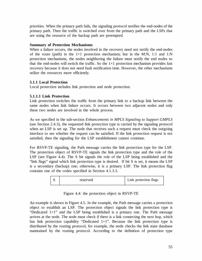
55
priorities. When the primary path fails, the signaling protocol notifies the end-nodes of theprimary path. Then the traffic is switched over from the primary path and the LSPs thatare using the resource of the backup path are preempted.
Summary of Protection MechanismsWhen a failure occurs, the nodes involved in the recovery need not notify the end-nodesof the route (path) in the 1+1 protection mechanism; but in the M:N, 1:1 and 1:Nprotection mechanisms, the nodes neighboring the failure must notify the end nodes sothat the end-nodes will switch the traffic. So the 1+1 protection mechanism provides fastrecovery because it does not need fault notification time. However, the other mechanismsutilize the resources more efficiently.
5.1.1 Local ProtectionLocal protection includes link protection and node protection.
5.1.1.1 Link ProtectionLink protection switches the traffic from the primary link to a backup link between thesame nodes when link failure occurs. It occurs between two adjacent nodes and onlythese two nodes are involved in the whole process.
As we specified in the sub-sectionEnhancements in MPLS Signaling to Support GMPLS(see Section 2.4.3), the requested link protection type is carried by the signaling protocolwhen an LSP is set up. The node that receives such a request must check the outgoinginterface to see whether the request can be satisfied. If the link protection request is notsatisfied, then the signaling for the LSP establishment cannot continue.
For RSVP-TE signaling, the Path message carries the link protection type for the LSP.The protection object of RSVP-TE signals the link protection type and the role of theLSP (see Figure 4.4). The S bit signals the role of the LSP being established and the“link flags” signal which link protection type is desired. If bit S is set, it means the LSPis a secondary (backup) one; otherwise, it is a primary LSP. The link protection flagcontains one of the codes specified in Section 4.1.3.3.
Figure 4.4: the protection object in RSVP-TE
An example is shown in Figure 4.5. In the example, the Path message carries a protectionobject to establish an LSP. The protection object signals the link protection type is“Dedicated 1+1” and the LSP being established is a primary one. The Path messagearrives at the node. The node must check if there is a link connecting the next hop, whichhas link protection capability “Dedicated 1+1”. Because the link protection type isdistributed by the routing protocol, for example, the node checks the link state databasemaintained by the routing protocol. According to the definition of protection type
Link protection flagsS reserved
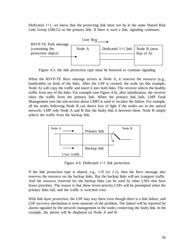
56
Dedicated 1+1, we know that the protecting link must not be in the same Shared RiskLink Group (SRLG) as the primary link. If there is such a link, signaling continues.
Figure 4.5: the link protection type must be honored to continue signaling
When the RSVP-TE Resv message arrives at Node A, it reserves the resource (e.g.,bandwidth) on both of the links. After the LSP is created, the node (in this example,Node A) will copy the traffic and insert it into both links. The receiver selects the healthytraffic from any of the links. For example (see Figure 4.6), after initialization, the receivertakes the traffic from the primary link. When the primary link fails, LMP FaultManagement (see the sub-section about LMP) is used to localize the failure. For example,all the nodes following Node B can detect loss of light if the nodes are in the opticalnetwork. LMP tells Node A and B that the faulty link is between them. Node B simplyselects the traffic from the backup link.
Figure 4.6: Dedicated 1+1 link protection
If the link protection type is shared, e.g., 1:N (or 1:1), then the Resv message alsoreserves the resource on the backup links. But the backup links will not transport traffic.And the resource reserved for the backup links can be used by other LSPs that havelower priorities. The reason is that these lower-priority LSPs will be preempted when theprimary links fail, and the traffic is switched over.
With link layer protection, the LSP may stay there even though there is a link failure, andLSP recovery mechanism is even unaware of the problem. The failure will be reported byalarms signaled by the network management in the nodes connecting the faulty link. In theexample, the alarms will be displayed on Node A and B.
Node A Node B (nexthop of A)
Dedicated 1+1 linkRSVP-TE Path message(containing theprotection object)
User flow
Node A Node B
User traffic
Primary link
Backup link

57
Summary of Link ProtectionBecause the point that initiates the recovery is close to the failure, there is no need tohave fault notification - it provides fast recovery. Only the nodes connecting the faultylink are involved in the recovery. And it does not require any changes in the GMPLSLSP.
But the protection ability is limited. If the entire LSP requires link layer protection, it isexpensive and the control becomes a big overhead, because every node along the wholeLSP needs to keep monitoring links.
Therefore, usually link layer protection is only used in an area that is deemed to beunreliable.
5.1.1.2 Node ProtectionIn fact, there is no protection mechanism in the GMPLS LSP level that is dedicated tolocally provide single node failure protection. If some nodes in a network are deemed tobe unreliable, then the path computation should compute a path that will work aroundthose nodes. On the other hand, global path protection and restoration can recover thetraffic affected by node failure. These mechanisms will be introduced later.
5.1.2 Global ProtectionFrom the previous sub-section, we can see that link layer protection provides the linkprotection under the GMPLS LSP layer.
With the end-to-end path protection (global protection), multiple disjoint hierarchical LSPsare pre-computed and established between the initiator and the terminator nodes of aclient LSP. Dedicated resources are allocated for these LSPs. So the nodes and links ofthe entire primary hierarchical LSP are protected except for the initiator and terminatornodes. In order to avoid the contention of multiple layer protection mechanisms, the LSPsmay require “unprotected” Link Protection Type during signaling. Thus the protection isonly built on the MPLS-based layer and contention will not occur. When a failure occurs,the nodes that detect the failure notify the end nodes (the initiator and terminator nodes).The end nodes initiate switching the traffic to the alternate path.
The illustration is shown in Figure 4.7. The logical view of the 1:1 LSP protection isshown in the figure. The LSP (Node 1, Node 3, Node 5, Node 7) is the primary one;LSP (Node1, Node2, Node4, Node6, Node8, Node7) is the backup. Both may behierarchical LSPs, e.g., the link (Node3, Node5) is a FA-LSP (TE link), so is link(Node4, Node6). Traffic is sent along the primary LSP. If a failure occurs, the nodes thatdetect the failure notify the end nodes: Node 1 and 7, then the end nodes will switch thetraffic to the backup LSP.
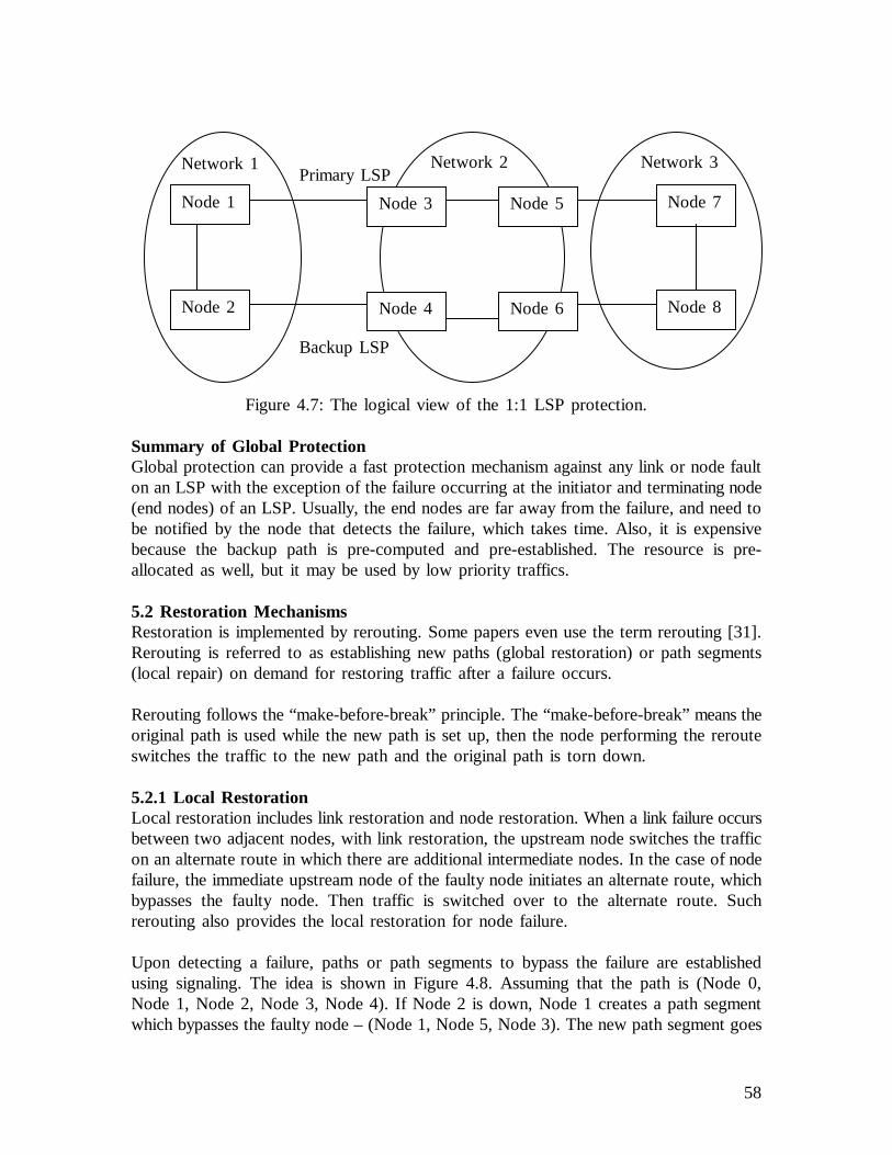
58
Figure 4.7: The logical view of the 1:1 LSP protection.
Summary of Global ProtectionGlobal protection can provide a fast protection mechanism against any link or node faulton an LSP with the exception of the failure occurring at the initiator and terminating node(end nodes) of an LSP. Usually, the end nodes are far away from the failure, and need tobe notified by the node that detects the failure, which takes time. Also, it is expensivebecause the backup path is pre-computed and pre-established. The resource is pre-allocated as well, but it may be used by low priority traffics.
5.2 Restoration MechanismsRestoration is implemented by rerouting. Some papers even use the term rerouting [31].Rerouting is referred to as establishing new paths (global restoration) or path segments(local repair) on demand for restoring traffic after a failure occurs.
Rerouting follows the “make-before-break” principle. The “make-before-break” means theoriginal path is used while the new path is set up, then the node performing the rerouteswitches the traffic to the new path and the original path is torn down.
5.2.1 Local RestorationLocal restoration includes link restoration and node restoration. When a link failure occursbetween two adjacent nodes, with link restoration, the upstream node switches the trafficon an alternate route in which there are additional intermediate nodes. In the case of nodefailure, the immediate upstream node of the faulty node initiates an alternate route, whichbypasses the faulty node. Then traffic is switched over to the alternate route. Suchrerouting also provides the local restoration for node failure.
Upon detecting a failure, paths or path segments to bypass the failure are establishedusing signaling. The idea is shown in Figure 4.8. Assuming that the path is (Node 0,Node 1, Node 2, Node 3, Node 4). If Node 2 is down, Node 1 creates a path segmentwhich bypasses the faulty node – (Node 1, Node 5, Node 3). The new path segment goes
Network 1 Network 2 Network 3
Node 1
Node 2
Node 3
Node 4
Node 7
Node 8
Primary LSP
Backup LSP
Node 5
Node 6
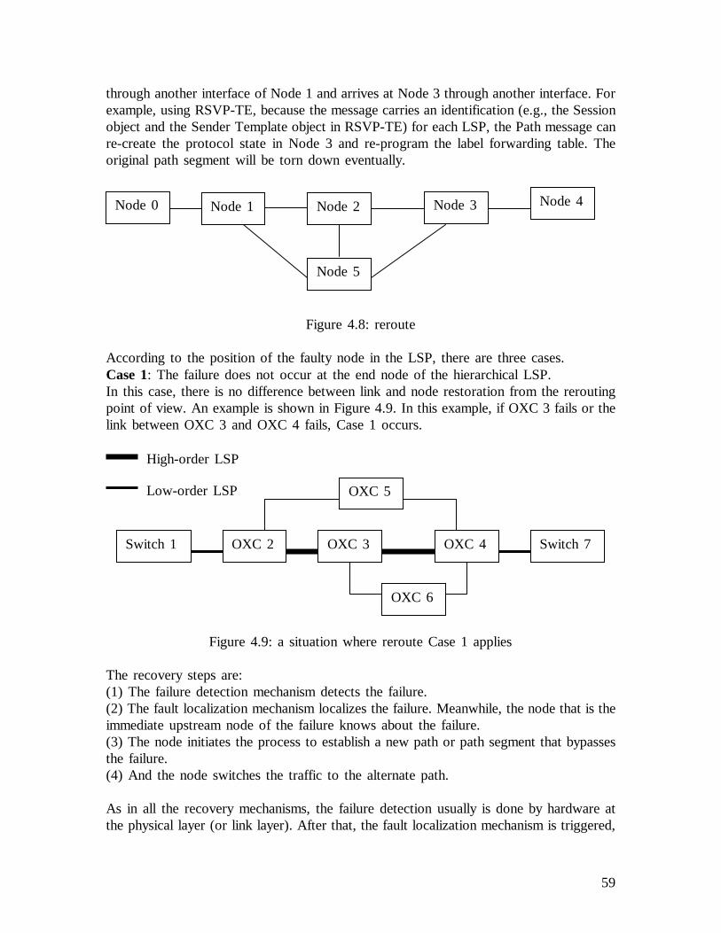
59
through another interface of Node 1 and arrives at Node 3 through another interface. Forexample, using RSVP-TE, because the message carries an identification (e.g., the Sessionobject and the Sender Template object in RSVP-TE) for each LSP, the Path message canre-create the protocol state in Node 3 and re-program the label forwarding table. Theoriginal path segment will be torn down eventually.
Figure 4.8: reroute
According to the position of the faulty node in the LSP, there are three cases.Case 1: The failure does not occur at the end node of the hierarchical LSP.In this case, there is no difference between link and node restoration from the reroutingpoint of view. An example is shown in Figure 4.9. In this example, if OXC 3 fails or thelink between OXC 3 and OXC 4 fails, Case 1 occurs.
Figure 4.9: a situation where reroute Case 1 applies
The recovery steps are:(1) The failure detection mechanism detects the failure.(2) The fault localization mechanism localizes the failure. Meanwhile, the node that is theimmediate upstream node of the failure knows about the failure.(3) The node initiates the process to establish a new path or path segment that bypassesthe failure.(4) And the node switches the traffic to the alternate path.
As in all the recovery mechanisms, the failure detection usually is done by hardware atthe physical layer (or link layer). After that, the fault localization mechanism is triggered,
High-order LSP
Low-order LSP
OXC 2 OXC 3 OXC 4Switch 1 Switch 7
OXC 5
OXC 6
Node 1 Node 2 Node 3
Node 5
Node 4Node 0

60
which can find out where the failure is. For example, LMP fault management (see theSection 4.2) can localize a link failure. The fault localization mechanism does not stoprunning until the node that is the immediate upstream node of the failure finds out thefailure. So there is no need to have explicit fault notification. For a faulty node, theimmediate upstream node of the faulty node detects the problem. Then signaling is usedto create a reroute.
Using RSVP-TE, the reroute initiator node sends out the Path refresh message, which willconsult the routing component for a feasible route. In the example in Figure 4.9, if OXC3 is down, OXC 2 detects the failure, e.g., by OSPF Hello messaging or other means,and sends out the Path refresh message, which can travel to OXC 5 to get to OXC 4.OXC 4 responds with a Resv refresh message, and the LSP between OXC 2 and OXC 4is fixed. If the link between OXC 3 and OXC 4 is broken, LMP fault management canlocalize the failure. OXC 3 sends out the Path refresh message, which can travel to OXC6 to get to OXC 4 and repairs the FA-LSP.
Case 2: The terminator node of a FA-LSP fails. An example is shown in Figure 4.10. Inthis example, if OXC 4 fails, Case 2 occurs.
Figure 4.10: the situation where reroute Case 2 applies
Note that the high-order LSP between OXC 2 and 4 is an FA-LSP, which tunnels low-order LSPs. As the OXC 4 is the terminator node of the FA-LSP, it is impossible torebuild this FA-LSP so that it meets the requirements of the tunneled LSPs. For example,the tunneled low-order LSPs go to multiple different destinations after the FA-LSP, like,Switch 6, Switch 7, etc. The FA-LSP does not know the information, so there is nosense for OXC 2 to reroute FA-LSP and there is no need to repair the FA-LSP.
However, local recovery can still be useful. The OXC 2 is the node that tunnels(aggregates) a number of low-order LSPs. If the FA-LSP is broken, the OXC 2 cantrigger all the tunneled LSPs to reroute individually. For example, a low-order LSP,which was tunneled by the FA-LSP at OXC 2, can re-establish a path segment thatbypasses the failure and reaches the desired destination, e.g., Switch 6. Let us see how itworks.
High-order LSP
Low-order LSP
OXC 2 OXC 3 OXC 4Switch 1 Switch 6
Switch 7

61
When OXC 4 fails, it is as if the “link”FA-LSPfailed. Because OXC 2 and OXC 4 havethe “Forwarding Adjacency” (FA), OXC 2 should be notified according to the linkrestoration mechanism. The Notification mechanism of RSVP-TE is useful here.
OXC 2, as the initiator node of the FA-LSP, can attach the Notify Request object to thePath message when the FA-LSP is established, and the target node address in the objectis OXC 2 itself. When OXC 4 fails, fault detection, e.g., OSPF Hello messaging, enablesOXC 3 to detect the neighbor failure. Then OXC 3 notifies OXC 2.
Another way is by administration. During signaling, OXC 3 knows that it is thepenultimate node of the FA-LSP, e.g., routing tells OXC 3 that it is directly connected toOXC 4. Let us assume that we have such an administration policy that the penultimatenode of the FA-LSP must notify the initiator node of the LSP. The Notify messagedestination address can be configured. In the example, OXC 3 can send out the RSVP-TENotify message targeted to the initiator node - OXC 2 in this example.
After the initiator node of the FA-LSP is notified, it tells all the tunneled low-order LSPsto re-establish the LSP segment (e.g., maybe another hierarchical LSP) that bypasses thefault.
Case 3: The initiator node of a FA-LSP fails.If the initiator node of a client LSP fails, then there is no general LSPprotection/restoration mechanism.
If the initiator node of a FA-LSP fails, then the immediate upstream node of the faultynode will re-establish a new LSP segment that bypasses the failure. An example is shownin Figure 4.11.
Figure 4.11: the situation where reroute Case 3 applies
In the example, a low-order LSP goes through (Switch 1, OXC 2, OXC 3, OXC 4,Switch 6). And the high-order LSP (FA-LSP) goes through (OXC 2, OXC 3, OXC 4). IfOXC 2 is down, Switch 1 detects the neighbor failure, and it will initiate the reroute. Itmay trigger establishing another high-order LSP (FA-LSP) that bypasses OXC 2, e.g.,
OXC 2 OXC 3 OXC 4Switch 1 Switch 6
OXC 5
High-order LSP
Low-order LSP

62
FA-LSP (OXC5, OXC3, OXC4). And the low-order LSP is tunneled by the new FA-LSP.
The problem of multiple layer protection contention can also occur when using localrestoration. For example, the link between two adjacent nodes is broken. If there is linklayer protection there, e.g., that link isDedicated 1+1protected link, it can provide fasterrecovery and the reroute should not be needed. So a coordination mechanism should beneeded, e.g., the hold-off timer.
In the above cases, how does the reroute initiator node find the next hop to send out thesignaling message so as to create the reroute path segment? The conventional RSVP [40]must consult the routing table. It expects that the changed topology has been shown inthe routing table. But this does not happen right away after the fault in the network. Sothe conventional reroute to locally repair the link/node failure suffers packet loss. Let ussee what is the problem.
When a link/node failure occurs in a network, routing protocols exchange the routingmessages in the network to reflect a new topology. The routing information on differentnodes may be temporarily inconsistent. And even a forwarding loop could be created. Thesituation causes packet loss. The longer the inconsistency lasts, the more packets arelikely to be lost. The time consists of three periods: (1) the time the node needs to detectthe failure, (2) the time a node needs to distribute the information across the network and(3) the time to reconstruct the routing table. Among these factors, period (2) is the majorone (see [46]). To reduce the time it takes to detect link failure, we can use mechanismsin the link layer, e.g., in SONET, it is possible to detect link failure in less than 10 ms bySONET-specific mechanisms, such as Loss of Frame detection. But with regard to (2),the distribution nature of IP routing and the need for all the nodes to converge toconsistent routing place limitations on how much (2) can be reduced. In practice, the timeto converge within a single routing domain may be on the order of seconds. That meansthe packet loss may last on the order of seconds. Let us have an example (see Figure4.12). Let us assume that the link between Router 1 and 2 is broken. Router 1 detectsthe failure. With the current routing table, Router 1 can find out that there is analternative path (R1, R3, R4, R5, R2). Then, to create the reroute path segment, Router1 sends out the RSVP-TE Path refresh message destined for Router 2 to Router 3. Butdue to the routing information distribution delay (2) mentioned above, Router 3 things R1should be the next hop because it only takes 2 hops (R1 and R2). So Router 3 forwardsthe message back to Router 1. Thus the forwarding loop is created for a short period oftime. The message is discarded. Packets would be lost for seconds and signaling fails untilthe next refresh time.
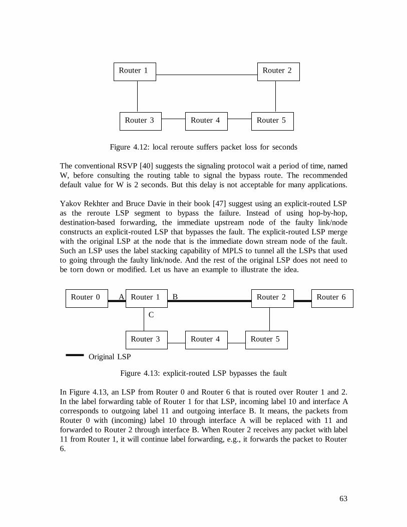
63
Figure 4.12: local reroute suffers packet loss for seconds
The conventional RSVP [40] suggests the signaling protocol wait a period of time, namedW, before consulting the routing table to signal the bypass route. The recommendeddefault value for W is 2 seconds. But this delay is not acceptable for many applications.
Yakov Rekhter and Bruce Davie in their book [47] suggest using an explicit-routed LSPas the reroute LSP segment to bypass the failure. Instead of using hop-by-hop,destination-based forwarding, the immediate upstream node of the faulty link/nodeconstructs an explicit-routed LSP that bypasses the fault. The explicit-routed LSP mergewith the original LSP at the node that is the immediate down stream node of the fault.Such an LSP uses the label stacking capability of MPLS to tunnel all the LSPs that usedto going through the faulty link/node. And the rest of the original LSP does not need tobe torn down or modified. Let us have an example to illustrate the idea.
Figure 4.13: explicit-routed LSP bypasses the fault
In Figure 4.13, an LSP from Router 0 and Router 6 that is routed over Router 1 and 2.In the label forwarding table of Router 1 for that LSP, incoming label 10 and interface Acorresponds to outgoing label 11 and outgoing interface B. It means, the packets fromRouter 0 with (incoming) label 10 through interface A will be replaced with 11 andforwarded to Router 2 through interface B. When Router 2 receives any packet with label11 from Router 1, it will continue label forwarding, e.g., it forwards the packet to Router6.
Router 1 Router 2
Router 3 Router 4 Router 5
Router 1 Router 2
Router 3 Router 4 Router 5
Original LSP
Router 0 Router 6A B
C

64
Let us assume that the link between Router 1 and Router 2 is broken. Router 1 detectsthe link failure, and it can construct an explicit-routed LSP right away, which is (Route 1,Router 3, Router 4, Router 5, Router 2), because its routing table tells it that there issuch a route from Router 1 to Router 2. The topology change does not have an effect onconstructing such an explicit-routed LSP. Now how to tunnel the original LSP? The Pathmessage carries the ERO containing (Router 1, Router 3, Router 4, Router 5, Router 2),which specifies the explicit-routed LSP. The ERO drives Path message from Router 1,Router 3, Router 4, Router 5, and finally to Router 2. Router 2 responds with a Resvmessage, which allocates label 20 to Router 5. Similarly, Router 5 allocates label 21 toRouter 4, Router 4 allocates label 22 to Router 3, and Router 3 allocates label 23 toRouter 1. Router 1, receiving the label, re-programs the label forwarding table. First, itadds one more operation to the label forwarding process, which is to push label 23 on thepacket that is from Router 0, and this operation is after replacing label 10 with 11 on thepacket. Second, the outgoing interface is not B any more, but C. Router 2, as the endingnode, may support penultimate hop popping.
Now, assuming that the packet with label 10 arrives at Router 1. Router 1 replaces label10 with label 11 (as it did before the link failure), furthermore it pushes 23 on top oflabel 11. And it forwards the packet to interface C. Router 3 forwards the packet toRouter 4 by replacing label 23 with 22. Similarly, Router 4 forwards the packet to Router5 by replacing label 22 with 21. Router 5 forwards the packet to Router 2 by replacinglabel 21 with 20. When the packet arrives at Router 2, label 20 is striped off, and thelabel 11 becomes the top label. As before, Router 2 understands how to forward packetswith label 11. The label allocation can be seen in Figure 4.14.
Figure 4.14: explicit-routed LSP bypasses the fault
The advantage of this solution is that the immediate upstream node of the fault does notneed to wait for the routing information distribution or routing database synchronization.And it does not need to wait for reconstructing the routing table because the routing
Router 1 Router 2
Router 3
Router 4
Router 5
Original LSP
Router 0 Router 6A B
C
20
2122
23

65
database can still tell the reroute initiator node if there is another route to repair the patheven after the link/node failure. Note that the reroute initiator node is the immediateupstream node of the failure. Thus, the waiting period of time (2) and (3) suffered byconventional IP routing can be eliminated. So this solution, which uses explicit-routedLSP to reroute, is faster.
From the above analysis, we can also see that this solution does not need to change thecurrent signaling protocols, but it requires the nodes implement the intelligence to supportthis solution.
Summary of Local ReroutingLocal restoration eliminates the need to propagate fault information across networks. Butits application is limited.
As specified in Section 4.3.1 of this report, an explicitly routed LSP (ER-LSP) is pre-computed, which usually meets some traffic engineering goals. If a user’s LSP is an ER-LSP, it is highly desired not to be rerouted. For example, the user’s ER-LSP can routeaway from network congestion and bottlenecks. The local restoration mechanism worksfor the hop-by-hop routed LSP recovery very well, and it also works for the looselyspecified portion of an ER-LSP, but not for a strictly routed ER-LSP. The local reroutemechanism is dynamic – it repairs the LSP by bypassing the failure after the failureoccurs, and the new LSP travels some nodes/links that may not be desired. Such an LSPmay not be optimal. Therefore, if we use local reroute mechanism for a user’s ER-LSP,then after the local repair for a strict ER-LSP or the strictly specified portion of a looseER-LSP, the initiator node of the LSP must be notified. And it should re-compute theLSP, and establish a new ER-LSP to meet the original requirements.
Using conventional local reroute takes a lot of time to wait for the routing informationsynchronization, and the local reroute using Yakov Rekhter and Bruce Davie’s proposal(see [47]) provides a solution to solve the problem. But the signaling for creating thereroute path still takes time.
Because of the network topology, local repair may not succeed.
5.2.2 Global RestorationWith global (end-to-end) path restoration, the backup path is not established until thefailure on the path occurs. After the failure is detected, the initiator node of the faultyLSP is notified of the failure. And it establishes the alternate path destined for thedestination node and switches the traffic to the new path.
When a failure occurs, the fault detection triggers the fault localization mechanism. Afterthe location of the fault is found, the node that is closest to the failure distributes thefault information by the routing protocol. In the meantime, it notifies the node thatinitiates the LSP establishment.

66
The faulty LSP should be torn down and the resource allocated for the faulty LSP shouldbe freed. The information is also distributed by the routing protocol.
The LSP initiator node should wait for the routing information synchronization. After that,it re-establishes another LSP that bypasses the failure and the traffic is switched over ontothe new LSP.
Summary of Global RestorationCompared to end-to-end path protection, the end-to-end path restoration is slow becausethe fault notification and the routing information synchronization would take seconds. Soit does not work for real-time applications such as voice. It is resource efficient, becausethe alternative LSP is established on demand and the resource is allocated on demand.
In order to eliminate the time for routing information synchronization, Yakov Rekhter andBruce Davie’s proposal (see [47]) can be also used for end-to-end path restoration.
6. Case Studies6.1 Case Study 1: The end-to-end LSP ProtectionThe network topology is shown in Figure 5.1. The switches in the client networks areSONET switches and the OXCs in the optical core network operate on a single lambdalevel. Let us assume that the edge OXCs have the capability to convert electrical signalsto optical signals. They have interfaces that can provide SONET signals and interfacesthat can provide WDM capability. There are two OC192 links that connect edge nodes,e.g., SONET switch S3 and OXC O1. The optical fiber between two OXCs can contain16 lambdas, each of which can provide capacity equivalent to one OC192 capacity.
Figure 5.1: the network to show end-to-end 1:1 LSP protection
A client LSP is going to be established between Switch 1 of client network 1 and Switch7 of client network 3, which requires 1:1 LSP protection. Switch 1 is the client LSP
Client network 1 Optical network 2 Client Network 3
S1
S2
S3
S4
O1 O2
O3 O4
S5
S6
S7
S8
Optical fiber
OC192 link
OC48 link
67
initiator. This client LSP requires 622Mb/s (OC-12) bandwidth, and it is required to uselinks whose administration color is “red”. Note that a link is usually colored to indicatewhich administration group it belongs to. Here we assume that the client wants the linksthat belong to the administration group “red”.
To support traffic engineering, the primary path is an ER-LSP and it is pre-computed.Because the primary and the backup path are disjoint, the backup path should be alsopre-computed. The database (TE-LSDB) stores the link TE information of the network.Let us assume that it has the information in Table 5.1 (Table 5.1 is on the coming page).For simplicity, the data encoding type contained by the Interface Switching CapabilityDescriptor (ISCD) is ignored. We only consider the interface switching type and themaximum reservable bandwidth of the ISCD. And we also assume that the TEinformation is the same for both directions of a link.
Because of the administration constraint, we only consider “red” links. So link (S1, S4) isexcluded. Link (S6, S7) only has 500 Mb/s available, which is less than the requiredbandwidth. So it is also not considered. If we use a link whose link protection type is not“unprotected”, e.g., “dedicated 1+1”, then we must configure the coordination mechanismat each node of the path so as to avoid multiple-layer protection contention. If a node hasintelligence to configure itself (e.g., the auto-configuration mechanism), then manualconfiguration is not needed. For example, we set a policy in each node – if the linkprotection type is not “unprotected”, then the lower layer protection has higher priorityand the hold-off timer is one second. When the signaling message arrives at the node, thenode configures itself based on link protection type. Another choice is to only use linkswhose link protection type is “unprotected”, and disable the link layer protection (e.g., setthe hold-off timer to zero). Let us take this choice. Therefore, the topology we willconsider becomes as in Figure 5.2. We calculate the metric (cost) of the link by (108 /available bandwidth) and we have the cost of the link, which is also shown in Figure 5.2.

68
Figure 5.2: the topology that does not violate the constraints
Links (S1-1, S3-1) and (S1-2, S3-2) are equivalent links. By some policy (e.g., random),the first one is chosen. Then we can use the SPF algorithm to calculate the “shortest”path, which is (S1-1, S3-1, O1, O2, S5, S7). This is the primary LSP.
Legend in Table 5.1SRLG: Shared Risk Link GroupISCD: Interface Switching Capability DescriptorMRB: Maximum Reservable Bandwidth
Client Network 1 Optical Network 2 Client Network 3
S1
S2
S3
S4
O1 O2
O3 O4
S5
S6
S7
S8
Optical fiber
OC192 link
OC48 link
0.10.1
0.1
0.10.1
0.1
0.1
0.1
0.050.05
0.05 0.05
0.01 0.01
0.01
0.01
0.1
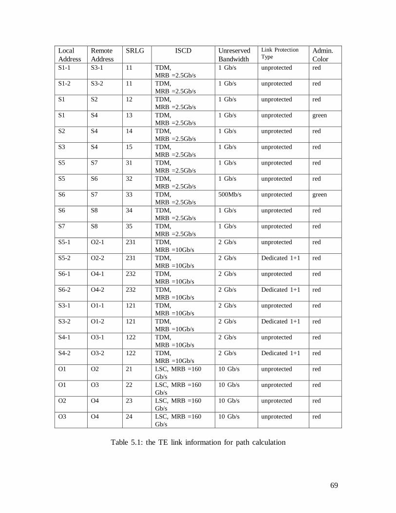
69
Table 5.1: the TE link information for path calculation
LocalAddress
RemoteAddress
SRLG ISCD UnreservedBandwidth
Link ProtectionType
Admin.Color
S1-1 S3-1 11 TDM,MRB =2.5Gb/s
1 Gb/s unprotected red
S1-2 S3-2 11 TDM,MRB =2.5Gb/s
1 Gb/s unprotected red
S1 S2 12 TDM,MRB =2.5Gb/s
1 Gb/s unprotected red
S1 S4 13 TDM,MRB =2.5Gb/s
1 Gb/s unprotected green
S2 S4 14 TDM,MRB =2.5Gb/s
1 Gb/s unprotected red
S3 S4 15 TDM,MRB =2.5Gb/s
1 Gb/s unprotected red
S5 S7 31 TDM,MRB =2.5Gb/s
1 Gb/s unprotected red
S5 S6 32 TDM,MRB =2.5Gb/s
1 Gb/s unprotected red
S6 S7 33 TDM,MRB =2.5Gb/s
500Mb/s unprotected green
S6 S8 34 TDM,MRB =2.5Gb/s
1 Gb/s unprotected red
S7 S8 35 TDM,MRB =2.5Gb/s
1 Gb/s unprotected red
S5-1 O2-1 231 TDM,MRB =10Gb/s
2 Gb/s unprotected red
S5-2 O2-2 231 TDM,MRB =10Gb/s
2 Gb/s Dedicated 1+1 red
S6-1 O4-1 232 TDM,MRB =10Gb/s
2 Gb/s unprotected red
S6-2 O4-2 232 TDM,MRB =10Gb/s
2 Gb/s Dedicated 1+1 red
S3-1 O1-1 121 TDM,MRB =10Gb/s
2 Gb/s unprotected red
S3-2 O1-2 121 TDM,MRB =10Gb/s
2 Gb/s Dedicated 1+1 red
S4-1 O3-1 122 TDM,MRB =10Gb/s
2 Gb/s unprotected red
S4-2 O3-2 122 TDM,MRB =10Gb/s
2 Gb/s Dedicated 1+1 red
O1 O2 21 LSC, MRB =160Gb/s
10 Gb/s unprotected red
O1 O3 22 LSC, MRB =160Gb/s
10 Gb/s unprotected red
O2 O4 23 LSC, MRB =160Gb/s
10 Gb/s unprotected red
O3 O4 24 LSC, MRB =160Gb/s
10 Gb/s unprotected red

70
Because link (S1-2, S3-2) has the same SRLG as the link (S1-1, S3-1), and the latter hasbeen chosen for the primary LSP, it should not be considered when calculating thebackup LSP. The primary and the backup LSPs should be disjoint, so the topology wecan consider for the backup LSP becomes:
Figure 5.3: the topology for the backup LSP
Using the SPF algorithm, we have the “shortest” path (S1, S2, S4, O3, O4, S6, S8, S7)for backup LSP.
Now the Switch 1 can signal both LSPs, e.g., using RSVP-TE. Explicit-routed LSP (ER-LSP) signaling is used. The signaling protocol carrying the ERO establishes the LSPstarting from Switch 1. When signaling arrives at SONET Switch 3, Switch 3 finds outthat it is at the boundary for a hierarchical LSP by the Interface Switching CapabilityDescriptor. Let us assume that there is no existing FA-LSP that meets the requirement ofthe LSP being set up. So Switch 3 establishes a new FA-LSP starting from Switch 3 andterminating on Switch 5. Switch 3 initiates the new FA-LSP. When the signaling arrivesat OXC1, OXC 1 finds out it also needs a new FA-LSP between OXC 1 and 2. Let uscall this FA-LSPF1w, which has Link Protection Type “unprotected”. After that, FA-LSPbetween Switch 3 and 5 is tunneled throughF1w. We call this FA-LSP (between Switch3and Switch5)F2w. It also has Link Protection Type “unprotected”. This FA-LSP tunnelsthe client LSP. Eventually, the client LSP between Switch 1 and Switch 7 is established.It is the primary path we want, which we callPw. A hierarchical LSP establishment isillustrated in Section 2 of this report.
Similarly, for the backup LSP, the FA-LSP between OXC 3 and 4 is calledF1b; the FA-LSP between SONET Switch 4 and 6 is calledF2b. Both of them have Link ProtectionType “unprotected”. And the backup LSP is tunneled through these FA-LSPs, and let uscall it Pb (see Figure 5.4). LSPPw andPb construct the 1:1 LSP protection as desired.
Client Network 1 Optical Network 2 Client Network 3
S1
S2
S3
S4
O1 O2
O3 O4
S5
S6
S7
S8
Optical fiber
OC192 link
OC48 link
0.10.1
0.1
0.1
0.1
0.1
0.05 0.05
0.01 0.01
0.01
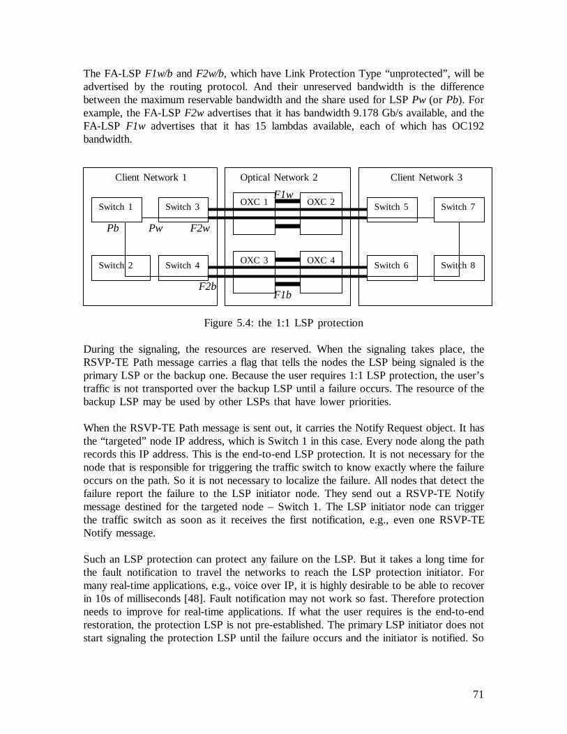
71
The FA-LSPF1w/b andF2w/b, which have Link Protection Type “unprotected”, will beadvertised by the routing protocol. And their unreserved bandwidth is the differencebetween the maximum reservable bandwidth and the share used for LSPPw (or Pb). Forexample, the FA-LSPF2w advertises that it has bandwidth 9.178 Gb/s available, and theFA-LSP F1w advertises that it has 15 lambdas available, each of which has OC192bandwidth.
Figure 5.4: the 1:1 LSP protection
During the signaling, the resources are reserved. When the signaling takes place, theRSVP-TE Path message carries a flag that tells the nodes the LSP being signaled is theprimary LSP or the backup one. Because the user requires 1:1 LSP protection, the user’straffic is not transported over the backup LSP until a failure occurs. The resource of thebackup LSP may be used by other LSPs that have lower priorities.
When the RSVP-TE Path message is sent out, it carries the Notify Request object. It hasthe “targeted” node IP address, which is Switch 1 in this case. Every node along the pathrecords this IP address. This is the end-to-end LSP protection. It is not necessary for thenode that is responsible for triggering the traffic switch to know exactly where the failureoccurs on the path. So it is not necessary to localize the failure. All nodes that detect thefailure report the failure to the LSP initiator node. They send out a RSVP-TE Notifymessage destined for the targeted node – Switch 1. The LSP initiator node can triggerthe traffic switch as soon as it receives the first notification, e.g., even one RSVP-TENotify message.
Such an LSP protection can protect any failure on the LSP. But it takes a long time forthe fault notification to travel the networks to reach the LSP protection initiator. Formany real-time applications, e.g., voice over IP, it is highly desirable to be able to recoverin 10s of milliseconds [48]. Fault notification may not work so fast. Therefore protectionneeds to improve for real-time applications. If what the user requires is the end-to-endrestoration, the protection LSP is not pre-established. The primary LSP initiator does notstart signaling the protection LSP until the failure occurs and the initiator is notified. So
Client Network 1 Optical Network 2 Client Network 3
Switch 1
Switch 2
Switch 3
Switch 4
OXC 1 OXC 2
OXC 3 OXC 4
Switch 5
Switch 6
Switch 7
Switch 8
F1w
F1bF2b
F2wPb Pw

72
end-to-end restoration is even slower and obviously it does not meet the requirement ofreal-time applications.
We will see how another end-to-end protection scheme can improve the recovery time inthe next section.
6.2 Case Study 2: The Domain-specific ProtectionA recent proposal [49] describes a GMPLS LSP protection scheme that is based ondifferent network domains. It is calledsubnetwork protection.
The network across which a hierarchical LSP travels is partitioned into subnetworks. Thenodes constructing the subnetwork have the same multiplexing capacity. Within eachsubnetwork, there is a pre-established backup LSP to protect the primary LSP. And theresource may also be pre-allocated. Because all nodes in a subnetwork have the samemultiplexing capacity, the primary and the backup LSP are at the same level in the LSPhierarchy. The protection mechanism in each subnetwork can be M:N or 1+1. If there is afailure, for M:N protection mechanism, the traffic switchover occurs from the primaryLSP to the backup LSP; for 1+1 protection mechanism, the LSP terminator node selectsthe traffic from the backup LSP. The protection is only performed within the subnetworkwhere the failure occurs. There is no need to do anything in other subnetworks acrosswhich the hierarchical LSP travels. The logical view of this idea is shown by the 1:1protection mechanism in Figure 5.5. There is a protection LSP in the subnetwork for theprimary LSP segment that goes over that subnetwork.
Figure 5.5: The logical view of the subnetwork protection
In Figure 5.5, the primary LSP is (Node 1, Node 3, Node 5, Node 7, Node 9, Node 11).If the link between Node 5 and Node 7 is broken, the protection LSP (Node 5, Node 6,
Network 1 Network 2 Network 3
Node 1
Node 2
Node 3
Node 4
Node 7
Node 8
Node 5
Node 6
Node 9
Node 10
Node 11
Node 12
Primary LSP
Backup LSP
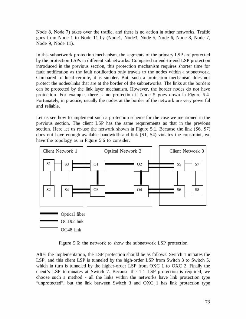
73
Node 8, Node 7) takes over the traffic, and there is no action in other networks. Trafficgoes from Node 1 to Node 11 by (Node1, Node3, Node 5, Node 6, Node 8, Node 7,Node 9, Node 11).
In this subnetwork protection mechanism, the segments of the primary LSP are protectedby the protection LSPs in different subnetworks. Compared to end-to-end LSP protectionintroduced in the previous section, this protection mechanism requires shorter time forfault notification as the fault notification only travels to the nodes within a subnetwork.Compared to local reroute, it is simpler. But, such a protection mechanism does notprotect the nodes/links that are at the border of the subnetworks. The links at the borderscan be protected by the link layer mechanism. However, the border nodes do not haveprotection. For example, there is no protection if Node 5 goes down in Figure 5.4.Fortunately, in practice, usually the nodes at the border of the network are very powerfuland reliable.
Let us see how to implement such a protection scheme for the case we mentioned in theprevious section. The client LSP has the same requirements as that in the previoussection. Here let us re-use the network shown in Figure 5.1. Because the link (S6, S7)does not have enough available bandwidth and link (S1, S4) violates the constraint, wehave the topology as in Figure 5.6 to consider.
Figure 5.6: the network to show the subnetwork LSP protection
After the implementation, the LSP protection should be as follows. Switch 1 initiates theLSP, and this client LSP is tunneled by the high-order LSP from Switch 3 to Switch 5,which in turn is tunneled by the higher-order LSP from OXC 1 to OXC 2. Finally theclient’s LSP terminates at Switch 7. Because the 1:1 LSP protection is required, wechoose such a method - all the links within the networks have link protection type“unprotected”, but the link between Switch 3 and OXC 1 has link protection type
Optical fiber
OC192 link
OC48 link
Client Network 1 Optical Network 2 Client Network 3
S1
S2
S3
S4
O1 O2
O3 O4
S5
S6
S7
S8
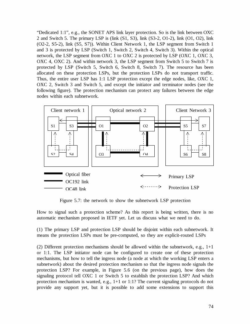
74
“Dedicated 1:1”, e.g., the SONET APS link layer protection. So is the link between OXC2 and Switch 5. The primary LSP is (link (S1, S3), link (S3-2, O1-2), link (O1, O2), link(O2-2, S5-2), link (S5, S7)). Within Client Network 1, the LSP segment from Switch 1and 3 is protected by LSP (Switch 1, Switch 2, Switch 4, Switch 3). Within the opticalnetwork, the LSP segment from OXC 1 to OXC 2 is protected by LSP (OXC 1, OXC 3,OXC 4, OXC 2). And within network 3, the LSP segment from Switch 5 to Switch 7 isprotected by LSP (Switch 5, Switch 6, Switch 8, Switch 7). The resource has beenallocated on these protection LSPs, but the protection LSPs do not transport traffic.Thus, the entire user LSP has 1:1 LSP protection except the edge nodes, like, OXC 1,OXC 2, Switch 3 and Switch 5, and except the initiator and terminator nodes (see thefollowing figure). The protection mechanism can protect any failures between the edgenodes within each subnetwork.
Figure 5.7: the network to show the subnetwork LSP protection
How to signal such a protection scheme? As this report is being written, there is noautomatic mechanism proposed in IETF yet. Let us discuss what we need to do.
(1) The primary LSP and protection LSP should be disjoint within each subnetwork. Itmeans the protection LSPs must be pre-computed, so they are explicit-routed LSPs
(2) Different protection mechanisms should be allowed within the subnetwork, e.g., 1+1or 1:1. The LSP initiator node can be configured to create one of these protectionmechanisms, but how to tell the ingress node (a node at which the working LSP enters asubnetwork) about the desired protection mechanism so that the ingress node signals theprotection LSP? For example, in Figure 5.6 (on the previous page), how does thesignaling protocol tell OXC 1 or Switch 5 to establish the protection LSP? And whichprotection mechanism is wanted, e.g., 1+1 or 1:1? The current signaling protocols do notprovide any support yet, but it is possible to add some extensions to support this
Client network 1 Optical network 2 Client Network 3
S1
S2
S3
S4
O1 O2
O3 O4
S5
S6
S7
S8
Optical fiber
OC192 link
OC48 link
Primary LSP
Protection LSP

75
subnetwork protectionscheme, e.g., a new object in RSVP-TE. This new object is onlyprocessed by the nodes of the primary LSP that are at the border of differentsubnetworks. For example, Switch 1, Switch 3, OXC 1, OXC 2, Switch 5, Switch 7 inFigure 5.6 (see the previous page).
(3) The protection LSP should be pre-established so as to provide fast recovery.Resources may be pre-allocated as well. For M:N protection, lower priority traffic shouldbe allowed to use the resource if the protection LSP is not protecting.
(4) Coordination mechanisms should be used to avoid the multi-layer protectioncontention if there is any. For example, “unprotected” link protection type may be used tosignal both of the primary and backup LSPs.
(5) There is a problem concerning the incoming interface. Within each subnetwork, theprimary LSP segment and the backup LSP merge at the edge node. The incominginterface may be regarded as a “label” and involved in label switching, e.g., in a networkconstructed by nodes that is fiber-switch capable, the incoming port may determine theoutgoing port. Another example is an MPLS router that is packet-switch capable usesinterface-based label space. The problem isillustrated in the following figure.
Figure 5.8: the incoming interface problem in the subnetwork protection
Node 1 switches the traffic from interface A to interface B if a failure between itself andNode 4 occurs. Then the traffic arrives at Node 4 through interface D, instead of C. Ifthe label is unique node-widely (per-node label space), then there is no problem for Node4 to work as usual, and the discussion can be stopped here. But in many situations, thisis not the case. In order to reuse the label, usually per-interface label space is used. Forexample, a fiber can transport multiple wavelengths (lambdas), and another fiber on adifferent port can transport all the same wavelengths (lambdas). Let us assume that Node4 has such an entry (see Figure 5.9) in its label forwarding table in the example shown inFigure 5.8:
Backup LSP
Primary LSP
Network
Node 1
Node 2
Node 4
Node 3
A
B D
C E

76
Figure 5.9: the label forwarding entry in the example
Now the incoming interface has changed for Node 4, and how to tell it to accept thetraffic from another interface and continue the label forwarding? One solution is to signalNode 4 to change the incoming interface C to D in its label forwarding entry after thefailure is detected. It takes time and this protection would lose much of its value. Anothersolution is to tell Node 4 about it when the protection LSP is being established. In orderto support this solution, a selector may be implemented in Node 4 that can select trafficfrom one of the multiple ports. Node 4 monitors the traffic from interface C and D, andit selects the healthier traffic from one of the two. The incoming interface may beprogrammed in the label forwarding entry before label switching occurs for optimization(see Figure 5.10) if the protection type allows. Or Node 4 can change the incominginterface in its label forwarding entry just before it is going to select the traffic fromanother interface.
Figure 5.10: the interfaces for primary and backup LSPs are pre-programmed
(6) How to set up the multi-layer protection scheme like the link layer protection betweennodes S3 and O1, O2 and S5? It is done usually by configuration. So is the set-up ofcoordination mechanism to avoid the multi-layer protection contention.
The other way to establish the entiresubnetwork protectionis by configuration. Forexample, on the network manager, the network administrator can configure such an LSPprotection scheme. At the beginning, the network administrator requires the pathcomputation component in the primary LSP initiator node to calculate the primary LSP.Then the LSP protection type and the primary LSP information (e.g., the nodes traveled
Incoming information Outgoing information
Incoming label Outgoing label
Outgoing interface E
…
Incoming interface C
Incoming information Outgoing information
Incoming label Outgoing label
Outgoing interface E
…
Incoming interface C
Incoming interface D

77
by the primary LSP) are sent to the ingress node of the primary LSP segment within eachsubnetwork, for example, node O1 in the optical network in Figure 5.6. At each ingressnode, the protection LSP is calculated to protect the LSP segment that travels within thatsubnetwork. Note that the protection LSP must be disjoint with the primary LSP segmentand the protection type should be honored. After that, the link layer protection (if needed)and the coordination for avoiding multi-layer protection contention can be done byconfiguration. How to solve the incoming interface problem? The egress node mayprovide an interface to network management for query and configuration. Such aninterface allows the network administrator to manually query and configure the labelforwarding table. We can see that using configuration to create such a protection schemeis tedious and error-prone.
Summary of the Subnetwork Protection SchemeIf the link between subnetworks fails, then the link layer protection is triggered. And it isexpected that the link layer protection takes a short time to recover, e.g., the SONETAPS just takes less than 50 ms to recover. If there is a failure (not the edge nodes) in asubnetwork, fault notification just needs to notify the head node of the LSP segmentwithin that network. So the notification message travels only within that subnetwork.Compared to end-to-end LSP protection, it takes less time. The paper [50] proves that, intheory, it is possible to guarantee the 50 ms recovery time in large mesh networks byproperly partitioning the network and applying subnetwork protection.
This subnetwork protection scheme also has another advance – it can protect a number ofLSPs (see Figure 5.11). If a failure between Node 1 and Node 4 occurs, the protectionLSP, which has the same level as the primary LSP segment within the subnetwork, isactivated to protect the primary LSP. The tunneled low-order LSPs, e.g., LSP 1, 2 and 3in the example, are not affected, and they are not even aware of the failure.
Figure 5.11: the subnetwork protection idea protects multiple low-order LSPs
Backup high-order LSPPrimary high-order LSP
Low-order LSP
Network 2
Node 1
Node 2
Node 4
Node 3
Node 5
LSP 1
LSP 2
LSP 3
Network 1
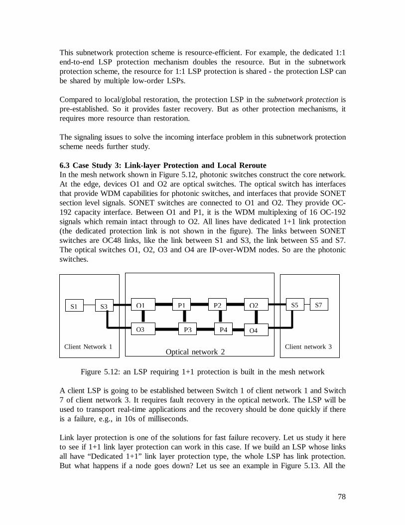
78
This subnetwork protection scheme is resource-efficient. For example, the dedicated 1:1end-to-end LSP protection mechanism doubles the resource. But in the subnetworkprotection scheme, the resource for 1:1 LSP protection is shared - the protection LSP canbe shared by multiple low-order LSPs.
Compared to local/global restoration, the protection LSP in thesubnetwork protectionispre-established. So it provides faster recovery. But as other protection mechanisms, itrequires more resource than restoration.
The signaling issues to solve the incoming interface problem in this subnetwork protectionscheme needs further study.
6.3 Case Study 3: Link-layer Protection and Local RerouteIn the mesh network shown in Figure 5.12, photonic switches construct the core network.At the edge, devices O1 and O2 are optical switches. The optical switch has interfacesthat provide WDM capabilities for photonic switches, and interfaces that provide SONETsection level signals. SONET switches are connected to O1 and O2. They provide OC-192 capacity interface. Between O1 and P1, it is the WDM multiplexing of 16 OC-192signals which remain intact through to O2. All lines have dedicated 1+1 link protection(the dedicated protection link is not shown in the figure). The links between SONETswitches are OC48 links, like the link between S1 and S3, the link between S5 and S7.The optical switches O1, O2, O3 and O4 are IP-over-WDM nodes. So are the photonicswitches.
Figure 5.12: an LSP requiring 1+1 protection is built in the mesh network
A client LSP is going to be established between Switch 1 of client network 1 and Switch7 of client network 3. It requires fault recovery in the optical network. The LSP will beused to transport real-time applications and the recovery should be done quickly if thereis a failure, e.g., in 10s of milliseconds.
Link layer protection is one of the solutions for fast failure recovery. Let us study it hereto see if 1+1 link layer protection can work in this case. If we build an LSP whose linksall have “Dedicated 1+1” link layer protection type, the whole LSP has link protection.But what happens if a node goes down? Let us see an example in Figure 5.13. All the
P1 P2
P3 P4
O2O1S1 S3 S5 S7
O3 O4
Client network 3Optical network 2
Client Network 1

79
nodes are IP-over-WDM nodes. If node N3 goes down, how to recover the failure evenif all the links have 1+1 link protection? So just link layer protection cannot work. Otherrecovery mechanisms are needed to complement the link protection.
Figure 5.13: all links have 1+1 link protection between nodes
Because an LSP which has 1+1 link protection has doubled the resource for the traffic,further expensive recovery mechanisms are not desired any more. One of the solutions isto use local reroute. Let us consider if this recovery mechanism can work.
When establishing the primary LSP, the RSVP-TE Path message carries the RSVP-TEprotection object, which signals “Dedicated 1+1”. To avoid multiple layer protectioncontention, the coordination mechanism must be set during the signaling. Let us use hold-off timer. Note that, in order to meet the recovery time requirement, the hold-off timeset-up must consider the time needed for MPLS-based recovery in case the link layerprotection fails. We use LSP local reroute as the MPLS-based recovery in this case. Andthe link layer protection has higher priority than the MPLS-based recovery. Let us assumethat the primary LSP is (S1, S3, O1, P1, P2, O2, S5, S7). The primary LSP contains:FA-LSP1, which is from O1 to O2; and FA-LSP2, which is from S3 to S5. Whenestablishing FA-LSP1, P2 knows that it is the penultimate node of this FA-LSP, e.g.,routing tells P2 that it is directly connected to O2. Let us assume we have such anadministration policy that the penultimate node of the FA-LSP must notify the initiatornode of the FA-LSP. The “target” address for the Notify message can be configured. Inthis case, P2 can send out the RSVP-TE Notify message targeted to O1. O2 is thepenultimate node of FA-LSP2, and similarly it knows it will send a Notify message to S3if S5 fails.
At first, we consider Case 1 (see the section about local restoration for what the differentcases are), for example, P2 goes down. P1 detects its neighbor’s failure, e.g., by theHello protocol (the Hello is exchanged between the neighbors every 5 ms). The link layerprotection is triggered. Unfortunately, after the hold-off time, P1 finds out the failure isstill there. So the hold-off timer triggers the LSP local restoration. The routinginformation database (LSDB) in P1 still shows that there is a route (P1, P3, P4, O2) toO2. Without waiting for routing information synchronization, P1 constructs an ER-LSP toreach O2, whose RSVP-TE ERO object contains P1, P3, P4 and O2. Because all ofinterfaces connecting these nodes have the same interface switching type – LambdaSwitch Capable, there is no higher-order LSP needed. The reroute ER-LSP (P1, P3, P4,O2) has the same level as FA-LSP1 (O1, P1, P2, O2). When the signaling RSVP-TE
N2 N3 N4N1
Figure 5.12: the primary LSP
P1 P2 O2O1S1 S3 S5 S7

80
Path message driven by the ERO object arrives at O2, based on the PSVP-TE Sessionobject and Sender template object, O2 understands the LSP has to be modified. So O2modifies its label forwarding table and responds with a RSVP-TE Resv message. Themessage arrives at P1. And P1 understands that the reroute succeeds. So it also modifiesits label forwarding table and switches over the traffic onto the reroute ER-LSP. If nodeP1 goes down, the reroute process is similar as both P1 and P2 are transit nodes of FA-LSP1.
If O2 fails, then reroute Case 2 occurs. P2 detects its neighbor’s failure. As P2 isconfigured to notify the FA-LSP1 initiator O1, it sends out the RSVP-TE Notify messagedestined to O1. O1 is notified, and it tells all the tunneled low-order LSPs to reroute as itis the border of the hierarchical LSP. For example, it tells node S3 of FA-LSP2 toreroute. S3 consults its current routing database and builds the ERO object to signal areroute ER-LSP. It understands it must cross the optical network to reach SONET switchS5. So the ERO object (S3, O3, P3, P4, O4, S5) is built and part of this ER-LSP (O3,P3, P4, O4) is a higher order LSP compared to FA-LSP2. The ERO drives the signaling.When it arrives at node O3, the higher-order FA-LSP is triggered to set up – let us callit FA-LSP1’. After that the reroute ER-LSP reaches S5. And the FA-LSP2 is tunneled bythis FA-LSP1’. The reroute bypasses the faulty O2.
If O1 fails, the reroute Case 3 occurs. S3 detects its neighbor’s failure and S3 triggers thereroute. S3 consults its current routing database and builds the ERO object to signal areroute ER-LSP. The process is like what the S3 does in reroute Case 2 (see thepreceding paragraph).
When we use reroute as the recovery method, we need to carefully consider the networktopology. Due to the network topology, reroute may not work. For example, in the casewe just described, if the user wants the fault recovery from end to end, reroute cannotwork if node S5 goes down.

81
7. ConclusionWe have talked about the objectives for the LSP protection/restoration in Section 3. Wenote that the objective tobe cost-effectivemay involve non-technical factors, but we donot discuss them here in this report. We compare the LSP protection/restorationmechanisms in GMPLS networks in the following table.
LSPrecoverymechanisms
Resourcerequirements
Speed of recovery Complexity Applicationscope
Conventionallocalrestoration
No resource ispre-allocated,the repairedLSP requiressame resource
Very slow as itwaits for theroutingsynchronization
No change tothe currentsignalingprotocols
Limited as theuser’s strictER-LSP isnot desired tobe rerouted.
Localrestorationwith ER-LSP [47]
No resource ispre-allocated,the repairedLSP requiressame resource
Fast. It does not waitfor the routingsynchronization tosignal the reroutepath. The pathcomputation takeslittle time.
No change tothe currentsignalingprotocol, but itrequires extraintelligence
Limited as theuser’s strictER-LSP isnot desired tobe rerouted.
End-to-endrestoration
No resource ispre-allocated,the repairedLSP requiressame resource
Very slow. Faultlocalization isperformed, faultnotification takestime to travel acrossnetworks, and thereroute LSP is notset up until thefailure occurs.
No change tothe currentsignalingprotocol
Can be usedin anysituations andthe recoverymeets trafficengineeringgoals
Localprotection
Doubleresource is pre-allocated
Very fast as it isdone at thelink/physical layer
Additionalconfiguration isneeded to setup
It cannoteasily providenodeprotection.
End-to-endprotection
Additionalresource is pre-allocated,dedicated 1+1LSP protectionrequires doubleresource
1+1 LSPprotection does notneed faultnotification butM:N LSPprotection does.
Additionalconfigurationmay be neededto set up theprotection onthe end nodesof the LSP
It can beused in anysituations
Table 6.1: comparison of recovery mechanismsAll protection/restoration mechanisms sacrifice resource to achieve fast recovery. Becauseadditional resource is pre-allocated in the protection mechanism, the protection mechanismis expected to provide faster recovery than restoration. So objectives for LSP recovery

82
(1) to optimize the use of resourcesand (2) to provide fast recovery and minimize thedisruption to data traffic of any failureare conflicting. Many protection/restorationmechanisms require signaling at the time of failure. The more signaling is required, themore time the mechanism takes to recover, and the less likely the recovery is timely.
We can achieve fastest recovery if we pay double resource, e.g., using the link/physicallayer protection. The 1+1 LSP protection requires double resource, which is the mostexpensive LSP protection, and it can provide fastest LSP recovery. Any other protectionmechanisms that share backup resource require fault notification. For example, the M:N,1:N or 1:1 end-to-end LSP protection requires that fault notification travels across anumber of nodes, which may cost time. The subnetwork protection mechanism tries toshorten the fault notification time but the nodes at the network boundary do not have anyprotection.
Many restoration mechanisms require a lot of signaling, so they usually do not meet real-time applications’ requirement. The local restoration using ER-LSP proposed by [47] doesnot need fault notification and it does not need to wait for routing informationsynchronization. Although it needs to compute the ER-LSP to reroute, it does not give aburden to today’s CPU. So it may be a fast restoration solution. However, the applicationscope of local restoration is limited.
Restoration mechanisms allocate resources after failure occurrence so they are resourceeffective but it takes time for them to provide recovery. Protection mechanisms providefast recovery but they require additional resources. We should carefully consider thetrade-off to choose the appropriate recovery mechanism so as to meet the requirements ofusers and network administration.
Compared to lower layer recovery mechanisms, the recovery mechanisms at the GMPLSlevel are relatively slow and may require more resources. Lower layer recoverymechanisms can provide fast recovery. But they have their limitations and disadvantages.For example, WDM networks may require complicated implementation and configurationfor protection/restoration. And link layer protection cannot easily provide node protection.
In practice, usually a single type of protection mechanism does not satisfy the complicatedworking environment or user requirements. So a combination of recovery mechanisms isoften the solution. When we choose a recovery solution, we need to achieve the balancebetween required resources and recovery time and the balance between cost and highsurvivability.
Nowadays, a lot of proposals have come up for LSP protection/restoration. GMPLSextends MPLS, but the LSP protection/restoration mechanisms that work in MPLSnetworks may not always work in GMPLS networks. For example, the "detour" proposal[48] makes the LSP very fault-tolerant in MPLS networks, but the current methoddescribed is only suitable for unidirectional LSPs. That is not applicable for GMPLS asbidirectional LSPs are recommended in GMPLS. Furthermore, the proposal places strict

83
constraints to the GMPLS network nodes when the "detour" LSP for protection is set up(see [51]). It is likely that the proposals that only work in MPLS networks but not inGMPLS networks would be dropped by IETF, e.g., [53] has been dropped, because of itslimited scope.
Some proposals for LSP protection/restoration require the current signaling protocol tohave more extensions, e.g., the one described in [48]. IETF considers these proposalsvery carefully as they would have a side-effect or put too much burden on the protocol.Some of these proposals are dropped, e.g., [54]. Therefore some researchers suggest thatrecovery mechanisms should be split from signaling protocol extensions (see [52]).
For local reroute, the aid from the signaling protocol is inevitable. But for the time being,none of the proposals in this area gets majority support. The issue is still being discussedin IETF.
With the further development of GMPLS, it is expected that more and more solutions arecoming up for LSP protection/restoration in GMPLS.
84
References:[1] E. Rosen, A. Viswananthan, et al.,Multiprotocol Label Switching Architecture,RFC3031, IETF, http://www.ietf.org.
[2] E. Mannie, et al.,Generalized Multi-Protocol Label Switching(GMPLS)Architecture, draft-ietf-ccamp-gmpls-architecture-02.txt, work in progress, IETF,http://www.ietf.org.
[3] P. Newman, G. Minshall, T. Lyon and L. Huston,IP switching and gigabitrouters, IEEE communication magazines, January, 1997, pp.64-69.
[4] P. Newman et al.,Ipsilon's General Switch Management Protocol Specification,RFC1987, IETF, http://www.ietf.org.
[5] P. Newman, W. L. Edwards, et al.,Transmission of Flow Labelled IPv4 on ATMData Links, RFC1954, IETF, http://www.ietf.org.
[6] Y. Rekhter, B. Davie, et al.,Cisco Systems' Tag Switching Architecture Overview,RFC2105, IETF, 1997.
[7] C. Metz, An overview of IP Switching Technology, IBM Corporation,http://www.networking.ibm.com/isr/ip/ipswp1.htm.
[8] Professor R. Jain, Department of Computer and Information Science, The OhioState University, http://www.cis.ohio-state.edu/~jain/cis788-97/ip_switching.
[9] D. Awduche, Y. Rekhter, J. Drake, R. Coltun,Multi-Protocol Lambda Switching:Combining MPLS Traffic Engineering Control With Optical Crossconnects, draft-awduche-mpls-te-optical-03.txt, Work in Progress, April, 2001, IETF,http://www.ietf.org.
[10] P. Ashwood-Smith et. al,Generalized MPLS - Signaling FunctionalDescription, draft-ietf-mpls-generalized-signaling-02.txt, IETF Draft, Work in Progress,March, 2001, IETF, http://www.ietf.org.
[11] E. Mannie et al., Section 3.2 of GMPLS Architecture,draft-ietf-ccamp-gmpls-architecture-02.txt, work in progress, IETF, http://www.ietf.org.
[12] A. Banerjee, J. Drake, et al.,Generalized Multiprotocol Label Switching: AnOverview of Signaling Enhancements and Recovery Techniques.July 2001, IEEECommunication Magazine.
[13] B. Rajagopalan, et al., Abstract ofIP over Optical Networks: A Framework,draft-ietf-ipo-framework-01.txt, work in progress, IETF draft, http://www.ietf.org.

85
[14] B. Rajagopalan, et al.,IP over Optical Networks: A Framework, draft-ietf-ipo-framework-01.txt, IETF draft, http://www.ietf.org.
[15] B. Rajagopalan, J. Luciani, et al., Section 3 of draft-many-ip-optical-framework-03.txt, work in progress, IETF.
[16] D. Awduche, J. Malcolm, et al., Section 2 ofRequirements for TrafficEngineering Over MPLS(RFC2702), IETF, http://www.ietf.org.
[17] P. Srisuresh, P. Joseph,TE LSAs to extend OSPF for Traffic Engineering, draft-srisuresh-ospf-te-02.txt, work in progress, IETF, http://www.ietf.org.
[18] D. Cheng,OSPF Extensions to Support Multi-Area Traffic Engineering,draft-cheng-ccamp-ospf-multiarea-te-extensions-00.txt, work in progress, IETF,http://www.ietf.org.
[19] K. Kompella, Y. Rekhter, et al.,Routing Extensions in Support of GeneralizedMPLS, draft-ietf-ccamp-gmpls-routing-04.txt, work in progress, IETF,http://www.ietf.org.
[20] K. Kompella, Y. Rekhter,LSP hierarchy with Generalized MPLS TE, draft-ietf-mpls-lsp-hierachy-06.txt, work in progress, IETF, http://www.ietf.org.
[21] K. Kompella, Y. Rekhter, A. Banerjee, et al.,OSPF Extensions in Support ofGeneralized MPLS, draft-ietf-ccamp-ospf-gmpls-extensions-07.txt, work in progress,IETF, http://www.ietf.org.
[22] K. Kompella, Y. Rekhter, A. Banerjee, et al.,IS-IS Extensions in Support ofGeneralized MPLS, draft-ietf-isis-gmpls-extensions-13.txt, work in progress, IETF,http://www.ietf.org.
[23] B. Rajagopalan, J. Luciani, D. Awduche, et al., Section 8.2 ofIP over OpticalNetworks: A Framework, draft-ietf-ipo-framework-01.txt, work in progress, IETF,http://www.ietf.org.
[24] K. Kompella, Y. Rekhter, A. Banerjee, J. Drake, et al.,Routing Extensions inSupport of Generalized MPLS, draft-ietf-ccamp-gmpls-routing-04.txt, working inprogress, IETF, http://www.ietf.org.
[25] P. Ashwood-Smith, L. Berger, et al.,Generalized MPLS Signaling - CR-LDPExtensions, draft-ietf-mpls-generalized-cr-ldp-06.txt, work in progress, IETF,http://www.ietf.org.
86
[26] L. Berger, P. Ashwood-Smith, A. Banerjee, et al.,Generalized MPLS Signaling -RSVP-TE Extensions, draft-ietf-mpls-generalized-rsvp-te-07.txt, work in progress,IETF, http://www.ietf.org.
[27] L. Berger, P. Ashwood-Smith, A. Banerjee, G. Bernstein, et al.,GeneralizedMPLS - Signaling Functional Description,draft-ietf-mpls-generalized-signaling-08.txt,work in progress, IETF, http://www.ietf.org.
[28] L. Berger, P. Ashwood-Smith, A. Banerjee, G. Bernstein, et al., Section 4 ofGeneralized MPLS - Signaling Functional Description, draft-ietf-mpls-generalized-signaling-08.txt, work in progress, IETF, http://www.ietf.org.
[29] B. Davie, Y. Rekhter, Section 2 ofMPLS Technology and Applications, MorganKaufmann Publishers, 2000, ISBN 1558606564.
[30] Y. Suemura, A. Kolarov, T. Shiragaki,Protection of Hierarchical LSPs, draft-suemura-protection-hierarchy-00.txt, work in progress, IETF, http://www.ietf.org.
[31] V. Sharma, F. Hellstrand, et al.,Framework for MPLS-based Recovery, Section2, draft-ietf-mpls-recovery-frmwrk-04.txt, work in progress, IETF, http://www.ietf.org
[32] B. Doshi, S. Dravida, P.Harshavardhana, O. Hauser, Y. Wang,Optical NetworkDesign and Restoration, Bell Labs Technical Journal, Jan-March, 1999, seehttp://www.lucent.com/minds/techjournal/pdf/jan-mar1999/paper04.pdf
[33] G. Maier, S. De Patre, M. Martinelli, et al.,Resilience schemes in WDMnetworks, Italy, June 2001, see http://leos.unipv.it/Pattavina.pdf
[34] V. Sharma, F. Hellstrand, et al.,Framework for MPLS-based Recovery, Section1.2, draft-ietf-mpls-recovery-frmwrk-04.txt, work in progress, IETF,http://www.ietf.org
[35] W. S. Lai, D. McDysan, et al., Section 5.5,Network Hierarchy and MultilayerSurvivability, draft-ietf-tewg-restore-hierarchy-00.txt, work in progress, IETF,http://www.ietf.org.
[36] V. Sharma, B. Crane, et al.,Framework for MPLS-based Recovery, draft-ietf-mpls-recovery-frmwrk-03.txt, work in progress, IETF, http://www.ietf.org.
[37] D. Katz, D. Yeung, et al.,Traffic Engineering Extensions to OSPF, draft-katz-yeung-ospf-traffic-06.txt, work in progress, IETF, http://www.ietf.org.
[38] J. Lang, et al.,Link Management Protocol, draft-ietf-ccamp-lmp-04.txt, work inprogress, IETF, http://www.ietf.org.
87
[39] L. Berger, P. Ashwood-Smith, A. Banerjee, et al.,Generalized MPLS Signaling -RSVP-TE Extensions, draft-ietf-mpls-generalized-rsvp-te-07, work in progress, IETF,http://www.ietf.org.
[40] L. Zhang, et al., Resource ReSerVation Protocol (RFC2205), IETF,http://www.ietf.org.
[41] L. Andersson, P. Doolan, et al.,LDP Specification(RFC3036), IETF,http://www.ietf.org.
[42] B. Jamoussi, L. Andersson, et al.,Constraint-Based LSP Setup using LDP(RFC3212), IETF, http://www.ietf.org.
[43] P. Ashwood-Smith, L. Berger, et al.,Generalized MPLS Signaling - CR-LDPExtensions, draft-ietf-mpls-generalized-cr-ldp-06.txt, working in progress, IETF,http://www.ietf.org.
[44] A. Banerjee, J. Drake, et al., Section “GMPLS Protection and RestorationTechniques” ofGeneralized Multiprotocol Label Switching: An Overview of SignalingEnhancements and Recovery Techniques.July 2001, IEEE Communication Magazine.
[45] V. Sharma, F. Hellstrand, et al.,Framework for MPLS-based Recovery, Section3.4, draft-ietf-mpls-recovery-frmwrk-04.txt, work in progress, IETF draft, 5, 2002.
[46] Jeff Doyle, Routing TCP/IP, Volume 1, Cisco Press, 1998, ISBN 1578700418.
[47] B. Davie, Y. Rekhter, Section 7 ofMPLS Technology and Applications, MorganKaufmann Publishers, 2000, ISBN 1558606564.
[48] Ping Pan, Der-Hwa Gan, et al.,Fast Reroute Extensions to RSVP-TE for LSPTunnels, draft-ietf-mpls-rsvp-lsp-fastreroute-00.txt, work in progress, July 2002, IETF,http://www.ietf.org.
[49] Y. Suemura, A. Kolarov, T. Shiragaki,Protection of Hierarchical LSPs, draft-suemura-protection-hierarchy-00.txt, work in progress, IETF, http://www.ietf.org.
[50] C. Ou, H. Zang, B. Mukherjee,Sub-Path Protection for Scalability and FastRecovery in WDM Mesh Networks, Dept. of Computer Science, Univ. of California,Davis, CA, 2001.
[51] B. Miller, E. Harrison, A. Farrel,An examination of the methods for protectingMPLS LSPs against failures of network resources, Data Connection, Oct 2001,http://www.dataconnection.com/.

88
[52] D. Papadimitriou, et al.,Restoration Mechanisms and Signaling in OpticalNetworks, Proceedings of the Fiftieth Internet Engineering Task Force, March 18-23,2001, http://www.ietf.org/proceedings/01mar/slides/ccamp-7/.
[53] C. Huang, V. Sharma, S. Makam and K. Owens,A Path Protection/RestorationMechanism for MPLS Networks, draft-chang-mpls-path-protection-01.txt, work inprogress, July, 2000, http://www.ietf.org.
[54] C. Huang, V. Sharma, S. Makam and K. Owens,Extensions to RSVP-TE forMPLS Protection, IETF, work in progress, IETF draft, June, 2000,http://www.ietf.org.