the lustering of tbg2 - digital.library.unt.edu/67531/metadc711107/m2/1/high... · removal of air...
TRANSCRIPT
5 - 25- 9s-
SAND94-1832*UC-237 Unlimited Release Printed May 1995
The Lustering of TBG2 R. B. Diver, S. Jones, S. Robb, and A. R. Mahoney
Prepared by Sandia National Laboratories Albuquerque, New Mexico 87185 for the United States Department of Energy under Contract DE-AC04-94AL85000

Issued by Sandia National Laboratories, operated for the United States Department of Energy by Sandia Corporation. NOTICE This report was prepared as an account of work sponsored by an agency of the United States Government. Neither the United States Govern- ment nor any agency thereof, nor any of their employees, nor any of their contractors, subcontractors, or their employees, makes any warranty, express or implied, or assumes any legal liability or responsibility for the accuracy, completeness, or usefulness of any information, apparatus, product, or process disclosed, or represents that its use would not infringe privately owned rights. Reference herein to any specific commercial product, process, or service by trade name, trademark, manufacturer, or otherwise, does not necessarily constitute or imply its endorsement, recommendation, or favoring by the United States Government, any agency thereof or any of their contractors or subcontractors. The views and opinions expressed herein do not necessarily state or reflect those of the United States Government, any agency thereof or any of their contractors.
Printed in the United States of America. This report has been reproduced directly from the best available copy.
Available to DOE and DOE contractors from Office of Scientific and Technical Information PO Box 62 Oak Ridge, T N 37831 Prices available from (615) 576-8401, FTS 626-8401
Available to the public from National Technical Information Service US Department of Commerce 5285 Port Royal Rd Springfield, VA 22161 NTIS price codes Printed copy: A03 Microfiche copy: A01

DISCLAIMER.
Portions of this document may be illegible in electronic image products. Images are produced from the best available original document.
I

SAND94-1832 Unlimited Release Printed May 1995
Distribution Category UC-237
THE LUSTERING OF TBC-2
Richard B. Diver, Scott Jones, Stacy Robb, and A. Rod Mahoney Sandia National Laboratories
Albuquerque, New Mexico 87185
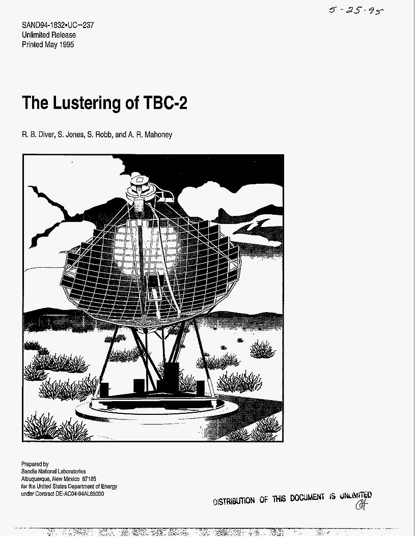
Abstract Two test bed concentrators (TBCs) were designed to provide high-performance test beds for advanced solar receivers and converters. However, the second-surface silvered-glass mirror facets on the TBCs, which were originally manufactured by the Jet Propulsion Laboratory, have experienced severe silver corrosion. To restore reflectance, TBC- 2 was refurbished with a lustering technique developed at Sandia National Laboratories. In the lustering technique, second-surface silvered thin-glass mirrors were applied over the corroded facets, thereby increasing the dish reflectivity and raising the available power of TBC-2 from approximately 70 to 78 kW,. Degradation of the original optical accuracy of the TBC facets was determined to be minimal.
Lustering was chosen over facet replacement because of the lower cost, the anticipated improvement in corrosion resistance, and the shorter project duration. This report includes background information, details of the lustering process, and test results from TBC-2 characterization, both before and after lustering.

i i

Table of Contents Glossary ...................................................................................................................................................................... iv Introduction .................................................................................................................................................................. 1
Background ..................................................................................................................................................... 2 Design Approach ............................................................................................................................................ 3
Lustering Process .......................................................................................................................................................... 7 Bonding .......................................................................................................................................................... 8 Preparing ........................................................................................................................................................ 9 Laminating ................................................................................................................................................... 11
Performance Characterization Results ......................................................................................................................... 13 Summary and Conclusions .......................................................................................................................................... 17 References .................................................................................................................................................................. 18
1 . 2 . 3 . 4 . 5 . 6 . 7 . 8 . 9 . 10 . 11 . 12 . 13 . 14 . 15 . 16 .
17 .
18 .
19 .
20 .
List of Figures
Photograph of the lustered TBC-2 ................................................................................................................... 1 Typical corrosion of a TBC mirror .................................................................................................................. 2 Photograph of a lustered TBC facet after environmental exposure ................................................................... 6 CIRCE2-predicted effect of radius-of-curvature on peak flux and intercept ...................................................... 6 Photograph of the Engine Test Facility high-bay during the lustering process ................................................. 7 Photograph of TBC-2 midway through the lustering process ........................................................................... 7 Preparation for mirror bonding ........................................................................................................................ 8 Tacking adhesive during the bonding process .................................................................................................. 8 Bonding the adhesive ...................................................................................................................................... 9 Removal of air bubbles trapped under the adhesive .......................................................................................... 9 Removal of the posts used for the mirror covers ............................................................................................. 10
Filling in the broken corner of a TBC facet ................................................................................................... 10 Broken mirror corner .................................................................................................................................... 10
Irreparably damaged TBC facet ..................................................................................................................... 10 Illustration ofthe laminating process ............................................................................................................. 12 Representative BCS flux distributions of TBC-2 near the focal plane before (left) and after (right) lustering ..................................................................................................................................... 14 Representative BCS flux distributions of TBC-2 at 8 cm (3.15 in.) behind the focal plane before (left) and after (right) lustering ........................................................................................................... 14 Representative BCS flux distributions of TBC-2 at 15.7 m (6.18 in.) behind the focal plane before (left) and after (right) lustering ........................................................................................................... 15 Representative BCS flux distributions of TBC-2 at 23.3 cm (9.17 in.) behind the focal plane before (left) and after (right) lustering ........................................................................................................... 15 Representative BCS flux distributions of TBC-2 at 30.9 cm (12.17 in.) behind the focal plane before (left) and after (right) lustering .................................................................................................. 16
List of Tables I . 2 . 3 . 4 . 5 . 6 7 .
Thin Glass Mirror Technology SummaIy ........................................................................................................ 3
“2F” Facet Figure of Merit Measurements of TBC Facets ................................................................................ 4 Reflectance Measurements of Sample Mirrors ................................................................................................. 4
SHOT Measurements of TBC Facets ............................................................................................................... 4 Lustering Equipment ....................................................................................................................................... 7
Beam Characterization System Peak Flux Measurements .............................................................................. 16 TBC-2 Projected Area Estimate ..................................................................................................................... 13
... 111

Glossary
BCS.. ............................... Beam Characterization System. A video-based flux mapping system for characterizing flux
Chemglaze@ ..................... A thin, white, acrylic-based paint used on top of Pitcotte@ to provide additional chemical and
CIRCE2 ........................... A computer program for the optical analysis of solar dish concentrators.
Concentrator power.. ....... The total thermal power in kilowatts provided by the concentrator to the receiver.
distribution.
environmental protection.
.Engine Test Facility. Where lustering was performed at the STTF.
facet consists of a second-surface silvered-glass mirror, a foam-glass support structure, and associated mounting brackets.
the one-sigma, root-sum-squared deviation.
Facet .............................. A reflective element. Each TBC has 220 facets mounted on its supporting framework. A
Facet slope error (01 ...... Deviation from ideal of a facet's surface normal, generally expressed statistically in terms of
Foamglas ........................ A soda-lime cellular glass material used as the mirror support for the TBC facets.
Jet Propulsion Laboratory.
Mirror ............................. The reflective element of a facet.
Misalignment error (od. Deviation from ideal of a facet's alignment, generally expressed statistically in terms of the
mrd .................................. Milliradian. Measurement of angle equal to 1/000 of a radian (0.0573 degrees).
NREL .............................. National Renewable Energy Laboratory (formally SERI).
Posts ................................ Devices mounted on the front surface of a TBC facet (foudfacet) used to support mirror
Intercept.. ..............
Lustering ......................... The technique of applying thin-glass second-surface silvered mirrors to improve facet
Pitcorte ............................ A thick, spackle-like coating used to seal the facet's Foamglas support material.
SERI ................................ Solar Energy Research Institute.
SHOT.. ............................ Scanning Hartmann Optical Test. A laser-based system for determining facet slope error (Of).
Solar reflectance.. ........... For solar mirrors, the fraction of available sunlight specularly reflected.
STTF ............................... Solar Thermal Test Facility located in Albuquerque, New Mexico.
TBC ................................. Test Bed Concentrator.
Total slope error (03.. ..... Total concentrator error that includes both facet slope error and alignment error.
VHB ........................
one-sigma root-sum-squared deviation.
covers.
...... Fraction of energy reflected from the concentrator that is intercepted by a given size aperture.
reflectance.
.... Very High Bond. A 3M acrylic adhesive transfer tape used to bond new mirrors to the TBC facets.
1v

INTRODUCTION
Two test bed concentrators (TBCs) were built by E-Systems and installed at the Jet Propulsion Laboratory (JPL) Edwards Air Force Base facility in 1980. They were designed to provide high performance test beds for advanced solar receivers and converters. A photograph of TBC-2 is shown in Figure 1. The TBCs were moved from Edwards Air Force Base in California to the Solar Thermal Test Facility (STTF) in Albuquerque, New Mexico in 1984.
The TBC mirrors were made from second-surface silvered panes of 1.5-mm thick (0.060- in.) low-iron glass that were mechanically slumped and epoxyed to a Foamglas@ substrate manufactured by Pittsburgh Corning. Foamglas@ is a soda-lime cellular glass material normally used for insulation. It was selected because of its thermal expansion compatibility with the mirror. The mirror curvature was established by mechanically grinding the Foamglas substrate over an abrasive mandrel of a specified spherical curvature. The TBC mirrors are rectangular, 0.603 x 0.705 m (23.75 x 27.75 in.) (Argoud, 1980). Unfortunately, over the years as moisture has permeated into the Foamglas substrate, large areas of silver corrosion have developed resulting in a significant reduction in facet reflectivity. The degradation of these mirrors was probably a result of
the poor sealing and of the moisture retaining characteristics of the Foamglas mirror support. Figure 2 shows a typical corroded TBC facet. Total power from the TBCs has degraded from approximately 78 kW, when new (normalized to 1000 W/m2) to approximately 66 kWt (Rawlinson and Dudley, 1990). The normalized power of TBC-2,70 kW,, is higher because it has approximately 60 high-reflectance replacement mirrors.
The robust structural design and high-quality optical characteristics of the TBCs have made them an invaluable test bed for advanced reflux receivers and Stirling engines being developed within the Department of Energy’s Solar Thermal Electric Program. However, current commercialization efforts toward 25-kWe dish-Stirling systems and a desire to perform high-power testing of advanced receiver designs require thermal capabilities in excess of 75 kWt. Because of the limited number of spare TBC facets (Advanco Corp., under contract to Sandia, made about 200 replacement facets in 1987), it became clear that a complete overhaul of the TBCs was necessary.
During the summer of 1993, TBC-2 was refurbished with a lustering technique developed at Sandia National Laboratories. In this report, background information on second-surface silver/glass mirror technology, details of the lustering process, and test results from TBC-2 characterization are provided.
1
-~ I_-

‘ .: , .- -
“ t
. , .. .. . .. .. . . . .
. . . - *. . . . :f’ . . . . . .
-.-:a
. - . .
Figure 2. Typical corrosion of a TBC mirror.
Background Two basic options were considered to upgrade the TBC’s performance: 1) replacement of the corroded facets with new ones; and 2) refurbishment of the old corroded facets.
Fabrication of new mirrors for the TBCs was considered to be a developmental and costly undertaking. New mirrors could be constructed in the same manner as the originals, or a new method could be developed. JPL is no longer involved in solar energy development and Advanco no longer exists. However, astronomers at the University of Michigan have learned the techniques used to make the TBC facets and have adapted them to the fabrication of mirrors for gamma ray telescopes (Weaverdyck, 1991). Although, new TBC mirrors of the same design could be made, corrosion would still be an issue. The cost of the replacement facets made by Advanco was approximately $300 each.
It may also be possible to fabricate replacement facets of a new design by thermally slumping glass, grinding, or by other techniques. However, there are no guarantees that high optical quality can be attained. Furthermore, costs would probably be high, with long lead times, and long-term silver corrosion would remain an issue.
The appealing premise that the application of new mirrors over the corroded TJ3C facets could restore reflectivity without seriously affecting slope error led to the selected approach-lustering. The perceived advantages of low cost, simplicity, and potential for long-term durability, while maintaining good optical characteristics, were in fact realized.
Low-iron, thin-glass (1 .O-mm) second-surface silvered mirrors were selected for lustering the TBCs. While a great deal of effort has been expended and significant progress has been made on the development of polymer-film mirrors by the Solar Thermal Electric Program, glass mirrors are still unequaled in terms of optical performance and long-term durability. Most of the work on silver/glass solar mirrors was done in the late 1970s and early 1980s, and a large number of silvedglass mirrors were implemented on troughs, central receivers, and dishes. A SEN report, Sifver/Gfass Mirrors for Solar Thermal Systems (1985), provides a good technical summary and discussion of silver/glass technology for solar applications.
The availability of thin-glass mirrors suitable for solar applications is limited. Silver/glass mirrors are primarily used for domestic and decorative applications. They are manufactured using a wet chemical process to deposit thin layers of silver and copper onto the glass. During mirror production, the glass is transported on a conveyor system that subjects the glass superstrate to a series of harsh physical processes, including scrubbers, dryers, air knives, and paint applicators. The physically harsh environment involved in mirror manufacture has the potential for high rates of breakage of thin glass. To minimize glass breakage, domestic mirrors are typically 1/4-in. thick and mirror manufacturing is generally limited to glass thickness of 1/8 in. or greater. In the United States, only The Naugatuck Glass Company of Naugatuck, CT, appears to be capable of silvering thin glass. Verrieres Hirtz in France supplies thin-glass mirrors to Schlaich, Bergermann, und Partner (SBP) in Stuttgart, Germany. Howard Glass Company, of Worcester, MA, is a distributor of thin-glass mirrors silvered in Europe.
2

Over the years, thin-glass mirrors have been used successfully by ATS on heliostats, Acurex on troughs, and by McDonneII Douglas and Schlaich, Bergermann, und Partner (SBP) on dishes. Table 1 summarizes the solar mirrors used by these companies.
Companyflechnology ATS/heliostats Acuredtroughs McDonnell Dougladdishes Schlaich/dishes
Glass/Substrate Comments 1.0 mm glasd3.0 mm glass 0.7 mm GlaverbeYsteel 0.7 mm GlaverbeYsteel High-performance facets 0.7 mm GlaverbeYsteel Stretched membranes
Long focal length Short single radius, some short-radius delaminations
In all of these applications, second-surface silvered thin-glass mirrors are laminated to a substrate (glass or steel), typically with a double-stick tape adhesive system. Acurex, McDonnell Douglas, and Schlaich all use a double-stick tape adhesive system made by MACtac. The tape covers the entire back side (painted side) of the mirror. This construction precludes moisture from directly contacting the mirror backs, and maintains mirror integrity in the event of breakage. Mirrors are applied to the substrate after removal of a release paper.
Durability of the silver/glass mirrors is an important consideration. In reviewing solar glass technology, Stone et al. (1 993) concluded that glass laminated to glass or glass laminated to sheet metal produces reflectors with outstanding corrosion resistance and that mirrors with a sandwich type construction, such as the original TBC facet design, are susceptible to corrosion. This conclusion is supported by the mirrors listed in Table 1. The key seems to be excluding liquid water from the back of the mirror, which is more effectively accomplished with the laminated construction. The superstrate and substrate surfaces (glass and/or metal) are impermeable to moisture. The only potential route for moisture entry is between the layers, where the adhesive exists. This has led to the use of edge seals in some modules' designs. However, the necessity of an edge seal, at least in some climates, is uncertain-modules with and without edge seals have performed well. For example, the ATS heliostats and the Acurex troughs at the STTF do not have an edge seal, yet have not experienced any detectable degradation, suggesting that Albuquerque's dry climate may be relatively benign.
Stone et al. (1993) pointed out that adding vent holes to the sandwich-type construction mirror modules at Solar 1 improved their durability. Apparently, the effect of the external packaging in these modules was to seal moisture in more effectively than sealing it out. Conceivably, edge seals could act in the same undesirable manner. On the other hand, because the laminated-type construction precludes moisture from contacting the mirror backs, an edge seal should provide an additional barrier to moisture penetration.
Design Approach To avoid imposing large mechanical stresses on the TBC facets, we decided to use mirrors that were thin relative to the mirrors on the existing TBC facets (1.5 mm). Only two kinds of thin-glass were found: 1) a 1.0 mm-thick lowiron Swiss glass supplied by Erie Scientific; and 2) Glaverbel glass in nominal thickness of 0.7, 0.9, and 1.1 mm. Naugatuck uses the 1.1-mm Glaverbel glass for the mirrors in facial makeup compacts. The Glaverbel glass formulation does not have a low-iron content. However, because the glass is thin, the increased absorptance caused by the iron in the glass has only a minimal effect on the overall solar reflectance of the mirror. Because the moment of inertia of a beam varies as the cube of thickness, the stresses imposed by the 1-mm thick Erie Scientific and the 0.7-mm thick Glaverbel glass mirrors on the Foamglas substrate are approximately 0.3 and 0.1, respectively, of those imposed by the existing TBC mirrors (assuming similar mechanical properties for the glasses). Optical properties of the two candidate mirrors along with a replacement TBC facet were measured and are listed in Table 2. Table 2 indicates solar averaged (air mass 1.5) specular (15-mrd) reflectance values of 0.95,0.93, and 0.92 for the 1.0-mm Erie Scientific, Advanco TBC, and the 0.7- mm Glaverbel mirrors, respectively. Because of the slight curvature of the Advanco TBC facet, its reflectance may actually be slightly higher than indicated. JPL reported an original reflectance of 0.95 for the TBC facets. The Erie Scientific mirrors visually appear to be "wavy" compared to the existing TBC facets. The Glaverbel mirror, by comparison, seems to exhibit a virtually wave-free appearance.
3

Table 2. Reflectance Measureme Sample I Comment I Solar Average 1 Hemispherical
its of Sample Mirrors Specular I Difference I Solar
Reflectance @660 nm
TC 2082 "New" TBC Facet (clean)
93-097-1 Glaverbel 0.7 mm (clean)
93-097-2 Erie Scien. 1 .O-mm low iron (dean)
0.930
(Air Mass 1.5) Hemispherical Reflectance
0.930
0.920
0.950
0.936
Reflectance D&S @15 mrd & 660 nm
0.930
0.960
between Hem. Ref. a660 nm and D&S Value for 15- mrd aperture
0.000
0.936
Average (Air Mass 1.5) S pecu I a r Reflectance (15 mrd)
0.000 0.920
0.930
0.960 0.000 0.950
Facet Number Radius (m) TB030A 12.90 TB128B 16.05
To determine the effect of lustering on facet slope error, measurements of slope error, before and after lustering, were made on sample TBC mirrors. In all cases, the 1-mm thick, low-iron Erie Scientific mirrors silvered by Naugatuck were used. Measurements of representative long and short radius-of-curvature facets by Jim Grossman with the developmental "2f' optical evaluation device, Table 3, indicated surface-area weighted average slope errors increased by approximately 0.1 to 0.3 mrd as a result of lustering. Because of the limited sensitivity of the measurements, and because corroded areas on the original facets were counted as "perfect," a decision was made to perform a similar experiment with the National Renewable Energy Laboratory (NREL) Scanning Hartmann Optical Test (SHOT) system. Results from the NREL SHOT, summarized in Table 4, indicate an increase in slope error due to lustering of less than 0.2 mrd, and are in good agreement with the "2f' results. Together these test results: 1) verify the high optical quality of the TBC facets; 2) show a negligible increase in facet slope error as a result of lustering; and 3) indicate that the waviness observed in the Erie Scientific mirrors is not a significant contributor to slope error. The SHOT results also indicate minimal change in facet radius-of-curvature (ROC) as a result of lustering. The slope errors, on the order of 0.4 to 0.6 milliradians (mrd), are in good agreement with the 0.5-mrd slope error for these facets reported by JPL (1980).
FFM Before Lustering (mrd) FFM After Lustering (mrd) Min. Avg. Max. Min. Avg. Max. 0.301 0.619 0.793 0.613 0.909 1.110 0.328 0.629 0.778 0.549 0.787 0.944
Facet Number Nominal ROC (m)
TB190 15.850 TB024 13.056
Calculations using CIRCE2 were performed to decide whether to luster the TBCs with the higher reflectance but wavy low-iron Erie Scientific glass mirrors, or to use the smoother 0.7-mm Glaverbel glass mirrors. CIRCE2 is a computer program for the optical analysis of solar dish concentrators (Romero, 1993). It was assumed that the use of the Glaverbel mirrors would have no effect on facet slope error. To analyze the effect of a 0.2-mrd increase in facet slope error, as suggested by the SHOT measurements, we assumed an average facet slope error of 0.6 mrd and a total concentrator slope error of 0.75 mrd in CIRCE2. A 0.75-mrd total concentrator slope error in CIRCE2 results in peak flux intensities that are in reasonable agreement with the Sandia Beam Characterization System (BCS) results taken on TBC-2 before lustering. Even if the assumed slope errors are not accurate, the effect on performance due to a relative increase of 0.2 mrd is believed to be representative.
Before Lustering After Lustering
(mrd) (m) (m) Slope Error Measured ROC Slope Error (mrd) Measured ROC
0.381 15.724 0.508 15.648 0.499 13.032 0.640 13.038
4

Assuming that the total slope error (ot) is 0.75 mrd and that it consists of facet slope error (of = 0.6 mrd) and misalignment error (oa), the misalignment error can be calculated from the following equation. (It is customary to assume a root-sum-square propagation of errors in physical systems.)
112 cTt = (Oa2 + O f 2 )
The assumed misalignment error for this case is therefore 0.45 mrd. This value seems reasonable for the distant light source alignment technique (Diver, 1992). A 0.45-mrd alignment error equates to about 0.25 in. of displacement of images on the alignment target. It is important to note that the larger oa is relative to ot, the smaller the effective increase in ot associated with an increase in of.
For our example, if we assume that facet slope error is increased by 0.2 mrd from 0.6 mrd to 0.8 mrd (based on the "2f" and SHOT measurements), the total TBC slope error increases from 0.75 to 0.92 mrd. According to CIRCE2, assuming no difference in facet reflectance from a nominal 0.80 (prelustered), the peak flux is reduced by about 7.5% as a result of increasing total slope error from 0.75 mrd to 0.92 mrd. Reflectance improvements associated with the Erie Scientific low-iron mirrors increases peak flux intensity by over 18% compared to the existing TBC mirrors (78 kW compared to 66 kW), and by about 3% compared to Glaverbel glass mirrors. Therefore, even if the Glaverbel mirrors could be applied with no increase in facet slope error, peak flux would be less than 5% higher than with the low-iron mirrors. The percentage of the power intercepted through the 22-cm (8.66-in.) aperture currently used for receiver performance testing is essentially 100% for either a 0.75- or 0.92-mrd TBC slope error. For a 0.154-m (6.06-in.) aperture, which is representative of a high-performance application, CIRCE2-predicted intercepts for TBC-2 are 99.4% and 98.8% for the 0.75- and 0.92-mrd slope errors, respectively. The increased concentrator powers associated with the higher-reflectance, higher-slope-error mirrors more than compensates for the reduced intercept in this case. Therefore, because the higher power provided by the low-iron glass mirrors outweighs the performance decrease due to a presumably larger slope crror, even for a 6.06-in. diameter aperture, a decision was made to use the low-iron glass (Erie Scientific) mirrors silvered by The Naugatuck Glass Company.
The adhesive that we used, 3M's Scotch'" VHl3@, A-lO,O.OO5-in. thick, Acrylic Adhesive Transfer Tape (part # F9469PC), was chosen because of its superior strength, temperature range, environmental resistance, and outgassing characteristics, compared to the lower cost MACtac and 3M adhesives. Because of the relatively low overall cost of the adhesives, the 3M VHB system was selected in the interest of conservatism. Silicone caulk (manufactured by Dow Corning@) was used to edge seal the lustered facets.
Environmental testing was conducted to assess the structural integrity and corrosion resistance of the lustered facets. Outdoor testing of a lustered TBC facet was initiated in April 1993. The mirror was mounted on a south facing rack and tilted approximately 45 degrees from horizontal. This mirror had no edge protection and the thin-glass mirror was cracked during lustering. As of December 1994 no visible degradation had been observed, even in the vicinity of the crack.
In addition, TBC facets (both lustered and controls) were subjected to accelerated environmental chamber testing. Unfortunately, correlation between accelerated environmental testing and expected lifetime is uncertain. In this case, environmental testing was primarily intended to screen the structural integrity of the lustered facet. In the first test, two facets were exposed to nine daily cycles in which the mirrors were cycled between 85°C (185°F) at 98% humidity, and -40°C (-40°F). The facets were held at the high temperature and humidity condition for 16 hours each day. A urethane edge seal was applied to one of the mirrors. The structural integrity of facets was not affected by this test; however, degradation of the silver near the edges was observed for all facets. A photograph of the degraded facet, Figure 3, indicates severe silver corrosion originating at the edges and migrating toward the center of the facet. Numerous locations are devoid of the silver layer revealing the underlying copper. This observation is consistent with the degradation reported by SERI (1985), which discussed degradation after two weeks' exposure at 80°C (176°F) in various combinations of environments. This type of degradation is not unexpected for exposure to temperatures of 80°C (176°F) in an otherwise inert (low humidity) environment. Apparently, the moisture that permeates the acrylic adhesive has a synergistic effect on the degradation mechanism. In the second test, the high temperature condition was relaxed to 65°C (150°F). In this test, one of the mirrors was edge sealed with silicone caulk; the other mirror had no edge seal and
5

served as a control. After nine days, minimal degradation was observable on the control, and even less degradation was observed on the edge sealed facet.
Before lustering, an inventory of the TBC-2 facets was performed. Because mirrors were to be removed for lustering, this was an ideal time to reevaluate individual facet locations on the TBCs. The primary goal of the inventory was to check the positioning of the facets in terms of matching the facet’s radius-of-curvature with the facet’s location on the paraboloidal concentrator. The ideal radius-of-curvature of a facet is generally assumed to be twice the distance from the facet’s center location to the aim point. This placement results in the circle of minimum confusion for each facet’s focus being placed at concentrator’s focus. See Igel and Hughes (1979) for a discussion of spherical optics. The survey results on TBC-2 revealed those facet radii-of-curvatures varied from 1.234 m too short to 2.440 m too long with a mean deviation of 0.684 m too long. These variations are a consequence of trying to match three discrete radii of curvatures to a nearly continuous variation along the paraboloid.
Optical analysis using CLRCE2 was performed to gain insight into the best mounting strategy. In Figure 4, the effect of radius-of-curvature on facet #1 is shown. Facet #1 was selected because its outboard location is most demanding on concentrator optics. A slope error of 0.75 mrd was assumed. The figure shows the effect of mirror radius-of-curvature on peak flux and intercept through a 6.06-in. diameter aperture for facet #1. An interesting result from this study is that to maximize intercept for this facet through a 0.154-m (6.06-in.) aperture, it is desirable to have a facet radius-of-curvature that is approximately 0.5 m longer than ideal.
The resulting strategy was, therefore, to mount facets with radii-of-curvatures slightly longer than “ideal” whenever appropriate. Only four TBC-2 facets were relocated to improve positioning.
i
0
. -.I__
-igure 3. Photograph of a lustered TBC facet after exposure to nine daily cycles in vhich the mirrors were cycled between 85°C (185°F) at 98% humidity, and -40°C -40°F). The facet was held at the high temperature and humidity condition for 16 lours each day. Examination indicated severe silver corrosion originating at the Zdges and migrating toward the center of the facet. Numerous locations are devoid )f the silver layer, revealing the underlying copper. Structural integrity of the facet jid not appear to be affected adverselv.
Facet 1 TBC-2
75 ’ 65
h u) C 2 55 v
x 3 ii
L i 1 0.95
14.8 15 15.2 . 15.4 15.6 15.8 16 16.2 16.4 Radius of curvature (m)
-igure 4. ClRCEZpredicted effect of radius-of-curvature on peak flux and intercept n the focal plane of facet #l. Facet #I was selected because its outboard location s most demanding on concentrator optics. A slope error of 0.75 mrd was assumed. The figure shows the effect of mirror radius-of-curvature on peak flux and intercept .hrough a 6.06-in. diameter aperture for facet #l. An interesting result is that to naximize intercept for outboard facets, it is desirable to use facets with radii-of- :urvature that are longer than ideal.
6

LUSTERING PROCESS
Lustering was done in three major steps: (1) bonding; (2) preparing; and (3) laminating. Bonding is the application of the 3M VHE? adhesive to the back of the thin-glass mirrors. Preparing refers to all the steps necessary to prepare a facet for the application of a bonded, thin-glass mirror. This includes cleaning the mirror surface and repairing and sealing the Foamglas supports. Laminating involves attaching the bonded mirror to the corroded facet and edge sealing. Drying and/or curing are needed after some of the steps. To improve speed and quality, we bonded mirrors in two large batches. The preparing and laminating processes were performed sequentially on batches of 10 to 20 facets. After one batch of facets was lustered, it was remounted on the dish and another batch removed. Figure 5 is a photograph of the Engine Test Facility high-bay during the lustering process. Figure 6 shows TBC-2 midway through the lustering process.
The cost of lustering TBC-2 was minimal, compared to the cost of the original TBC facets ($300/facet). The total cost of materials, including more than enough mirrors for both TBCs, was less than $6,000. For the TBC-2 facets, we estimate the cost of lustering at less than $30/facet, including materials and direct (student) labor.
The lustering process details are provided in the following sections. The instructions are intended to document the approach that we used and to provide enough detail to repeat the process. However, this is not a definitive guide. This process was based on a significant amount of empirical development and improvements are certainly possible. Some suggestions for improving the process are provided in these instructions. Table 5 is a list of the equipment used.
Figure 5. Photograph of the Engine Test Facility high-bay during thc lustering process. Stacy Robb prepares a facet-cleaning the surfacc with ammonia glass cleaner and a razor blade. The drying rack in thc background is loaded with facets. A drafting table and chairs provide i comfortable work space. The facets are laying on foam pads to protec
Table 5. Lustering Equipment US-in. thick Teflon@ sheets
:igure 6. Photograph of TBC-2 midway through the lustering process.
Glass-covered drafting tables Chairs Thin-glass second-surface silvered mirrors Lint-free towels Ammonia-based glass cleaner Singleedge razor blades Pitcotte@ Chemglaze@ Silicone caulk 3M VHB adhesive 26411. wide Wood blocks Squeegee or ice scraper Utility knives Paint brushes Safety glasses Medical style gloves (nitrile preferred for Chemglaze@ use) Foam pads
7

Bonding Bonding is the application of the 3M VHB adhesive to the back of the thin-glass mirrors. Prior to bonding, we examined the mirror to ensure that it was free of cracks or severe flaws in the silvering. The mirror was then laid paint side up on a working surface, and the mirror back was wiped with a paper towel to remove dirt and dust (see Figure 7).
We found that Teflon@ provides a good working surface for the bonding process because the VHB adhesive sticks only slightly to it. This permits the edge of the VHB adhesive to be tacked to the working surface during application, while also permitting easy removal of excess adhesive after trimming. Instead of Teflon@, a glass sheet may also be used, however, the VHB sticks firmly to this surface. Leaving one layer of the trimmed VHB adhesive on the glass sheet (forming a frame to place mirrors in), facilitated pulling up subsequent layers. Although, this method worked satisfactorily, it was messier than using Teflon@.
To bond the 3M VHB adhesive to the back of the mirror, we carefully positioned and aligned the adhesive roll approximately one-third of the way from the near edge of the mirror. With the adhesive sticky side down, the supported roll was unrolled about 10 in. Then, being careful to not let the adhesive contact the mirror, the two corners and then the front edge were tacked approximately 1-in. in front of the mirror edge (see Figure 8). Obtaining an even, wrinkle-free bond along the front edge of the mirror was the critical step in bonding, and the quality of the bonded mirror was largely a function of how well the front edge was tacked. With the adhesive tacked to the front of the mirror, we used a backward motion (toward the front edge of the mirror) of the squeegee to establish a 1R-to-1-in. bond along the front edge of the mirror. From this bond line, we then worked forward with the squeegee in 2-to-5-in. intervals until the entire mirror was bonded. As the bonding progressed, the VHB adhesive was unrolled and maintained taut 4 to 16 in. in front of the bond line (see Figure 9). The objectives were to avoid creases and to minimize the number of air bubbles trapped under the adhesive.
After the mirror was bonded, a utility knife or razor blade was used to trim the excess adhesive. The mirror was used as a straightedge for this process. The excess was then peeled up and discarded.
In most cases, a few air bubbles were trapped under the adhesive. These were removed by making a small incision in the adhesive backing with a razor blade, shown in Figure 10. Usually massaging the bubble with a finger or squeegee before cutting helped the air to escape and allowed the adhesive to lay flat. Otherwise, the razor blade was required to force the air out of the slit. We recommend that the slits be made in the same direction that the release paper is removed from the mirror to prevent pull-up of the adhesive.
h
‘igure 7. In preparation for mirror bonding, a mirror is laid pain1 ;ide up on a working surface and the mirror back is wiped with a )aDer towel to remove dirt and dust.
/: ’--
L
L
-igure 8. The worker, being careful to not let the 3M VHB adhesive :ontact the mirror, tacked the two corners and then the front edge i f the adhesive approximately 1-in. in front of the mirror edge. 3btaining an even, wrinkle-free bond along the front edge of the nirror was the critical step in bonding.
8

Figure 9. With the front edge of the adhesive bonded to the front 1 in. of the mirror, we then worked forward with the squeegee in 2- to 5-in. intervals until the entire mirror was bonded. As the bonding progressed, the VHB adhesive was unrolled and maintained taut 4 to 16 in. in front of the bond line. The objectives were to avoid creases and to minimize the number of air bubbles.
Figure 10. Air bubbles trapped under the adhesive were removed by making a small incision in the adhesive backing tape with a razor blade. Usually massaging the bubble with a finger or squeegee before cutting helped the air to escape and allowed the adhesive to lay flat.
Preparing The first step in preparing a facet was removing it from the TBC. This process requires two peopl-ne on the back of the dish, and one in the manlift positioned in front of the dish. Facets were stacked between foam pads. Facet positions were also verified during this process, and a status log for tracking progress through the lustering process was maintained.
One of the most difficult steps in the lustering process was removal of the posts used for the mirror covers. The posts have a 1 1/4-in. diameter base, and are attached to the mirror with silicone. We used a razor blade to undercut the post while simultaneously peeling it back (see Figure 11). This method could be improved, with the use of a larger razor blade or perhaps with a special cutting tool. Sometimes, the comer of the mirror was already broken or it was accidentally broken in the process of removing a post, as shown in Figure 12. This led to additional work and undoubtedly reduced the optical accuracy of the facet.
We managed to salvage some facets with broken corners, Figure 13, by filling in the broken area. Pitcottea 404 (a product of Pittsburgh Corning), the material used for sealing the foam-glass mirror support, was also used to fill in the broken comers and provide a continuous surface to mount the new mirror. A plastic knife was used to apply the Pitcottm. Because Pitcottea shrinks when it dries, an excess amount was applied. After drying, the excess Pitcottea was trimmed with a razor blade, and then sanded. Matching the mirror curvature was done visually. Mirrors with large pieces of broken glass (a typical example is shown in Figure 14), or with holes in the FoamgIas were not lustered.
9

Figure 11. One of the most difficult steps in the lustering process was removal of the posts used for the mirror covers. The posts have a 1 1/4-in. diameter base, and are attached to the mirror with silicone. We used a razor blade to undercut the post while simultaneously peeling it back.
Figure 13. We managed to salvage some facets with broken corners by tilling in the broken area. Pitcottea. the material used for sealing the foam-glass mirror support, was also used to till in the broker corners and provide a continuous surface to mount the new mirror A plastic knife was used to apply the Pitcottea. Because Pitcotte' shrinks when it dries, an excess amount was applied. After drying the excess Pitcottea was trimmed with a razor blade and ther sanded. Maintaining the mirror curvature was done visually.
Figure 12. Sometimes the corner of a mirror was already broken or it was accidentally broken in the process of removing a post.
I J
Figure 14. Mirrors with large pieces of broken glass or with holes in the Foamglas were not lustered.
10

While the mirrors were down, Pitcottea was used to repair damaged Foamglas mirror supports. We found that one-half- to-one day of drying under the conditions present in the ETF assembly bay in July was sufficient before the mirrors could be handled. Chemglazea (manufactured by Lord Corp.) was used to cover freshly applied Pitcottea and to refurbish Foamglas mirror supports that showed environmental degradation. Good ventilation, and the use of safety glasses and gloves are recommended. Chemglaze@ was applied with ordinary paint brushes. Curing time for Chemglaze@ is a function of temperature and humidity; however, we found that 20-plus hours seemed to be adequate for the conditions inside the ETF assembly bay in July.
Just prior to laminating the thin-glass mirrors, the TBC mirrors were sprayed with an ammonia-based glass cleaner. A razor blade, and then paper towels were used to clean the glass surface. The frequent replacement of razor blades was found to be helpful. To eliminate any obstructions around the edges of the facet that might adversely affect slope error, a razor blade was carefully run along the outside edge of the mirror.
Laminating Laminating the bonded thin-glass mirrors to the prepared facets was a straightforward and relatively fast process. Despite the concave contour of the facets, it was relatively easy to avoid trapping large air pockets between the mirrors. The key to this step was the use of wooden blocks to keep the adhesive-backed thin-glass mirror from attaching all at once to the facet. The blocks were removed one at a time as the new mirror was carefully tacked down. Performed correctly, this process provided a solid, bubble-free bond.
Figure 15 illustrates the technique. With the TBC facet laying face up and supported on a foam pad, a mirror with the VHB adhesive release paper removed was placed adhesive side down onto five blocks placed at the comers and along one edge of the TBC facet. Small patches of release paper were stuck to corresponding places on the VHB adhesive to prevent it from sticking to the blocks. The mirror edges were then carefully lined up, a comer block and its release paper were removed, and the open comer stuck down. The fifth block, along one side near the fourth comer block, helps keep the thin-glass mirror from prematurely sticking while it is being aligned (Figure 15-a). Using glass cleaner as a lubricant, the mirror was then firmly and carefully contacted, first along the diagonal (to the opposite comer), and then to the other corners. Care was taken to avoid trapping air. Blocks have to be carefully removed before the squeegee is run close (within 10 in.) to the comers. Triangular blocks, set up to match the comer's contour, are recommended to reduce stress on the thin-glass mirror as it is attached. 3M recommends application of the VHB adhesive at temperatures in the range of 70" to 100°F.
After laminating the thin-glass mirror to the TBC facet, the edge of the new mirror was sealed with silicone caulk. We attempted to completely cover the interface between the old and new mirror. A finger was used to wipe along the seal to ensure good contact.
When lustering was completed in August 1993, all 220 of the TBC-2 facets were either replaced or lustered with high reflectance mirrors. Sixty spare facets from those produced in 1987 were mounted on TBC-2 in 1991, and were not replaced. The remaining 160 corroded facets were removed. Four were too damaged to salvage and two more were irreparably damaged during lustering. These six were replaced with either new facets (from the 1987 batch), or with old corroded spares that were lustered. The remainder were lustered and replaced.

F i g u r e 1 5 a
I 3
1 2
With the reflective surface of the TBC facet facing upward, place wooden blocks on the four corners. A fifth block, along one side near the fourth corner block, helps keep the adhesive-backed mirror from prematurely sticking while it is being aligned.
Stick small patches of release paper on the VHB adhesive to prevent it from sticking to the blocks. Remove Block 1 and its release paper. Holding this corner up with your fingers, align it to the corner of the old mirror. Gently lower Corner 1, but do not tack. Block 5 prevents Corner 1 from sticking. Then without removing any more blocks, align the other corners.
F i g u r e 1 5 b
Once aligned, tack corner 1 by applying pressure. After tacking a 2- to 3-in. radius, remove Block 5 and its associated release paper.
F i g u r e 1 5 c
Continue to work inward from the corner in an expanding circle. A paper towel or a plastic scraper lubricated with glass cleaner facilitates the application of pressure while working across the mirror. The objective is to attach the new mirror without trapping bubbles. Continue tacking in a line between corners 1 and 3 until the middle of the facet is reached. At this point, remove Block 3 and backing tape, while keeping it elevated with your finger. As you work toward Corner 3, gradually lower the corner of the mirror.
F i g u r e 1 5 d
Having established adhesion across the diagonal (Figure 15d), now work from the middle out toward the remaining corners, carefully lowering the corner as you approach to prevent it from cracking.
F i g u r e 1 5 e
Figure 15. Illustration of the laminating process.
12

PERFORMANCE CHARACTERIZATION RESULTS
To characterize TBC-2 performance after lustering, cold-water calorimetry was performed. Because of repairs to the elevation drive, calorimetry was delayed until November 1993. The TBC-2 facets were realigned in October 1993. Results from cold-water calorimetry indicated a concentrator power of 78 kWt normalized to 1000 W/m2 direct normal insolation. This compares to 70 kW, measured in May 1993 on TBC-2 with 60 high reflectance replacement mirrors, and 66 kW, on TBC-1 measured in August 1989 (Rawlinson and Dudley, 1990).
The 78 kW, (normalized to 1000 W/mz direct normal solar insolation) from TBC-2 is less than the estimated mirror area and measured mirror reflectance suggest. Table 6 summarizes mirror area and blockage estimates. The measured calorimeter power of 78 kWt implies a reflectance of approximately 0.918. The discrepancy is probably the result of calorimeter and other unaccounted losses, and appears to be within the measurement uncertainties of the instrumentation.
(16 x 14) - (11 x 16) Net Area 13 1722.7 84.982
A review of P L publications indicates prior TBC cold-water calorimeter measurements that are consistent with our measurements. For data taken during July and August 1981, Livingston (1985) and Selcuk (1985) report 77.8 kWt for TBC-2 with an open calorimeter. Selcuk (1985) also reported a thermal output of TBC-1 in the range 77.5 to 78.7 kWt for data taken during July 1982 and 76.2 kW, for TBC-2 data taken on January 10-12,1983. The net estimated area was 84.35 m2 (Selcuk, 1985).
Flux distributions from TBC-2, both before and after lustering, were measured with Sandia’s BCS to determine the effects of lustering on optical characteristics. The tests determined that the location of the dish’s focal plane was unchanged, and that the overall characteristics of the flux distribution were largely unchanged. Figures 16-20 show representative flux distributions comparisons of the pre and post-lustered TBC-2 (Houser and Strachan, 1995). Table 7 summarizes peak flux measurements at these locations averaged over several measurements. The measured peak flux intensity in the focal plane increased by approximately 8%, a value consistent with the SHOT measurements and CIRCE2 calculations discussed in the previous section.
13

-igure 16. Representative BCS flux distributions of TBC-2 near the focal plane before (left) and after right) lustering. The color contour intervals are at 10% intervals of the peak flux intensity (Houser and Strachan, 1995).
3gure 17. Representative BCS flux distributions of TBC-2 at 8 cm (3.15 in.) behind the focal plane iefore (left) and after (right) lustering. The color contour intervals are at 10% intervals of the peak flux ntensitv IHouser and Strachan. 1995).
14

Figure 18. Representative BCS flux distributions of TBC-2 at 15.7 cm (6.18 in.) behind the focal plane before (left) and after (right) lustering. The color contour intervals are at 10% intervals of the peak flux intensity (Houser and Strachan, 1995).
Figure 19. Representative BCS flux distributions of TBC-2 at 23.3 cm (9.17 in.) behind the focal plane before (left) and after (right) lustering. During the preluster characterization, TBC-2 was equipped with a 41-cm-(l g-in.)-diarneter water-cooled aperture plate. Flux outside of the aperture plate is therefore no1 visible in the image. The color contour intervals are at 10% intervals of the peak flux intensity (Houser and Strachan, 1995).
15

Figure 20. Representative BCS flux distributions of TBC-2 at 30.9 cm (12.17 in.) behind the focal plane before (left) and after (right) lustering. During the preluster characterization, TBC-2 was equipped with a 41 -cm (1 6-in.) diameter water-cooled aperture plate. Flux outside of the aperture plate is therefore not visible in the image. The color contour intervals are at 1Ooh intervals of the peak flux intensity (Houser and Strachan, 1995).
Before Lustering (based on 70.5 kw)
Distance from Distance from Focal Peak Flux Mounting Plane (cm) Plane (cm) (kW/m*)
71 -0.5 16598
After Lustering (based on 77.9 kw)
Peak Flux Percent Change in (kW/mz) Peak Flux
17953 8.2
64
56
49
41
16
-8.1 6442 6606 2.5
-15.7 1693 2183 28.9
-23.4 757 900 19.9
-3 1.0 474 553 16.5

SUMMARY AND CONCLUSIONS
The mirrors on the Test Bed Concentrators have experienced severe degradation over the years. To restore reflectance values to new levels, TBC-2 was refurbished with a lustering process developed at Sandia National Laboratories. In the lustering process, thin-glass second-surface silvered mirrors were applied over the corroded TBC facets, thereby increasing the dish reflectivity, and raising TBC-2 concentrator power from approximately 70 to 78 kWt. Degradation of the very accurate (0.5-mrd slope error) TBC facets as a result of lustering was determined to be minimal. In addition, limited environmental testing along with previous experience with silver/glass mirror facets, indicate that the corrosion resistance of the TBC facets will be increased as a result of lustering.
The lustering approach that we developed and implemented on TBC-2 is based on a significant amount of work performed with silvedglass mirror technology in the late 1970s and early 1980s by a number of organizations. The speed and confidence with which we were able to proceed with this project was, to a large extent, a result of the previous work. Based on the results from lustering TBC-2, we recently initiated the lustering of TBC-1. In addition, we hope the basic lustering approach and the lessons learned will be exploited in the commercialization of solar thermal technologies.
17
b____l . .. . >-. .

REFERENCES
Argoud, M. J., ”Test Bed Concentrator Mirrors,” Proceedings of the First Semiannual Distributed Receiver Systems Program Review, JPL Publication 80-10, DOE/JPL-1060-33, April 1980.
Diver, R.B., Mirror Alignment Techniques for Point-Focus Solar Concentrators, SAND92-0668, Sandia National Laboratories, Albuquerque, NM, June 1992.
Houser, R.M., and J.W. Strachan, Optical Performance of the TBC-2 Solar Collector Before andAfer the 1993 Mirror Reconditioning, SAND94-0785, Sandia National Laboratories, Albuquerque, NM, February 1995.
Igel, E.A., and R.L. Hughes, “Optical Analysis of Solar Facility Heliostats,” Solar Energy, Vol. 22, pp. 283-295, 1979.
Jet Propulsion Laboratory, Annual Technical Report, Fiscal Year 1979, Volume II: Detailed Report, DOE/JPL-1060-30, Vol. 2, Pasadena, CA, April 1980.
Livingston, F.R., Activities and Accomplishments in Dish/Stirling Electric Power System Development, DOE/JPL-1060- 82, Pasadena, CA, February 1985.
Rawlinson, K.S., and V.E. Dudley, Test Bed Concentrator #I Calorimetry Results, SAND89-2840, Sandia National Laboratories, Albuquerque, NM, 1990.
Romero, V., CIRCE2/DEKGEN2: A Software Package for Facilitated Optical Analysis of 3-0 Distributed Solar Energy Concentrators, SAND9 1-2238, Sandia National Laboratories, Albuquerque, NM, March 1994.
Selcuk, M.K., Parabolic Dish Test Site: History and Operating Experience, DOE/JPL- 1060-84, Pasadena, CA, February 1985.
Solar Energy Research Institute, Silver/Glass Mirrors for Solar Thermal Systems, Golden, CO, SERVSP-27 1-2293, June 1985.
Stone, K.W., C.W. Radtke, and J.B. Blackmon, “Status of Glass Reflector Technology for Heliostats and Concentrators,” Proceedings of the 28th Intersociety Energy Conversion Engineering Conference, Atlanta, GA, August 1993.
Weaverdyck, C., A Report on the Manufacture ofMirrors for the GRANITE Telescope, University of Michigan, UM HE 91-43, February 1991.
Wendelin, T.J., G.J. Jorgensen, and R.L. Wood, “SHOT: A Method for Characterizing the Surface Figure and Optical Performance of Point Focus Solar Concentrators,” Solar Engineering 199 1, Proceedings of the ASME Solar Engineering Conference, Reno, NV, 199 1.
18

UNLIMITED RELEASE INITIAL DISTRIBUTION
3M Corporation Construction Markets Department R. Dahlen 3M Center Bldg. 207-1W-08 St. Paul, MN 55144-1000
3M Corporation Solar Optics Program P. Jaster Bldg. 255-2N-06-3M Center St. Paul, MN 55 144-1000
Acurex Corporation (2) J. Schaeffer H. Dehne 555 Clyde Ave. Mountain View, CA 94039
Advanced Thermal Systems D. Gorman 7600 E. Arapahoe Rd., Ste. 215 Englewood, CO 801 12
Alabama Solar Energy Center L. Adcock University of Alabama at Huntsville Huntsville, AI., 35899
Arizona Solar Energy Office Department of Commerce F. Mancini 3800 N. Central, Ste. 1200 Phoenix, AZ 85012
Arizona Public Service Company Scott McLellan 41 1 North Central Ave. P.O. Box 53999, MS 142 Phoenix, AZ 85072-3999
Arizona Public Service Company Herb Hayden 400 North 5th St. MS 9110 Phoenix, AZ 85004
AT&T Tom Maurer P.O. Box 13369 Phoenix, AZ 85002
Battelle Pacific Northwest Laboratory D. Brown P.O. Box 999 Richland, WA 99352
Bechtel National Inc. Bill Gould 50 Beale St. 50/15 D8 P.O. Box 193965 San Francisco, CA 94119-3965
California Energy Commission Alec Jenkins 1516 Ninth St. MS-43 Sacramento, CA 95814-5512
California Polytechnic State University William B. Stine Department of Mechanical Engineering 3801 West Temple Ave. Pomona, CA 91768-4062
Central and South West Services Ward Marshall P.O. Box 660164 Dallas, TX 75266-0 164
Clever Fellows Innovation Consortium, Inc. J.A. Corey R.D. 1, Box 410, River Rd. Melrose, NY 12121
Cummins Power Generation, Inc. R. Kubo Mail Code 60125 P.O. Box 3005 Columbus, IN 47202-3005
Dist-1

Cummins Power Generation South Monte McGlaun 150 Tannehill Dr. Abilene, TX 79602
Detroit Diesel Corporation P. Perdue 13400 Outer Drive West Detroit, MI 48239-4001
Electric Power Research Institute Doug Morris P.O. Box 10412 3412 Hillview Ave. Palo Alto, CA 94303
Karl Thomas Feldman, Jr., Ph.D., P.E. Mechanical Engineering Consultant 1704 Stanford Dr. NE Albuquerque, NM 87106
Florida Solar Energy Center Library 300 State Rd., Ste. 401 Cape Canaveral, FL 32920-4099
Georgia Power Company R. Kist 333 Piedmont Ave. Atlanta, GA 30308
Hydrogen Engineering Associates H. Braun 4421 East Osborn Phoenix, AZ 85018
Institute of Gas Technology
34245 State St. Chicago, IL 60616
Library
Jet Propulsion Laboratory M. Alper 4800 Oak Grove Dr. Pasadena, CA 9 1109
Dist-2
McDonnell-Douglas Astronautics Company (4) R.L. Gervais J. Rogan D. Steinmeyer Ken Stone 5301 Bolsa Ave. Huntington Beach, CA 92647
National Renewable Energy Laboratory (6) M. Bohn Gary Jorgensen A. Lewandowski L.M. Murphy Tom Wendelin Tom Williams 1617 Cole Blvd. Golden, CO 80401-3393
The Naugatuck Glass Co. Dick Famiglietti P.O. Box 71 Naugatuck, CT 06770
Nevada Power Company (2) Eric Dominguez Mark Shank P.O. Box 230 Las Vegas, NV 89 15 1
New Mexico Solar Energy Institute G. Mulholland New Mexico State University Box 3 SOL Las Cruces, NM 88003
Northern Research & Engineering Corp. James B. Kesseli 39 Olympia Ave. Woburn, MA 01801-2073
Plains Electric Generation and Transmission Cooperative, Inc. D. Bailet P.O. Box 6551 Albuquerque, NM 87 197

Power Kinetics, Inc. W.E. Rogers 415 River St. Troy, NY 12180-2822
Research International E. Saaski 18706 142nd Ave. NE Woodinville, WA 98072
Stacy Robb 6 10 Squaw Creek Drive Ames, IA 50010
Rockwell International (2) William Bigelow R. LeChevalier Energy Technology Engineering Ctr. P.O. Box 1449 Canoga Park, CA 9 1304
Sacramento Municipal Utility District Generation Systems Planning Power Systems Department Don Osborne 6201 'S' Street Sacramento, CA 95852-1830
Salt River Project (2) Research and Development B. Hoffman D. Osborn P.O. Box 52025 Phoenix, AZ 85072-2025
SCAQMD R.S. George 21865 Copley Dr. Diamond Bar, CA 91765
Science Applications International Corp. (2) Kelly Beninga Roger Davenport 15000 W. 6th Ave. Suite 202 Golden, CO 80401
Science Applications International Corp. B. Butler Room 2043, M I S C2J 10260 Campus Point Ct. San Diego, CA 92121
Solar Energy Industries Association (2) Ken Sheinkopf Scott sklar 777 N. Capitol St. NE, Ste. 805 Washington, DC 20002-4226
Solar Kinetics, Inc. (3) J.A. Hutchison P. Schertz D. White P.O. Box 540636 Dallas, TX 75354-0636
Solar Reactor Technologies Robin Parker P.O. Box 330975 Miami,FL 33233
Southern California Edison Company (3) Mark Skowronski H. Reilly J. Reeves P.O. Box 800 Walnut Grove Ave. Rosemead, CA 91770
Spencer Management Associates Byron Washom P.O. Box 724 Diablo, CA 94528-0724

Stirling Machine World B. Ross 1823 Hummingbird Ct. West Richland, WA 99352-9542
Stirling Technology Company M.A. White 2952 George Washington Way Richland, WA 99352
Stirling Thermal Motors L. Johansson 275 Metty Drive Ann Arbor, MI 48103
Tech Reps, Inc. (2) J. Stikar F. Puffer 5000 Marble NE, Ste. 222 Albuquerque, NM 87 1 10
Texas Tech University Phillip Nash College of Engineering P.O. Box 43 103 Lubbock, TX 79409-3 103
Thermacore, Inc. (2) D. Ernst P. Dussinger 780 Eden Rd. Lancaster, PA 1760 1
TU Electric (2) Jimmy Estes Dr. J.B. Headrick 400 N. Olive St. L.B. 81 Skyway Tower Dallas, TX 75201
University of Chicago J. O’Gallagher Enrico Fermi Institute 5640 Ellis Ave. Chicago, IL 60637
University of Minnesota E.A. Fletcher 11 1 Church St. SE Department of Mechanical Engineering Minneapolis, MN 55455
University of Nevada at Las Vegas Mechanical Engineering Department Bob Boehm 4505 Maryland Parkway Las Vegas, NV 89 154-4026
U.S. Department of Energy R. Annan Code EE- 13 Forrestal Building 1000 Independence Ave. SW Washington, DC 20585
U.S. Department of Energy (3) Gary Burch Sig Gronich Tom Rueckert Code EE-132 Forrestal Building 1000 Independence Ave. SW Washington, DC 20585
U.S. Department of Energy Federal Energy Management Activities Mark Ginsberg
1000 Independence Ave., SW Washington, DC 20585
EE-44
U.S. Department of Energy R. Hughey San Francisco Operations Office 1333 Broadway Oakland, CA 946 12
U.S. Department of Energy (2) N. Lackey G. Tennyson Albuquerque Operations Office P.O. Box 5400 Albuquerque, NM 87 1 15
Dist-4

U.S. Department of Energy Golden Field Office Robert Martin 1617 Cole Blvd. Golden, CO 80401
W.G. Associates Vern Goldberg 6607 Stonebrook Cir. Dallas, TX 75240
West Texas Utilities Company Chris Bissett P.O. Box 841 Abilene, TX 79604
Australian National University (2) Stephen Kaneff K. Inell R.S. Phy. Sc. Energy Research Centre Canberra, ACT 260 1 Australia
David Hagen 134 Kitchener St. Garran, ACT 2605, AUSTRALIA
DLR (2) R. Buck Reiner Kohne Pfaffenwaldring 38 - 40 7000 Stuttgart 80 GERMANY
DLR - Cologne (2)
Linder-Hohne M. Becker M. Boehmer P.O. Box 90 60 58 D-5 1140 Cologne GERMANY
MD-ET
Schlaich, Bergermann & Partner W. Schiel Hohenzollernstr. 1 D-7000 StUttgart 1, GERMANY
Dist-5
internal Distribution:
MS 0702
0703
0703
0703
0703
0703
0703
0703
0703
0703
0703
0703
0704
0752
0753
0835
1127
1127
D. E. Arvizu, 6200
C. E. Andraka, 6216
R. B. Diver, 6216 (10)
D. R. Gallup, 6216
S. A. Jones, 621 6 (1 0)
G. J. Kolb, 6216
T. R. Mancini, 6216
D. F. Menicucci, 6216
J. E. Pacheco, 6216
M. R. Prairie, 6216
H. E. Reilly, 6216
C. E. Tyner, 6216
P. C. Klimas, 6201
M. L. Tatro, 6219
C.P. Cameron, 6218
V. J. Romero, 1513
P. G. Cordeiro, 6215
V. E. Dudley, 6215
1127
1127
1127
1127
1127
1127
1127
1127
1127
1127
1127
901 4
901 5
901 8
0899
061 9
01 00
W. M. Einhorn, 6215
J. W. Grossman, 6215
R. M. Houser, 6215
W. J. Kolb, 6215
Library, 6215 (5) J. M. Lloyd, 6215
A. R. Mahoney, 6215 (IO)
K. S. Rawlinson, 6215
D. A. Ray, 6215
E. E. Rush, 6215
J. W. Strachan, 6215
S. Faas, 5371
A. Baker, 5908
Central Technical Files, 8523-2
Technical Library, 13414 (5)
Print Media, 12615
Document Processing for DOUOSTI, 761 3-2 (2)
Dist-6 * US. Government Printing Office 1995-673-123.02249