the mac 4100 is the most value packed receiver in the … 4100 the mac 4100 is the most value packed...
TRANSCRIPT

MAC 4100
The MAC 4100 isthe most
Value Packed Receiverin the world
The MAC 4100comes with walnut grained vinyl cabinet
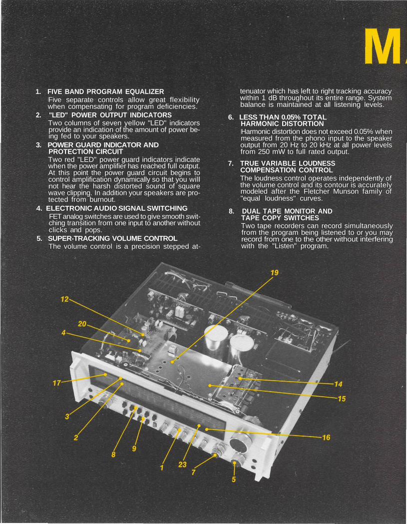
1. FIVE BAND PROGRAM EQUALIZERFive separate controls allow great flexibilitywhen compensating for program deficiencies.
2. "LED" POWER OUTPUT INDICATORSTwo columns of seven yellow "LED" indicatorsprovide an indication of the amount of power be-ing fed to your speakers.
3. POWER GUARD INDICATOR ANDPROTECTION CIRCUITTwo red "LED" power guard indicators indicatewhen the power amplifier has reached full output.At this point the power guard circuit begins tocontrol amplification dynamically so that you willnot hear the harsh distorted sound of squarewave clipping. In addition your speakers are pro-tected from burnout.
4. ELECTRONIC AUDIO SIGNAL SWITCHINGFET analog switches are used to give smooth swit-ching transition from one input to another withoutclicks and pops.
5. SUPER-TRACKING VOLUME CONTROLThe volume control is a precision stepped at-
tenuator which has left to right tracking accuracywithin 1 dB throughout its entire range. Systembalance is maintained at all listening levels.
6. LESS THAN 0.05% TOTALHARMONIC DISTORTIONHarmonic distortion does not exceed 0.05% whenmeasured from the phono input to the speakeroutput from 20 Hz to 20 kHz at all power levelsfrom 250 mW to full rated output.
7. TRUE VARIABLE LOUDNESSCOMPENSATION CONTROLThe loudness control operates independently ofthe volume control and its contour is accuratelymodeled after the Fletcher Munson family of"equal loudness" curves.
8. DUAL TAPE MONITOR ANDTAPE COPY SWITCHESTwo tape recorders can record simultaneouslyfrom the program being listened to or you mayrecord from one to the other without interferingwith the "Listen" program.

9. SPEAKER SWITCHES FORTHREE SETS OF SPEAKERSThree sets of loudspeakers may be used one ata time, two together, or all three simultaneously.
10. SPEAKER PROTECTION CIRCUITSLoudspeakers are protected from burnout bythe Power Guard circuit and also by other cir-cuits that instantaneously disconnect thespeakers in the event of the presence of DC onthe output.
11. PREAMP OUTPUT • POWER AMPINPUT CONNECTIONSBack panel connections provide the ability toinsert room equalizers, reverberation units orother signal processing devices.
12. LOW NOISE ION-IMPLANTED J-FET OP-AMPSNew technology low noise operationalamplifiers give lower noise and greater band-width than conventional devices.
13. ELECTRONIC ACTIVE FILTER ELEMENTS"Active filter" technology is used to generate
the equivalent of the inductors normally used inequalizer filters. This eliminates the humpickup or inductance non linearity that oftenoccurs from conventional inductors.
14. MOS-FET FM FRONT ENDGreat signal sensitivity together with freedomfrom strong signal overload is made possibleby using MOS Field Effect Transistors in theFM RF circuits.
15. ULTRA STABLE LINEAR-PHASEPIEZOELECTRIC FM IF FILTERSThe IF filters are permanently sealed and neverrequire adjustment. The IF response curve isextremely selective because of its very steepslope either side of center and yet it has alinear phase characteristic.
16. AUTOMATIC FREQUENCY LOCKPerfect FM tuning is assured by holding off thetuning lock signal until manual tuning reachesthe center of the FM carrier.
17. WIDE RANGE SIGNAL STRENGTH METERThe signal strength meter pointer responds all

the way from 1 microvolt of antenna noisepickup to over 50,000 microvolts of signalstrength. This allows accurate directionalantenna orientation.
18. FM TUNER SCOPE PLUG IN CONNECTIONSAn oscilloscope or maximum performance in-dicator may be connected easily to adjust adirectional antenna for minimum FM multipathdistortion.
19. FM MULTIPLEX THIRD GENERATIONPLL CIRCUITTri-level electronic switching in the multiplexdecorder gives better separation, lower distor-tion, and superior SCA rejection. Contains tri-level logic for better separation. No inductorsrequired, minimizing drift; Integral lamp drivingcapability to indicate presence of a 19 kc pilotcarrier; Excellent channel separation over theentire audio frequency range; Extremely lowdistortion; Low output impedance; Transientfree mono/stereo switching.
20. MULTIPLEX PILOT ANDCARRIER SUPPRESSION CIRCUITThe 19 kHz pilot and 38 kHz carrier are removedfrom the output thereby eliminating thepossibility of introducing these undesirablesignals to the tape recorder input.
21. "AUTO-ON" AC OUTLETSPower to the entire stereo system can be con-trolled from either the front panel power switchor the power switch on a system turntable.
22. SWITCHED AC OUTLETSAC outlets are provided for accessory equip-ment that turn on and off with your receiver.
23. "LED" FUNCTION INDICATORSSystem status is indicated by long life "LED"indicators.
24. TURN-ON TRANSIENTELIMINATION CIRCUITSSpeaker outputs are connected only afterpower supplies and circuits have stabilizedeliminating turn on thumps or clicks.

TECHNICAL HIGHLIGHTSPhono AmplifierThe phono amplifier uses a new high technology in-tegrated circuit operational amplifier. Its differential in-put stage has been optimized for low noise and lowdistortion performance. Open loop gain of this in-tegrated circuit is 100,000. With high open loop gain alarge amount of negative feedback can be used aroundthe phono amplifier to further reduce noise and distor-tion. The feedback network also provides precisionRIAA frequency compensation. It uses 1% metal filmresistors and 5% poly film capacitors. To achieve lownoise performance it is essential that the feedback net-work be very low impedance. As a consequence, thepreamplifier must be capable of operating as a poweramplifier to drive this impedance. The actual poweroutput capability of this preamplifier stage is morethan 100 milliwatts, a great margin beyond that whichis required.
Input Selector SwitchingElectronic input selector switching uses field effectanalog switches. The mechanical input selector simplyswitches small amounts of DC which turn the FETanalog switches off or on. This design eliminatesdegradation of frequency response and alsoeliminates noise pickup from long signal pathsnecessary with conventional mechanical switching. Itmeans, as well, that switch clicks and pops have beeneliminated.
Equalizer AmplifierThe equalizer amplifier is constructed with ion im-planted junction field effect operational amplifiers.These new devices amplify signals with a 6 dB bettersignal to noise ratio than their bipolar counterparts.Five other operational amplifiers are each arranged incircuit configurations that are the equivalent of seriestuned circuits, one at each of the five center frequen-cies. Each series tuned circuit is inserted via the con-trol potentiometer in either the input circuit or feed-back circuit of the FET op-amp thereby providing aboost and cut capability of 12 dB for each band of fre-quencies. The equalizer amplifier has a gain of 0 dB.
Power GuardAmplifiers are capable of delivering large quantities ofpower when they are driven to clipping. Clipping iscaused when the amplifier is asked to produce morepower output than it can deliver with low distortion. Aclipped amplifier can have more than 40% harmonicdistortion. The extra energy content of the clippedsignal will damage most loudspeakers, particularly thedelicate high frequency tweeters. A new Mclntosh ad-vancement helps protect your speakers from this kindof damage. The MAC 4100 has a built-in waveform com-parator that compares the wave shape of the inputsignal with the output signal. If the disparity betweenthe two signals exceeds 0.5% (equivalent to 0.5% totalharmonic distortion) a front panel signal illuminates inred at the top of the power output indicators. With anyfurther increase in distortion the POWER GUARD cir-cuit will operate. This circuit limits the inputdynamically so that the amplifier cannot be overdriven.POWER GUARD eliminates amplifier output clipping.POWER GUARD does not limit the dynamic range orthe power output of the power amplifier. Clipping oc-curs when an amplifier runs out of power supply. SincePOWER GUARD does not begin to work until this pointis reached, the power capability of the amplifier isnever affected.FM SectionThe FM-IF consists of five integrated circuits and four
piezo electric filters. They combine to give a total gainof over 140 dB. The signal is amplified over a milliontimes. The response curve has nearly linear phasecharacteristics. The skirts of the response curve arevery steep. The maximum width is 170 kHz at 3 dB and500 kHz at 60 dB. The response is symmetrical eachside of the center frequency. The filters are permanent-ly sealed and never require adjustment. They cannotdrift or vibrate out of adjustment. The exceptionallyhigh gain of the five integrated circuits assures hardlimiting at very low levels of input signal.A "phase" or "Foster-Seeley" discriminator has beendesigned to complement the integrated circuit IF sec-tion. The detection output of the discriminator is ex-tremely low in distortion.
FM Stereo Multiplex SectionThe heart of the multiplex section is a new thirdgeneration phase lock loop (PLL) stereo decoder in-tegrated circuit (IC). This PLL IC incorporates twospecial systems, an automatic variable separation con-trol circuit to reduce background noise when receivingweak stereo stations, and a tri-level digital waveformgeneration which eliminates interference from SCAsignals and from the sidebands of adjacent channelFM signals.The variable separation control is operated from the IFamplifier's signal strength detector system. A smoothtransition is provided from mono to stereo or visa versaat weak signal levels to provide the optimum signal tonoise ratio and best stereo separation for the prevail-ing signal conditions. The circuit operates only duringstereo reception, it switches automatically tomonaural if the 19 kHz pilot tone is absent.In the PLL the internal oscillator operates at 228 kHzlocked to the 19 kHz pilot tone. The 228 kHz feeds a 3stage Johnson counter via a binary divider to generatea series of square waves. Suitably connected NANDgates and exclusive OR gates produce the tri-leveldrive waveform for the various demodulators in the cir-cuit. The usual square waveforms have been replacedin the PLL and decoder sections by tri-level waveforms.These tri-level forms contain no harmonics which aremultiples of 2 or 3. This eliminates frequency trans-lation and detection of interference from the side-bands of adjacent stations since the third harmonic ofthe sub-carrier (114 kHz) is excluded and interferencefrom SCA broadcasts since the third harmonic of thepilot tone (57 kHz) is excluded. Unwanted spuriousaudible components and phase jitter in the PLL withconsequent intermodulation distortion are inherentlyeliminated by this technique.Additional advantages of the phase locked loop stereodemodulation are the elimination of inductors tominimize drift, integral lamp driving capability to in-dicate the presence of the 19 kHz pilot carrier, ex-cellent channel separation over the entire audio fre-quency range, extremely low distortion, low output im-pedance, and transient-free mono/stereo switching.After multiplex detection, 19 kHz pilot and 38 kHz car-rier suppression circuits are used to prevent taperecorder interference.The FM muting circuit is unusual. It operates both bydetecting ultrasonic noise and by sensing correct tun-ing of the detector circuit. To 'un-mute' it is necessaryfor the signal to have an adequate signal-to-noise ratioand to be tuned to the center of the FM carrier. TheMUTING circuit can be activated or defeated by thefront panel muting pushbutton. The switching on andoff of the audio signal is done with FET analog switches.

MAC 4100PERFORMANCE
LIMITSPerformance limits are the maximum deviation fromperfection permitted for-a Mclntosh instrument. Wepromise you that when you purchase a new MAC4100 from a Mclntosh Franchised dealer it will becapable of performance at or exceeding these limitsor you can return the unit and get your money back.Mclntosh is the only manufacturer that makes thisstatement.
AMPLIFIER SECTIONPOWER OUTPUT100 watts minimum sine wave continuous averagepower output, per channel, both channels operating in-to 4 ohms 20 Hz to 20 kHz, with no more than .05% totalharmonic distortion75 watts minimum sine wave continuous averagepower output, per channel, both channels operating in-to 8 ohms 20 Hz to 20 kHz, with no more than .05% totalharmonic distortionOUTPUT LOAD IMPEDANCE4 ohms, 8 ohmsRATED POWER BAND20 Hz to 20 kHzTOTAL HARMONIC DISTORTION.05% maximum at any power level from 250 milliwattsto rated power per channel, 20 Hz to 20 kHz, both chan-nels operatingINTERMODULATION DISTORTION.05% maximum at any power level from 250 milliwattsto rated power per channel both channels operating forany combination of frequencies 20 Hz to 20 kHzFREQUENCY RESPONSE20 Hz to 20 kHz +0, -0.5 dB at rated powerHUM AND NOISEPower Amp: 100 dB IHFA, 95 dB unweighted, belowrated outputTape and Aux Input: 95 dB IHFA, 90 dB unweighted,below rated outputPhono Input: 90 dB IHFA, 80 dB unweighted, below 10mV inputDAMPING FACTORGreater than 30INPUT SENSITIVITY AND IMPEDANCEPower Amp: 2.5 V; 22,000 ohmsTape and Aux: 250 mV; 100,000 ohmsPhono: 2 mV; 47,000 ohms; 87 pFTAPE OUTPUTTuner: 1.0 V at 100% modulation (FM)Tape: 250 mV with rated inputPhono: 250 mV with rated inputPROGRAM EQUALIZER± 12 dB at 30, 150, 500, 1500, and 10,000 Hz
FM SECTIONSENSITIVITY2mV (11.2 dBF) IHF minimumSIGNAL TO NOISE RATIO70 dB IHF minimumHARMONIC DISTORTIONMono: 0,18% IHF maximumStereo: 0.38% IHF maximumFREQUENCY RESPONSE20 Hz to 15kHz +0, -1 dBCAPTURE RATIO1.8 dBSELECTIVITY75 dB IHF minimumSPURIOUS REJECTION90 dB IHF minimumIMAGE REJECTION80 dB IHF minimumSTEREO SEPARATION45 dB minimum at 1 kHzSCA REJECTION60 dB minimum
AM SECTIONSENSITIVITY75 mV IHF (External antenna)SIGNAL TO NOISE RATIO45 dB minimum IHF, 55 dB at 100% modulationHARMONIC DISTORTION0.8% maximum at 30% modulationFREQUENCY RESPONSE3500 Hz @ -6 dBADJACENT CHANNEL SELECTIVITY30 dB minimum IHFIMAGE REJECTION65 dB minimum, 540 kHz to 1600 kHz
GENERALSEMICONDUCTOR COMPLEMENT45 Transistors31 Integrated Circuits62 Diodes
1 Silicon Controlled RectifierMECHANICAL INFORMATION
SIZEIn cabinet: 18-5/8 inches (473.1mm) wide, 6-1/2 inches(165.1mm) high, 15-1/2 inches (393.7mm) deep. Withoutcabinet: Front panel measures 17-9/16 inches(446.1mm) wide by 5-1/4 inches (133.4mm) high.Chassis measures 17-1/8 inches (435mm) wide by4-15/16 inches high (125.4mm) by 13-1/2 inches(342.9mm) deep. Knob and handle clearance required1-1/16 inches (27mm) in front of the mounting surface.FINISHFront panel is clear anodized to produce a brushedsatin - silver finish with black anodized trim. Cabinet iswalnut grained vinyl.WEIGHT42 pounds (19 kg) net56 pounds (25.4 kg) in shipping cartonThe continuous improvement of its products is the policy ofMclntosh Laboratory Incorporated, who reserves the right to improvedesign without notice.
FRANCHISED DEALER
039273
MCINTOSH LABORATORY INC.2 CHAMBERS ST., BINGHAMTON, N.Y. 13903-9990
607-723-3512Printed in U.S.A.