the magazin for large plastic pipe technology /2011 improfil
TRANSCRIPT

IMPROFILStorage tanks and special apparatus
Pipe Application / Egypt - „Primary care families“
Krah pipes goes crazy - apps beside the applications
See also: ImProfilof:SandraPerez/KrahAméricaLatina,BuenosAires ATVA127StandardVS.AWWAM55manual -MainDifferences in theStatic CalculationMethodologyforFlexiblePipes
Welcome to the 4th issue of ImProfil
Dear Members of the Krah Community and friends and interested people,
The year 2011 has gone so fast again and we are now publishing already the 4. Issue of our “ImProfil”, which according to your feedback has been quite well-received and we are looking for-ward to improving ourselves with the help of your interesting ar-ticles and news related to pipe products in 2012!
Besides several technically interesting articles you will find some motivating pictures which show what else can be done with and
from Krah pipes – maybe you can build your children a Christmas present yourself this year ;)
Very soon, in the beginning of 2012 we will offer a print version „BestOf“ of all Improfil Issues 2011, which can be ordered for free! Don´t miss this offer and send your email with the reference: „BestOf“ to [email protected]. Furthermore we have just produced our 750. mandrel which com-bines the latest innovations and best quality with the lowest price. For further information on our promotion please refer to http://www.krah.net/en/home/news-archive.html
Finally, there is no time more fitting to say „Thank You“ and to wish you a Happy Holiday Season and a New Year of health, hap-piness and prosperity.
Looking forward to cooperating with you in 2012!
With kind regards
Alexander Krah / CEO of Krah AG
Themagazinforlarge Plastic Pipe Technology (uptoDN4000mm)04/2011

2
Themagazinforlarge Plastic Pipe Technology (uptoDN4000mm)04/2011
Storage tanks and special apparatus
Tanks for storage of liquids are required in all areas of pu-blic life. Constructions made of thermoplastic plastics are playing a decisive role on this. Beginning with the traditional bucket, which are belonging to our lives since the earliest initi-ations of plastics technology, up to the 100 m³ storage tank for chemicals and hazardous liquids – there is no way of avoiding constructions made of polyethylene and polypropylene today. Particularly if the cylinder barrel is made of helical extruded pipes, the flexible wall construction (profiled wall structure, multi layer, etc), which comes along with the manufacturing method, in connection with new generations of raw materi-al, continuously opens up new possibilities of solution for the construction of tanks. Thereby new possibilities to connect stability, resistance, long-life cycle and chemical resistivity as well as cost-effectiveness are established. This makes it possi-ble to incorporate them suggestively into construction.
A multitude of tanks is engineered in vertical form. The bottom construction is carried out as flat, beveled or conical bottom. The roof construction in turn can be engineered open – with or without reinforced edges, with cone-type roof or with flat roof.
Horizontal tank constructions are also applied, whereas the calcu-lation and especially the construction can be much more complex. Horizontal tanks are: - aboveground with supports- aboveground in shells - in some extent carved in the ground (supporting angle mostly 90°-120°)or subsurfacelly installed.
The most common mounting form is for sure the vertical, cy-lindrical tank with a flat top, which cylinder is made of helical extruded pipes. The applied load on the tank constructions can normally be derived from the operating conditions.
Attention should be paid to the fact that the tank often is part of a complex construction, which means, it may need suitable additi-onally installed equipment. Tanks which are for example used in chemical engineering, in filling or decanting stations or as process containers, are often additionally equipped with stirring devices, pumps, metering or tempering devices. The resulting static and dynamic loads have to be considered just as these following ge-neral points:
Typical storage tank for hazardous liquids:
Storage tanks 68 m³, manufactured by PCT, Belgiumdesign acc. DVS 2205
manufactured by PCT, Belgiumtemperature design: TA: environmental temperature TZ: temperature cylindric wall TD: temperature roof TM: temperature liquid

3
Themagazinforlarge Plastic Pipe Technology (uptoDN4000mm)04/2011
...
Hydrostatics and operating pressuresHydrostatic conditions result from the kind of medium (density, viscosity) and the conditions of filling (filling cycle, filling level, duration of filling).The resulting operating pressures are decisive for the dimensioning of the cylinder wall, cylinder bottom and roof, as well as for additionally installed equipment. Additional pressures (negative or positive pressure) can be produced by the action of emptying and filling or by external influences like chan-ging weather conditions or wind load.
Chemical resistanceThe medium which is filled in can influence the stability and strength durability of the chosen material of the tank. Although Polyethylene and Polypropylene generally have got a very good resistance to a multitude of acids and bases, there are limitations and boundaries of resistance. These boundaries can furthermore be changed by the influence of temperature and reaction time. In many cases the reduction ratio for the used medium is to be found in literature and standards, which make dimensioning easier.
TemperatureThe behavior of Thermoplastics is depending on temperature, with increasing temperature tolerable stability and stiffness decre-ase. This behavior has been adequately proven and follows prin-ciples, which allows an exact calculation. The required material data is provided by manufacturers of raw materials and is the base for the dimensioning of pressure pipe systems, sewers etc. The temperature of the cylinder wall is influenced by the temperature of the medium on the one hand and by the ambient temperature on the other. Normally the average temperature is used for the di-mensioning. This procedural method, in which the aspect of time also has to be taken into account, works best if there are only minor or median differences in temperatures. A detailed observa-tion of material property is useful if there are big differences in temperature.
Influence of weather According to the installation site different climatic conditions can occur. If it is installed inside a building there has to be paid atten-tion only to the ambient air temperature, other climatic conditions can normally be excluded or have just an extremely alleviated effect. But outside buildings wind, sun, precipitation and ambient temperature have to be considered. The load by weather is natu-rally dependent on season; furthermore different regions have to
be considered differently. Regions are often divided into different areas of weather, for which the frequency and intensity of weather conditions have been empirically defined. A change of weather conditions caused by climate change should be noted if a long term dimensioning is carried out.
Potential danger Consideration of danger is the central point of all considerations concerning safety, especially if handling with chemicals or other hazardous substances. Here we differentiate between dangers for: persons, subjects and environment. Regulatory requirements dif-fer a lot in the countries of the world, which has to be paid attenti-on to when defining values and rules for safety. That is why there are no readable universal laws for safety.
Operating conditions are also very important because it is a dif-ference if the load is static or varying a lot. Protections like over-flow protection, devices for detecting leakages and alarms, as well as the possibility of remote supervision have to be clarified from case to case, but are in any case good instruments to reduce the potential danger. Normally a collecting device or tank is prescri-bed for dangerous substances, which influences the static load of wind, precipitation and solar radiation in addition to security.
Dimensioning of tanks Dimensioning of tanks takes place by using principles of strength of materials and plastics technology. Thereby we can fall back on the experience of more than fifty years. For modern pipe material normally corresponding curves and tables are provided by the ma-nufacturers when launching a product, from which you can read necessary figures for short- and long-term usage. In terms of static calculation and temporal scale, you often differentiated between applications. Calculation therefore normally is scheduled to run for 10 or 25 years, in individual cases for 50 years.
In order to be able to get needed material characteristics for the respective time of calculation, you can, concerning to the consi-deration of load, fall back on hydrostatic strength diagram, which have been determined exemplarily on an axial extruded pipe. The calculation of stability is carried out with material properties, which are based on creep modules, which can be extrapolated from measurement data form up to 10000h. Security of such ex-trapolations for pipe material made of polyethylene is given by continuing experience for many decades.

4
Themagazinforlarge Plastic Pipe Technology (uptoDN4000mm)04/2011
...
For raw materials with laboratory confirmed long term behaviour (hydrostatic strenght curves acc. international standards ISO 1167), a sufficient accuracy of extrapolation to 50 Jahre from 2000 h datas is approved. This means a extrapolation for 2,5 decade.
The first storage tanks made of polyethylene were produced in 1950s. Since this time computer programs for static calculation have gained credibility on the market, which can limit calculation costs. Standards and guidelines ensure the required standardiza-tion for this important market segment of plastics industry. Cal-culation rules are, inter alia, described in detail in standard EN 12573 or DVS 2205 part 2. A simple wall dimensioning can often be estimated with sufficient accuracy by carrying out a calculation of stability to internal pres-sure on the one hand and to vacuum on the other.
Firstly must calculated with the traditional equation for inner pressure (acc. Peter Barlow) the required cylinder wall. The
inner pressure depends from filling height, density of the liquid and permitted load. This can be conducted in different heights of the cylinder to get a staged and with it cost-efficient wall structure.
The permitted stress is the result of typical creep rupture curves (hydrostatic stenghts diagram) for the raw material, in considera-tion of the safety factor and the reduction coefficient for the speci-fic ductility ( depending on the temperature), the joint factor (de-pending on the kind of welding) and the chemical loading by the liquid (tables of operating experience, inter alia DVS and DIBt, Germany). For the consideration of the bending moment you have to choose an additional factor, which takes the constraint of elon-gation of the cylinder in the area of joint between cylinder and bottom plate into account. The constraint of elongation respec-tively the stiffness depends by the thickness of the bottom plate. In practice this factor is between 1 (membrane bottom plate) and 1,82 (fixed bottom plate).
S: safety factor [-]σ: load from hydrostatic strength diagram for the present temperature [N/mm²]A1: reduction coefficient specific ductility [-] A2: reduction coefficient ambient medium [-]fs: long duration welding factor for homogenously manufactured helical extruded pipes = 1
p: hydrostatic pressure[N/mm²]g: acceleration of gravity [m/s²]Forρ: density of the medium [kg/cm³]sZS: minimum wall thickness for the consideration of loads [mm]C: factor for bending moment [-]di: inside diameter [mm]

5
Themagazinforlarge Plastic Pipe Technology (uptoDN4000mm)04/2011
...
Including the calculation of stability against vacuum, which can for example arise during emptying the tank or be caused by in-creasing wind suction, a good approach towards the statically re-quired wall thicknesses can be reached. The minimum value for this vacuum, which could arise, has been set at 0,0003N/mm² by guideline DVS 2205. Equation for buckling of cylinders:
ii
TK
uzIZB d
dE
phASs C ⋅
⋅
⋅⋅⋅⋅= °
∑4,0
279,0
sZB: minimum wall thickness for buckling load [mm]S: safety factor [-]A2I: reduction coefficient ambient medium for consideration of stability [-] hZ: high of cylinder [mm]Σpu: ^total vacuum loads [N/mm²]EK: creep modulus for period under consideration and temperature [N/mm²] di: inside diameter [mm]
A concluding calculation can not be replaced by such a first consideration, as described before. However, it provides a good and quick indication to the required construction.
At Krah Community (www.krah.net) an Excel spread sheet can be downloaded by members for calculation of vertically tanks!
Design details for production of tanksNormally, cylinder are fastened onto the bottom plate with double fillet weld, whereas a ≥ 0,7 x sB . The bottom thickness sB should always be less than the thickness oft he cylinder sZ. A rule of thumb for bottom plate dimensioning is sB = 0,8 x sZ.
To give tanks the required stability, especially for use outdoors, the bottom plate often is anchored in the foundations. The ancors must be designed against the worst case of load. This concerns primarilydimensioning against wind and the resulting bending moment but also increasing pressure fluctuations can affect the load conditions. If anchors are necessary, at least four fastening anchors are needed to ensure a steady load bearing. The anchoring logically is to be carried out with help of separate fastening anchors so that the tank can move/slide sideward and relax. To ensure that be bottom plate of the tank can slide, an additional plastic plate with a thickness of app. 2 mm below the base is recommended. In this way no elongation under the influence of temperature or change of load can result in avoidable additional loads.
Anchoring of the bottom
For fluidic and procedural reasons, the usage of tanks often leads to different bottom constructions than the typical flat-bottom (beveled or conical bottom,...). These geometries have to be

6
Themagazinforlarge Plastic Pipe Technology (uptoDN4000mm)04/2011
statically calculated and professionally integrated into the overall construction by welding just as a flat-bottom. The accessibility of the welding zone is partly complicated and places special demands on welder and welding apparatus.
a = 0,7 x s3 a ≥ 60° f = 0,5 x s3
a < 60°
Reinforcement of the rimTanks, which are open to the top, need to have a reinforced rim. The minimum wall thickness, which is the result of the hydrostatic, does not lead to a sufficient stiffness, especially when talking about partial filling. There are several solutions to avoid this. The most useful variation is to use the flexibility in manufacturing of helical extruded pipes and to thicken the wall thickness during production at the rim of the container. A retrofitting solution is the welding of a separate stripe or the attachment and welding of an axial extruded pipe, which has been slotted before.
Roof constructionsIf containers, made of thermoplastics, are designed with a roof, normally conical roofs with a roof inclination of 15° or ripped flat roofs are used. A stability check is to be carried out for the deadum.
Special attention has to be paid to arising operating- and ambient temperatures. An accessibility of thermoplastic roofs is usually not intended, according to the safety regulations, but is still guaranteed by grates on separate platforms or by suitable ladders. When used in connection with platforms and ladders you have to take the different elongation by temperature of steel and thermoplastics into account. In either case, suitable slide bearings in the construction are needed to avoid loads.
...

7
Themagazinforlarge Plastic Pipe Technology (uptoDN4000mm)04/2011
Section through flat roof with two stiffeners and bulkheads,with two variants for bearing flat roof on the cylinder:
Variante 1:
SV ≥ SD and SV ≥ 10 mm C ≥ 5 x SD and C ≥ 80 mm a1 ≥ 0,5 x min (SD, Szi)a2 ≥ 0,5 x Szi
Variante 2:
a2 ≥ 0,5 x SzminSmin ≥ min (Szi, SD)
Conical roof - Different variants for bearing roof on cylinder
Lifting lugsTo make the lifting of a tank easier, two lifting lugs are welded on it. The dimensioning and the choice of the safety factor have to take account of possible dangers of floating loads. Account should be taken to the weight of the tank plus mounting parts. The required thickness of the lifting lug is situated within following limits: bÖ > sz and bÖ < 3 x sZ
The use of traverses protect the rim of the tank against avoidable deformations and it guaranty a vertical lifting without additional loads. It is important to note that in setting up a tank, which was transported in a laying position, the lifting lug is temporary loaded by thrust, torsion and bending. Furthermore, the hole diameter hast to be coordinated to the diameter of the shackle, to avoid inadmissible bearing stresses. Design of lifting lugs:
...

8
Themagazinforlarge Plastic Pipe Technology (uptoDN4000mm)04/2011
NozzlesNumber and suitable dimension of nozzles is important for the dimensioning of the wall thickness, because every cutout can present a weakening. As smaller the nozzle, as smaller the weakening. By the use of DVS 2205 for dimensioning, nozzles in the cylinder wall are just permitted up to a diameter of 160 mm. Especially the lower section near to the bottom should be avoided if possible, because of the stress and the disability of elongation. If using storage tanks, the nozzles should be integrated into the roof, which requires no special calculative proof. This applies in particular to manways and nozzles with large diameter. The weld has to be made with fillet welds on both sides, which requires a minimum distance to the basement or installed equipment.
Nozzle in the cylinder shell:
Welding in cylinder wallsIf cylinder walls are extended (helical extruded pipes can be manufactured in homogenous units up to a length of 6 m), following joints made by welding can be chosen dependent to the wall thickness constellation.
Staged walls: with a1 = 0,7 x s
same wall thickness
Double wall tanks for hazardous liquidsAs already mentioned, you need to make special arrangements for dangerous liquids where regulatory requirements differ in the countries. Widely similar is the requirement for a safety tank or a collection container, in which liquids can safely escape if there is a leakage. Tanks fabricated out of helical extruded pipes are available as “tank in tank” solution. For this purpose you integrate a hollow profile into the cylinder wall, which separates the inner wall from the outer wall on the one hand, which gives them different functionsand serve as a leakage warning cavity on the other. A leakage sensor can be arranged in a way that it gives alarm when there is only a minimal leakage, which ensures best reaction time!
The inner wall performs a protective function and has to be statically designed in a way that it – supported by profile and outer wall – can cope with hydrostatic pressure. It also needs to have a suitable wall thickness to guarantee a proper welded joint to the double bottom.The outer wall has to carry the total static load, which is transmitted from the inner wall over the profile outwards, which is why it is normally dimensioned in these premises. The outer wall normally is not exposed to long time affect by chemicals or hazardous liquids, which can be taken into account when calculating, what permits significant savings in the wall thickness. Moreover, the advantage is space-saving and the cheaper manufacturing.
Dipl.-Ing. Stephan FüllgrabeManaging Director / Plaspitec GmbH
...
9
Themagazinforlarge Plastic Pipe Technology (uptoDN4000mm)04/2011
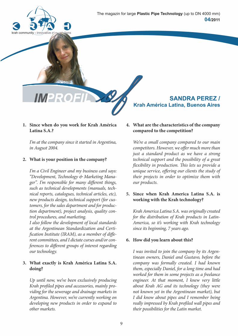
1. Since when do you work for Krah América Latina S.A.?
I’m at the company since it started in Argentina, in August 2004.
2. What is your position in the company?
I’m a Civil Engineer and my business card says: “Development, Technology & Marketing Mana-ger”. I’m responsible for many different things, such as technical developments (manuals, tech-nical reports, catalogues, technical articles, etc), new products design, technical support (for cus-tomers, for the sales department and for produc-tion department), project analysis, quality con-trol procedures, and marketing. I also follow the development of local standards at the Argentinean Standardization and Certi-fication Institute (IRAM), as a member of diffe-rent committees, and I dictate curses and/or con-ferences to different groups of interest regarding our technology.
3. What exactly is Krah América Latina S.A. doing?
Up until now, we’ve been exclusively producing Krah profiled pipes and accessories, mainly pro-viding for the sewerage and drainage markets in Argentina. However, we’re currently working on developing new products in order to expand to other markets.
SANDRA PEREZ /Krah América Latina, Buenos Aires
4. What are the characteristics of the company compared to the competition?
We’re a small company compared to our main competitors. However, we offer much more than just a standard product as we have a strong technical support and the possibility of a great flexibility in production. This lets us provide a unique service, offering our clients the study of their projects in order to optimize them with our products.
5. Since when Krah America Latina S.A. is working with the Krah technology?
Krah America Latina S.A. was originally created for the distribution of Krah products in Latin-America, so it’s working with Krah technology since its beginning, 7 years ago.
6. How did you learn about this?
I was invited to join the company by its Argen-tinean owners, Daniel and Gustavo, before the company was formally created. I had known them, especially Daniel, for a long time and had worked for them in some projects as a freelance engineer. At that moment, I knew very little about Krah AG and its technology (they were not known yet in the Argentinean market), but I did know about pipes and I remember being really impressed by Krah profiled wall pipes and their possibilities for the Latin market.

10
Themagazinforlarge Plastic Pipe Technology (uptoDN4000mm)04/2011
...
7. Which Krah machines does Krah America Latina S.A. own until now?
We own one machine KR700.
8. What do you call your „Krah pipes“? (brand name)
We call the profiled wall line as “Krah Profil” pipes. The idea was to maintain a clear reference to Krah in the product name, being ourselves a Krah company.
9. How many projects you have been realized with these so far?
Our products have been installed in over 90 pro-jects now, totalizing more than 140 km of ins-talled pipes, including the first 2 experiences with HDPE outfalls in Argentina.
10. What is your experience retrospectively?
My experience with Krah technology, as I already said, comes from its beginnings in Argentina, so I lived all the process, since the KR700 installation, through the study of the product, it’s presentation for the Argentinean market, the first projects, etc, etc. So far, it’s been a great experience that made me grow up both professionally and personally. With regard specifically to Krah’s technology, I think the flexibility given by the production sys-tem and its continuous upgrades are the mayor advantages, as they let us be constantly optimi-zing our products or creating new ones, offering the client always the best possible choice.
Sandra personal
Family: I’m married with Pablo (another engineer like me) and we have two daughters: Lucia (4 years old) and Victoria (1 year old)
In my spare time… Unfortunately, I do not have much spare time at the moment as my kids are too young. How-ever, when I can, I like to go to the movies, spend time with friends or travel. I also like sports a lot, like skating or skiing.
I am just reading …Dan Brown’s “The Lost Symbol”. But I’m rea-ding it very slowly, as it’s hard for me to find the time these days.
I can laugh about: Many things: a funny movie, a funny TV show and, mostly, my kids’ ideas and jokes.

11
Themagazinforlarge Plastic Pipe Technology (uptoDN4000mm)04/2011
Pipe Application / Egypt - „Primary care families“
With approximately 8 million people Cairo (Egypt) is the most populous city in the Arab world. Today the metropolitan area of Cairo is even home to around 25 million people, which means that the provision of clean drinking water and disposal of wastewater is one of the biggest challenges of this region. To address this problem the government has embarked on the project „Primary care families“, some time ago. This project aimed to support people, „who had lost their homes in cata-strophes or who lives in very bad conditions.“
As part of this project a sub-project for 12,500 residential units and 60,000 residents was planned and completed successfully 30 km south from the city center. This could be realized in collabora-tion with project partners as follows• EGEC (engineering consultancy) - www.egec-xprt.com• Arab Contractor (Contractor) - www.arabcont.com• Krah New Mena Plast (pipe manufacturer) www.krahmisr.com
To offer help to the people as quickly as possible, the entire project was under a very high time pressure. That’s why the estimated construction period had been one of the most important selection criteria for products and companies.
The company New Mena Plast / Cairo could meet all necessary demands of the project. It was advanta-geous that the selected and used profiled Krah pipes (made of polyethylene) could be produced directly at Mena New Plast / Cairo, thus the delivery time could be kept very low. The lightweight but very sta-ble PE-profile pipes - with a weight of well under 50 kg per meter - could be handled on the construction site without the use of special equipment.
The complete pipeline of length: 3 Km divided bet-ween 500, 800 and 1000 mm pipe diameters. The du-rable welded joint was made by Krah welding equip-ment simultaneously with the pipe installation in less than half an hour. Thus the construction process was not disturbed and the installation time could be re-duced to a minimum. Per day and welding machine more than 60 meters were installed. The pipes have been statically calculated according to the standard ATV 127. Therefore, the occurring loads as well as the soil and installation conditions were considered. The pipes were laid in a trench 1.2 to 2.5 m width up to 8 meters depth. Since polye-thylene is a flexible pipe material which adopts to stress, we can by now expect a lifetime of more than 100 years. The homogeneous welded joints are very beneficial to lifetime of the pipes, as no additional seals must be used and the entire piping system is

12
Themagazinforlarge Plastic Pipe Technology (uptoDN4000mm)04/2011
...
completely homogeneous and dense. The tightness is especially important to protect groundwater from contamination and thus prevent disease. So it was checked and verified successfully in 50 meter intervals. With the help of static analysis a solution to short term changes in environmental conditions can be found.
Because the pipeline route had to be rescheduled, very high traffic loads had to be considered for a subsection below a highway. Sin-
ce flexible pipe systems create a synergistic association with soil, the installation conditions have been optimized so that even here an optimal load distribution could be ensured.
More information:Krah New Mena Plast / Peter Youssef
www.krahmisr.com

13
Themagazinforlarge Plastic Pipe Technology (uptoDN4000mm)04/2011
ATV A127 Standard VS. AWWA M55 manual Main Differences in the Static Calculation Methodology for Flexible Pipes
IntroductionThe purpose of this article is to set up the main differences between two popular methods worldwide for performing sta-tic verifications of HDPE flexible pipes, i.e. between the me-thod given by the ATV A127 standard („Guidelines for Static Calculations on Drainage Conduits and Pipelines“) and the method established by the American Water Works Associa-tion (AWWA) more specifically in its manual M55 („PE Pipe Design and Installation“).
Brief review about the related methodologies
The ATV A127 is a standard of German origin and its latest ver-sion dates from the year 2000. It is widely used in Europe and its content exclusively covers the methodology for calculations of all kinds of pipes.
AWWA M55 is not a standard, but rather a design manual accor-ding to the recommendations of the American Water Works Asso-ciation (AWWA) covering all relevant aspects of the design and installation of HDPE pipes. The recommended methodology of structural calculation is one of the ten chapters that the manual contains and is exclusive for HDPE pipes (although the guidelines are common to the AWWA manuals of other types of pipes). The methodology basis used in this manual is the most used, almost exclusively, in the Americas.
COMPARISON
Basic Ddifferences in the methodology of calculation
For the main basic differences between both documents, it can be mentioned:
I. The ATV A127 methodology aims to be universal, i.e. for any kind of pipe, regardless of the material or its status as „rigid“ or „flexible“. The AWWA M55 methodology, on the other hand, stands exclusively for the case of flexible pipes.
II. Soil load calculation is more conservative in AWWA, due to the fact that this manual does not consider, as ATV does, the “arc” effect that usually takes place for flexible pipes (redu-cing the weight of the soil prism right above the pipe).
III. Another important difference is the way in which each me-thodology analyses the distribution of the filling soil load around the pipe. Both methodologies are based on the theory of M.G. Spangler. However, while the M55 AWWA manual takes this theory without modification assuming, as Spangler, that no ho-rizontal active pressure will develop on the pipe, the A127 ATV standard does take into account the influence of this horizontal active pressure.
IV. The ATV methodology is much more detailed regarding trench-pipe interaction and does a deeper analysis about the in-tervention of each of the variables. The main difference in the trench scheme that analyzes each methodology is based on the consideration of the different zones of ground: while AWWA only differences between natural and filling soil (assigning different modules of soil reaction EN‘ and EE‘ respectively), ATV divides the trench in four areas:
- Zone 1: filling soil above the pipe (E1) - Zone 2: filling soil below and to the sides of the pipe (E2) - Zone 3: natural soil on the trench sides (E3) - Zone 4: natural soil below the trench (E4)
In both cases an influence of the native soil in the global pipe-trench structural package is considered, but the way of analysis for each methodology is different.
Filling Soil Load for AWWA Filling Soil Load for ATV

14
Themagazinforlarge Plastic Pipe Technology (uptoDN4000mm)04/2011
...
V. While AWWA methodology does not distinguish bet-ween vertical or sloping trench walls, in the ATV methodology the inclination angle of the walls of the trench is an important variable.
VI. In the ATV the use of sheet piling or coatings to contain the walls of the trench, and its removal methodology once instal-led the trench fill, acquires importance. However, these conside-rations are not taken into account by AWWA at any time.
VII. The ATV A127 methodology is more conservative when coming to the treatment of the „long term“ analysis, espe-cially in the case of thermoplastic materials, as it considers that the pipe will be permanently loaded in time and, therefore, it has to be always verified for every long term load using the materials long term properties (creep module, ultimate stresses).
The methodology of the AWWA M55 manual, on the other hand, considers that, against the external vertical loads, the pipe will not always be requested in the long term, but only when the stiffness of the pipe exceeds 25% of the rigidity of the filling soil of the trench. This is based on the theory that, if the pipe behaves like flexible and it is well installed (i.e. has a good soil filling around, compacted to an adequate density) it shall transmit the vertical loads to the lateral filling soil and will therefore not be requested permanently, but rather by „discrete“ load pulses, against which, the material of the pipe will always respond with its short term resistance. However, if the stiffness of the pipe is close to the rigidity of the filling soil, it will behave more like a rigid pipe and will have to withstand the burdens in its own structure on an ongoing basis, responding, as a result, with material’s long term parameters.
VIII. ATV’s treatment of buckling verification is more con-servative, especially in the case of existing groundwater, as it ad-opts the criteria that the pipe’s confinement due to the filling soil will never have any influence in the pipe’s resistance. On the other hand, AWWA only considers that the pipe’s confinement does not fully act when the cover depth is low, because it cannot develop properly, but it’s help on pipe’s buckling resistance is always con-sidered for cover depths equal or greater than 1.20 meters.
Differences in the application of each method
When applying each method in performing static calculations of pipes, the following differences can be observed:
I. The ATV requires a prior knowledge and/or definition of a large number of installation parameters (many of them of dif-ficult definition in advance). On the other hand, AWWA requires less and easier to estimate data.
II. The ATV methodology is more complex to understand and to apply than the AWWA methodology.
III. The ATV methodology presents a strong dependence of the results with some variables (such as the methodology of instal-lation of the filling soil and/or the slope angle of the trench walls) that the AWWA methodology has directly no consideration of.
IV. In the ATV methodology there’s a great variation in the results when varying the pipe’s bedding angle. This does not happen in AWWA, where, despite the fact that the bedding angle is actually considered, its real influence on the final results is very low.
V. In all cases, especially in the cases where there´s groundwater above the pipe, ATV’s required ring stiffness is far superior to the one required by AWWA. Generally this is because of the differences in the treatment of buckling verification bet-ween both methodologies.
Example analysis
A priori, given the great variability existing between the para-meters considered by each methodology, it’s virtually impossi-ble to make a detailed theoretical comparison between the two.
EN’ EE
’
E2
E1
E3 E3
E4 Trench scheme for AWWA Trench scheme for ATV

15
Themagazinforlarge Plastic Pipe Technology (uptoDN4000mm)04/2011
...
However, what can be analyzed are the results that occur in one or another case.
For this, a brief analysis was performed based on Krah’s profiled wall pipes offer, making structural verification of buried pipelines using both methodologies, for pipe’s diameters from 400 to 1600 mm, varying the cover height between 1 and 9 meters and in the 2 following conditions: a) without groundwater and b) with a groundwater level at a 0.5 meters depth below ground surface. In both cases, a native cohesive soil (with medium to low stiffness), a granular filling soil compacted up to 90% of normal Proctor Density and the heavier vehicular traffic considered by each me-thodology (AASHTO H20 truck for AWWA and HGL60 truck for ATV) with rigid pavement were adopted. In each case the most appropriate Krah pipe (the one that verified all conditions) was selected and its ring stiffness was registered, observing the fol-lowing:
a) The pipes that verified ATV’s conditions required a much higher ring stiffness (in the order of 40 to 260 % higher) than the pipes that verified AWWA’s conditions.
b) The influence of groundwater, especially for long term buckling verification, probed to be very important in the ATV, re-sulting pipes of a very high ring stiffness for big cover depths in the presence of groundwater pressures. AWWA methodology verification for long term buckling in the presence of groundwater was also defining in most cases, but without reaching the magni-tudes of ring stiffness of ATV.
In the figure below an example can be seen of the obtained results (i.e. the required nominal stiffness according to ISO 9969) for DN = 1000 mm pipes, with the following color references:
- Light blue: ATV’s verifications without groundwater- Dark blue: ATV’s verifications with groundwater- Light red: AWWA’s verifications without groundwater- Dark red: AWWA’s verifications with groundwater
Final conclusions
The ATV presents as a more complete and detailed calculation methodology, but is also more conservative, it’s difficult to get all the required data for its implementation and the results penalize the pipe much more than AWWA. Therefore, from the point of view of the economy of a project, the choice of AWWA’s metho-dology seems more appropriate.
However, what should be the choice of one or another methodo-logy for calculating is the accuracy of each in terms of its correla-tion with reality. And that’s the big question that is still matter of vigorous discussions up to this date, without a clear or definitive conclusion, because pipes being calculated by one or the other method had presented in both cases very good field performances over the last decades. So nowadays, unless there’s an obligation to attend to a specific standard, the election is at the discretion of the professional in charge of each project in particular.

16
Themagazinforlarge Plastic Pipe Technology (uptoDN4000mm)04/2011
Krah sewage line for water treatment plant - obregon sonora / mexico December 1st, 2011.Ciudad Obregón, Sonora, una ciudad de 475,000 habitantes ubicada en el Noroeste de México, es una de las ciudades con mayor porcentaje de agua de drenaje tratada en el país, lle-gando a 95% , ahora la tecnología Krah ha entrado a este mercado exitosamente.
Ciudad Obregon, Sonora a city of 475,000 people in the Northwe-stern part of Mexico is one of the cities, that has the highest per-centage of treated water in the country, treating around 95% of its sewage water, and now Krah technology has entered this market successfully.
OOMAPAS DE CAJEME, the water organism in Obregon, wan-ted to replace several sewage lines that converged in the South Water Treatment Plant of the city, which has a capacity of 735 liters per second and started its operation in August 1997.
The installation conditions were 5 meter in depth, clay soil, and high phreatic (groundwater) surface at 20 cm from the ground soil. Also the lines were to be installed near agricultural fields so this created more water in the soil because of irrigation.
OOMAPAS had already tested a 60 inch corrugated pipe from the brand ADS, which had problems and collapsed in some sections, and Krah Mexico proposed a 60 inch pipe with an SN 3, which performed very well and also reduced the size of the trench they needed to open having savings in their installation costs.
The line was installed by the company Construmaq SA de CV with the help of one of our technicians, Antonio Jaramillo better known as Toñito, doing the electrofusion process. Pipes were pre-joined in our plant or at the field so they were always installed in segments of 12 or 18 meters accelerating installation by doing so.

17
Themagazinforlarge Plastic Pipe Technology (uptoDN4000mm)04/2011
...
All the deliveries were made by telescoping pipe and arranging the 60 inch pipe in diagonal so it complied with transport regulations.
The length of the pipe installed was in segments of 120 meters where a manhole was placed. Once the line was installed every 120 meter segment was tested at 0.5 kg/cm2 with rubber plugs at each end to prove that it was tight. Every segment passed successfully.
The majority of the joints were done by the patented Krah pro-cess of electrofusion. However in the 24 inch line, the water organism wanted to replace a live line, in which Krah pipes with double rubber gasket joint was more convenient and was instal-led that way. Deliveries
Pipe Installation
South Water Treatment Plant in Obregon Sonora

18
Themagazinforlarge Plastic Pipe Technology (uptoDN4000mm)04/2011
All pictures by courtesy of Krah Pipes OÜ - www.krah-pipes.ee