the marcellus shale gas play geology, development, and
TRANSCRIPT

THE MARCELLUS SHALE GAS PLAY Geology, Development, and Water-Resource
Impact Mitigation
John H. Williams
https://profile.usgs.gov/jhwillia/
New York Water Science Center Troy, New York

Marcellus shale play is located in the Appalachian basin and covers parts of New York, Pennsylvania, Maryland, and West Virginia
Marcellus shale play is the one of three overlapping shale plays that includes the older Utica shale and the younger Devonian shales


Lash and Engelder (2009)
Union Springs
Cherry Valley
Oatka Creek
H
igh
gam
ma
ra
diat
ion
Hig
h ga
mm
a
radi
atio
n
Geophysical Log
Marcellus Stratigraphy
Onondaga
Marcellus

Lash and Engelder (2009)
Union Springs
Cherry Valley
Oatka Creek
H
igh
gam
ma
ra
diat
ion
Hig
h ga
mm
a
radi
atio
n
Geophysical Log
Marcellus Stratigraphy

Darker gray = m
ore organic rich Smith (2010)
Highest TOC (up to 20%)

Seismic survey from Otsego County
Gamma log
Seismic image courtesy of Gastem

Lash and Engelder, 2009

Shale Gas Development • First commercial gas well in the United States was a Devonian shale gas well drilled in 1821 near Fredonia, NY
Site of first gas well in the United States

Hydraulic Fracturing and Horizontal Drilling
4,000 ft
3,00
0 –
8,00
0 ft
Marcellus Shale Gas Development
Source: Independent Oil and Gas Association of Pennsylvania

Hydraulic Fracturing • First hydraulic fracturing of oil & gas well was in 1948
• Medina Sandstone, a tight gas reservoir, was extensively fraced in western New York and Pennsylvania during the 1970s • 100,000 oil & gas wells are fraced per year
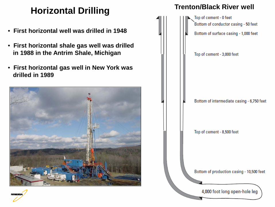
Horizontal Drilling • First horizontal well was drilled in 1948 • First horizontal shale gas well was drilled in 1988 in the Antrim Shale, Michigan
• First horizontal gas well in New York was drilled in 1989
Trenton/Black River well

Horizontal Drilling at Multi-Well Pad Sites in Black Shale
4,000 ft
3,00
0 –
8,00
0 ft
Marcellus Shale Gas Development

Orthogonal joint sets East-northeast trending J1 fractures and northwest-trending J2 fractures
Drill horizontal wells to the north-northwest or south-southeast perpendicular to major horizontal stress and J1 fractures
Dual porosity gas reservoir where fractures drain rapidly and matrix drain slowly
Connect matrix porosity to the wellbore by intersecting multiple J1 fractures
Free gas and adsorbed gas in matrix
Terry Engelder PSU

Multi-Well Drilling Pad Site With Six Horizontal Laterals
Horizontal Lateral

Multi-Well Drilling Pad Site With Six Horizontal Laterals
Horizontal Lateral
Minimizes surface disturbance but concentrates industrial activity

Directional rig for drilling horizontal leg
Top-set rig for drilling vertical surface- and intermediate-
cased interval

Walking legs on directional drilling rig
Wellheads of first two of six horizontal wells
~15 ft

Teff (2011)
Horizontal wells target basal Marcellus Shale

Target horizon (Union Springs Shale) mapped using offset well logs and seismic
Logging-while-drilling used to steer lateral within target beds
Schlumberger (2010)
Gamma
Density

Tompkins County, NY
High TOC and elevated radioactivity
in basal Marcellus Shale
Levanthal and others (1981)

Uranium & Thorium to Radium & Radon Radioactive Decay Series
Radioisotope and half life

Drill Core Sample Analysis
Lash and Engelder (2009)
Gamma Log
High TOC and abundant pyrite in basal Marcellus Shale

• Elevated uranium and abundant pyrite in high-TOC black shale • Multi-horizontal well site will generate more than 500 times the volume of shale cuttings than single-vertical well site
Drill Cuttings
Core of target interval Drill cuttings

Lined pit
Mixed with sawdust
Closed-loop system
Offsite disposal in landfill
Drilling Fluids and Cuttings

4,000 ft
3,00
0 –
8,00
0 ft
Marcellus Shale Gas Development Multi-Stage High-Volume Hydraulic Fracturing of Horizontal Laterals

3 to 5 million gallons of water for hydraulic fracturing of each horizontal lateral

Typical Components of Frac Fluid .
• For a 3 million gallon frac job, the 0.5 percent is equivalent to 15,000 gallons of “chemistry” •Re-fracing may be needed due to proppant crushing, scale, etc.

Infill Drilling Refrac
Devonenergy.com
Barnett Shale

Water Withdrawals for Frac Water
• Water-availability issues are seasonal in nature
• Withdrawal of 5 MGD during high water insignificant, during low water exceeds 10 percent of flow
• If surface water becomes more restrictive, industry will look to groundwater
• Surface-water withdrawals and municipal supply in PA
• Surface water and groundwater – a single resource
• Cumulative impacts of multiple withdrawals

Chloride (mg/L)
0
20,000
40,000
60,000
80,000
100,000
120,000
1 2 3
Total dissolved solids (mg/L)
0
50,000
100,000
150,000
200,000
250,000
1 2 3
Gross Alpha (pCi/L)
0
5000
10000
15000
20000
1 2 3
Barium (mg/L)
0
2500
5000
7500
10000
1 2 3
Water quality of flowback (1.5 million gallons) from Marcellus shale well after completion of hydraulic fracturing (Samples were taken at 1, 2, and 3 third intervals of the 2-week flowback period, PADEP)
1,160 22
19,000
668
6,100
8,730
18,600
80,500
109,000
34,600
134,000
192,000

TDS and Radioactivity of Flowback Water

Uranium & Thorium to Radium & Radon Radioactive Decay Series
Radioisotope and half life
Brine from a Marcellus Shale-Gas Well
Gross Alpha 20,800 pCi/L Gross Beta 2,390 pCi/L Radium 226 10,200 pCi/L Radium 228 1,250 pCi/L Thorium 228 47.5 pCi/L Thorium 232 0.0 pCi/L Uranium 234 0.5 pCi/L

Reuse flowback, onsite treatment for solids / blend with 70 % freshwater
Municipal wastewater treatment plants not designed to handle
flowback chemistry
Limited number of disposal
wells in Ohio
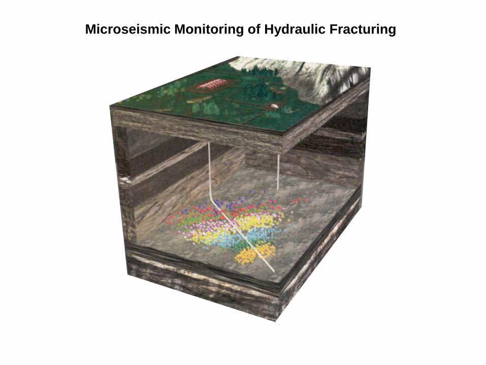
Microseismic Monitoring of Hydraulic Fracturing

•Produces readily detectable microseismic events (400 per frac) •Frac half lengths greater than 1,000 feet •Frac azimuths typically east-northeast parallel to J1 joint sets •Reactivation of pre-existing joints by strike-slip failure
Marcellus Hydraulic Fracturing
Joint sets in the Appalachian Basin Microseismic for five Marcellus laterals
Duncan and Williams-Stroud (2009)

1000
500
3500
4000
4500
5000
5500
6000 Modified from Kostelnick (2010)
Upper Hamilton Group
Stratigraphy and Frac Barriers

Marcellus shale
Onondaga limestone
Tully limestone
Upper Hamilton shale

(Marcellus SPE 131783)
Microseismic Monitoring
of Marcellus Fracs
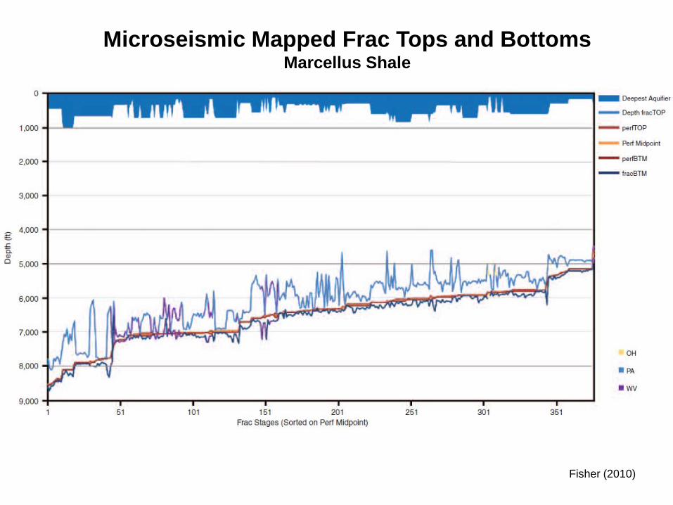
Fisher (2010)
Microseismic Mapped Frac Tops and Bottoms Marcellus Shale

Sharma and others (2003)
Fracing near faults

Trenton
Salt
Marcellus
Utica
Lockport
Onondaga
Seismic Line from South-Central New York
Smith (2010)
Tully

Teff (2011)
Avoid Structures

Valley-Fill Aquifers
Saturated deposits of glacial sand and gravel

Fractured zone in Catskill Formation
Upper Devonian Fractured-Bedrock Aquifers

Braun and others (2011)
Bedding fracture and joint in Lock Haven Formation
Upper Devonian Fractured-Bedrock Aquifers

Depth of Water Wells in USGS and NYSDEC Databases South-Central New York

Water Wells that Penetrated Saltwater in South-Central New York
Modified from Williams (2011)

Water Wells that Penetrated Saltwater in North-Central Pennsylvania
Williams and others (1998)

344 588
7,800
40
10 13
2.1 0.2
36
NS
30
3.1
Water Quality of Typical Freshwater and Salty Water Wells in Upper Devonian Bedrock
Salty water wells (Williams and others, 1998)
3
4,600
304 Tioga County, PA

Depth of Freshwater Zones Penetrated by Gas Wells South-Central New York

Modified from Williams (2011)
Wells that Penetrated Gas above the Marcellus Shale South Central New York

Freshwater and Gas in Close Vertical Proximity

Methane in Water Wells Marcellus/Utica Gas-Play Area
Osborn and others (2011)
Sampling sites

FRESH WATER AQUIFER ZONE
SHALLOW PRODUCING ZONE
INTERMEDIATE PRODUCING ZONE
CONDUCTOR PIPE
SURFACE CASING
PRODUCTION CASING
Good Zonal Isolation
TARGET PRODUCING ZONE

Poor Zonal Isolation
PRESSURE BUILDS UP
CONDUCTOR PIPE
SURFACE CASING
PRODUCTION CASING
FRESH WATER AQUIFER ZONE
SHALLOW PRODUCING ZONE
INTERMEDIATE PRODUCING ZONE
TARGET PRODUCING ZONE
CAS
ING
CEM
ENT
FOR
MAT
ION

2,500 – 4,000 feet
Characterization of deep freshwater and shallow gas and saltwater
Engineered zonal isolation by multiple casings, cement, packers, and venting
Protection of Freshwater Aquifer

Freshwater
Transition
Saltwater
Geophysical Logs and Base of Freshwater Aquifer
Log data courtesy of Shell Appalachia

• Cemented surface casing may not be deep enough to protect freshwater aquifer
• Open annulus interval between top of production casing cement to bottom of surface casing may allow upward migration of salty water and gas
• Drilling and frac fluid storage in surface impoundments and burial of drill cuttings onsite may contaminant shallow groundwater and surface water
• One-time use of frac fluid wasteful of freshwater resources and creates disposal issue
Shale Gas Development Typical past practices
- 500 feet
Top of cement 2,750 ft
• No water-well sampling before drilling/hydraulic fracturing operation

• Surface casing/cement deep enough to protect freshwater aquifers
Shale Gas Development Best practices based on state-of-the-art
technology and science
• Cement-bond logging and pressure testing to ensure good seals
• Water-well sampling before and after drilling/hydraulic fracturing operation
• Microseismic monitoring of hydraulic fracs
• Drilling and frac fluid storage in tanks and offsite burial of drill cuttings
• Reuse of frac fluid reduces freshwater resource impacts and disposal issue
• Intermediate and production casing/cement/packers to prevent upward migration of salty water and gas
• Geophysical logging to delineate base of freshwater aquifers
• Avoid hydraulic fracturing near structures
