the master 8000 - technik mfg · minnesota grandmaster 2 03/08/06 safety considerations 1. unplug...
TRANSCRIPT

THE
MINNESOTA
GRAND
MASTER
Set up and Operation Manual
Your Machine Serial Number: ________________________


THE GRANDMASTER MINNESOTA
OPERATION MANUAL
TABLE OF CONTENTS SAFETY 2 UNPACKING 2 MACHINE DIAGRAM 3 MACHINE MOUNTING 3 START-UP 4 AUTOMATIC SEQUENCING 4 SERVICE MODE 4 RUN MOTOR 4 OPERATING MODE SUMMARY 5-6 INSTALLING PUSHBUTTONS 7 COLUMN PRICING 8 RANDOM COLUMN SET UP CHART 8 CARD THICKNESS ADJUSTMENT 9 LOADING CARDS / UNLOADING CARDS 10 CHECKING CARD AND MONEY COUNT 11 NON - RESETTABLE COUNTS 11 RESETTING COUNTS 12 OPENING/CLOSING RECORDS (CASH DOOR) 12 OPENING/CLOSING RECORDS (PRODUCT DOOR) 12 POWER OFF/ON RECORDS 13 RE-INITIALIZATION PROCEDURE 13 TROUBLESHOOTING
ERROR CODES 14 - 15 ERROR CODE FLOW CHARTS 16 - 23 CARD JAM OR HESITATE 24 CARDS JAMMING FLOW CHART 24 ODD COUNTS AND DISPENSING 25 CARD NOT DISPENSING FLOW CHART 25 FUSE BLOWN 26 NO POWER 26 POWER INTERRUPTIONS 26 NO POWER FLOW CHART 27 CALLING A SERVICE TECHNICIAN 28 SERIAL NUMBER LOCATIONS 28 REGULAR MAINTENANCE (SERVICE DOOR REMOVAL) 28 CONTROL BOARD 29
BILL ACCEPTOR PROBLEMS 30 COIN MECHANISM 30 PYRAMID BILL ACCEPTOR 31 - 35 SERVICE LOG SHEET 36 ACCOUNTING SHEET 37


MINNESOTA GRANDMASTER 03/08/06 2
SAFETY CONSIDERATIONS
1. Unplug the machine when servicing – failure to do this could cause serious injury.
2. If the power cord is damaged, the manufacturer, its service agent, or a similarly qualified person must replace it.
3. Permanent bypass of any safety switches may cause serious injury. 4. Refer to the “Machine Mounting” section of the manual for proper installation
instructions. 5. A three prong grounded outlet must be used to power this machine. 6. Do not overload power circuits. 7. Do not use extension cords to run power to this machine.
UNPACKING When a machine is received, it should be carefully unpacked and checked closely for any possible damage. If a freight company is involved and there is some damage, they should be notified immediately. The machine should NOT be installed until such time as the freight company inspects it and can make out their report.
Please remove and save packing materials for later use.
The following items should be packed in the carton:
QUANTITY DESCRIPTION
1 8 -COLUMN PULL-TAB VENDING MACHINE 1 Fuse – 6 ¼ AMP 8 Short Weights 8 Three Tab Adaptors 8 Inside White Pushbutton Backs 8 Clear Pushbutton Covers 8 Pushbutton labels - $.25 8 Pushbutton labels - $.50 8 Pushbutton labels - $1.00 8 Pushbutton labels - $2.00 1 Machine Manual 4 Machine Keys - 4 for each door 1 Hex Wrench (For Adjustment Procedure) 1 Card Hook 1 Card Display Holder
1 Warranty certificate
*If the machine is equipped with a modem, an alarm, or a printer an Options Manual will be included as well.

MINNESOTA GRANDMASTER 03/08/06 3
MACHINE DIAGRAM
MACHINE MOUNTING
If machine mounting to a wall is required, there are four holes at the back of the base with 16” spacing. Lag screws and washers (not supplied) can be used to fasten the machine to a wall. If mounting to the floor is desired, holes in the base are provided, however the casters must be removed

MINNESOTA GRANDMASTER 03/08/06 4
START UP
Please be sure to check that the mechanism is free of any packing materials and that nothing interferes with its operation. Please do the same with the bill acceptor. Plug the 3-prong plug into a grounded outlet. Turn the power on with the switch that is located behind the machine. Also turn the power on with the switch provided inside the bill acceptor compartment on the control panel.
AUTOMATIC SEQUENCING
You will note that when the machine is first turned on you will hear three short audible signals, and at the same time the display on the front of the machine will show “8888” with each audible signal. The machine will then proceed to check the motors that feed the tickets and each solenoid and its corresponding pushbutton light. At the end of the sequencing, if all systems are operational, the display will read 0.00 and all eight pushbutton lights will be flashing. If the machine detects an error in the start-up process, it will display an error code. (Reference Error Codes – beginning page 18)
SERVICE MODE
The position marked 5 is used for “SERVICE”. This allows the service person to operate the machine without adding counts to the counters. An audible beep is heard approximately every 15 seconds when in the service position. If the selector switch is left in this position when the doors are closed, the machine will not record money or tickets but will dispense tickets. The control panel will not be in the normal “attract” mode with flashing lights. Return the selector switch to “VEND” position to activate the flashing lights.
RUN MOTOR
You will note on the control bar that there is a “MOTOR” position 4. This position is used in certain repair procedures for clearing jammed tickets.

MINNESOTA GRANDMASTER 03/08/06 5
OPERATING MODE SUMMARY
Vend Price Count Motor Service Cash door log Prod. Door log F log Set time Set date
Mode description
Comments Clear count ALL A B C D
This is the normal operating mode.
Following E-14, switches to sensor diagnostic display. Following E-15 clears permanent.
Toggle “ALL” mode.
Vend Product A
Vend Product B
Vend Product C
Vend Product D
Allows setting the column pricing.
. When held during power on or reset, reinitializes system memory, clears all accounting information to zero and sets all column prices to default.
Cycle column selection
Cycle price Cycle price
Cycle Price
Cycle price
Display / clear accounting information
Number displayed is number of cards dispensed for lighted column. When the ALL button is lighted, the number displayed is the total dollars accepted
Cycle column selection
Switch between resettable and non resettable counters
Motor run The feed motor runs continuously. This is used for making column feed adjustments.
Service and diagnostic mode
All normal VEND mode functions are available but accounting information (cards dispensed and dollars accepted) is not updated. Note: Credits are carried over between service and vend modes so it is important to make sure that the credits are correct before returning to vend mode. The audible alarm will sound briefly every 15 seconds.
Resets credits to zero.
Toggle “ALL” mode
Test vend product “A”
Test vend product “B”
Test vend product “C”
Test vend product “D”.
Display cash door access log.
Advance to next entry. Display Bin #
Display event start date.
Display event start time
Display event end date.
Display event end time.
Display product door log
Advance to next entry. Display Bin #
Display event start date.
Display event start time.
Display event end date.
Display event end time
Display power fail log.
Advance to next entry. Display Bin #.
Display event start date.
Display event start time.
Display event end date.
Display event end time
Display or Alter current time
Advance hours
Advance minutes
Display or alter current date
Advance month
Advance day
Display year
Advance year

MINNESOTA GRANDMASTER 03/08/06 6
Additionally, the decimal point will be on if the value displayed was altered by the time or date set function during the event. In order to make the log easier to access and interpret, the player control buttons will be used to select the values to display as follows: ALL - advance to next log entry. Display Bin #. A - display event start date. B - display event start time. C - display event end date. D - display event end time. As each value is selected, the corresponding player button will be lighted to indicate which value is being displayed.
The operating mode selector will have the following 10 positions: Vend - Normal operating mode. Price - Allows setting the column pricing. Count - Display / clear accounting information. Motor - Motor run. Service - Service and diagnostic mode. Cash door log - Display cash door log. Prod door log - Display product door log. Power fail log - Display power fail log. Set time - Display / alter current time. Set date - Display / alter current date.

MINNESOTA GRANDMASTER 03/08/06 7
INSTALLING PUSHBUTTONS
The pushbutton assembly includes the clear pushbutton cover, the denomination legend, the white plastic inside cover, and the pushbutton itself. Place the white inside cover on the machine pushbutton. Insert the denomination legend into the clear cover. Push the clear cover onto the pushbutton and push until it snaps on, one edge at a time. To remove the clear cover, use a thin screwdriver or knife blade and pry it loose between the clear cover and the outer shell.
IMPORTANT: BE SURE TO GO THROUGH THE “PRICING THE MACHINE” SECTION OF THIS MANUAL AFTER CHANGING THE CURRENCY LABELS!!!

MINNESOTA GRANDMASTER 03/08/06 8
COLUMN PRICING AND RANDOM COLUMN SETTINGS
You are now ready to set the price for each column. Minnesota rules require that tickets dispense randomly or that all tickets within the same game must dispense from at least 2 columns randomly such that the player cannot select which of the two columns. Therefore, the machine needs to be told which columns contain Game A, Game B, etc. The machine is designed to have the largest games in the left-most rows, and so on. You will notice that when you set the selector switch to position 2 – “PRICING”, that one of the digit(s) in the left column of the following table will appear:
RANDOM COLUMN / GAME SET UP CHART WHEN 8 APPEARS ON THE SCREEN, 8 ROWS WILL BE ONE RANDOM GAME (A). IN THIS CASE, YOU WILL LOAD ONLY ONE LARGE GAME INTO THE MACHINE.
WHEN 62 APPEARS ON THE SCREEN, THE LEFT 6 ROWS WILL BE ONE LARGE RANDOM GAME (A) AND THE RIGHT 2 ROWS WILL BE RANDOM GAME (B).
WHEN 44 APPEARS ON THE SCREEN, THE LEFT 4 ROWS WILL BE RANDOM GAME (A) AND THE RIGHT 4 ROWS WILL BE RANDOM GAME (B).
AND SO ON....
You change the random row settings by pushing the red “CLEAR” button on the control panel. The row buttons light up corresponding to the game chart above. Once you have decided the number of games you wish to load, you are ready to set the price of each game.
Press the “ALL” button on the game panel to price each game. The left button lights up with a new price displayed with each push. First 199 will appear then 2.00, 1.00, .75, .50, .25, then 199 again. At the desired price for the game, press the “ALL” button to price the next game...and so on... Once all of the games are priced, it is a good practice to cycle through all games by pressing the “ALL” button to visually make certain that all rows are priced correctly. Once you have priced all eight rows, return the rotary switch to the “VEND” position.
DISPLAYREADING
GAME IN COLUMN #1
GAME IN COLUMN #2
GAME IN COLUMN #3
GAME IN COLUMN #4
GAME IN COLUMN #5
GAME IN COLUMN #6
GAME IN COLUMN #7
GAME IN COLUMN #8
8 A A A A A A A A
62 A A A A A A B B
53 A A A A A B B B
44 A A A A B B B B
422 A A A A B B C C
332 A A A B B B C C
2222 A A B B C C D D

MINNESOTA GRANDMASTER 03/08/06 9
CARD THICKNESS ADJUSTMENT
FOR 20 TO 30 MIL THICK CARDS:
1. With a hex wrench, turn the adjustment screw on the dispensing mechanism counter-clockwise until it is tight enough so a card will not come out.
2. To make a “test card” place (2) pieces of clear tape or (1) piece of electrical tape as shown below.
3. Place a “test card”; tape first, in the bottom of the column you wish to adjust.
4. Place the adjustment weight on top of the card. 5. Add some money to the machine.
BEFORE GOING ANY FURTHER, PLEASE READ THE INSTRUCTIONS
BELOW
6. Place the hex wrench into the adjustment screw. 7. With the door open, dispense a card. But at the same time you are dispensing a
card, turn the adjustment screw clockwise until a card is dispensed. It may take a few tries before a card is dispensed.
8. The column is set once a card is properly dispensed. 9. For 10 mil thick cards, follow the same procedure listed above, except use (1)
piece of clear tape on the leading edge of the card.
MINNESOTA GRANDMASTER 03/08/06 10
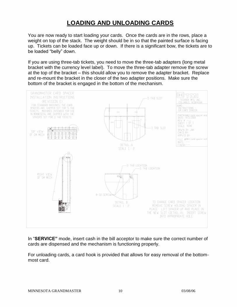
LOADING AND UNLOADING CARDS You are now ready to start loading your cards. Once the cards are in the rows, place a weight on top of the stack. The weight should be in so that the painted surface is facing up. Tickets can be loaded face up or down. If there is a significant bow, the tickets are to be loaded “belly” down. If you are using three-tab tickets, you need to move the three-tab adapters (long metal bracket with the currency level label). To move the three-tab adapter remove the screw at the top of the bracket – this should allow you to remove the adapter bracket. Replace and re-mount the bracket in the closer of the two adapter positions. Make sure the bottom of the bracket is engaged in the bottom of the mechanism. In “SERVICE” mode, insert cash in the bill acceptor to make sure the correct number of cards are dispensed and the mechanism is functioning properly. For unloading cards, a card hook is provided that allows for easy removal of the bottom-most card.

MINNESOTA GRANDMASTER 03/08/06 11
CHECKING CARD AND MONEY COUNT The Minnesota Grand Master has “resettable” and “non-resettable” accounting information. This information can be obtained with the rotary switch on the control bar. Move the rotary switch to the “COUNT” position. While the switch is on “COUNT,” all accounting information can be viewed on the display on the front of the machine.
RESETTABLE ACCOUNTING INFORMATION
While the rotary switch is in the “COUNT” position the “ALL” button will be lit. To view the ticket counts in each row press the “ALL” pushbutton. At this point, row “A” (far left pushbutton light) will be lit. The number on the display is indicating the number of tickets dispensed from that row. Press the “ALL” pushbutton once again. Now the next pushbutton (row “B”) light is lit, and the number on the display is indicating the number of tickets dispensed from that row. Continue to press the “ALL” pushbutton to view the accounting information for the remaining rows. Push the “ALL” pushbutton one more time to view the total money that the bill acceptor has received since the last time the counts were cleared. The total number of re-settable counts is 9. This includes the ticket count for each of the 8 rows, and 1 for the total dollar count when the “ALL” button is lit.
Each row can be cleared to zero by pushing the “CLEAR COUNT” button on the control bar. NOTE: All rows must be cleared individually as the accounting information is displayed. Pushing the “CLEAR COUNT” button once DOES NOT clear all of the accounting information.
NON-RESETTABLE ACCOUNTING INFORMATION
To access this information, move the rotary switch on the control bar to the “COUNT” position. The “ALL” button will be lit. Press the “ALL” pushbutton on the front button panel this will light the far left pushbutton (row “A”). Press row “A” pushbutton again. The display will now be flashing a 3-digit number, then a 4-digit number, then the 3-digit number again. The 3-digit and 4-digit numbers are combined to make a 7-digit number. See the following example:
EXAMPLE: 000, 0150, 000, 0150 ==> 0000150
To view the non-resettable ticket counts of each row, press the “ALL” pushbutton. The number on the display is indicating the number of tickets dispensed from that row. Press the “ALL” pushbutton once again. Now the next pushbutton (row “B”) light is lit, and the number on the display is indicating the number of tickets dispensed from that row. Continue to press the “ALL” pushbutton to view the accounting information for the remaining rows. Press the “ALL” pushbutton one more time to view the total money that the bill acceptor has received. After viewing the non-resettable counts, press the “ALL” pushbutton and then the far left pushbutton (row “A”) and this will return you to the resettable counts.
Return the rotary switch to “VEND” on the control panel and this will return the machine to normal operation.

MINNESOTA GRANDMASTER 03/08/06 12
RESETTING COUNTS
The procedure for resetting counts is to simply press the “CLEAR” button on the control panel as the count is displayed. This procedure has to be performed 9 times if you wish to clear all 9 counts. (All eight columns plus the ALL button)
OPENING / CLOSING RECORDS – CASH DOOR
This machine has recorded the last 25 occurrences where the cash door has been opened and closed. It records the time, date, and sequence of these events. To operate, place the selector switch to position 6, “CASH DOOR”. You will first see the number 1. This indicates that you will next see the readings for the most recent opening of the cash door. Press the far left row button on the game panel. This will display the date the cash door was last opened. Press the second button from the left to display the military time the cash door was last opened. Press the third button from the left to display the date the cash door was closed. Press the fourth button from the left to display the time the cash door as closed. Press the “ALL” button to check occurrence 2, the next most recent time the cash door was opened, etc.
OPENING / CLOSING RECORDS – PRODUCT DOOR
This machine has recorded the last 25 occurrences where the product door has been opened and closed. It records the time, date, and sequence of these events. To operate, place the selector switch to position 7” PRODUCT DOOR”. You will first see the number 1. This indicates that you will next see the readings for the most recent opening of the product door. Press the far left row button on the game panel. This will display the date the product door was last opened. Press the second button from the left to display the military time the cash door was last opened. Press the third button from the left to display the date the product door was closed. Press the fourth button from the left to display the time the product door was closed. Press the “ALL” button to check occurrence 2, the next most recent time the cash door was opened.

MINNESOTA GRANDMASTER 03/08/06 13
POWER OFF / ON RECORDS
This machine has recorded the last 25 occurrences the machine has lost and gained power. It records the time, date, and sequence of these events. To operate, place the selector switch to position 8, “POWER OUTAGE”. You will first see the number 1. This indicates that you will next see the readings for the most recent occurrence. Press the far left row button on the game panel. This will display the date the last power outage occurred. Press the second button from the left to display the military time the last power outage occurred. Press the third button from the left to display the date the power was resumed. Press the fourth button from the left to display the time that power was resumed. Press the “ALL” button to check occurrence 2, the next most recent time the power was interrupted, etc.
RE-INITIALIZATION PROCEDURE
Just as sometimes happens with any computer, its brains get scrambled. The unit has been designed for a soft landing should this occur, i.e. no major catastrophes. It has also been designed to allow for a “RE-BOOT” or “RE-INITIALIZATION. This procedure clears the program back to its initial startup when it was new. It does not erase non re-settable counter information or door closing information. It does, however, erase re-settable counts and current pricing. If possible, the re-settable counts should be recorded prior to performing this procedure. To “RE-INITIALIZE”, turn the selector switch to the “PRICE” position. Press the “CLEAR” button and hold it down. Turn the machine power off, then on again while still holding the “CLEAR” button down. Release the “CLEAR” button once the machine has proceeded through its start up cycle.

MINNESOTA GRANDMASTER 03/08/06 14
TROUBLESHOOTING
WARNING!!!! WARNING!!!! WARNING!!!! WARNING!!!! WARNING!!!!
ALWAYS UNPLUG THE MACHINE PRIOR TO SERVICING THE MACHINE
ERROR CODES The machine has the ability to determine its own reason for not functioning. It has several error codes that will tell you where the problem is occurring. The code will appear on the display, located on the cash door. The codes that may be encountered are as follows: E-02 A jumper on the board is not installed properly or the counters are not connected.
Contact a service technician for assistance. E-04 This means that a card was in the process of being dispensed when the machine
lost power. The E-04 appeared on the screen when power was restored. The machine will not function until the “CLEAR” button is pressed. When the E-04 is cleared a ticket may be dispensed. This ticket has not been recorded by the machine and should be returned to the stack. This feature is intended to prevent tampering/theft of cards. If this error code appears frequently, it is likely that someone is trying to manipulate free tickets.
E-10 This means that the machine has lost its memory, the row denominations will
default to the default pricing and the counts will be cleared. This indicates the machine needs to be re-initialized – see the “Initializing Procedure” section of this manual.
E-11 This means that the signal received from the bill acceptor took too little time. This
is a security feature. If someone had somehow found a way to send electrical signals to the circuit board to add credits to the machine, they would not know of this feature and the machine would produce either an E-11 or an E-12 error code.
E-12 This means that the signal received from the bill acceptor took too long.
This is similar to E-11 above. E-13 This means the selected ticket took too long to dispense. Remove the ticket from
that row. To clear, turn the machine off, and then back on. E-14 This means that an unexpected ticket was sensed in a row other than the
selected row. The unit will ONLY operate in the “MOTOR” mode. To clear this error code, turn the selector switch to the “MOTOR” position. This will cause the motor to run for 1.5 seconds to clear the sensed ticket. Once the sensed ticket is cleared, turn the rotary switch to the “VEND” position and turn the power off, then

MINNESOTA GRANDMASTER 03/08/06 15
on again. Repeat this procedure if the error code was not cleared on the first attempt.
** The control board is programmed with a sensor diagnostic and can be viewed
if the E-14 error codes are frequent. To enter this diagnostic, follow the procedure below:
1) With E-14 present on the display and the selector switch in the “VEND” position, push the “COUNT CLEAR” button on the control board.
2) The display will now be showing the status of the sensor for each row. To
understand this information please refer to the diagram(s) below. For the diagnostic, the display uses eight vertical bars, each bar representing the corresponding product column. Either the upper or lower half of each bar is lighted to indicate the status of the column sensor. The upper half is lighted when the sensor is unblocked. The lower half is lighted if the sensor is blocked or not installed.
3) If a row does have a faulty sensor, please contact a service technician for assistance.
4) To exit the sensor diagnostic, turn the machine off, and then back on.
8-Column machine - normal
8 Column machine - Columns A & B blocked
E-15 This means that the non re-settable counters have been corrupted due to loss of memory. It is possible to view the corrupted counters by using the procedure under E-10. While E-15 is displayed, pressing “COUNT CLEAR” will clear the error code and the machine will reset itself. NOTE: The counts on the non re-settable counters will be zero after clearing procedure. In Minnesota, regulations require that this situation be reported. Please contact Technik Mfg., Inc. for details.
E-20 This means that it took too long to dispense a ticket. See the procedure for
clearing a jam. The machine allows the player to continue play for the balance of the credits on the machine. You will note that one button lights, thereby indicating the row that did not function properly. Often the E-20 error code can be corrected by simply turning the machine off, then on again.
The game from which the E-20 malfunction occurred can be re-priced to $199 thereby not allowing play on that specific game, but allowing play of the remaining game(s).

MINNESOTA GRANDMASTER 03/08/06 16
ERROR CODES FLOW CHART
E - 0 2
E R R O R C O D E
R E S E T M A C H IN E
B Y
P R E S S IN G
" C L E A R C O U N T"
O N C O N T R O L B A R
D ID TH E
E R R O R C O D E
C L E A R ?
IF S T IL L E - 0 2 ,
B O A R D N O T
R E S P O N D IN G ,
B O A R D M A L F U N C T IO N .
iF N O M E TE R S
E N S U R E " JU M P E R "
IS P L U G G E D
T O J1 2 .
P L U G M E T E R S
TO J1 2 O N
C O N T R O L B O A R D
& R E S E T M A C H IN E
M A C H IN E W IL L
R E TU R N TO
N O R M A L
O P E R A TIO N S
N ON O
Y E S Y E S
IS T H E M A C H IN E
E Q U IP P E D W IT H
M E C H A N IC A L
M E T E R S ?

MINNESOTA GRANDMASTER 03/08/06 17
ERROR CODE FLOW CHART
E - 0 4
E R R O R C O D E
R E S E T M A C H IN E
B Y P R E S S IN G
" R E S E T " O R
T U R N IN G
P O W E R O F F / O N
D ID T H E
E R R O R C O D E
C L E A R ?
D ID E -1 5 E R R O R
C O D E A P P E A R ?
IS D IS P L A Y
IN D IC A T IN G
" 0 X .X X "
C O N TA C T A
S E R V IC E TE C H
O R C A L L
8 0 0 - 7 9 5 -8 2 5 1
S E E
IN IT IA L IZ A T IO N
P R O C E D U R E IN
O W N E R 'S
M A N U A L
P R E S S T H E
" C L E A R C O U N T "
B U T TO N O N
C O N TR O L B O A R D
O R C O N T R O L
B A R
M A C H IN E W IL L
R E T U R N TO
N O R M A L
O P E R A T IO N S
N ON ON O
Y E S Y E S Y E S

MINNESOTA GRANDMASTER 03/08/06 18
ERROR CODE FLOW CHART
E -1 0
E R R O R C O D E
R E -IN IT IA L IZ E
C O N T R O L B O A R D .
S E E IN IT IA L IZ IN G
P R O C E D U R E IN
O W N E R 'S
M A N U A L
M A C H I N E W IL L
R E T U R N T O
N O R M A L
O P E R A T IO N
P R E S S T H E
"C L E A R C O U N T "
B U T T O N .
M A C H IN E W IL L
R E T U R N T O
N O R M A L
O P E R A T IO N
C O N T R O L B O A R D
M A L F U N C T IO N .
C O N T A C T A
S E R V IC E T E C H
O R C A L L
8 0 0 -7 9 5 - 8 2 5 1
D ID T H E E R R O R
C O D E C L E A R ?
D ID E R R O R C O D E
E -0 4 A P P E A R ?
D ID E R R O R C O D E
E -1 5 A P P E A R ?
P R E S S T H E
"C L E A R C O U N T "
B U T T O N .
M A C H IN E W IL L
R E T U R N T O
N O R M A L
O P E R A T IO N
YE S
Y E S
YE S
N O
N O
N O

MINNESOTA GRANDMASTER 03/08/06 19
ERROR CODE FLOW CHART
E -1 1
E R R O R C O D E
C O N T R O L B O A R D
O R B IL L
A C C E P T O R
M A L F U N C T IO N .
C O N T A C T A
S E R V IC E
T E C H N IC IA N
O R C A L L
8 0 0 - 7 9 5 -8 2 5 1
IN T E R F A C E
W IR E H A R N E S S
D E F E C T I V E ,
C O N T A C T A
S E R V IC E
T E C H N IC IA N
O R C A L L
8 0 0 - 7 9 5 -8 2 5 1
M A C H IN E W IL L
R E T U R N T O
N O R M A L
O P E R A T IO N
D ID TH E E R R O R
C O D E C L E A R
A F TE R R E S E TT IN G
M A C H IN E ?
N O
Y E S
R E S E T M A C H IN E
B Y P R E S S IN G
" C L E A R C O U N T "
O R T U R N IN G
P O W E R O F F /O N .

MINNESOTA GRANDMASTER 03/08/06 20
ERROR CODES FLOW CHART
E -1 2
E R R O R C O D E
C O N T R O L B O A R D
O R B IL L
A C C E P T O R
M A L F U N C T IO N .
C O N T A C T A
S E R V IC E
T E C H N IC IA N
O R C A L L
8 0 0 - 7 9 5 -8 2 5 1
IN T E R F A C E
W IR E H A R N E S S
D E F E C T I V E ,
C O N T A C T A
S E R V IC E
T E C H N IC IA N
O R C A L L
8 0 0 - 7 9 5 -8 2 5 1
M A C H IN E W IL L
R E T U R N T O
N O R M A L
O P E R A T IO N
D ID TH E E R R O R
C O D E C L E A R
A F TE R R E S E TT IN G
M A C H IN E ?
N O
Y E S
R E S E T M A C H IN E
B Y P R E S S IN G
" C L E A R C O U N T "
O R T U R N IN G
P O W E R O F F /O N .

MINNESOTA GRANDMASTER 03/08/06 21
ERROR CODES FLOW CHART
E -1 3
E R R O R C O D E
S E E " C A R D
A D JU S TM E N T"
P R O C E D U R E
IN O W N E R 'S
M A N U A L
C L E A N A N D
C H E C K F O R
W E A R O N
B E L TS , A N D
O -R IN G S
C O N TA C T A
S E R V IC E
T E C H N IC IA N
O R C A L L
8 0 0 - 7 9 5 -8 2 5 1
R E -A L I G N
D E S P E N S IN G
M E C H TO C L E A R
O B S T R U C TIO N
C L E A R
O B S T R U C TIO N
A N D TE S T
D IS P E N S IN G
O P E R A TIO N
IS C A R D
TH IC K N E S S
A D JU S TM E N T
C O R R E C T?
D O E S TH E C A R D
C O N TA C T A N
O B S TR U C TIO N W H E N
D E S P E N S E D ?
IS TH E C A R D P A T H
O B S TR U C TE D ?
N O
YE SY E S
N O N O
Y E S

MINNESOTA GRANDMASTER 03/08/06 22
ERROR CODES FLOW CHART
E - 1 4
E R R O R C O D E
P R E S S TH E
" R E S E T"
B U TT O N O N TH E
C O N T R O L B O A R D
O R TU R N T H E
M A C H IN E
O FF / O N
M A C H IN E W IL L
R E T U R N TO
N O R M A L
O P E R A TIO N S
C H E C K C A R D
P A TH / S E N S O R S
F O R
O B S T R U C TIO N S
C H E C K F O R
L O O S E O R
D A M A G E D
W IR E S O N
S E N S O R
C O N N E C TIO N S
C O N S U L T
O W N E R 'S
M A N U A L FO R
S E N S O R
D IA G N O S TIC T O
D E TE R M IN E
FA U L TY S E N S O R
D ID TH E
E R R O R C O D E
C L E A R ?
Y E S
N O

MINNESOTA GRANDMASTER 03/08/06 23
ERROR CODES FLOW CHART
E -1 5
E R R O R C O D E
M A C H IN E W IL L
R E T U R N T O
N O R M A L
O P E R A T IO N S
C O N T R O L B O A R D
M A L FU N C T IO N .
C O N T A C T A
S E R V IC E
T E C H N IC IA N
O R C A L L
8 0 0 -7 9 5 - 8 2 5 1
D ID T H E E R R O R
C O D E C L E A R ?
Y E S
N O
P R E S S TH E
" C L E A R C O U N T "
B U TT O N O N
C O N T R O L B O A R D
O R C O N T R O L
B A R

MINNESOTA GRANDMASTER 03/08/06 24
CARDS JAM OR HESITATE
1) Cards may be too thick or thin. Or the card gap may need to be adjusted. See “Card Thickness Adjustment” 2) Cards may be excessively warped or bowed. Call your supplier. 3) Cards may be glued together. The machine is designed not to accept 2 cards at once. Again, call your supplier. Also, fanning the cards prior to loading may solve this problem. 4) Cards may be damaged. Remove damaged cards and try again. 5) A loose roller may cause this problem. A loose setscrew that is intended to lock the rollers to the shaft can cause this.
CARDS JAMMING OR HESITATING FLOW CHART
C A R D S JA M M IN G
O R H E S IT A T IN G
S E E C A R D
A D JU S TM E N T
P R O C E D U R E IN
O W N E R 'S
M A N U A L
R E A L IG N O R C L E A R
O B S TR U C TIO N
A N D TE S T
D IS P E N S IN G
O P E R A TIO N
C O N TA C T A
S E R V IC E
TE C H N IC IA N
O R C A L L
8 0 0 - 7 9 5 -8 2 5 1
C L E A N B E L T S ,
O - R IN G S . C H E C K
FO R W E A R O N
B E L T S , O R IN G S .
IS TH E W E IG H T
O N TH E S T A C K
O F C A R D S ?
IS T H E
C A R D T H IC K N E S S
A D J U S TM E N T
C O R R E C T?
N O
Y E S
N O
YE S
Y E S
N OD O E S T H E C A R D
C O N TA C T A N
O B S TR U C TIO N
W H E N
D IS P E N S E D ?
A D D W E IG H T

MINNESOTA GRANDMASTER 03/08/06 25
ODD COUNTS AND DISPENSING
1) Static electricity is a major contributor to this and all other electronic equipment. You MUST use a 3-prong grounded receptacle. 2) At times (mostly in the winter), strange static problems can occur. It may be necessary to spray the carpet area around the machine with a diluted mixture (10:1) of Downy fabric softener and water once every two weeks. DO NOT SPRAY MACHINE. 3) Total re-programming may be needed. See the “INITIALIZING PROCEDURE”. This procedure erases all settings and re-settable counts. The machine must now be re-programmed. 4) Low voltage causes many electronic problems. If your unit is plugged into an extension cord, or is on the same line with refrigeration equipment, etc., the 115-volt supply may be less than 100 volts. Have an electrician check the voltage supplied to the machine and repair as needed. 5) The sensor may be dirty. One sensor is built into each track just beyond the drive rollers. Should the lower sensor get filled with card shavings, it may not be able to sense. Simply blow air or use a cotton swab to clean this area.
CARDS NOT DISPENSING
N O T
D IS P E N S IN G
A N Y C A R D S
S E E IN IT IA L IZA T IO N
P R O C E D U R E IN
O W N E R 'S M A N U A L
C O N TA C T A S E R V IC E
TE C H O R C A L L
8 0 0 -7 9 5 -8 2 5 1
" S E E " E R R O R C O D E S " IN
O W N E R 'S M A N U A L . A
S E N S O R D IA G N O S TIC IS
A V A IL A B L E
S E E C A R D
A D JU S T M E N T
P R O C E D U R E IN
O W N E R 'S M A N U A L
M O TO R A N D / O R
S O L E N O ID N O T
FU N C TIO N IN G . C O N TR O L
B O A R D M A L F U N C TIO N
P H YS IC A L L Y , M O TO R
O R S O L E N O ID N O T
A B L E TO FU N C T IO N .
C H E C K M A N U A L L Y
C H E C K P U S H B U TT O N ,
S W ITC H F U N C TIO N .
C H E C K W IR IN G
H A R N E S S FO R L O O S E
O R M IS S IN G
C O N N E C T IO N S
C O N T R O L B O A R D N O T
R E S P O N D IN G TO
P U S H B U TT O N
S W ITC H E S -> C O N T R O L
B O A R D M A L FU N C T IO N
W H IL E IN
" S E R V IC E " D O E S
IT E -1 4 C O D E ?
IS TH E
C O N TR O L B O A R D
IN IT IA L IZ E D
C O R R E C TL Y ?
W H E N S E L E C TE D ,
D O E S TH E
C O L U M N A T TE M P T
TO D IS P E N S E ?
Y E S
N O N ON O
Y E S Y E S
D O E S TH E
C O L U M N
R E S E T ?
Y E S
N O

MINNESOTA GRANDMASTER 03/08/06 26
FUSE BLOWN
If the machine shuts down and nothing works, check the fuse. The machine uses a 6 ¼ AMP fuse.
NO POWER Please be aware of the POWER ON switch on the backside of the steel cabinet. This switch is available for resetting certain functions on the machine without the need of opening the door and using the control panel switch.
POWER INTERRUPTIONS
It is possible that if power dies exactly at the moment a card is being delivered, the card will stop and not be delivered until power is returned and the motor is ran. The machine recognizes this situation by displaying an E-04 error code. The machine will not operate until reset. This single ticket that was dispensed will not have been counted, nor will it have been deducted from the credit. Two possibilities then exist: 1) The customer removes and plays the ticket after power has been restored. This is not a problem since the ticket has been paid for. The person at the location realizes this is due to the E-04 error code and dispenses one additional ticket from that column and returns it to the stack. This procedure corrects the ticket count and the dollar count. 2) The person at the location can simply return the ticket to the stack after it has been dispensed and allow the customer to play. This procedure also corrects the card and money count.

MINNESOTA GRANDMASTER 03/08/06 27
NO POWER FLOW CHART
N O P O W E R
P L U G
M A C H IN E IN
T U R N P O W E R
S W I T C H O N
R E P L A C E T H E
F U S E W IT H
P R O P E R
A M P E R E
R A T IN G
C H E C K B U L B
& C IR C U IT
B R E A K E R F O R
M A C H IN E
P O W E R
C O N T A C T A
S E R V IC E
TE C H N IC IA N
O R C A L L
8 0 0 - 7 9 5 -8 2 5 1
P O W E R S U P P L Y
O R C O N T R O L
B O A R D
D E FE C T IV E .
IS M A C H IN E
P L U G G E D IN ?
IS P O W E R
S W IT C H
T U R N E D O N ?
IS T H E F U S E
O K A Y ?
N O
N O
N O
N O
Y E S
Y E S
Y E S
YE S
D O E S T H E
F L O U R E S C E N T
L IG H T C O M E
O N ?

MINNESOTA GRANDMASTER 03/08/06 28
CALLING A SERVICE TECHNICIAN
Service is available at your fingertips. Simply call the number shown on the front of this book or on the label placed inside the machine.
When calling for service, PLEASE HAVE MACHINE SERIAL NUMBER READY.
SERIAL NUMBER LOCATIONS
The serial numbers are located on the inside of the main ticket door below the window, in the bill acceptor compartment on the right wall and on the front of this manual.
REGULAR MAINTENANCE This machine requires very little regular maintenance. The bearings and the wear elements are designed for long life. However, it is recommended that the following be performed on a regular basis:
* Blow air in the front of the mechanism onto the sensors to eliminate paper dust from covering the sensor.
* Clean the exterior of the machine with a moist soft cloth and a window cleaning solution. The front glass is made of polycarbonate, which is bullet proof, but it is prone to scratching when rubbed with a dry cloth or rag.

MINNESOTA GRANDMASTER 03/08/06 29
CONTROL BOARD

MINNESOTA GRANDMASTER 03/08/06 30
BILL ACCEPTOR PROBLEMS
IMPORTANT: DO NOT DISMANTLE THE BILL ACCEPTOR and attempt to repair
the internal mechanism. This will void the warranty, and there will be charges for repairs.
COIN MECHANISM (OPTIONAL)
If your dispensing machine is equipped with a coin mechanism, it is designed to work with QUARTERS ONLY and other currency should not be tried in it. The coin mechanism is mounted to the faceplate with 4 small carriage bolts. If it is necessary to remove it, the nuts to these are removed with a 6mm nut driver or socket from the rear of the machine. The electrical connections are 2 spade lugs at the rear of the mechanism. ONLY THE TOP 2 LUGS are used, the bottom terminal is not connected. In the event of a jam that the release lever in front won’t clear, open the bill acceptor door of the machine and turn the power to the machine off. Next, locate the cylindrical spring at the top of the mechanism and slide it toward you until it is only on about 1/2 inch. As you look at the right side of the mechanism, you will see a metal collar with a screw rising from it. Grasp this with your thumb and forefinger and remove the right side of the mechanism. At this point, the coins that are stuck will be exposed and should be gently removed with the use of a toothpick or other slim object. Near the rear of the mechanism on the left, there is a brightly polished metal plate on a pivot. Immediately above this plate is a slot going into the mechanism. With a toothpick or other slim (not sharp) object, clear this area of any coins or foreign matter that may be stuck there. Re-assemble mechanism by returning the side of the mechanism to its former position and sliding the cylindrical spring away from you until it is firmly holding the side plate to the rest of the mechanism. If the mechanism fails to give credit for quarters inserted, check to see that both of the top 2 terminals are connected to the wiring harness. If they are, it will be necessary to adjust the bend on the trip wire located at the bottom rear of the mechanism. With a pair of needle nose pliers, just bend the wire a little more sharply at the same place it is already bent. This should cure the problem.

MINNESOTA GRANDMASTER 03/08/06 31
PYRAMID BILL ACCPETOR
Acceptor Diagnostics Use the Diagnostic Pushbutton on the side of the acceptor (toward the rear) as shown.
Diagnostic Push Button Flash Memory Connector
MINNESOTA GRANDMASTER 03/08/06 32
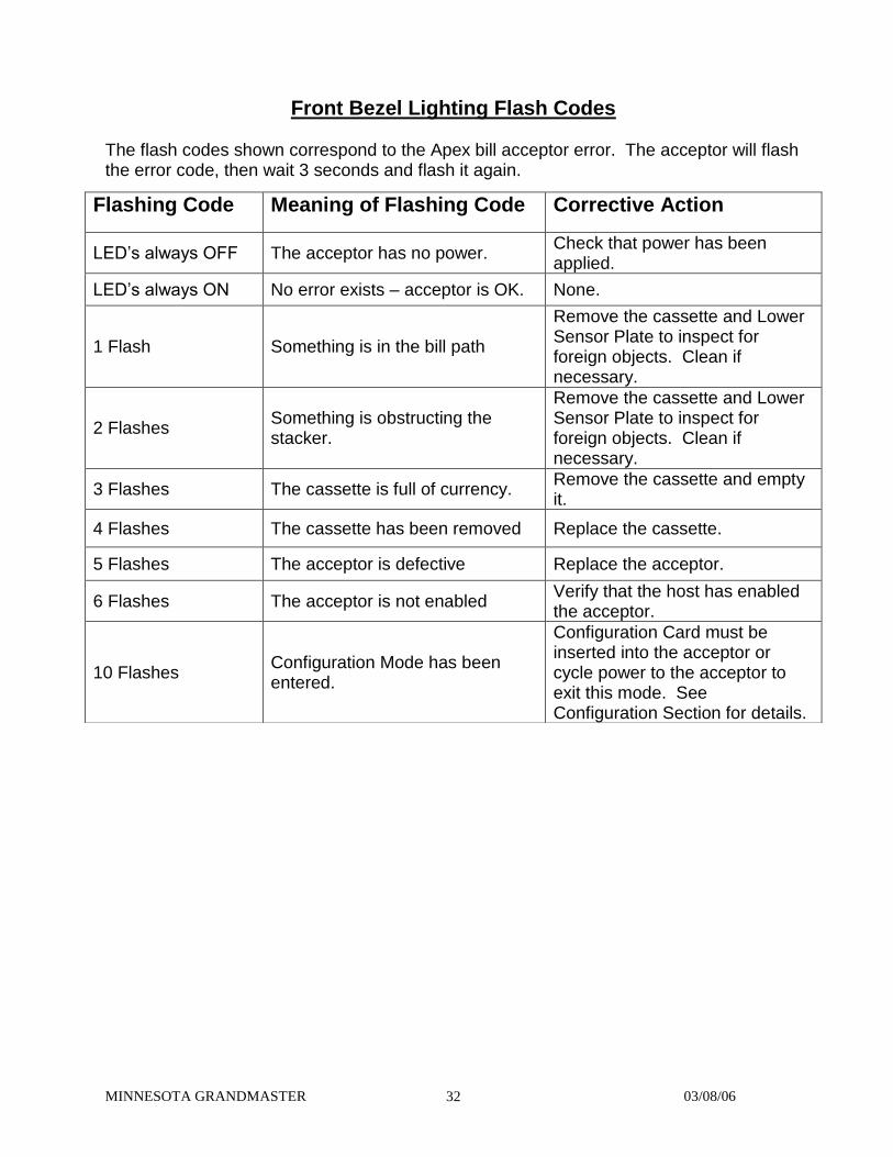
Front Bezel Lighting Flash Codes
The flash codes shown correspond to the Apex bill acceptor error. The acceptor will flash the error code, then wait 3 seconds and flash it again.
Flashing Code Meaning of Flashing Code Corrective Action
LED’s always OFF The acceptor has no power. Check that power has been applied.
LED’s always ON No error exists – acceptor is OK. None.
1 Flash Something is in the bill path
Remove the cassette and Lower Sensor Plate to inspect for foreign objects. Clean if necessary.
2 Flashes Something is obstructing the stacker.
Remove the cassette and Lower Sensor Plate to inspect for foreign objects. Clean if necessary.
3 Flashes The cassette is full of currency. Remove the cassette and empty it.
4 Flashes The cassette has been removed Replace the cassette.
5 Flashes The acceptor is defective Replace the acceptor.
6 Flashes The acceptor is not enabled Verify that the host has enabled the acceptor.
10 Flashes Configuration Mode has been entered.
Configuration Card must be inserted into the acceptor or cycle power to the acceptor to exit this mode. See Configuration Section for details.

MINNESOTA GRANDMASTER 03/08/06 33
Removing the Cashbox To remove the stacker, push back the Cashbox Latch toward the front of the acceptor. Then pull the Cashbox upward, and then pull back to remove.
Cashbox Latch
Main Housing Cashbox

MINNESOTA GRANDMASTER 03/08/06 34
Installing the Cashbox
Cashbox
Main Housing
NOTE: WHEN INSTALLING THE CASHBOX MAKE SURE THE TABS ARE PUSHED FORWARD INTO THE SLOTS ON THE MAIN HOUSING AND THEN PUSH DOWN MAKING SURE THEY CLICK INTO PLACE. IF THE CASHBOX IS NOT PROPERLY INSTALLED THE BILL ACCEPTOR WILL NOT FUNCTION.

MINNESOTA GRANDMASTER 03/08/06 35
Removal of the Lower Sensor Plate Removal of the Lower Sensor Plate is done by pressing the locking tab in and pulling the plate back. NOTE: Before removing the Lower Sensor Plate make sure you unplug the 18 pin connector from the other side of the bill acceptor. It is not shown in the picture. Main Housing Locking Tab Lower Sensor Plate Lower Sensor Plate

MINNESOTA GRANDMASTER 03/08/06 36
TECHNIK MFG., INC. 1005 - 17th STREET
P.O. BOX 1617 COLUMBUS, NE 68602-1617
1-800-795-8251
SERVICE LOG SHEET
MACHINE SERIAL NUMBER___________________DATE INSTALLED___________ MACHINE MODEL TYPE________________________ INSTALLED BY___________ BUSINESS LOCATION NAME____________________________________________ BUSINESS ADDRESS__________________________________________________ CITY/STATE/ZIP________________________________________________________
DATE SERVICE PERFORMED SERVICED BY


MINNESOTA GRANDMASTER 03/08/06 37
MINNESOTA GRAND MASTER MACHINE LOG SHEET
DATE MACHINE ROW CARD VALUE TOTAL CARDS TOTAL CASH ________ _____________ ____________ _____________ ____________ ________ _____________ ____________ _____________ ____________ ________ _____________ ____________ _____________ ____________ ________ _____________ ____________ _____________ ____________ ________ _____________ ____________ _____________ ____________ ________ _____________ ____________ _____________ ____________ ________ _____________ ____________ _____________ ____________ ________ _____________ ____________ _____________ ____________ ________ _____________ ____________ _____________ ____________ ________ _____________ ____________ _____________ ____________ ________ _____________ ____________ _____________ ____________ ________ _____________ ____________ _____________ ____________ ________ _____________ ____________ _____________ ____________ ________ _____________ ____________ _____________ ____________ ________ _____________ ____________ _____________ ____________ ________ _____________ ____________ _____________ ____________ ________ _____________ ____________ _____________ ____________ ________ _____________ ____________ _____________ ____________ ________ _____________ ____________ _____________ ____________ ________ _____________ ____________ _____________ ____________ ________ _____________ ____________ _____________ ____________ ________ _____________ ____________ _____________ ____________