the mercury laser altimeter instrument for the messenger
TRANSCRIPT

Space Sci Rev (2007) 131: 451–479DOI 10.1007/s11214-007-9273-4
The Mercury Laser Altimeter Instrumentfor the MESSENGER Mission
John F. Cavanaugh · James C. Smith · Xiaoli Sun · Arlin E. Bartels ·Luis Ramos-Izquierdo · Danny J. Krebs · Jan F. McGarry · Raymond Trunzo ·Anne Marie Novo-Gradac · Jamie L. Britt · Jerry Karsh · Richard B. Katz ·Alan T. Lukemire · Richard Szymkiewicz · Daniel L. Berry · Joseph P. Swinski ·Gregory A. Neumann · Maria T. Zuber · David E. Smith
Received: 28 August 2006 / Accepted: 24 August 2007 / Published online: 9 November 2007© Springer Science+Business Media B.V. 2007
Abstract The Mercury Laser Altimeter (MLA) is one of the payload science instrumentson the MErcury Surface, Space ENvironment, GEochemistry, and Ranging (MESSENGER)mission, which launched on August 3, 2004. The altimeter will measure the round-trip timeof flight of transmitted laser pulses reflected from the surface of the planet that, in combi-nation with the spacecraft orbit position and pointing data, gives a high-precision measure-ment of surface topography referenced to Mercury’s center of mass. MLA will sample theplanet’s surface to within a 1-m range error when the line-of-sight range to Mercury is lessthan 1,200 km under spacecraft nadir pointing or the slant range is less than 800 km. Thealtimeter measurements will be used to determine the planet’s forced physical librations bytracking the motion of large-scale topographic features as a function of time. MLA’s laserpulse energy monitor and the echo pulse energy estimate will provide an active measurementof the surface reflectivity at 1,064 nm. This paper describes the instrument design, prelaunchtesting, calibration, and results of postlaunch testing.
Keywords Mercury · MESSENGER · Topography · Laser altimeter
J.F. Cavanaugh (�) · J.C. Smith · X. Sun · A.E. Bartels · L. Ramos-Izquierdo · D.J. Krebs ·J. McGarry · A.M. Novo-Gradac · J.L. Britt · J. Karsh · R.B. Katz · D.L. Berry · J.P. Swinski ·G.A. Neumann · D.E. SmithNASA Goddard Space Flight Center, Greenbelt, MD 20771, USAe-mail: [email protected]
R. TrunzoSwales Aerospace, Beltsville, MD 20705, USA
R. SzymkiewiczOrbital Sciences, Greenbelt, MD 20770, USA
A.T. LukemireSpace Power Electronics, Kathleen, GA 31047, USA
M.T. ZuberMassachusetts Institute of Technology, Cambridge, MA 02129, USA

452 J.F. Cavanaugh et al.
1 Introduction
1.1 Mission Overview
The Mercury Laser Altimeter (MLA) is one of seven scientific instruments on the MEr-cury Surface, Space ENvironment, GEochemistry, and Ranging (MESSENGER) spacecraft.MESSENGER was launched on August 3, 2004, and will enter Mercury orbit in 2011 toperform scientific measurements for a period of one Earth year, equivalent to four Mercuryyears. MESSENGER will be in a highly elliptical and near-polar orbit around Mercury witha periapsis altitude of 200 to 400 km, an apoapsis altitude of ∼15,000 km, and a period of12 hours. Figure 1 shows the MESSENGER orbits and MLA measurement geometry. Thespacecraft altitude will come within the MLA ranging capability near periapsis for 15 to45 minutes during each orbit, depending on the time of the year. The periapsis latitude is at60–70°N to increase the measurement coverage for low-latitude regions. The intense heatfrom the Sun will require the spacecraft to have its sunshade facing the Sun at all times,which during noon–midnight orbits will confine the payload deck to point within 10° aboutthe normal to Mercury’s orbital plane with MLA ranging at a slant angle as high as 50°(Solomon et al. 2001).
1.2 MLA Instrument Overview
MLA is a time-of-flight laser rangefinder that uses direct pulse detection and pulse edgetiming to determine range to the surface. Its laser transmitter emits 5-ns pulses at an 8-Hzrate with 20 mJ of energy at a wavelength of 1,064 nm. Return echoes are collected by an
Fig. 1 MESSENGER spacecraft orbit around Mercury. MLA will measure range to the surface when thespacecraft is less than 800 km from the surface and the instrument’s optical axis is within 50° of nadir. Foroptical axis angles approaching 0° (nadir pointing) MLA can range to the surface from 1,200 km

The Mercury Laser Altimeter Instrument for MESSENGER 453
Fig. 2 MLA instrument shownwithout thermal protectionblankets
array of four refractive telescopes and detected using a single silicon avalanche photodiodeand three matched low-pass electronic filters. Pulse timing is measured using a combinationof crystal-oscillator-based counters and high-resolution time-of-flight application-specificintegrated circuits (ASICs). The MLA instrument is shown in Fig. 2.
2 Science and Measurement Objectives
2.1 MLA Science Objectives
The primary science measurement objectives for MLA are to provide a high-precision topo-graphic map of the high northern latitude regions; to measure the long-wavelength topo-graphic features at mid-to-low northern latitudes; to determine topographic profiles acrossmajor geologic features in the northern hemisphere; and to detect and quantify the planet’sforced physical librations by tracking the motion of large-scale topographic features as afunction of time. An additional goal of the MLA instrument is to measure the surface reflec-tivity of Mercury at the MLA operating wavelength of 1,064 nm (Sun et al. 2004).
2.2 MLA Instrument Objectives
MLA will measure the topography of the Mercury northern hemisphere via laser pulse time-of-flight data and spacecraft orbit position data in an approach similar to the Mars OrbiterLaser Altimeter (MOLA) (Abshire et al. 2000). MLA is designed to perform range timingmeasurements up to 1,800 km from the planet’s surface. Since the single-pulse signal linkmargin is close to 0 dB for altitudes above 800 km, the MLA data acquisition scheme allowscollection and downlink of up to 15 returns per shot in order to allow the use of correlationtechniques to process the range signals on the ground. Measurement of both the outgoingpulse energy and received pulse shape enable the surface reflectivity measurement. TheMLA functional requirements are enumerated in Table 1; allocations and constraints arelisted in Table 2.

454 J.F. Cavanaugh et al.
Table 1 Summary of MLA functional requirements
Time-stamp laser pulses to better than ±1 ms with respect to the ephemeris
Support determination of pointing stability to ±50 μrad peak-to-peak
Measure laser pulse time of flight from 1 to 8 ms with return pulse widths from 6 to 1,000 ns
Total ranging error <1 m with probability of detection Pd > 95% at 200 km altitude nadir pointing
Laser pulse repetition rate of 8 Hz
Produce laser footprint ≤16 m diameter at 200 km altitude, nadir pointing
Pd > 10% at 800 km slant range and 50° angle
Maintain long-term ranging bias error to ≤0.50 m over the mission lifetime
Measure the reflectivity of the ranging targets
Table 2 MLA design allocations and constraints
Parameter Requirement
Instrumentdesign life
6.6-year cruise with power off, followed by 1 year of operation
Orbitdefinition
Periapsis altitude = 200 km, apoapsis altitude = 15,193 km, inclination = 80°, latitudeof periapsis ≤60°, period = 12 hours
Flightenvironment
Infrared irradiance from Mercury not to exceed 1 W/cm2 onto the instrument fora 60 minute pass centered about periapsis; cold space viewing for the remaining 11 hoursof the orbit
Testingenvironment
Protoflight verification program per MESSENGER Component EnvironmentalSpecification, drawing #7384-9101
Mass 7.4 kg
Power <25 W for 60 minutes centered on periapsis and <16 W for the remaining 11 hours ofthe orbit. <17 W orbit average
Telemetry 2.0 Mbit average per 12-hour orbit about Mercury
Timecorrelation
1 pulse per second time tick from the spacecraft along with announcement with <50 msaccuracy in real time and <1 ms following navigation data processing
Relativepointing
Determine laser output pointing direction with respect to the spacecraft axes overtemperature to ±50 μrad peak to peak
Envelope 28 cm × 28 cm × 26 cm
3 MLA Instrument Design
3.1 Background
MLA builds on the experiences gained from the development of several space-based andairborne laser altimeter systems flown over the past two decades including the Mars Ob-server Laser Altimeter (MOLA-1; Zuber et al. 1992), the Mars Orbiter Laser Altimeter(MOLA-2; Smith et al. 1998), two Shuttle Laser Altimeters (SLA-1 and SLA-2; Garvinet al. 1998), the Geoscience Laser Altimeter System on the Ice Cloud and Land ElevationSatellite (GLAS/ICESAT; Zwally et al. 2002), and the airborne Microchip Laser AltimeterSystem Microaltimeter (Degnan 2002). The measurement scheme for MLA is similar to thatof MOLA, in which the outgoing pulse starts a counter that is stopped by the detection of

The Mercury Laser Altimeter Instrument for MESSENGER 455
a received echo pulse. A significant change implemented in MLA is the ability to recordseveral return pulses, process them onboard, and send the “most likely” signal returns to theground for correlation analysis. This technique is similar to and derived from experiencewith the Microaltimeter (Degnan 2002).
3.2 MLA Functional Overview
An overview of MLA operation may be gained from the MLA functional block diagram(Fig. 3). A trigger pulse initiated by the range measurement electronics starts the opticalpumping of the MLA laser. This trigger pulse also initiates a 5-MHz 23-bit counter, 16 bits ofwhich are used for coarse range timing. After optically pumping the laser for approximately150 μs the laser emits a 5-ns, 20-mJ pulse, which propagates along the instrument line-of-sight to the planet’s surface. A small fraction (<10−6) of the emitted pulse impinges on afour-segment photodiode that performs three functions. One output of this photodiode isfed to the laser electronics where it is used to terminate the laser diode pump array drivecurrent. The second output goes to a pulse integrator used to measure emitted energy, anda third output is fed to a comparator, which generates a logic pulse synchronous with thetransmitted optical pulse. The leading edge of this latter pulse starts the first of six fine-resolution time-of-flight counters, which is subsequently stopped by the next edge of the5-MHz clock. These counters provide a relative time within each 200-ns coarse clock cycle.The coarse counter value is latched at this point, and the two counters provide the leading-edge start timing value (with respect to the trigger pulse) for the range measurement. Thetrailing edge of the start pulse is timed in an identical manner. These first pair of countsestablish the start time of the range timing cycle. The pulse width is computed by subtractingthe leading edge measurement from the trailing edge measurement.
A portion of the pulse energy reflected off the planet’s surface is collected by MLA’s fourreceiver telescopes and focused onto four optical fibers that relay the signal through an opti-
Fig. 3 MLA functional block diagram

456 J.F. Cavanaugh et al.
cal bandpass filter to a silicon avalanche photodiode (SiAPD), which preserves to the extentof its bandwidth the deformation of the incident pulse caused by interaction with surfacefeatures. Slant angle ranging, surface roughness, or large-scale features on the surface cancause temporal pulse spreading. To maximize the probability of detecting spread returns,three matched filters are used after the detector amplifier. The first, a high-bandwidth filteroutput with a 10-ns impulse response, is split and fed to two comparators with independentlyprogrammable thresholds referred to as channel 1 high and low, respectively. The channel 1high comparator signal is fed to the second pair of time-of-flight counters, which record theleading and trailing edge times of this pulse. The channel 1 low comparator and the otherfilter outputs with 60-ns and 270-ns impulse response, referred to as channels 2 and 3, re-spectively, are fed to the third pair of counters. For this last pair of counters the first receivedpulse leading edge to cross its corresponding threshold will stop the counter and lock out theother channels for approximately 1 μs in order to prevent a different channel from stoppingthe trailing edge counter. The MLA Range Measurement Unit (RMU) can collect and storeup to 15 signal pulse returns from this last set of counters.
The nominal operational timebase for MLA event sequencing and range measurement isthe MESSENGER spacecraft’s oven-controlled crystal oscillator. The 5-MHz signal fromeither of the spacecraft’s redundant oscillators can be used. The laser trigger operating at8 Hz is also synchronized to the spacecraft 1-pulse-per-second (1-PPS) timing reference.A third backup 5-MHz crystal oscillator on the MLA RMU board can also be used.
To maximize the probability of return signal detection in MESSENGER’s dynamic oper-ating environment, MLA uses a real-time embedded algorithm to monitor background noiseand adjust comparator threshold levels to minimize false signals. The MESSENGER space-craft also provides MLA with once-per-second updates of estimated line-of-sight range toMercury based on spacecraft attitude and orbit data. This information is used to dynamicallyset the range-gate time delays and gain levels for the detector amplifier.
For altitudes greater than 800 km on the inbound and outbound orbit trajectories theMLA signal-to-noise ratio becomes sufficiently weak that the “high” threshold channel is nolonger detecting the return. In this situation the software collects and downlinks the multiplereturn pulses from the “low” channel timers.
The signal-tracking algorithm and the MLA command and data-handling software areimplemented on a radiation-hardened 80C196 processor that, with a control and data com-munications field-programmable gate array (FPGA) and memory devices, make up thecentral-processing unit (CPU) electronics board. The RMU board is housed with this boardin a box underneath the main instrument housing (shown in Fig. 2). The detector, amplifiers,and comparators are mounted on a separate printed wiring board and mechanically mated tothe aft optics, which filter and focus the signal from the receiver fiber optics.
Housekeeping signal conditioning and data conversion functions are performed on an-other circuit board referred to as the Analog Electronics Module (AEM). Laser control anddrive functions are implemented on two assemblies beneath the laser bench referred to as theLaser Electronics Assembly (LEA). All of the secondary voltages are converted in the PowerConverter Assembly (PCA) located in the magnesium box bolted directly to the spacecraftdeck adjacent to the main MLA housing.
Command and data communications to the MESSENGER payload Data Processing Unit(DPU) are through a low-voltage differential signal (LVDS) serial link using the RS-422signal standard. An additional LVDS signal carrying the 5-MHz spacecraft reference clockis also provided to MLA and connects directly to the RMU board. The MLA instrument hassingle-string components but can operate from either one of the redundant DPU, clock, andpower connections.
The Mercury Laser Altimeter Instrument for MESSENGER 457
MLA has two defined software modes, Boot and Application. Boot mode is entered im-mediately after power up. MLA will remain in Boot mode until commanded to execute itsonboard code residing in electrically erasable programmable read-only memory (EEPROM),at which point it enters Application mode. Within Application mode there are three definedoperational modes through which MLA will cycle every orbit. The lowest power mode isKeep Alive, in which only the CPU, AEM, and laser diode’s thermo-electric cooler (TEC)are powered. Upon transition to Standby mode the RMU is powered on. Finally, in Sciencemode, the laser power supply is turned on and the laser fires.
3.3 Technology Advances Implemented in MLA
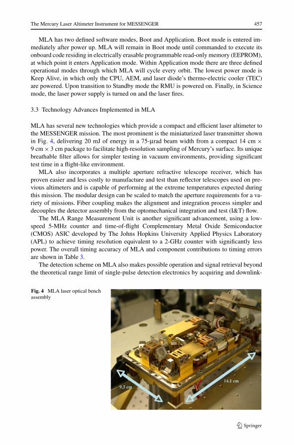
MLA has several new technologies which provide a compact and efficient laser altimeter tothe MESSENGER mission. The most prominent is the miniaturized laser transmitter shownin Fig. 4, delivering 20 mJ of energy in a 75-μrad beam width from a compact 14 cm ×9 cm × 3 cm package to facilitate high-resolution sampling of Mercury’s surface. Its uniquebreathable filter allows for simpler testing in vacuum environments, providing significanttest time in a flight-like environment.
MLA also incorporates a multiple aperture refractive telescope receiver, which hasproven easier and less costly to manufacture and test than reflector telescopes used on pre-vious altimeters and is capable of performing at the extreme temperatures expected duringthis mission. The modular design can be scaled to match the aperture requirements for a va-riety of missions. Fiber coupling makes the alignment and integration process simpler anddecouples the detector assembly from the optomechanical integration and test (I&T) flow.
The MLA Range Measurement Unit is another significant advancement, using a low-speed 5-MHz counter and time-of-flight Complementary Metal Oxide Semiconductor(CMOS) ASIC developed by The Johns Hopkins University Applied Physics Laboratory(APL) to achieve timing resolution equivalent to a 2-GHz counter with significantly lesspower. The overall timing accuracy of MLA and component contributions to timing errorsare shown in Table 3.
The detection scheme on MLA also makes possible operation and signal retrieval beyondthe theoretical range limit of single-pulse detection electronics by acquiring and downlink-
Fig. 4 MLA laser optical benchassembly

458 J.F. Cavanaugh et al.
Table 3 Componentcontributions to MLA range error Error source Contribution
Leading edge timing 0.06 m
Clock frequency error (0.1 parts per million) 0.20 m
Measurement quantization (2.5 ns) 0.11 m
Pointing angle uncertainty (0.13 mrad) 0.68 m
Spacecraft orbit knowledge error 0.75 m
Total (root sum squared) 1 m
ing up to 15 returns per shot. Correlation processing on the ground will be used to extractvalid range signals from these additional data points.
3.4 Laser Transmitter
The MLA laser transmitter is an evolutionary design building on the past 15 years of space-flight laser designs from MOLA to GLAS. There are common features shared among theseand other space-based lasers, which include a semiconductor laser-pumped solid-state ap-proach to the laser, “zigzag” slabs made of neodymium-doped yttrium-aluminum garnet thatis chromium co-doped for radiation tolerance (Nd:Cr:YAG) with ends cut at Brewster’s an-gle, and porro prism and mirror or crossed-porro prism laser resonators for stability againstvibration and thermal stresses. The laser parameter requirements are enumerated in Table 4.The total number of shots required to complete the mission is on the order of 30 million,a relatively small number when compared with other laser altimeter experiments such asMOLA-2 (660 million shots) and GLAS. Salient parameters such as pulse energy and pulserepetition rate are also lower.
The MLA laser transmitter is also required to survive and operate occasionally (once ortwice per year for a few hours) during the 6.6-year MESSENGER cruise phase as well asin the extreme thermal environment encountered in Mercury orbit. During the latter phaseof the mission the laser will operate for 15- to 45-minute periods every 12 hours. Duringthis operating time the laser bench temperature will climb from its initial heater-controlledtemperature of 15°C at rates up to 0.5°C per minute. The thermal design of the instrumentis described in greater detail in Sect. 3.12.
To meet these requirements the laser was implemented with an oscillator and amplifierdesign as shown in Fig. 4 and Fig. 5. The oscillator is a miniaturized version of the GLASlaser oscillator incorporating a zigzag Nd:Cr:YAG slab, GaInAsP laser diode pump arrays,a passive Q-switch, crossed porro prisms, and polarization output coupling. The laser diodearrays are temperature controlled with a TEC to maintain the optimum pump wavelength.The oscillator emits 3-mJ pulses that are then fed through a 2X beam expander and a secondNd:Cr:YAG laser diode-pumped single-pass amplifier slab, which provides approximately 7to 9 dB of amplification resulting in an output pulse energy of 15 to 22 mJ. The gain ofthe amplifier stage is dependent on the temperature of the amplifier pump diodes and slab,which are not actively controlled (Krebs et al. 2005).
The output of the amplifier stage is coupled into a 15X Galilean beam expander, which re-duces the final beam divergence to approximately 75 microradians. Since the beam expanderoutput face is exposed to the surface of Mercury during operations, a sapphire window isused to minimize IR coupling through its glass elements.
The MLA laser electronics assembly delivers a 100-A current pulse to the semiconduc-tor laser diode pump arrays. The oscillator and amplifier diode arrays are connected in se-ries and are driven from a capacitor bank charged to approximately 35 volts direct-current

The Mercury Laser Altimeter Instrument for MESSENGER 459
Table 4 MLA laser transmitterdesign requirements Parameter Requirement
Wavelength 1,064.5 nm ± 0.2 nm
Pulse energy 20 mJ ± 2 mJ
Pulse width 6 ns ± 2 ns
Pulse repetition rate 8 Hz
Beam divergence (1/e2) less than 80 μrad
Fig. 5 MLA laser optical layout.The bottom portion shows thepassively Q-switchedcrossed-porro master oscillator,and the top portion shows theamplifier path
(VDC) generated as a regulated secondary supply by the MLA Power Converter. When trig-gered from the MLA timing electronics, current is switched through the diode arrays byredundant metal-oxide-semiconductor field-effect transistors (MOSFETs). Current flowingthrough the laser diode arrays generates the 808-nm optical pump pulses for both the oscil-lator and amplifier Nd:YAG slabs. When the Q-switch, a saturable absorber in the oscillator,becomes transparent or “bleached,” the 5-ns, 1,064-nm laser pulse is emitted. A photodiodein the laser detects the emitted pulse, and this signal is used to terminate the current pulse.The diode pump pulse is nominally 150 μs in duration and is limited by the electronics to255 μs. As the diode lasers age and emit less power the pump pulse will last longer, allowingconstant 1,064-nm pulse energy output for the duration of the mission.
The laser electronics also implement a control loop to maintain the oscillator pump diodelasers at 17 ± 0.1°C via thermoelectric cooler. The photodiode used to terminate the pumppulse is a quadrant detector that is placed behind a diffuser and views residual energy trans-mitted through the final turning mirror prior to the laser beam expander. Three segments ofthis detector are used for timing functions, and the fourth segment output is used to monitorthe energy.
One breadboard, one engineering model, and one flight model laser were fabricated atthe Space Lidar Technology Center operated by the NASA Goddard Space Flight Center(GSFC). Laser fabrication was performed in a Class-100 clean room. The engineering andflight units underwent vibration and thermal-vacuum cycling tests at the subassembly levelduring which all parameters were verified.
3.5 MLA Receiver Optics
The MLA receiver telescope design is a significant departure from prior telescopes used forMOLA, SLA, and GLAS. These altimeters all used Cassegrain reflector telescopes made

460 J.F. Cavanaugh et al.
Table 5 MLA receiver opticsdesign requirements Parameter Requirement
Aperture 417 cm2
Field of view 400 μrad full angle, circular
Bandpass filter 0.7 nm pass band centered at 1,064.5 ± 0.2 nm
Detector 0.7 mm diameter silicon avalanche photodiode
Fig. 6 One of the four MLA receiver telescope assemblies
with beryllium in the cases of MOLA and GLAS. The original design for MLA was a beryl-lium reflector similar to these, but once the MESSENGER thermal environment was under-stood it became apparent that the Cassegrain reflector would not perform adequately withthe significant thermal gradients resulting from viewing Mercury’s surface. The require-ments for the MLA receiver are listed in Table 5.
The ensuing design shown in Fig. 6 is a set of four refractive telescopes with an aper-ture equivalent to a single 0.25-m diameter reflector with a 15% secondary obscuration. Theobjective lenses in each telescope are sapphire, chosen for its ability to withstand thermalshock, its lower absorption in the infrared, and its resistance to radiation darkening. At theback of each telescope is a dielectric fold mirror which reduces the total height of the assem-bly and reflects only a narrow band about 1,064 nm, allowing protection against accidentaldirect solar viewing by passing most visible solar radiation through its frosted back. At thefocal plane of each telescope is a 200-mm core diameter fiber, which limits the field of viewto 400 μrad. Alignment of each telescope’s field of view (FOV) to the MLA laser is accom-plished solely by translating each fiber at the focal plane (Ramos-Izquierdo et al. 2005).

The Mercury Laser Altimeter Instrument for MESSENGER 461
Fig. 7 MLA aft optics layoutshowing the four fiber opticsfrom the receiver telescopescoupled through a commonbandpass filter to one detector
Each fiber optic couples the received power to a single aft optics assembly (Fig. 7), whichcollimates the fiber output through a single optical bandpass filter with a 0.7-nm bandwidth.The center wavelength of the bandpass filter can be adjusted by tilting it to match the centerwavelength of the laser pulse, which for MLA is 1,064.5 nm. After the bandpass filter thelight from all four fibers is then focused onto a single silicon avalanche photodiode detectorwith a 0.7-mm diameter.
Five engineering model (EM) telescopes and an EM aft optics assembly were fabri-cated out of aluminum to validate optical, mechanical, and thermal performance models.These EM units also served to develop the integration procedures and ground test equip-ment needed for the flight model telescopes. Four of the telescopes and the aft optics withfibers were also integrated with an aluminum MLA EM housing and laser beam expanderassembly. This approach provided a complete optomechanical EM that also served to val-idate models and develop instrument-level alignment verification tests, which were usedsuccessfully on the MLA flight instrument.
3.6 Receiver Electronics
The detector hybrid, shown in Fig. 8 was first developed during in the 1980s by then EG&GOptoelectronics Canada for optical communication programs. It consists of a SiAPD chip,a low-noise preamplifier, and a high-voltage bias circuit, all contained in a hybrid cir-cuit housed in a one-inch-diameter hermetically sealed package. These devices were usedin SLA, MOLA-1, and MOLA-2, the latter of which operated in space from 1996 until theend of the Mars Global Surveyor mission in 2006 with little performance degradation. Addi-tional development of this device by the manufacturer in the 1990s improved the bandwidthfrom 50 MHz to more than 100 MHz. The higher bandwidth version was used for GLASand MLA.
The electronics for received pulse detection duplicates in concept subsets of the circuitsused for MOLA and GLAS and includes the same SiAPD detector hybrid and variable gainamplifier (VGA) stage as GLAS. The output of the VGA is split three ways that definethe MLA “channels” 1 through 3. Channel 1 is the highest bandwidth version of the signaland has a 10-ns matched filter. The next two splits feed into the 60-ns and 270-ns matchedfilters. These latter two filter outputs are gain compensated for the filter loss. Channel 1has two comparators, each with separately programmable thresholds (channel 1 “high” and

462 J.F. Cavanaugh et al.
Fig. 8 MLA detector hybridpackage
channel 1 “low”). The remaining channels have single comparators. When the signal levelcrosses a programmed threshold voltage, the high-speed comparator switches a logic level,which is transmitted to the RMU via low-voltage differential signal (LVDS) interface forsignal timing.
3.7 Range Measurement Electronics
Conceptually the MLA range timing circuitry builds on the basic pulse edge timing tech-nique used for MOLA and SLA. The timing cycle for each laser pulse is shown in Fig. 9.Rather than using the laser pulse emission to start the counter, as was done with MOLA, thetrigger pulse to the laser is itself used as the start time and the laser pulse is the first eventin each cycle. The important change is the implementation of a low-frequency counter op-erating at 5 MHz coupled with a tapped delay line ASIC to determine the intra-cycle timingwithin the coarse counter resolution, providing much better resolution without the need fora high-frequency counter.
The receiver event timers consist of a set of time-to-digital converters (TDCs). The TDCsare based on the tapped delay line technique, and each channel is implemented in a siliconASIC specially designed for space applications, designated TOF-A by their APL develop-ers (Paschalidis et al. 2002). The tapped delay lines consist of a series of logic gates withprecise and uniform propagation delay times. An on-chip delay-lock-loop is used to self-calibrate the delay time against an external reference clock signal. The TOF-A can performsubnanosecond timing without the need for high-frequency logic circuits and clock oscilla-tors yet has limited full-scale range; thus a coarse-resolution 5-MHz counter is synchronizedwith each TOF-A to provide a full-scale pulse time-of-flight. Digital logic circuits are im-plemented in an FPGA, an Actel RT54SX72S. The combined circuit can time the leadingand trailing edges of the transmitted laser pulses and the received echo pulses to better than500-ps accuracy with 13-ms dynamic range.
Six of these circuits make up the MLA RMU. A signal edge designated T0 starts thecoarse counters. Each edge of the LVDS comparator signals from the detector board startsa corresponding TOF-A, and this circuit counts until the next leading edge of the 5-MHzclock stops it, providing subcycle timing. The start pulse and channel 1 “high” pulse TDCsrecord one event per edge (leading and trailing). The “low” threshold pulse TDCs can storemultiple events from each shot; therefore a lockout circuit (as described in the overview)and a means to associate the source of the pulse (channel 1, 2, or 3) are implemented. Thiscircuit records the times of up to 15 events for every transmitted pulse with a dead-time of

The Mercury Laser Altimeter Instrument for MESSENGER 463
Fig. 9 MLA range measurement timing diagram. Events are referenced to an internal signal (labeled T0)that is synchronized to the spacecraft’s 1-Hz mission elapsed time (MET) reference signal
Fig. 10 MLA Range Measurement Unit (RMU) assembly shown mounted in its beryllium housing
several hundred nanoseconds. A separate set of event counters totalizes pulses received oneach channel inside the range gate. These counters are read and reset after every shot.
The flight RMU is shown in Fig. 10. An engineering unit is integrated into the instrumentEM. Subassembly testing of the RMU demonstrated range precision capability under 1 ns.Standard deviation of the error signal was approximately 250 ps with a mean error of 480 ps.

464 J.F. Cavanaugh et al.
3.8 Command and Data Handling Electronics
The MLA command and data-handling (C&DH) electronics are assembled on one printedwiring board referred to as the MLA CPU board. The unit was custom built for MLAbut uses components with extensive heritage. The CPU itself is a 80CRH196KD devicefrom United Technologies Microelectronics Corp. operated at a 16-MHz clock frequency.All control and interface functions are implemented in an Actel RT54SX72S FPGA. Twoeach 64-kB programmable read-only memories (PROMs), 256-kB EEPROMs, 512-kB sta-tic random-access memories (SRAMs), an oscillator, and LVDS transceivers round out theboard. A block diagram of the CPU is shown in Fig. 11. The CPU board is shown in Fig. 12.
All command and data interfaces flow through the FPGA on the CPU board. Each MLAsubsystem’s control and data lines tie into this device. The FPGA therefore has a functionalblock for each MLA subsystem, two universal asynchronous receiver/transmitter (UART)blocks for communications, and one block for address control and reset functions. The sub-system functional blocks are mapped to 80196 data memory space and defined for the PCA,AEM, and RMU. An interrupt controller is also implemented in the FPGA for interrupts
Fig. 11 MLA CPU block diagram
Fig. 12 MLA CPU board

The Mercury Laser Altimeter Instrument for MESSENGER 465
from the RMU, AEM, address decode, and UART. All transfers to and from the subsystemand UART blocks are byte-wide only. Each UART is connected to one of the redundantMESSENGER DPUs (A and B). All command and data transfer to the MESSENGER DPUpasses through the UARTs. An additional UART integrated into the 80196 CPU was usedfor development. The 80196 timer function is also used to provide a reference to the phaseof the spacecraft 1-PPS signal and for flight software timing.
MLA operational modes (Keep Alive, Standby and Science, described in Sect. 3.2) aredefined by which subsystems are powered, so all mode changes are implemented by settingbits in the PCA block to enable secondary voltages. The RMU block transfers all range dataand control functions. This block must function when the RMU is powered off as is thecase in Keep Alive mode. The AEM block executes an autoconversion sequence to acquirelaser energy and diode current monitor samples each time the laser fires without softwareintervention. All other analog-to-digital and digital-to-analog conversions are done undersoftware control.
PROM memory contains the bootstrap code. One EEPROM device is permanently writeprotected and contains the last fully ground-tested version of the flight software. The secondEEPROM can be overwritten via ground commands to allow updates to the flight softwareduring the mission.
One breadboard, two engineering models, and one flight unit were fabricated for MLA.The breadboard CPU was used for flight software development and testing, and one EM wasused in the instrument EM.
3.9 Power Converter Electronics
The MLA PCA is shown in Fig. 13.The PCA generates all the secondary voltages on MLA. Requirements for secondary
voltages and the subsystems that use them are enumerated in Table 6. The 2.5-V, 35-V, and550-V converter outputs are all switched on or off by control bits from the CPU FPGA tocontrol power consumed by MLA. The 12-V, 5-V, and 2.5-V sources are forward convertertopology DC-DC converters. The negative 5-V source is produced from the positive 5-V
Fig. 13 MLA Power ConverterAssembly, shown mounted on theMESSENGER instrument deckadjacent to the MLA mainhousing

466 J.F. Cavanaugh et al.
Table 6 PCA power requirements for each subassembly and secondary supply
Subsystem Power required (W)
+2.5 V +5.0 V −5.0 V +12.0 V 35 V +550 V
CPU 0.275 0.87 0 0 0 0
RMU 0.088 0.25 0 0 0 0
RMU heater 2
Detector 0 0.775 0.47 0 0 0.01
Analog board 0 0.157 0.073 0.019 0 0
Laser electronics 0 0.26 0.11 0.324 5.54 0
Laser thermo-electric cooler 0 2.5 0 0 0 0
Laser amplifier heater 0 0 0 2 0 0
Load totals 2.36 4.81 0.65 2.34 5.44 0.01
1.11 1.44 0.35 0.91 0.74 0.20
Power requirement 20.37
Schottky diode loss 0.370
Average prime power required 20.75
Fig. 14 Oscilloscope traceshowing MLA PCA currentwaveform captured with a currentprobe placed on the 28-V inputpower line
supply by a flyback converter. The 550-V SiAPD bias voltage is also converted from thepositive 5-V supply by a resonant converter. A 35-V source used solely for charging thecapacitor bank that powers the laser pump diodes is implemented in a flyback converter.
The laser, operating at an 8-Hz pulse rate, discharges the capacitor bank by switching100 A through the laser pump diodes in a 150-μs current pulse. The capacitor bank mustthen be recharged in time for the next pulse. The resultant charge current, drawn throughthe 35-V converter, is reflected on the spacecraft power bus current in the form of an 8-Hzsquare wave with approximately 700-mA amplitude and duty cycle from 25% at maximumbus voltage to 80% at minimum bus voltage as shown in Fig. 14. Since the MESSENGERgeneral electromagnetic compatibility (EMC) requirements specified that current ripple beless than 500 mA, a waiver was granted for MLA allowing up to 800 mA ripple. Subsequentcross-compatibility tests showed that this ripple did not affect other spacecraft subsystems.
All secondary voltages are monitored, scaled, and sampled once per second with an8-bit analog-to-digital converter, and these values are reported in the MLA Status telemetrypacket. To reduce circuit board area, secondary supply current monitors were not imple-mented. Only the laser pump diode current is sampled during every shot 50 μs after being

The Mercury Laser Altimeter Instrument for MESSENGER 467
triggered. This value, along with a counter value indicating the duration of each pump pulse,is stored in the MLA Science telemetry packet.
The 8-Hz laser trigger is synchronized to the spacecraft 1-Hz timing reference. Sincethe spacecraft C&DH samples the power bus current synchronously with this reference theMLA current is always sampled at the peak of 8-Hz square wave described earlier.
The PCA is housed in a magnesium box, which is bolted directly to the spacecraft deck.A thermal gasket allows conduction of dissipated power to the deck. The spacecraft powerand communications connectors are on the PCA box. Command and data signals are simplyrouted through the PCA to the MLA CPU board.
One engineering model and one flight model PCA subassembly were delivered to GSFCby Space Power, Inc., the contractor for the PCA design and fabrication. The units as deliv-ered were functionally tested over the specified temperature range.
3.10 Software
The MLA flight software consists of multiple tasks running under a real-time executive.The two main groups of tasks are the C&DH set comprised of timing, communications, andsystem maintenance, and the Science tasks that acquire, process, and compress the criticalscience data. Code for MLA was developed in the C programming language and operatesunder a Real Time Operating System (RTOS) from CMX Systems. The MLA Flight Soft-ware Tasks are depicted in Fig. 15.
The science algorithm builds on heritage primarily from MOLA and Microaltimeter ex-perience. Like the MOLA software, the MLA algorithm integrates background noise counts(detector events outside the range gate) and sets comparator thresholds to minimize false de-tections within the range window. MLA also uses line-of-sight range information from thespacecraft attitude control system (ACS) to update the range gate delay, width, and detectorgain based on altitude and descent or ascent rate. More significantly the MLA algorithmtakes in the multiple returns from the RMU low channel and maintains a histogram of range
Fig. 15 MLA flight software task hierarchy. Tasks in gray boxes comprise the kernel; tasks in white boxesare interrupt-driven. Within the latter category the Time Task has highest priority and schedules execution ofall other tasks

468 J.F. Cavanaugh et al.
measurements within the window. If a valid return is detected on the high threshold chan-nel, then the three low returns closest to it are downlinked to the ground. If there is no highchannel return, then all the low returns (up to a preset limit) are downlinked to the groundto be processed using correlation techniques.
The flight software timing is handled by the RTOS and interrupt service routines (ISRs).The RTOS is a preemptive, priority-based scheduler with semaphore and delay functionality.The processor immediately branches to the ISRs when their associated interrupt is generated,except when they are masked off, in which case the interrupt is pending but no action is takenby the processor.
The base cycle period of the flight software is 1 s. The spacecraft demarcates this pe-riod with the 1-PPS signal. All telemetry for that second is required to be packaged in anInstrument Transfer Frame (ITF) and sent to the spacecraft. During each second the flightsoftware runs an entire pass through all of its code. There are some tasks that have countersthat enable them to do different things on different seconds, but those counters are alwaysmaintained locally to the task.
Three scheduled sequences occur in each second. The first is the internal flight softwaretiming sequence, the second is the RMU laser firing sequence, and the third is the purelydata-driven, low-priority tasks that are scheduled either from command packets or the timemessage. The first two sequences are independent and can run asynchronously, but they areboth configured to synchronize with the 1-PPS and therefore, in effect, synchronize witheach other. The execution of the last sequence is dependent on the content of the commandinput and the spacecraft time message.
Every time the CPU board is powered on or reset, the Boot Loader executes. A commandis required to signal the software that the Boot Loader should load the flight software out ofEEPROM and into SRAM for execution.
There are three ways to reset the MLA instrument: a processor reset, an FPGA watchdogtimeout, and a spacecraft power cycle. All three ways can be commanded. There is, on theother hand, only one way to go from the PROM Boot Loader code to the EEPROM flightsoftware code, and this is by processing a load directive. A load directive is a structure inmemory used by the Boot Loader that contains instructions on where and how to initial-ize SRAM, as well as where to copy sections of EEPROM code and data into SRAM tobe executed. There are only two commands that cause the Boot Loader to process a loaddirective.
Bench testing was performed on three separate platforms. First, the MLA flight softwarewas executed on a PC-based simulator. Second, the MLA CPU breadboard was used as astand-alone test bed. Finally, before loading the software to the flight instrument EEPROMit was tested on the MLA engineering model instrument. Once software was loaded to theflight instrument, additional orbit simulation testing was performed during spacecraft I&Tthat included inputs from the spacecraft attitude control system and simulated optical signalsto mimic the expected return signal from the Mercury surface.
3.11 Mechanical Design
MLA’s optomechanical structural elements, like those of MOLA and GLAS, are made pri-marily of beryllium, which was selected for its superior stiffness-to-weight ratio and highthermal conductivity. The PCA box, fabricated from magnesium to minimize mass, is lo-cated off the optomechanical structure. This was done to reduce power dissipation and ther-mal gradients in the alignment-sensitive portion of the instrument. A significant departurefrom previous altimeters is the use of four refractive telescopes, also made with beryllium.

The Mercury Laser Altimeter Instrument for MESSENGER 469
Fig. 16 MLA mechanical subassemblies
Previous altimeters have used reflective telescopes, but in this case a refractive telescopedesign was deemed less costly and better suited to the expected thermal environment. Themain mechanical elements of MLA are depicted in Fig. 16.
The primary metering structure that maintains the boresight alignment is the MLA mainhousing. This beryllium structure supports the four telescope tubes, the beam expander,and the laser bench. The detector, aft optics, and housekeeping electronics also occupy thehousing, and a separate box with the RMU and CPU is bolted to the housing. The mainchallenge in the design of this structure is to keep the telescope tubes coaligned with thebeam expander over the extreme temperature swings to be seen on orbit. Tight assemblytolerances were required to bring all four telescope tubes to within 2 mrad of the beamexpander output at initial assembly. The fiber optic couplers could then be adjusted to alignthe receiver and transmitters to within 10 μrad. The main housing bolts to the spacecraftdeck via kinematic mounts using three titanium flexures to minimize thermal conduction tothe deck and avoid mechanical distortion of the housing.
The laser bench is a 14-cm by 9.3-cm slab of beryllium to which the laser resonatorand amplifier components are mounted. The beam expander bolts directly to this bench andcomprises the laser subassembly. The housing has a cavity to contain the laser, which wasprecision cleaned and kept sealed until laser integration. This cavity has a breathable filterthat allows the laser to vent during vacuum testing and after launch. The laser bench is boltedto the housing with 14 bolts around the perimeter. The four beryllium telescope tubes alsobolt directly to the housing with four bolts each. The lens mounts for the beam expander andtelescope tubes are titanium and hold the BK7G18 glass optics for the beam expander andthe sapphire objective lenses in the telescopes.
The main housing, laser bench, and electronics housing were all gold plated for thermalperformance. Most of the beryllium used is instrument grade (I-220-F) save for the telescopeflanges, which are structural grade. All beryllium parts are nickel plated to prevent oxidationand personnel exposure. Phosphor-bronze helicoils were used for all bolt holes. Aluminumengineering models of all components were fabricated to develop assembly and integrationprocedures and to validate structural models.

470 J.F. Cavanaugh et al.
3.12 Thermal Design
MLA will operate under a harsh and highly dynamic thermal environment due to the largevariation in heat flux from the Mercury surface from daytime, nighttime, and deep spaceviews. Figure 17 shows the predicted temperatures during the hottest mission orbit. As thespacecraft approaches orbit periapsis the MLA laser is turned on, increasing power dissi-pation by approximately 10 W, and the instrument view transitions from seeing the cold ofdeep space to viewing the 700-K surface of Mercury. During this period the transmitter andreceiver optics undergo a rapid and uneven temperature rise at a rate of tens of degrees perhour in the laser-beam expander and the receiver telescope.
MLA acquires data for 15 to 45 minutes of each 12-hour orbit during which time it firesthe laser, resulting in maximum power dissipation. This data acquisition period takes placenear periapsis, where radiative input from Mercury’s surface is also at a maximum. Thesefactors result in a rapid temperature rise through the instrument during the data pass. Theremaining 11 hours of the orbit are used to radiate the absorbed heat into deep space. Theprimary radiators are the telescope tubes and the laser beam expander. MLA, as with the restof the spacecraft, never reaches thermal equilibrium during operations and will see temper-ature excursions similar to those shown in Fig. 17 during every 12-hour orbit, resulting inmore than 700 thermal cycles during the 12-month mission.
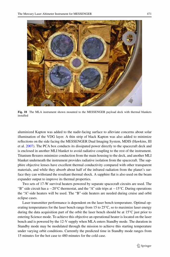
The entire instrument is covered with a ten-layer multilayer insulation (MLI) blanketas shown in Fig. 18. The outer layer of the blanket is vapor-deposited gold (VDG), andthe inner layers are vapor-deposited aluminum (VDA). During spacecraft I&T a layer of
Fig. 17 Predicted temperatures of MLA subsystems during the hottest expected orbit. The plot time starts ap-proximately 30 minutes before firing the laser. The laser beam expander output window temperature (orangeline) swings from −5°C to +65°C in less than 30 minutes
The Mercury Laser Altimeter Instrument for MESSENGER 471
Fig. 18 The MLA instrument shown mounted to the MESSENGER payload deck with thermal blanketsinstalled
aluminized Kapton was added to the nadir-facing surface to alleviate concerns about solarillumination of the VDG layer. A thin strip of black Kapton was also added to minimizereflections on the side facing the MESSENGER Dual Imaging System, MDIS (Hawkins, IIIet al. 2007). The PCA box conducts its dissipated power directly to the spacecraft deck andis enclosed in another MLI blanket to avoid radiative coupling to the rest of the instrument.Titanium flexures minimize conduction from the main housing to the deck, and another MLIblanket underneath the instrument provides radiative isolation from the spacecraft. The sap-phire objective lenses have excellent thermal conductivity compared with other transparentmaterials, and while they absorb about half of the infrared radiation from the planet’s sur-face they can withstand the resultant thermal shock. A sapphire flat is also used on the beamexpander output to improve its thermal properties.
Two sets of 17-W survival heaters powered by separate spacecraft circuits are used. The“B” side circuit has a −20°C thermostat, and the “A” side trips at −15°C. During operationsthe “A”-side heaters will be used. The “B”-side heaters are needed during cruise and orbiteclipse cases.
Laser transmitter performance is dependent on the laser bench temperature. Optimal op-erating temperatures for the laser bench range from 15 to 25°C, so to maximize laser energyduring the data acquisition part of the orbit the laser bench should be at 15°C just prior toentering Science mode. To achieve this objective an operational heater is located on the laserbench and is powered by the 12-V supply when MLA enters Standby mode. The duration inStandby mode may be modulated through the mission to achieve this starting temperatureunder varying orbit conditions. Currently the predicted time in Standby mode ranges from15 minutes for the hot case to 480 minutes for the cold case.

472 J.F. Cavanaugh et al.
4 MLA System Integration and Test
4.1 Instrument Assembly
The MLA assembly sequence was driven primarily by the cleanliness requirements for thelaser. Prior to any assembly activity the main housing was precision cleaned, and the cavitythat enclosed the laser was sealed during integration of the electronics with the housing.Laser bench integration was performed in a Class-100 clean room. Once the laser was sealedin the housing, a ground-support equipment (GSE) air filter was attached in series with thebuilt-in flight filter to provide additional protection during I&T.
The receiver telescope tubes and aft-optics were assembled on a Class-100 laminar flowbench in a Class-1000 clean room. The MLA housing with the laser and electronics wasdelivered to this area, and the telescope tubes were attached. The assembled instrument wasthen attached to its handling fixture. Before the fiber optics were connected, a series of free-space tests with the laser were performed to establish baseline performance and to calibratethe GSE power measurements that would be used throughout ground testing to monitor laserperformance.
MLA was then mounted to an optical bench that contained the alignment optics for bore-sighting. The optical axis of the alignment fixture was coaligned with the MLA laser’s op-tical axis. Each receiver’s fiber optic was then aligned to the fixture’s axis. As a final post-assembly check each fiber was back-illuminated while the laser was firing, producing animage at the alignment fixture’s focal plane showing the laser image with the receiver’s illu-minated FOV. Since the alignment was done in the lab at one atmosphere, shims on the fiberoptic connectors positioned each fiber at the vacuum focus of each telescope, causing theimage to blur but allowing for accurate evaluation of the centered images. Subsequent eval-uation of the alignment in vacuum was performed during environmental testing. The fiberswere then attached to the aft optics, completing the assembly sequence prior to instrument-level testing.
4.2 Contamination
After assembly of MLA the particulate contamination requirements were relaxed to Class-10 000 level since the most sensitive optics were sealed. All optical surfaces, particularlythe beam expander output window, were visually inspected prior to firing the laser. MLAGSE that came in close contact with the instrument was cleaned and inspected prior to eachuse. GSE covers were made for each telescope objective and the beam expander window.These were attached when the instrument was not under test. After MLA was installed onthe spacecraft with the thermal blankets, a sheet of lumalloy was taped over the receiver ob-jectives when not testing. Final inspection and cleaning of all optical surfaces was performedprior to encapsulation using bright white and ultraviolet light sources.
The GSE air filter remained attached to the laser housing until final closeout at thespacecraft level save for mass properties testing during which a small plug was installed.A gaseous nitrogen purge was applied to the spacecraft payload area during integration upto launch. This purge line was filtered, and a manifold distributed the purge gas to each in-strument. The purge line for MLA was attached near the laser filter snout at final closeoutafter the GSE air filter was removed.
The Mercury Laser Altimeter Instrument for MESSENGER 473
Table 7 MLA optical alignment allocations and margins. These parameters could be verified to within 10μrad during testing with the MLA alignment GSE
Specification
Integration margins
Laser beam axis parallel to receiver telescope axis <2 mrad
Laser beam axis perpendicular to mounting plane <5 mrad
Alignment margins
Receiver telescopes to laser beam axis (boresight) ±50 μrad
Laser beam axis to MLA reference cube (knowledge) ±50 μrad
Stability
Laser beam axis to MLA mounting plane ±50 μrad
Receiver telescopes to laser beam axis (boresight) ±100 μrad
4.3 Performance Testing
Table 3 and Table 7 show the MLA ranging and optical alignment error budgets associatedwith the performance requirements listed in Table 1. A suite of tests was designed to verifyMLA performance at the instrument level and during spacecraft testing. Subsets of this suitewere used for Aliveness and Functional testing, and the entire suite comprised the Com-prehensive Performance Test. Ancillary tests such as boresight alignment verification andtiming tests were used at key points during integration and test as calibration points and todemonstrate compliance with the MESSENGER Component Environmental Specification.
4.3.1 Bench Checkout Equipment
The set of test equipment used to verify performance was in itself a system of electronic,electro-optic, and optomechanical subsystems referred to as the Bench Checkout Equip-ment (BCE). The BCE hardware is composed of three subsystems. One equipment rackcontains the main data acquisition system, spacecraft interface simulator, timing references,and electro-optic sources. A second rack contains the alignment data acquisition and controlsystem. An optomechanical target assembly is used for functional and alignment testing.Several hundred meters of fiber optic cable were also used to couple signals and provideconstant time-delay paths.
During instrument-level testing the BCE used the MESSENGER-supplied spacecraft in-terface simulator to provide power and transfer commands and data to and from MLA.After integration with the spacecraft the BCE acquired real-time telemetry via the MES-SENGER ground data system network. During all phases of testing the BCE captured andtime-stamped each and every laser pulse emitted by MLA and provided simulated returnsignals and noise at the MLA receiver telescope. Laser pulse energy was continuously mon-itored.
Simulated return signals were generated by a diode-pumped Nd:YAG laser housed withinthe rack that produced 5-μJ 1-ns pulses when triggered by the timing electronics. Thesepulses were fed through an optical attenuator and fiber coupled to a holographic diffuser,which distributed the signal power in a 0.006-steradian cone to be collected by one of theMLA receiver telescope apertures. Optical background noise was simultaneously coupledin a similar manner using a continuous-wave (CW) Nd:YAG laser source.

474 J.F. Cavanaugh et al.
The BCE used a Stanford Research Systems SR620 time-interval analyzer and two In-GaAs photodiodes to independently measure the delay between each emitted MLA laserpulse and the corresponding simulated return pulse. The timebase for the SR620 is arubidium-based oscillator. The drift of this oscillator is measured by recording the phasebetween its 1-Hz output to a 1-Hz tick generated by a Global Positioning System (GPS)receiver.
4.3.2 Laser Performance Testing
Two different laser beam termination schemes were used for monitoring the MLA laser.Both were designed to provide a “light-tight” seal to the MLA beam expander to preventdamaging levels of power from leaking into the receivers and afford an additional level ofpersonnel safety. In addition both schemes were required to minimize back reflections intothe laser itself.
One assembly is illustrated in Fig. 19. This scheme, known as the beam dump, was anintegral part of the alignment test fixture and used a beam splitter to direct 90% of thelaser pulse power into a holographic diffuser and then focused a portion thereof into a 0.22numerical-aperture optical fiber for transmission to a Molectron JD2000 Joulemeter energymonitor and an InGaAs photodiode used for timing and temporal pulse width measurement.The remainder of the energy was transmitted to a charge-coupled device (CCD) camera usedfor beam diagnostics and redirected via retroreflector into one of the four MLA telescopes.Filter holders allowed for placement of volume-absorbing neutral-density filters to attenuateoptical power to usable levels.
The second assembly, referred to as the beam stop, was used primarily for spacecraft-level testing and incorporated a Macor ceramic insert to diffusely reflect the incident laserpower. The Macor transmits approximately 1% of the laser pulse, allowing for placement ofan optical fiber on the back of the beam stop used with the BCE in the same manner as thebeam dump fiber.
4.3.3 Boresight Alignment Verification
Two different methods were used to verify the MLA boresight alignment, or angular offsetbetween the transmitted laser beam and each receiver telescope’s field of view.
The initial boresight alignment was performed on a laboratory optical bench usinga 2.5-m-focal-length collimator with a 400-mm-diameter off-axis parabola. The initial align-ment described in Sect. 4.2 used this fixture. To verify the alignment with this fixture theMLA laser beam axis was aligned to the optical axis of the fixture. With the MLA laserturned off, a 1,064-nm continuous-wave point source at the focus of the fixture was mechan-ically swept across the MLA field of view while monitoring noise counts in MLA telemetry.MLA noise counts were then plotted against the point source offset to assess the receiveralignment. This method also enabled simultaneous alignment testing of all four receivertelescopes.
During MLA instrument environmental testing and spacecraft-level testing the laserbeam alignment to the receiver telescopes was measured by redirecting a portion of thetransmitted laser pulse back into one of the four receiver tubes using a lateral transfer hol-low retroreflector (LTHR). At the output of the LTHR a pair of motorized Risley prismsdeflected the beam at a programmable angular offset into the telescope. By sweeping theangular offset in orthogonal directions across each telescope’s field of view and monitoringthe power received at the MLA detector, a centroid was computed that indicated the relative

The Mercury Laser Altimeter Instrument for MESSENGER 475
Fig. 19 MLA laser beam dump and alignment fixture shown in the configuration used to verify alignmentafter MLA was installed on the MESSENGER spacecraft S/C
angular offset of the laser beam to each telescope. Relative pulse power received was mea-sured by computing the change in detected pulse width and normalizing for each tube. Thesetup used during spacecraft-level testing is depicted in Fig. 19.
4.4 Calibration and Characterization
4.4.1 Instrument Calibration
MLA provides three measurements: the laser-pulse time-of-flight, the echo-pulse width, andthe echo-pulse energy, along with a precise epoch time. To calibrate these measurements

476 J.F. Cavanaugh et al.
the MLA BCE continuously monitored laser pulse energy and range timing over the entiredynamic range of the instrument at all detector gain settings and comparator thresholds.
Three methods were used to calibrate the range measurement. First, MLA and a cali-brated time interval analyzer simultaneously measured a sequence of simulated range signalsgenerated by the BCE. These simulated optical signals varied in time delay from approxi-mately 1 ms to 13 ms after the transmitted MLA laser pulse, corresponding to the expectedtime delays to be seen in Mercury orbit from 200 km to 1,900 km.
Second, a series of closed-loop delay tests was performed by transmitting the MLA laserpulse via the beam dump described in Sect. 4.3.2 through five different lengths of fiber opticcable coupled back to the receiver using the holographic diffuser described in Sect. 4.3.1.The fiber lengths ranged from approximately 140 m to 270 m. Finally, the instrument rangebias was evaluated using the boresight alignment fixture LTHR described in Sect. 4.3.3. Thissetup reflected the attenuated MLA laser pulse directly into the receiver telescope over anoptical path length of 1 m.
To locate the measurement point on Mercury’s surface a precise knowledge of the MLAboresight axis relative to the spacecraft frame is also needed. Pointing verification testswere performed during instrument thermal-vacuum (TVAC) testing, and on the spacecraftafter integration, during TVAC, and prior to launch at the Astrotech integration facility inTitusville, FL.
Timing tests with the MESSENGER spacecraft were also performed after integrationto verify that each laser shot was correctly time-stamped. All timing measurements werereferenced to GPS-based Universal Time Coordinated (UTC) epoch time.
4.4.2 Environmental Testing
All engineering models of electronic, optical, and laser subassemblies were thermally cycledat ambient pressure. Optics were tested under vacuum to verify focus shift. The flight lasersubassembly underwent full thermal vacuum testing while monitoring beam quality, pulseshape, and energy (Krebs et al. 2005).
A planet simulator target was also used during instrument-level thermal balance testingto provide a radiative input to MLA and measure the instrument’s response to thermal tran-sients. These tests provided valuable insight to the thermal performance during orbit condi-tions. The MLA thermal vacuum test setup is shown in Fig. 20. Cold plates were attachedto the laser bench and main housing to achieve qualification temperatures.
During instrument TVAC testing the laser pointing was continuously monitored using atelescope and charge-coupled device (CCD) camera outside the chamber that imaged the
Fig. 20 MLA thermal vacuum test fixture used for instrument-level thermal vacuum testing. The fixtureprovided a stable platform to monitor alignment and inject optical signals during testing

The Mercury Laser Altimeter Instrument for MESSENGER 477
MLA laser spot along with a reference cube on the instrument. Boresight verification wasperformed using the LTHR and Risley setup at each TVAC test plateau as well. After instru-ment TVAC testing the boresight was again verified using the optical bench setup.
During spacecraft environmental testing cold plates were again attached to the MLAlaser bench and main housing to provide additional temperature cycles. MLA testing onthe spacecraft was limited to range timing with simulated signals. Pointing verification wasdone before and after spacecraft TVAC.
4.5 Postlaunch Checkout Results
MLA was first powered on August 19, 2004, 16 days after launch (L+16). It remained inStandby mode for approximately 24 hours to allow time for the laser bench to warm up. Thiswarm up also allowed any contaminants (our primary concern was water condensate left asice on the optics) to sublime. A detector noise characterization test was performed shortlyafter turn on. Noise levels were observed to be nearly identical to the values seen duringground testing. Another noise characterization was run on L+17 with a similar result.
On August 20, 2004 (Launch + 17 days), MLA was commanded to Science mode, caus-ing the laser to fire. Laser performance was normal with the laser energy monitor report-ing 19 to 20 mJ of energy. Figure 21 shows a plot of postlaunch laser energy with an equiva-lent cold turn-on during vacuum testing. The slightly lower energy (∼0.4 mJ, or 2%) can beattributed to the lack of beam termination at the end of the beam expander. During testingit was observed that the laser energy monitor was sensitive to back reflection from eitherthe beam stop or the beam dump. Since it was impossible to fire the laser unterminated onthe ground this condition could not be verified, but the drop in the monitor reading was ex-pected. The matching upward slope after several minutes of operation and the laser diodecurrent pulse width indicate a healthy laser.
The need for additional power from the operational laser bench heater during this firstcruise operation of the laser was unanticipated. As this heater was switching on for four
Fig. 21 MLA laser energy comparison showing pulse energy over a seven-minute window measured beforelaunch and 17 days after launch

478 J.F. Cavanaugh et al.
minutes during a nine-minute period it added approximately 250 mA to the total MLA cur-rent. Since the spacecraft C&DH computes power by multiplying the current monitor valuetimes the bus voltage, and the MLA current is only sampled at the 35 ms peak (see Fig. 14),the computed power with the heater was 40.8 W. This apparent power draw violated a MES-SENGER spacecraft autonomy rule that automatically shuts down any instrument drawingexcessive current. This condition was realized just prior to the planned laser turn-on and thetest proceeded with the agreement of the payload systems and spacecraft systems engineers.The autonomy rule executed as expected and turned off the instrument after approximatelyeight minutes. This rule was subsequently updated to account for this condition.
4.6 Cruise Calibration
In May 2005 MESSENGER successfully performed a sequence of Earth scan maneuversto calibrate MLA pointing, radiometry, and laser pulse timing during cruise (Smith et al.2006). Additional radiometric calibrations were performed during the two Venus flybys.
4.7 Data Products
The time-of-flight range data from MLA will be combined with MESSENGER spacecraftpointing knowledge and Radio Science range and range-rate tracking data obtained from theDeep Space Network to produce Digital Elevation Models (DEMs) of the planet’s surfacereferenced to Mercury’s center of mass.
MESSENGER’s inertial measurement unit and star tracker provide the required pointingdata. The radio frequency data link signals are used to determine the precise trajectory ofthe spacecraft with respect to the planet’s center of mass. Once the spacecraft orbit andattitude determinations are initially made, the MLA time-of-flight measurements are usedto determine the surface altitude. These surface measurements sample the planet’s shapeand are fed back into the precision orbit and pointing determination to improve these datasets. Crossover analysis identifies and correlates multiple range measurements of proximatesurface features made during different orbits. Reiteration of this process produces the finaldata product in the form of a DEM. This DEM will be used to determine and track theplanet’s shape to refine the measurement of the amplitude of the forced physical libration.
Simultaneous pulse width data from the high- and low-threshold channels will be used todetermine received pulse energy, which along with the transmitted energy measurement willindicate surface reflectivity at 1,064 nm. Pulse width measurements are also used to assesslaser spot-scale, surface slope, and roughness.
4.8 Operation Plans and Observing Strategy
MLA will operate in Science mode, sampling the planet’s surface, when the line-of-sightrange to Mercury is less than 1,200 km under spacecraft nadir pointing or the slant range isless than 800 km. These limits result in an operating time of approximately 20 to 40 minutesduring each 12-hour orbit. Over the life of the mission or approximately 700 orbits, MLAwill make over 8 million range measurements at its laser pulse repetition rate of 8 Hz.
For the remainder of each orbit MLA will be commanded to Keep Alive mode to conservepower. In this mode the laser and range measurement electronics are powered off and theinstrument dissipates the heat generated by the laser and absorbed from the planet duringthe brief measurement period. Depending on the orbit, MLA will then be commanded toStandby mode 15 to 480 minutes prior to the next Science mode pass. In Standby mode the

The Mercury Laser Altimeter Instrument for MESSENGER 479
laser and range measurement electronics are again powered without actually firing the laserto increase overall instrument power and ensure that the laser amplifier is at its minimumoperating temperature of 15°C prior to entering Science mode. During eclipse periods whenMercury blocks the Sun from the MESSENGER solar panels the instrument is powered off.
5 Summary
The successful development, integration, testing, and deployment of MLA have demon-strated the practicability of its scalable, miniaturized laser transmitter, low-cost scalable re-ceiver architecture, and low-power time-of-flight measurement electronics for future spaceflight missions. Scaling of laser transmitter power is achievable by either removing the laseramplifier (using just the oscillator section) to generate a laser pulse approximately one orderof magnitude less powerful or by adding an amplifier to achieve higher laser pulse power.Scaling of the receiver aperture area may be accomplished by adding or removing individualtelescopes. A scaled version of the MLA architecture has been used in the design of the Lu-nar Reconnaissance Orbiter (LRO) Lunar Orbiter Laser Altimeter (LOLA) instrument (Chinet al. 2007). LOLA will use the MLA laser oscillator design to generate 2.7-mJ laser pulsesand a single receiver telescope to profile the lunar surface from a nominal altitude of 50 kmabove the Moon. LRO is scheduled to launch in October 2008.
MLA will provide the first precise laser pulse time-of-flight measurements of the surfaceof Mercury. This unique data set along with MESSENGER spacecraft pointing and DeepSpace Network tracking data will be used to accurately determine the detailed topography ofMercury’s northern hemisphere, measure topographic profiles across major geologic struc-tures, track large-scale planetary shape to measure the planet’s libration, and measure thesurface reflectivity of Mercury at 1,064 nm.
Acknowledgements We wish to thank the following individuals for their significant contributions to thesuccessful completion of the MLA instrument effort: Edward Amatucci, Adrienne Beamer, Pete Dogoda, TomFeild, Ron Follas, Ame Fox, Jeff Guzek, Randy Hedgeland, Sid Johnson, Igor Kleyner, Steve Li, Steve Lin-dauer, Billy Mamakos, Dave McComas, Roger Miller, Tony Miller, Lou Nagao, Karen Pham, Steve Schmidt,Stan Scott, Nancy Stafford, Jon Vermillion, Ken Waggoner, Tony Yu, Ron Zellar, and the MESSENGERteam at APL, in particular Steve Jaskulek, Eliot Rodberg, Chuck Schlemm, Stan Kozuch, Jack Ercol, and TedHartka.
References
J.B. Abshire, X. Sun, R.S. Afzal, Appl. Optics 39, 2449–2460 (2000)G. Chin et al., Space Sci. Rev. (2007). doi:10.1007/s11214-007-9153-yJ.J. Degnan, J. Geodyn. 34, 503–549 (2002)J. Garvin et al., Phys. Chem. Earth 23, 1053–1068 (1998)S.E. Hawkins, III et al., Space Sci. Rev. (2007, this issue). doi:10.1007/s11214-007-9266-3D.J. Krebs, A.M. Novo-Gradac, S.X. Li, S.J. Lindauer, R.S. Afzal, A.W. Yu, Appl. Optics 44, 1715–1718
(2005)N. Paschalidis et al., IEEE Trans. Nucl. Sci. 49, 1156–1163 (2002)L. Ramos-Izquierdo et al., Appl. Optics 44, 1748–1760 (2005)D.E. Smith et al., Science 279, 1686–1692 (1998)D.E. Smith et al., Science 311, 53 (2006)S.C. Solomon et al., Planet. Space Sci. 49, 1445–1465 (2001)X. Sun, J.F. Cavanaugh, J.C. Smith, A.E. Bartels, Proceedings of the 22nd International Laser Radar Confer-
ence (ILRC 2004). Special Publication SP-561, European Space Agency, Noordwijk, The Netherlands,2004, pp. 961–964
M.T. Zuber et al., J. Geophys. Res. 97, 7781–7797 (1992)H.J. Zwally et al., J. Geodyn. 34, 405–446 (2002)